


 Loading...
96M13156
High-accuracy Digital Contact Sensor
GT2-PA12K/PA12
Instruction Manual
Introduction
Read this instruction manual carefully prior to operating this product. For connection, settings and precautions on use, make sure to read the GT2 Series instruction manual included with the amplifier. Be sure to store this manual in a convenient place so that it is readily accessible for reference. Ensure that the personnel who will actually operate the product have access to this manual. For details of each function, refer to the GT2 Series User’s Manual.
You can download the User’s Manual from KEYENCE homepage (http://www.keyence.com/).
|
|
|
It indicates a hazardous situation which, if not |
|
WARNING |
||
|
|
avoided, could result in death or serious injury. |
|
|
|
|
|
|
|
|
|
|
NOTICE |
|
It indicates a situation which, if not avoided, could |
|
|
result in product damage as well as property damage. |
|
|
|
|
|
Safety precautions
|
|
|
• This product is designed to detect the target object. |
|
|
|
Do not use this product to protect human bodies or |
|
|
|
a part of a human body. |
|
WARNING |
||
|
|
• This product is not intended for use as an explosionproof |
|
|
|
|
product. Do not use this product in hazardous locations |
|
|
|
and/or potentially explosive atmospheres. |
|
|
|
|
|
|
|
|
|
|
|
Warming up |
|
|
|
The circuit is not stable immediately after the power |
|
|
|
turns ON, which sometimes causes the indicated |
|
|
|
value to gradually fluctuate. Wait for about 5 minutes |
|
|
|
after the power turns on before using. |
|
|
|
Handling of the sensor head |
|
|
|
• This device is a precision machine. Do not drop, or |
|
|
|
cause any other impact to this device. Doing so may |
|
|
|
cause damage or malfunction. |
|
|
|
• Do not apply weight greater than what is listed |
|
|
|
below to the spindle. Do not apply rotational torque. |
|
|
|
Otherwise the spindle may break. |
|
|
|
• The spindle can rotate a maximum of 4.5°. When |
|
|
|
using an offset contact (OP-77683) or similar, if |
|
|
|
pressure in the rotational direction is applied to the |
|
NOTICE |
|
contact, the measurement position may change. |
|
|
|
• When attaching and removing contacts, make sure |
|
|
|
that the sensor head is detached from any metallic |
|
|
|
plates, etc. Apply a tightening torque of 0.2 N•m or |
|
|
|
less when attaching the contact. |
|
|
|
• If dust, metal powder, or similar becomes attached |
|
|
|
to the sliding part of the sensor head, mechanical |
|
|
|
responses may become slow. If this happens, |
|
|
|
replace the end of the sensor head with a |
|
|
|
replacement dust seal (OP-87932). Refer to the |
|
|
|
instruction manual included with the replacement |
|
|
|
dust seal (OP-87932) for instructions on how to |
|
|
|
replace the dust seal. |
|
|
|
• Although the GT2-PA12K/PA12 has a protection |
|
|
|
rating of IP67, avoid using it immersed in water or in |
|
|
|
places where liquid such as oil may come into |
|
|
|
contact with it. |
|
|
|
|
Checking the package
GT2-PA12K/PA12
Sensor head × 1 Precautions on Handling × 2
If you find that a part is faulty or broken, contact your KEYENCE representative.
Sensor head connection cable
GT2-CH2M/5M/10M/20M |
GT2-CHL2M/5M/10M/20M |
GT2-CHP2M/5M/10M |
(M8 straight connector) |
(M8 L-shaped connector) |
(M8 oil-resistant straight connector) |
Names of parts of the sensor head
● GT2-PA12K/PA12
Air supply hole


 Cable connector
Cable between the sensor head and relay connector
Operation indicator
Mounting fixture
Spindle
Dust seal |
Contact |
Mounting the sensor head
When mounting to the jig, make a round hole on the jig beforehand.
Using mounting bracket A/C
1 Work the sensor head mounting part as below.
|
|
|
|
|
|
|
|
|
|
|
|
0.5 1.0*2 |
|
|
|||||||
|
|
|
|
|
|
±1° |
|
|
|
|
|
|
|
|
|
|
|
||||
|
|
|
|
|
|
45° |
|
|
|
|
|
|
|
|
|
|
|
|
|
||
|
|
|
|
|
|
Tightening |
|
|
|
|
|
|
A |
Nut mounting side |
|||||||
|
|
|
|
|
|
sleeve |
|
|
|
|
|
|
|
|
|
|
|
|
|
||
|
|
|
|
|
|
|
|
|
|
|
|
|
|
|
|
|
|
|
|||
|
|
1 |
|
|
|
insertion |
|
|
|
|
|
|
|
|
|
|
|
|
|
||
|
|
|
|
|
|
|
|
|
|
|
|
|
|
|
|
|
|
||||
|
|
* |
|
|
|
side |
|
|
|
|
|
|
|
|
|
|
|
|
|
||
|
+0.027) |
|
|
|
|
|
|
|
|
|
|
|
|
|
|
|
|
||||
|
|
.005 |
|
|
|
|
|
|
|
|
|
|
|
|
|
|
|
|
|
|
|
|
G8( |
+0 |
|
|
|
|
|
|
|
|
|
|
5.5 11.3* |
2 |
|
||||||
10 |
|
|
|
|
|
|
|
|
|
|
|
|
|||||||||
φ |
|
|
|
|
|
φ0.025 |
A |
|
|
|
|
|
|
||||||||
|
|
|
|
|
|
|
|
|
|
|
|
|
|
|
|
|
|
(Unit: mm) |
|||
*1 For head mounting bracket C |
*2 Processing accuracy: ±0.05 |
||||||||||||||||||||
|
φ10 |
+0.1 |
|
|
|
|
|
|
|
|
|
|
|
|
|
|
|
|
|
|
|
|
|
+0.005 |
|
|
|
|
|
|
|
|
|
|
|
|
|
|
|
|
|
|
|
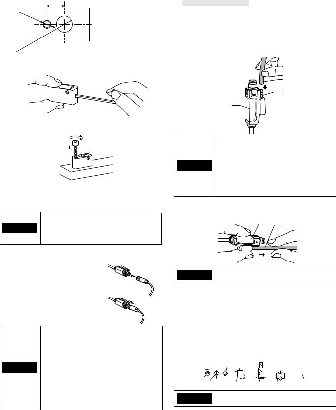
2 Insert the tightening sleeve into the hole made in step 1 (from the chamfered side), and loosely tighten with the nut.
Next, insert the sensor head.
Tightening sleeve
Chamfered side
Nut
If the nut is fully tightened when the sensor head
NOTICE is not yet inserted, the fixture will become deformed.
3 Secure the sensor head with the supplied key wrench and tighten the nut with a wrench or similar tool.
Wrench or similar tool
Key wrench
Dust seal
NOTICE |
Apply a tightening torque of 5 to 7 N•m (the |
recommended tightening torque is 5 N•m). |
1
Using mounting bracket F
1 Refer to the illustration below, and cut the jig to create a sensor head mounting hole.
|
|
|
|
|
|
8.5 |
|
M |
|
|
|
|
|
|
|
4 |
x |
0. |
|
|
|
|
|
|
|
7 |
|
|
|
|
|
0 |
|
Make sure that the metal plating |
|
|
|
|
|
|
|
+ |
|
0 |
|
mounting bracket F attaches to is at |
||
.2 |
0 |
|
||||
|
0 |
|
5 |
|
||
|
|
|
.0 |
|
|
|
|
|
0 |
|
|
|
|
|
+ |
|
|
|
|
|
8 |
|
|
|
|
least 5 mm thick. |
|
|
|
|
|
|
|
|
2 Loosen the screw on the side of mounting bracket F using the supplied hexagonal wrench.
3 Align mounting bracket F with the hole made in step 1 and secure it using the supplied hexagonal wrench.
4 Insert the sensor head, and tighten the screw loosened in step 2 using the supplied hexagonal wrench to secure. The recommended tightening torque is 0.6 to 0.8 N•m. Make sure that the dust boot does not obstruct the metal plating that mounting bracket F is attached to.
•When loosening the screw with the hexagonal wrench, insert the long end of the hexagonal
NOTICE |
wrench into the hex screw and rotate the small end |
|
with your hand. |
•Do not forcibly tighten the hex screw.
Connecting the sensor head connection cable
1 Insert the sensor head connection cable into the cable connector on the relay connector cable.
2 Secure the connector with the sensor head connecting cable screw.
•When connecting the connector, be sure to insert it straight, and tighten it securely. (Recommended tightening torque: 0.4 to 0.5 N•m*)
If the connection is not tight enough, the connector may be loosened by vibration or other causes,
leading to a connection failure.
(* After tightening it strongly by hand, use pliers or NOTICE other tools to rotate it about 30° for further
tightening.)
•When the head is attached to a moving part, and the cable will be repeatedly bent, ensure that the cable between the sensor head and relay connector does not bend. Instead, bend the sensor head cable connecting the relay connector and the amplifier.
Installing the air tube (GT2-PA12K/PA12)
Compatible air tubes
Use a tube with the following specifications.
|
Item |
Description |
|
Recommended tubing material |
Urethane |
||
|
|
Outer |
4 mm |
|
|
diameter |
|
Tubing size |
|
|
|
|
Inner |
2.5 mm |
|
|
|
||
|
|
diameter |
|
|
|
|
|
|
|
|
|
How to attach/detach the air tube
•Attaching the air tube
Insert the air tube into the air supply hole on the relay amplifier.
Air tube
Air supply hole
Relay connector
• For best results, cut the end of the tube at a right angle, ensure that the outer perimeter is not damaged, and that it still maintains a circular cross section.
• If the tube is not properly inserted, air leakage may NOTICE result.
•After attaching, pull on the tube to make sure it is secure.
•Use a urethane tube. Make sure it also has a bending radius of at least 50 mm.
•Detaching the air tube
To detach the air tube, pull the air tube in the direction of the arrow, as indicated in the figure below.
Relay connector
Air tube
Before detaching the tube, be sure to stop any air
NOTICE flow.
Supplying air
•Refer to the diagram below to create a pneumatic circuit.
•Use an air filter, mist separator, etc. to provide clean dry air. Empty the drainage from the filter regularly, before it exceeds the specified line.
•Make sure that the air pressure of the supplied air is constant and in the range of 0.24 to 0.26 MPa. Use a precision regulator to control the air pressure. If the air pressure is below 0.24 MPa, the spindle may not extend fully.
•When supplying air (with the spindle extended), up to 3L/min of air will be emitted from the tip of the dust seal.
•The measuring ability of the device changes according to the air pressure of the air supply. Refer to "Specifications" for details.
|
Mist separator |
|
|
|
|
AIR |
|
|
|
|
|
Pressure |
|
|
|
|
|
source |
|
|
|
Air supply part |
|
Air filter |
Precision regulator |
Solenoid valve |
Speed controller |
||
GT2-PA12K/PA12 |
|||||
|
|
|
|
||
NOTICE |
If the air supply pressure exceeds 0.5 MPa, the sensor |
||||
head may become damaged. |
|
||||
2
Loading...