


 Loading...
96M12754
High-accuracy Digital Contact Sensor
GT2-100 Series Instruction Manual
■ Symbols
The following symbols alert you to matters concerning the prevention of human injury and product damage. Be sure to read these messages carefully.
|
|
|
It indicates a hazardous situation which, if not avoided, |
|
|
|
WARNING |
|
|||
|
|
could result in death or serious injury. |
|
||
|
|
|
|||
|
|
|
|
|
|
|
NOTICE |
|
It indicates a situation which, if not avoided, could result |
|
|
|
|
in product damage as well as property damage. |
|
||
|
|
|
|
||
|
|
|
|
|
|
|
Safety Information for GT2-100 Series |
|
|||
|
|
|
|
|
|
|
|
|
If the following conditions are encountered, immediately turn |
|
|
|
|
|
OFF the power. Continuing to use the GT2-100 Series under |
|
|
|
|
|
these abnormal conditions may cause equipment failure. |
|
|
|
|
|
• When water or foreign matter enters the controller |
|
|
|
WARNING |
|
|||
|
|
• When the GT2-100 Series is dropped or the housing is |
|
||
|
|
|
|||
|
|
|
damaged |
|
|
|
|
|
• When the GT2-100 Series produces smoke or an |
|
|
|
|
|
abnormal smell |
|
|
|
|
|
|
|
|
|
|
|
• Do not use the GT2-100 Series with a voltage other |
|
|
|
|
|
than specified voltage, as this may cause fire, electric |
|
|
|
|
|
shock or equipment failure. |
|
|
|
|
|
• Do not disassemble or modify the GT2-100 Series. |
|
|
|
|
|
This may cause fire or electric shock. |
|
|
|
WARNING |
|
|||
|
|
• Do not use this product for the purpose to protect a |
|
||
|
|
|
human body or a part of human body. |
|
|
|
|
|
• This product is not intended for use as explosion-proof |
|
|
|
|
|
product. Do not use this product in a hazardous |
|
|
|
|
|
location and/or potentially explosive atmosphere. |
|
|
|
|
|
|
|
|
|
|
|
• Be sure to turn OFF the power of the GT2-100 Series and |
|
|
|
|
|
any connected devices before connecting or disconnecting |
|
|
|
|
|
the cables. Otherwise, there may be a risk of damage. |
|
|
|
|
|
• Do not turn OFF the power while setting parameters. |
|
|
|
|
|
Otherwise, the settings may be partially or completely lost. |
|
|
|
|
|
• At startup and during operation, be sure to monitor the |
|
|
|
|
|
function performance of the GT2-100 Series. |
|
|
|
|
|
• Do not modify the GT2-100 Series or use it in any way |
|
|
|
|
|
other than described in the specifications. |
|
|
|
|
|
• The function performance of products used or modified |
|
|
|
|
|
in this way cannot be guaranteed. |
|
|
|
|
|
• When the GT2-100 Series is used in combination with |
|
|
|
|
|
other instruments, function performance may be degraded, |
|
|
|
|
|
depending on operating conditions and the surrounding |
|
|
|
|
|
environment. Use the GT2-100 Series after fully studying |
|
|
|
|
|
the effect of combined use with other instruments. |
|
|
|
|
|
• Do not expose the GT2-100 Series and peripheral |
|
|
|
|
|
devices to sudden temperature change. This may |
|
|
|
|
|
cause condensation, damaging the equipment. |
|
|
|
NOTICE |
|
● Environmental conditions |
|
|
|
|
To use the GT2-100 Series properly and safely, do not |
|
||
|
|
|
install the GT2-100 Series in the following locations. |
|
|
|
|
|
Use of this equipment in an improper environment |
|
|
|
|
|
may cause equipment failure. |
|
|
|
|
|
• |
Locations outside |
|
|
|
|
• |
Locations with high humidity, a large amount of dust, |
|
|
|
|
|
or poor ventilation |
|
|
|
|
• Locations where the temperature rises excessively |
|
|
|
|
|
|
due to direct sunlight, etc. |
|
|
|
|
• Locations near corrosive or flammable gas |
|
|
|
|
|
• Locations where the GT2-100 Series is directly |
|
|
|
|
|
|
subjected to vibration or impact |
|
|
|
|
• |
Locations where water, oil or chemicals may come into |
|
|
|
|
|
contact with the GT2-100 Series |
|
|
|
|
• |
Locations where static electricity may easily occur |
|
|
|
|
● Noise countermeasures |
|
|
|
|
|
Installation near sources of electrical noise such as a |
|
|
|
|
|
power source or a power cable may cause malfunction |
|
|
|
|
|
or failure of the equipment. Adopt appropriate |
|
|
|
|
|
countermeasures against noise by using a noise filter |
|
|
|
|
|
or wiring cables in separate ducts, attaching insulation |
|
|
|
|
|
to the amplifier or the sensor head, etc. |
|
|
●Handling of the sensor head
•The GT2-100 Series and peripheral devices are precision machines. Do not drop, or cause any other impact to these devices. Doing so may cause damage or malfunction.
•Do not apply force greater than what is listed below to the spindle. Do not apply torque in the rotation direction. Otherwise the spindle may break.
•The GT2-P12KL(F)/P12L(F)/PA12K/PA12 spindle can rotate a maximum of about 4.5°. When using an offset contact (OP77683) or similar, if pressure in the rotational direction is applied to the contact, the measurement position may change.
•Although the GT2-PA12K/PA12/H12K/H12KF/H12/H12F/ H32/H50/A12K/A12/A32/A50 has a protection rating of
NOTICE |
IP67, avoid using it immersed in water or in places where |
|||||||||
|
liquid such as oil may come into contact with it. |
|||||||||
• |
Although the GT2-P12K(F)/P12(F) has a protection rating of |
|||||||||
|
IP67G/NEMA Type 13, some types of oil may damage the device. |
|||||||||
• |
If dust, metal powder, or similar becomes attached to the sliding part |
|||||||||
|
of the sensor head, mechanical responses may become slow. If this |
|||||||||
|
happens, replace the dust seal with a replacement dust seal (OP- |
|||||||||
|
87932). Refer to the instruction manual included with the replacement |
|||||||||
|
dust seal (OP-87932) for instructions on how to replace the dust seal. |
|||||||||
|
|
|
|
|
|
|
|
|
|
|
|
|
|
|
|
|
|
|
|
|
|
|
|
|
|
|
|
|
|
|
|
|
|
|
|
|
|
|
|
|
|
|
|
|
|
|
|
|
|
|
|
|
|
|
|
|
|
|
|
|
|
|
|
|
|
|
|
|
|
|
|
|
|
|
|
|
|
|
|
|
|
|
|
|
|
|
|
|
|
|
|
|
|
|
|
|
|
|
|
|
|
|
|
|
|
|
|
|
|
|
|
|
|
|
|
|
|
|
|
|
|
|
|
|
|
|
|
|
|
|
|
|
|
|
|
|
|
|
|
|
|
|
|
|
|
|
|
|
|
|
|
|
|
|
|
|
|
|
|
|
|
|
|
|
|
|
|
|
|
|
|
|
|
|
|
30 N |
100 N |
1 N |
■ Other precautions
●Effects of surrounding air temperature
To use the GT2-100 Series in high accuracy applications, do not use the GT2-100 Series in the environment in which the surrounding air temperature changes sharply. It will take about 40 minutes on the 12 mm type, and 60 minutes for the 32 mm/50 mm type for the internal temperature distribution to stabilize when the surrounding air temperature has changed by 10°C.
●Warming up
The circuit is not stable immediately after the power turns ON, which sometimes causes the indicated value to gradually fluctuate. Wait for about 5 minutes when using the 12 mm type and about 10 minutes when using the 32/50 mm type after the power turns on before starting operation.
●GT2-PA12K/PA12 (See illustration 1 for the pneumatic circuit)
•This model uses a single-acting cylinder. The internal spring will return the sensor head to its home position.
•The air supply hole cannot be removed.
•Use an air filter, mist separator, etc. to provide clean dry air. Empty the drainage from the filter regularly, before it exceeds the specified line.
•Before connecting the air tube to the air supply hole, be sure to blow plenty of air through the pipes (flushing) to remove any foreign matter.
•Make sure that the air pressure of the supplied air is constant and in the range of 0.24 to 0.26 MPa. Use a precision regulator to control the air pressure. If the air pressure is below 0.24 MPa, the spindle may not extend fully.
•When supplying air (with the spindle extended), up to 3L/min of air will be emitted from the tip of the dust seal.
•The measuring ability of the device changes according to the air pressure of the air supply. Refer to  "Specifications" (Page 14) for details.
●GT2-A12K(L)/A12(L)/A32/A50 (See illustration 1 for the pneumatic circuit)
•This model uses a single-acting cylinder. The internal spring will return the sensor head to its home position when air pressure is removed. DO NOT supply air to the exhaust valve.
•The air cylinder cannot be removed.
•Use the regulator to supply the stable air pressure to the sensor head.
•Use the air filter and mist separators to supply dry air. Empty the drainage from the filter regularly, before it exceeds the specified line.
•Make sure that the air pressure of the air supply is constant and in the range of 0.25 MPa to 0.5 MPa.
•The coupling socket and the exhaust valve that are supplied with the air cylinder are dedicated for this product. They cannot be removed.
Mist separator |
|
|
|
|
AIR |
|
|
|
|
Pressure source |
|
|
Air supply part |
|
Air filter Precision regulator |
Solenoid |
Speed |
||
|
||||
Illustration 1 - Pneumatic circuit |
valve |
controller |
|
|
|
|
|
●Power supply
•Noise superimposed on the power supply may cause malfunction. Be sure to use the DC stabilized power supply provided with an insulation transformer.
•In the case of a commercially available switching regulator, be sure to ground the frame ground terminal or the ground terminal.
●About the dust boot
When the dust boot of the sensor head is damaged, use an optional dust boot sold separately (For GT2-P12K(F)/P12(F)/H12K(F)/H12(F)/A12K/A12: OP-84332 (Material: NBR (attached when shipped)). For GT2-P12K(F)/P12(F): OP-87859 (Material: Fluororubber). For GT2-H32/A32: OP-84459 (Material: NBR (attached when shipped)). For GT2-H50/A50 (Material: NBR (attached when shipped)).). Attach the dust boot correctly.
The dust boot may deteriorate, depending on the environment it is used in. In this case, replace the dust boot regularly.
* Do not use the dust boot on the GT2-P12KL/P12L/PA12K/PA12/H12KL(F)/H12L(F)/H32L.
 Precautions on Regulations and Standards
■ CE Marking
●EMC Directive (2004/108/EC)
•Applicable standardEMI:EN61326-1, Class A EMS:EN61326-1
•This product is designed for use in industrial environments.
•The length of cable connected to the power supply terminal block must be less than or equal to 30 m.
Remarks These specifications do not give any guarantee that the end-product with this product incorporated complies with the essential requirements of EMC
Directive. The manufacturer of the end-product is solely responsible for the compliance on the end-product itself according to EMC Directive.
■ UL Certificate
UL File No. E120439 (Category: NRNT2/NRNT8)
•Use the power supply with Class 2 output defined in NFPA70 (NEC: National Electrical Code).
•GT2 series are evaluated as open type devices. These products can not be a part of an enclosure.
1 |
GT2-100-M-E |
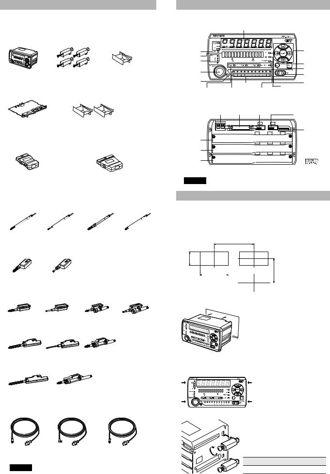
Package Contents
The product package of each model should include the following items. Check that all items are included before use.
■ Amplifier parts
● Amplifier
GT2-100N/100P
Amplifier x 1 |
|
Dummy connector x 1 |
Instruction manual x 1 |
Mounting bracket x 4 |
(Mounted on the amplifier) |
● Head expansion board
GT2-E3N/E3P
Head expansion board x 1 |
Dummy connector x 2 |
|
(Mounted on the board) |
● I/O connector |
|
OP-22185 |
OP-84456 |
(MIL socket connector 20-pin) |
(MIL socket connector 30-pin) |
Hood cover, Housing x 1 |
Hood cover, Housing x 1 |
Contact x 25 |
Contact x 35 |
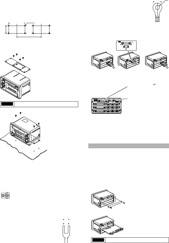
 Identifying Part Names and Functions
■ Front (display/operation section)
Digital LED display
Special output indicator 


Detection level indicator 


Special output indicator |
Arrow buttons |
Bar LEDs |
|
|
|
|
|
Bank indicator |
|
|
|
|
[MODE] button |
|
|
|
|
|
|
[PRESET] button |
|
|
|
|
[SET] button |
|
|
|
|
[Head select] |
|
|
|
|
|
|
|
Batch setting indicator |
|
|
|
|
button |
|
|
|
|
PV indicator |
|
|
|
Head ID |
|
Timing input |
|
|
|
|
|
||
Status indicator |
OK/NG indicator |
indicator |
Preset |
indicator |
|
|
for each Head No. |
|
indicator |
|
|
■ Rear (connection section) |
|
|
|
||
Power supply |
I/O cable |
Sensor head connector |
Sensor head connector |
terminal block |
connector |
(main unit: ID 0) |
|
|
|
|
(expansion unit: ID 1) |
|
|
|
DL connector |
|
|
|
(for panel |
Head expansion board |
|
|
mounting type)*1 |
connection slot 1*2 |
|
|
* Sticker is attached. |
Head expansion board |
*1Covered with a |
|
connection slot 2*2 |
||
sticker at the time |
||
Head expansion board |
of shipment. |
|
connection slot 3*2 |
|
*2A cover is attached when shipped from the factory.
NOTICE |
Do not connect devices other than the DL Series |
|
communication unit to the DL connector. |
||
|
||
|
|
■ Sensor head parts
● Sensor head
GT2-P12K/P12 |
GT2-P12KL/P12L |
GT2-P12KF/P12F GT2-PA12K/PA12 |
|
Sensor head x 1 |
Sensor head x 1 |
Sensor head x 1 |
Sensor head x 1 |
Precautions for handling x 1 |
Precautions for handling x 1 |
Precautions for handling x 1 |
Precautions for handling x 1 |
|
|
Nut x 1 |
|
|
|
Key spanner x 1 |
|
GT2-H12KF/H12F GT2-H12KLF/H12LF |
|
|
|
Sensor head x 1 |
Sensor head x 1 |
|
|
Precautions for handling x 1 |
Precautions for handling x 1 |
|
|
Nut x 1 |
Nut x 1 |
|
|
Key spanner x 1 |
Key spanner x 1 |
|
|
GT2-H12K/H12 |
GT2-H12KL/H12L |
GT2-A12K/A12 |
GT2-A12KL/A12L |
Sensor head x 1 |
Sensor head x 1 |
Sensor head x 1 |
Sensor head x 1 |
Precautions for Handling x 1 |
Precautions for Handling x 1 |
Precautions for handling x 1 |
Precautions for handling x 1 |
GT2-H32 |
GT2-H32L |
GT2-A32 |
|
Sensor head x 1 |
Sensor head x 1 |
Sensor head x 1 |
|
Precautions for Handling x 1 |
Precautions for Handling x 1 |
Precautions for Handling x 1 |
|
GT2-H50 |
GT2-A50 |
|
|
Sensor head x 1 |
Sensor head x 1 |
|
|
Precautions for Handling x 1 |
Precautions for Handling x 1 |
|
|
● Sensor head connection cable
GT2-CH2M/5M/10M/20M |
GT2-CHL2M/5M/10M/20M |
GT2-CHP2M/5M/10M |
(M8 straight connector) |
(M8 L-shaped connector) |
(M8 oil-resistant straight connector) |
|
• The M8 L-shaped connector type cable cannot be |
|
|
used with the GT2-H32(L)/H50/A32/A50. |
|
|
• When a protection rating of IP67G and NEMA Type 13 |
|
NOTICE |
enclosure is required for GT2-P12K(F)/P12(F), or a |
|
protection rating of IP67G is required for GT2-PA12K/ |
||
|
||
|
GT2-PA12 use an M8 oil-resistant straight connector |
|
|
type cable. Other cables do not meet the IP67G |
|
|
protection rating or NEMA Type 13 enclosure rating. |
All possible care was taken in packaging; however, if any parts are found to be defective or broken, please contact your nearest KEYENCE sales office.
GT2-100-M-E |
2 |
 Mounting the Amplifier and Wiring
■ Mounting the amplifier
● Mounting on a panel
1 Create a panel opening for mounting referring to the dimensions below.
(unit: mm)
163 min.
Panel thickness of mounting area 1 to 6 mm
76 - +10
139.5 -+10 |
|
|
|
|
|
min 81 |
Panel cut dimension |
|
|
|
|
|
|
|
|
|
|
|
|
. |
|
||
|
|
|
|
|
|
|
|
|
|
|
|
|
|
|
|
2 Insert the main unit from the front side of the panel into the opening for mounting.
3 Secure the main unit on the panel using the included mounting bracket.
Attach the mounting brackets on the sides of the unit (2 points on each side).
4 Tighten the screw of the mounting bracket.
Tightening torque
0.5 to 0.8 N•m (5.1 to 8.1 kgf•cm)
●Mounting on a table
When mounting the amplifier on a table, use the large amplifier mounting bracket (OP-84331).
1 Create on a table opening for mounting referring to the dimensions below.
(unit: mm)
150 |
|
|
4-M4 tap |
40
163 min.
2 Attach the large amplifier mounting bracket (OP-84331) on the amplifier.
Use the four tapping screws supplied with the large amplifier to attach the mounting bracket.
Round terminal |
|
|
|
|
|
|
φd |
|
|
|
|
B |
|
||
|
Applicable dimension |
|
|
|
|||
|
|
|
|
|
|
||
B: Outer size of round area |
6 mm max. |
|
|
|
|||
d: Diameter of inner round area |
3.2 mm min. |
|
|
|
|
|
|
(joint area with screw) |
|
|
|
|
|
|
|
|
|
|
|
|
|
|
|
|
|
|
|
|
|
|
|
■ Connecting the I/O connector
For the input and output of the GT2-100N/100P, use OP-22185 (MIL socket connector 20-pin) sold separately.
For the information on how to assemble the connector and how to connect the power cable, refer to "GT2-100 Series User's Manual".
Secure with the included four screws.
NOTICE Apply tightening torque between 0.8 and 1.0 N•m.
3 Secure the amplifier with M4 screws.
■ Connecting the power supply
● Applicable wire
For the wire for the power supply, use the wire that meets the following specifications for the power supply wire.
|
|
|
Wire size |
: AWG26 to16 |
||||||||
|
|
|
Cross-sectional area |
: 0.2 to 1.65 mm2 |
||||||||
DC20-30V |
|
|||||||||||
|
|
|
|
|
|
|
|
|
|
|
|
|
|
|
|
|
|
|
|
|
|
|
|
|
|
|
|
|
|
|
|
|
|
|
|
|
|
|
|
|
|
|
|
|
|
|
|
|
|
|
|
|
|
|
|
|
|
|
|
|
|
|
|
|
|
|
|
|
|
|
|
|
|
|
|
|
|
●Crimp-type terminal
The power supply terminal of the amplifier uses M3 screws. Use the Y or round terminal in the following size
Y terminal
|
Applicable dimension |
|
|
|
B |
|
|
|
||
|
|
|
||||||||
|
|
|
|
|
|
|
|
|
||
B: Outer size of Y area |
6 mm max. |
|
|
|
|
|
|
|
|
d |
|
|
|
|
|
|
|
|
|||
d: Width of inner Y area |
3.2 mm min. |
|
|
|
|
|
|
|
|
|
(joint area with screw) |
|
|
|
|
|
|
|
|
|
|
|
|
|
|
|
|
|
|
|
|
|
|
|
|
|
|
|
|
|
|
|
|
(When connecting the I/O connector) |
(When disconnecting the I/O connector) |
●Pin arrangement of I/O connector
Refer to page 15 of this manual for details about I/O circuits.
19 17 15 13 11 |
9 |
7 |
5 |
3 |
1 |
|
|
|
|
|
|
|
|
|
|
20 18 16 14 12 |
10 |
8 |
6 |
4 |
2 |
|
|
|
|
|
|
|
|
|
|
|
ID:1 |
|
|
ID:0 |
|
|
|
|
|
|
|
|
|
|
|
|
|
|
|
|
|
|
|
Pin |
Signal name |
Pin |
|
Signal name |
|||
No. |
No. |
|
|||||
|
|
|
|
|
|
||
1 |
HIGH output |
11 |
|
HIGH output |
|||
|
|
|
|
|
|||
2 |
LOW output |
12 |
|
LOW output |
|||
|
|
|
|
|
|
|
|
3 |
GO output |
13 |
|
GO output |
|
|
|
|
|
|
|
|
|
|
|
4 |
HH output |
14 |
|
HH output |
|
|
|
|
|
|
|
|
|
|
|
5 |
LL output |
15 |
|
LL output |
|
|
|
|
|
|
|
|
|||
6 |
PRESET input |
16 |
|
PRESET input |
|||
|
|
|
|
|
|||
7 |
BANK A input |
17 |
|
BANK A input |
|||
|
|
|
|
|
|||
8 |
BANK B input |
18 |
|
BANK B input |
|||
|
|
|
|
|
|||
9 |
RESET input |
19 |
|
RESET input |
|||
|
|
|
|
|
|||
10 |
TIMING input |
20 |
|
TIMING input |
|||
|
|
|
|
|
|
|
|
 Connecting Three or More Heads
•Two heads can be connected to the amplifier unit (GT2-100N/100P) as standard.
•When adding three or more heads, use the optional head expansion board (GT2-E3N/E3P) sold separately to the rear of the amplifier.
•Three heads can be added to one head expansion board. Up to three head expansion boards can be added. So the maximum of eleven heads can be added.
■ Mounting the head expansion board
1 Detach the head expansion board connection slot cover at the rear of the amplifier.
The cover is fixed with the M3 screws (2 pieces).
Head expansion board connection slot
 1 to 3
2 Insert the head expansion board along the guide rail.
NOTICE Make sure the head expansion board is fully seated.
3 |
GT2-100-M-E |

3 Attach the head expansion board with the screws.
Attach the head expansion board with the two M3 screws used to mount the cover.
Fix with screws
To remove the head expansion board, reverse the steps above.
•Apply tightening torque of 0.5 to 0.7 N•m
•Be sure to attach the head expansion board with
NOTICE screws.
•Be sure to connect the head expansion boards sequentially from the upper slot.
■Assigning the head ID No.
The head ID No. is assigned according to the position of the connector to which the head is connected.
I/O connector for |
|
I/O connector for |
|
|
|
||
main unit: ID 00 / expansion unit: ID 01 |
expansion unit: ID 02 to 04 |
|
|
|
|||
|
|
|
Sensor head connectors |
||||
|
|
|
|
ID 00 |
ID 01 |
|
|
|
|
|
|
ID 02 |
ID 03 |
ID 04 |
|
|
|
|
|
ID 05 |
ID 06 |
ID 07 |
|
I/O connector for |
I/O connector for |
ID 08 |
ID 09 |
ID 10 |
|||
expansion unit: ID 08 to 10 |
|||||||
|
|
|
|||||
expansion unit: ID 05 to 07 |
|
|
|
|
|||
Reference |
• The assigned head ID No. cannot be changed. |
||||||
• Be sure to connect the sensor heads sequentially |
|||||||
|
|||||||
|
|
without skipping a connector. If the head expansion |
|||||
|
|
board has a connector to which no sensor head is |
|||||
|
|
connected, disable the unused connector in the |
|||||
|
|
valid ID setting. |
|
|
|
||
|
• The sensor heads exceeding the IDs set in the valid |
||||||
|
|
ID setting cannot be recognized. |
|
|
|
||
■ Mounting the I/O connector for expansion units
For the input and output of the GT2-E3N/E3P, use OP-84456 (MIL socket connector 30-pin) sold separately.
For the information on how to assemble the connector and how to connect the power cable, refer to "GT2-100 Series User's Manual".
(When connecting the I/O connector) |
(When disconnecting the I/O connector) |
●Pin arrangement of I/O connector
For details about the I/O circuit, refer to page 15 of this instruction manual.
29 27 25 23 21 19 17 15 13 11 |
9 |
7 |
5 |
3 |
1 |
||||
30 28 26 24 22 20 18 16 14 12 10 |
8 |
6 |
4 |
2 |
|||||
|
ID:4 |
|
ID:3 |
|
|
ID:2 |
|
|
|
|
|
|
|
|
|
|
|
|
|
Pin |
Signal name |
Pin |
Signal name |
Pin |
Signal name |
||||
No. |
No. |
No. |
|||||||
|
|
|
|
|
|
||||
1 |
HIGH output |
11 |
HIGH output |
21 |
HIGH output |
||||
2 |
LOW output |
12 |
LOW output |
22 |
LOW output |
|
|||
3 |
GO output |
13 |
GO output |
23 |
GO output |
|
|||
4 |
HH output |
14 |
HH output |
24 |
HH output |
|
|||
5 |
LL output |
15 |
LL output |
25 |
LL output |
|
|||
6 |
PRESET input |
16 |
PRESET input |
26 |
PRESET input |
||||
7 |
BANK A input |
17 |
BANK A input |
27 |
BANK A input |
||||
8 |
BANK B input |
18 |
BANK B input |
28 |
BANK B input |
||||
9 |
RESET input |
19 |
RESET input |
29 |
RESET input |
|
|||
10 |
TIMING input |
20 |
TIMING input |
30 |
TIMING input |
||||
GT2-100-M-E |
4 |
 Valid ID Setting
On the GT2-100 Series, the expansion unit head ID No. is preassigned. When turning on the power for the first time or changing the number of connected sensor heads, set the valid ID.
OK/NG indicator for each Head No.
Head ID |
[Head select] |
|
button |
||
indicator |
||
|
■ Default values of the valid ID
The initial value of the valid ID setting varies depending on the number of head expansion boards.
Number of head |
Initial |
Maximum number of connecting |
expansion boards |
value |
sensor heads |
0 boards |
id = 1 |
Main unit: 1 unit, Expansion unit: 1 unit |
1 board |
id = 4 |
Main unit: 1 unit, Expansion unit: 4 units |
2 boards |
id = 7 |
Main unit: 1 unit, Expansion unit: 7 units |
3 boards |
id = 10 |
Main unit: 1 unit, Expansion unit: 10 units |
•When using the unit with the initial values, connect the maximum number of sensor heads. When the number of the connected sensor heads is less than the valid number of connected units, "ErH (head connection error)" appears along with the ID to which no sensor head is connected.
•When the number of the connected sensor heads is less than the maximum number of connected units, change "27. id (Valid ID Setting)" in the additional function setting mode.
■Changing the valid ID
1 Turn on the power.
The main display appears.
2 Press the [MODE] button and the left Arrow button at the same time for at least two seconds.
The GT2-100 Series enters the additional function setting mode.
|
Reference |
Be sure to operate while [0] on the head ID indicator lights in red. |
|
|
|
"Amplifier display" (Page 8) |
|
|
|
|
|
3 Press the right Arrow button until “27. id” appears.
The valid ID setting mode is displayed.
4 Press the top/bottom Arrow buttons once.
The current setting value is displayed.
5 Press the top/bottom Arrow |
The heads of ID 00 to ID 04 are available |
|
|
||
button to select valid IDs. |
|
|
|
|
When activating the heads of ID 00 to |
. |
|
|
Reference |
While setting the valid |
|
IDs, the head ID indicator |
|
|
|
|
|
|
of the expansion unit |
|
|
currently set as the |
|
|
available range blinks in |
|
|
green, and the display "id |
|
|
= **" appears on the |
|
|
digital LED display. |
When selecting the heads of ID 00 to |
6 Press the [MODE] button (or click the right Arrow button) to exit the valid ID setting mode.
When the setting is completed, |
|
||
press the [MODE] button again |
|
||
to exit the additional function |
|
||
setting mode. The usable head |
|
||
ID indicator and its head OK/ |
When valid ID = 3 is selected |
||
NG indicator turn on. |
|
||
Reference |
The ID of the sensor head exceeding the IDs set in the |
||
valid ID setting cannot be recognized. |
|||
|
|||
|
For the unrecognized ID, its head ID indicator and its |
||
|
head OK/NG indicator are turned off, and the unused |
||
|
ID cannot be selected. |
|
|
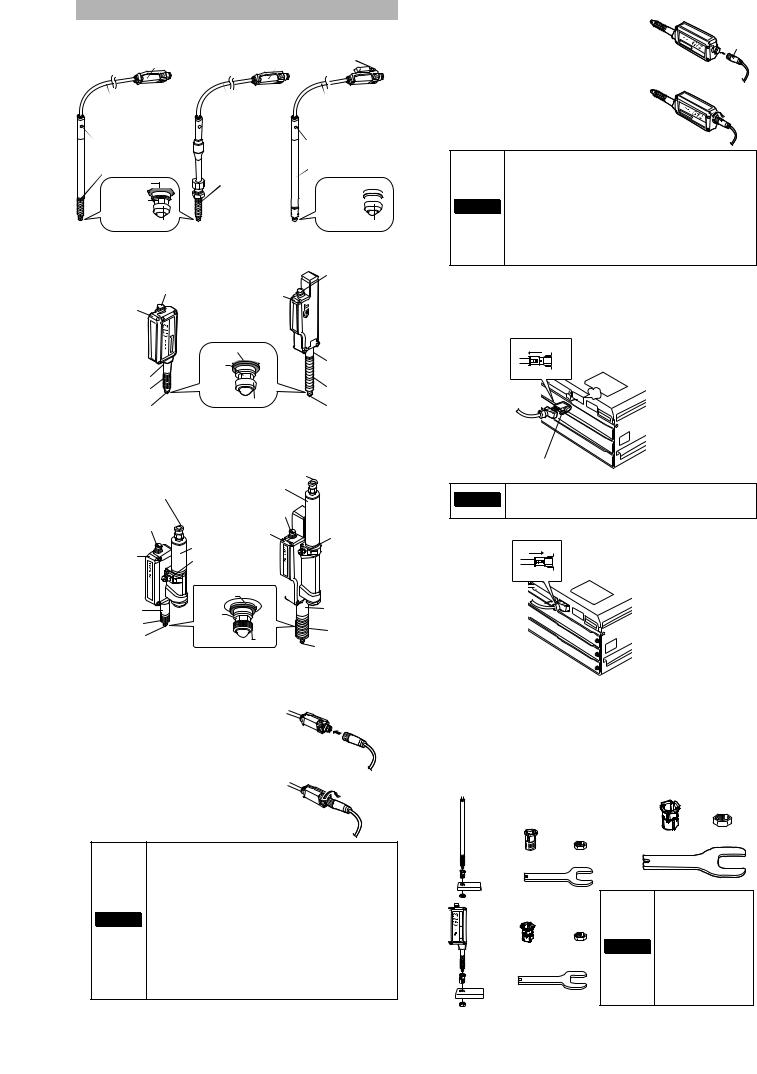
Connecting and Mounting the Sensor Head
■ Names of parts of the sensor head
●GT2-P12K(L)/P12(L) ●GT2-P12KF/P12F ●GT2-PA12K/PA12
Relay connector |
|
Relay connector |
Cable |
|
Cable |
Cable between connector |
Cable |
connector |
the sensor |
between the |
|
head and relay |
sensor head |
|
connector |
and relay |
|
|
connector |
|
Operation indicator |
Operation indicator |
|
Mounting fixture
 Dust boot*
Dust boot |
Dust boot |
Spindle
Dust seal 
Contact
* Not included in the GT2-P12KL/P12L.
Air supply hole
 Cable Cable between connector the sensor
head and relay connector
Operation indicator
Mounting fixture
Spindle 


Contact
● GT2-H12K(L)(F)(LF)/H12(L)(F)(LF)/H32(L)/H50
|
|
|
Cable connector |
|
Cable connector |
Head indicator |
|
Head indicator |
|
|
|
|
Dust boot |
|
|
Bracket fixing |
Spindle |
|
Bracket fixing |
|
part |
||
|
|
||
part*1 |
|
|
|
Dust boot*2 |
|
|
Dust boot*3 |
Contact |
|
Contact |
Contact |
|
|
||
*1 A mounting bracket is attached to |
*3 Not included in the GT2-H32L. |
||
GT2-H12KF/H12F/H12KLF/H12LF. |
|
|
|
*2 Not included in the GT2-H12KL/H12L/H12KLF/H12LF. |
|
||
● GT2-A12K(L)/A12(L)/A32/A50 |
|
||
|
|
Coupling socket |
|
Coupling socket |
Air cylinder |
|
|
|
|
||
|
|
Cable connector |
|
Cable connector |
Head indicator |
|
|
|
Exhaust valve |
||
|
|
|
|
|
Air cylinder |
|
|
Head indicator |
Exhaust valve |
|
|
|
|
|
|
|
Dust boot |
|
|
Mounting fixture |
Spindle |
|
Mounting fixture |
|
|
|
|
Dust boot* |
|
|
Dust boot |
Contact |
|
Contact |
|
|
|
||
|
|
|
|
|
|
|
Contact |
*Not included in the GT2-A12KL/A12L.
■Connecting the sensor head connection cable
● For GT2-P***/PA***
1 Insert the sensor head connection cable into the cable connector on the relay connector cable.
2 Secure the connector with the sensor head connection cable screw.
•When connecting the connector, be sure to insert it straight, and tighten it securely. (Recommended tightening torque: 0.4 to 0.5 N•m*)
If the connection is not tight enough, the connector may be loosened by vibration or other causes, leading to a connection failure.
(* After tightening it firmly by hand, use pliers or
NOTICE other tools to rotate it about 30° for further tightening.)
•When the head is attached to a moving part, and the cable will be repeatedly bent, ensure that the cable between the sensor head and relay connector does not bend. Instead, bend the sensor head cable connecting the relay connector and the amplifier.
● For units other than GT2-P***/PA***
1 Insert the sensor head connection cable into the cable connector of the
sensor head.
Arrow
2 Secure the connector by rotating the grooved portion of the sensor head connection cable.
•When connecting the connector, be sure to insert it without tilt, and tighten it securely. (Recommended tightening torque: 0.4 to 0.5 N•m*)
If the connection is not tight enough, the connector
may be loosened by vibration or other causes, NOTICE leading to a connection failure.
(* After tightening it strongly by hand, use pliers or other tools to rotate it about 30° for further tightening.)
•The M8 L-shaped connector (GT2-CHL*M) cannot be used with the GT2-H32(L)/H50/A32/A50.
•To disconnect the sensor head connection cable, reverse the steps above.
■ Connecting the amplifier
1 Remove the lock cover of the connector of the sensor head connection cable, and insert the sensor head connection cable into the connector on the back of the amplifier until it clicks.
Lock cover
Unlocked
click
Orient the connector so that the lock lever is on the right side.
To disconnect the sensor head connection cable, NOTICE press and hold the lock lever on the side of the
connecter and disconnect the cable.
2 Put the lock cover on the connector, and lock the lock cover.
Lock cover
Locked
■ Mounting the sensor head
●Mounting directly to a jig
Before mounting the sensor head directory to a jig, create a hole on the jig. Attach the sensor head using the optional head mounting bracket sold separately. A mounting bracket is provided with the GT2-P12KF/ P12F/H12K(L)F/H12(L)F as standard. Attach it with the supplied nut.
Mounting |
● GT2-P12K(L)/P12(L)/PA12K/PA12/ |
● GT2-H32(L)/H50/A32/A50 |
|||
illustration |
H12K(L)/H12(L)/A12K(L)/A12(L) |
|
Options of the head mounting |
||
|
|
|
|
bracket D (OP-84327) |
|
|
Options of the head mounting |
|
|
|
|
|
bracket A (OP-76874) |
|
|
|
|
|
|
|
|
Tightening sleeve |
Nut |
|
Tightening sleeve |
Nut |
|
|
|
|
|
|
|
Key wrench |
|
|
Key wrench |
|
|
When mounting the |
|
|
Options of the head mounting |
|
|||
|
|
GT2-H32L facing |
|||
|
bracket C (OP-84396) |
|
|
||
|
|
|
upward, be sure to |
||
|
|
|
|
||
|
|
|
|
use the mounting |
|
|
|
|
|
holes on the side of |
|
|
Tightening sleeve |
NOTICE |
the sensor head. If |
||
|
Nut |
|
the sensor head is |
||
|
|
|
|
||
|
|
|
|
mounted using head |
|
|
|
|
|
mounting bracket D, |
|
|
|
|
|
the spindle may not |
|
|
Key wrench |
|
|
fully extend. |
|
5 |
GT2-100-M-E |
Loading...