


GL-R
Table of contents
 Loading...
Safety Light Curtain
DANGER
NOTICE
DANGER
DANGER
96M12000
DANGER
DANGER
DANGER
GL-R Series
Instruction Manual
Detailed information about functions and use of the GL-R series is also described in the "GL-R Series
User's Manual", and the configuration software of "Safety Device Confi gurator" is needed to use all
functions of the GL-R. In order to acquire the "GL-R Series User 's Manual" and "Safety Device
Configurator", download them from the KEYENCE website or call the nearest KEYENCE office.
<KEYENCE website> http://www.keyence.com
This Instruction manual describes handling, operation, and precautionary information for the GL-R
Series Safety Light Curtain ("GL-R").
Read this Instruction manual thoroughly before operating the GL-R in order to understand the device
features, and keep this Instruction manual readily available for reference. Ensure that the end user of this
product receives this manual.
In this Instruction manual, "GL-RF" represents the finger protection type with the detection capability of
14 mm, "GL-RH" represents the hand protection type with the detection capability of 25 mm, "GL-RL"
represents the body protection type with the detection capability of 45 mm and "GL-R" represents all
the models including the GL-RF, GL-RH and GL-RL.
This manual is the original instruction manual.
Symbols
The following symbols alert you to important messages. Be sure to read these messages carefully.
It indicates a hazardous situation which, if not avoided, will result in death or serious
injury.
It indicates a situation which, if not avoided, could result in product damage as well as
property damage.
It indicates additional information on proper operation.
Point
It indicates tips for better understanding or useful information .
Reference
Indicates reference pages in this or another manual.
Safety Information for GL-R Series
General precautions
• You must verify that the GL-R is operating correctly in terms o f functionality and
performance before the start of machine and the operation of the GL-R.
• KEYENCE does not guarantee the function or performance of the GL-R if it is used in a
manner that differs from the GL-R specifications contained in this user's manual or if
the GL-R is modified by the customer.
• When using the GL-R to protect machine operators against a hazard or hazardous zone
or using the GL-R as a safety component for any purpose, always follow the applicable
requirements of the laws, rules, regulations and standards in the country or region
where the GL-R is used. For such regulations, you should directly contact to the
regulatory agency responsible for occupational safety and health in your country or
region.
• Depending on the type of machine on which the GL-R is to be installed, there may be
special safety regulations related to the use, installation, maintenance, and operation of
the safety component. In such a case, you must fulfill such safety regulations. The
responsible personnel must install the GL-R in strict compliance with such safety
regulations.
• The responsible personnel must do the training to the assigned personnel for the
correct use, installation, maintenance, and operation of the GL-R. "Machine operators"
refers to personnel who have received appropriate training from the responsible
personnel and are qualified to operate the machine correctly.
• Machine op erators must have specialized training for the GL-R, and they must
understand and fulfill the safety regulations in the country or region in which they are
using the GL-R.
• When the GL-R fails to operate, machine operators must immediately stop the use of the
machine and the GL-R and report this fact to the responsible personnel.
• The GL -R is designed with the assumption that it would be correctly installed in
accordance with the installation procedures described in this user's manual and
correctly operated according to the instructions in this user's manual. You must
perform an appropriate installation of the GL-R after performing a sufficient risk
assessment for the target machine.
• Be sure to absolutely confirm that there is nobody in the hazardous zone, before you
remove the GL-R from the machine for replacement or disposal.
• When disposing the GL-R, always follow the applicable requirements of the laws, rules,
regulations and standards in the country or region where t he GL-R is used.
• The GL -R should be processed as an industrial waste product when being disposed.
Precaution on use
Operators
• In order to operate the GL-R correctly, the responsible personnel and machine operators
must fulfill all of the procedures described in this user's manual.
• No person other than the responsible personnel and machine operators should be
allowed to install or test the GL-R.
• When performing electrical wiring, always fulfill the electri cal standards and regulations
for the country or region in which the GL-R is used.
Environment of use
• Do n ot use the GL-R in an environment (temperature, humidity, interfering light, etc.)
that does not conform to the specifications contained in this user's manual.
• Be s ure to confirm that the GL-R keeps normal operation when electromagnetic
radiation is generated by wireless devices. (If you use wireless devices such as cellular
phones or transceivers in the vicinity of the GL-R.)
• The GL-R is not designed to be explosion-proof. Never use it in the presence of
flammable or explosive gases or elements.
• Be sure to confirm no deterioration in product quality if you use the GL-R in the
presence of substances, such as heavy smoke, particu late matter, or corrosive chemical
agents.
• Do n ot install the GL-R in areas where the GL-R is exposed to intense in terference light
such as direct sunlight, and direct or indirect light from an inverter-type fluorescent
lamp (rapid-start type lamp, high-frequency operation type lamp, etc).
• Be sure to absolutely confirm that there is nobody in the hazardous zone, before the
interlock is released (i.e. the machine system restarts) by the interlock reset
mechanism. Failure to follow this warning results in significant harm to the machine
operators, including serious injury or death.
• Be sure to absolutely confirm that there is nobody in the hazardous zone before the
override function is activated. Failure to follow this warning results in significant harm
to the machine operators, including serious injury or death.
Tar g et m a chi n e
• The GL-R has not undergone the model certification examination in accordance with
Article 44-2 of the Japanese Industrial Safety and Health Law. The GL-R, therefore,
cannot be used in Japan as a "Safety Device for Press and Shearing machines" as
established in Article 42 of that law.
• The machine on which the GL-R is to be installed must be susceptible to an emergency
stop at all operating points during its operation cycle. Do not use the GL-R for machines
with irregular stop times.
• Do n ot use the GL-R for power presses equipped with full-revolution clutches.
• The GL-R cannot be used as a PSDI because it does not fulfill the requirements of OSHA
1910.217(h). Refer to OSHA 1910.217 for the PSDI mode.
• Do not use the GL-R to control (stop forward motion, etc.) trains, cars and other
transportation vehicles, aircraft, equipment for use in space, medical devices, or
nuclear power generation systems.
• The GL-R is designed to protect people or objects from going into/approaching
detection zone against machine's hazard or hazardous zone. It cannot provide
protection against objects or materials that are expelled from the machine's hazard or
hazardous zone, so you must establish additional safety measures such as installing
safeguards when there is the possibility of such projectiles.
Installation
• The GL-R must be installed only after ensuring the minimum safety distance between
the GL-R and the hazardous zone or hazard as established by the applicable regulations
in the country or region in which the GL-R is used. (e .g. EN ISO13855 (ISO 13855) in EU
countries)
• Cho ose locations for the installation of the GL-R transmitters and receivers so that they
are not subject to the effects of light reflected from glossy surfa ces in the area.
• Corre ct operation and detection is not possible if the receiver has a different beam axis
spacing (detection capability) from that of the transmitter. You must verify that the beam
axis spacing (detection capability) is the same between the transmitter and the receiver
when installing the GL-R.
• The G L-R must be installed so that the machine operator is able to go into or approach
the hazardous zone or hazards only by passing through the detection zone of the GL-R.
Strictly avoid installation that allows the machine operator or a part of the machine
operator's body to go into or approach the hazardous zone or hazards without passing
through the protective zone of the GL-R or to remain in position between the protective
zone of the GL-R and the hazardous zone or hazard. In a case w here you install the GL-R
units in series (series connection), you must always check the installation carefully
whether you follow this warning, especially after installation and maintenance.
• You must always perform the pre-check tests after installing the GL-R in accordance
with the pre-check test procedures, such as items specified in this user's manual, in
order to verify that the test pieces can be detected in all of t he detection zones.
• Inte rlock reset mechanisms (such as switches) must be installed so that the entire
hazardous zone can be checked by the responsible personnel. Interlock reset
mechanisms should not be accessible from within the hazardous zone.
• Mut ing is a function to allow a temporary automatic suspension of the GL-R safety
functions while the GL-R is receiving a signal from muting devices (such as sensors or
switches). Therefore, additional safety measures are required for the machine on which
the GL-R is installed in order to ensure safety while the muting is activated.
• Mut ing devices, the installation of those devices and the procedure to activate the
muting function must fulfill the conditions specified in this user's manual and the
requirements of the laws, rules, regulations and standards in the country or region in
which the GL-R and those devices are used. Failure to follow this warning may result in
significant harm to the machine operators, including serious injury or death .
• When you install muting devices (such as sensors or switches) for muting, the following
conditions must be fulfilled.
(1) Muting devices must be installed so that the muting cannot be activated if the
hazardous zone of the machine is in an unsafe condition or cycle.
(2) Muting devices must be installed so that the muting cannot be activated even if the
personnel is accidentally approaching the detection zone of the GL-R.
• The muting device must be installed such that only responsible personnel have access
to that device to change the installation or orientation. Special tools must be required to
ensure that only responsible personnel are capable of installation, orientation or change
of muting device.
• Only the responsible personnel may be allowed to install or wire the devices to activate
the muting function.
• The installat ion of a muting lamp may be required by the laws, rules, regulations, and
standards in the country or region in which the GL-R is used if you apply the muting
function. It depends on the machine application and/or the result of your risk
assessment. If it is necessary for you to provide a muting lamp, you must fulfill the
requirements because you are fully responsible for installation of the muting lamp.
• The override is a function to allow a temporary manual suspension of the safety
functions of the GL-R. Therefore, additional safety measures are required for the entire
machine system on which the GL-R is installed in order to ensure safety while the
override is activated.
• The override devices, the installation of those devices and the procedures to activate
the override must fulfill the conditions specified in this manual as well as the
requirements of the laws, rules, regulations and standards in the country or region in
which the GL-R and those devices are used. Failure to follow this warning may result in
significant harm to the machine operators, including serious injury or death .
• The override devices, which are used for activation of override, must be manual
operating devices. When installing the devices to activate the override, those devices
must be installed so that the whole hazardous zone can be checked by the responsible
personnel and so that it is not possible for machine operators to operate those devices
in the hazardous zone.
1
E GL-R-IM
DANGER
• The installa tion of the indication for override may be required by the laws, rules,
DANGER
DANGER
regulations, and standards in the country or region in which the GL-R is used if you
apply the override function. It depends on the machine application and/or the result of
your risk assessment. If it is necessary for you to provide the indication for override,
you must fulfill the requirements because you are fully responsible for installation of the
indication for override.
• The customer is fully responsible for complying with the requirements for muting and/or
override. Those who use muting and/or override must fulfill all of the requirements
related to muting and/or override. KEYENCE accepts NO responsibility and NO liability
for any damage or any injury due to the unauthorized installation, usage or
maintenance, which are not specified in this user's manual, and/or due to
noncompliance with the laws, rules, regulations and standards in the country or region
in which the GL-R is used.
• W hen the reduced resolution function is applied, the detection capability varies
according to your configuration. Make sure to accurately calculate the safety di stance
according to the detection capability, and install the GL-R at a distance greater than or
equal to the minimum safety distance away from the hazardous zone or hazard. The
installation of additional safety measures, such as safeguarding, may be required if the
detection capability varies due to the configuration of reduced resolution. On your own
responsibility, you must perform the risk assessment based on your configuration of
reduced resolution in order to reduce the risk.
• When the fixed blanking function is applied, a hazardous clearance that is not protected
by the GL-R may be generated between the obstacle and the GL-R. You must install an
additional safety measure such as a safeguard for this clearance.
• S ecurely tighten mounting brackets and cable connectors used for the installation of
the GL-R in accordance with the torque values specified in this user's manual.
• When optical synchronization system is applied and Channel A or B is configured, the
response time is longer than the other c ase. Make sure to accurately calculate the safety
distance according to the response time, and install the GL-R at a distance greater than
or equal to the minimum safety distance away from the hazardous zone or hazard.
Circuit design and wiring
• Always turn off t he power to the GL-R when performing electrical wiring.
• You must fulfill the electrical standards and regulations in the country or region in
which the GL-R is being used when you perform the electrical wiring.
• To avoid the risk of electric shock, do not connect any of the GL-R inputs to DC power
sources outside of the range of 24 V DC + 20% or to any AC power source.
• To avoid the risk of electric shock, be sure that any hazardous voltage is isolated from
all wiring of the GL-R with reinforced insulation or double insulation.
• In order to fulfill the requirements in IEC61496-1, UL61496-1, EN61496-1 and UL508, the
power supply for the GL-R must fulfill the conditions listed below.
(a) A rated output voltage of 24 V DC (SELV, Overvoltage Category ) within ±20%.
(b) Double insulation or reinforced insulation between the primary and secondary
circuits.
(c) Output holding time of 20 ms or more.
(d) A power supply must fulfill the requirements of the electrical safety and
electromagnetic compatibility (EMC) regulations or standards in all countries
and/or regions where the GL-R is used.
(e) A secondary circuit of power supply (output) must fulfill the requirements for
Class 2 Circuits or Limited Voltage/Current Circuits specified in UL508, if the
GL-R is used in the United States or Canada.
• Do not insta ll the electric wiring of the GL-R together with or in parallel with any highvoltage electrical or power lines.
• Bot h OSSD outputs provided on the GL-R must be used to establish a safety-related
machine control system. Establishing a safety-related machine control system with just
one of the OSSD outputs cannot stop the machine due to an OSSD output malfunction
and may result in significant harm to the machine operators, including serious injury or
death.
• W hen using PNP output type cables, do not cause a short-circuit between the OSSD and
+24V. Otherwise, the OSSDs keep staying at the ON-state and it causes a dangerous
situation.
• When using PNP output type cables, be sure to connect the load between the OSSD and
0V to avoid a dangerous situation. If the load is incorrectly connected between th e
OSSD and +24V, the logic of the OSSD operation will be reversed and the OSSD will
change to an ON state when the GL-R detects an interruption in the detection zone. This
is a dangerous situation.
• When using NPN output type cables, do not cause a short-circuit between the OSSD and
0V. Otherwise, the OSSDs keep staying at the ON-state and it causes a dangerous
situation.
• W hen using an NPN output type cable, be sure to connect the loa d between the OSSD
and +24V to avoid a dangerous situation. If the load is incorrectly connected betwe en
the OSSD and 0V, the logic of the OSSD operation will be reversed and the OSSD will
change to an ON state when the GL-R detects the interr uption in the detection zone.
This is a dangerous situation.
• Regardless of whether the cables are PNP or NPN type, you must fulfill the requirements
of Clause 9.4.3 in IEC60204-1: 2005 for protection against maloperation due to earth
fault.
• All outputs, other than OSSDs, are not allowed to be used as safety outputs for a safetyrelated machine control systems. Usage of these functions as safety outputs may result
in significant harm to the machine operators, including serious injury or death.
• The wait input is not allowed to be connected to the output from any components
comprising a part of the safety-related machine control system. If the wait input is
connected to the output of a safety component it may result in significant harm t o the
machine operators, including serious injury or death.
• Th e transmitter and receiver cables must be within the lengths specified in this user's
manual. Usage of cables longer than the specified length may cause the improper
operation of safety functions and may cause a dangerous situation.
Testing and maintenance
• You must always perform the pre-check test in accordance with the checklist, after
maintenance, adjustment or alignment of the target machine or the GL-R and before the
machine startup.
• If the GL-R does not operate properly when you perform a pre-check test in accordance
with the checklist specified in this user's manual, do not operate the machine.
• You must periodically examine the machine to verify that all brakes, other stop
mechanisms, and control devices operate reliably and correctly in addition to checking
the GL-R.
• The responsible personnel must perform maintenance procedures as specified in this
user's manual to ensure safety to the machine and GL-R.
Precautions on regulations and standards
CE Marking
KEYENCE Corporation has confirmed that this product complies with the essential requirements of
the applicable EC Directive, based on the following specifications.
Be sure to consider the following specifications when using this product in a member state of the
European Union.
• Machinery Directive (2006/42/EC)
The GL-R is a safety component as established by the European Union's Machinery Directive
(2006/42/EC) Annex V. The GL-R complies with the following EN Standards and has been certified
by TÜV SÜD Product Service GmbH.
• EN61496-1 Type 4 ESPE
• EN61496-2 Type 4 AOPD
• EN50178
• EN61508, Part 1 to 4 SIL3
• EN62061 SIL CL3
• EN ISO13849-1 Category4, PLe
• EMC Directive (2004/108/EC)
The GL-R complies with the following EN Standards
• EN55011 Class A
• EN61496-1 Type 4 ESPE
These specifications do not give any guarantee that the end-product with this product incorporated
complies with the essential requirements of EMC Directive. The manufacturer of the end-product is
solely responsible for the compliance of the end-product itself according to the EMC Directive.
UL Certificate and North American Regulations
The GL-R complies with the following North American and international standards and has received
UL certification and C-UL certification. (CCN: NIPF/NIPF7, File No:E184802)
• UL61496-1 Type 4 ESPE
• UL61496-2 Type 4 AOPD
• UL508
• UL1998
The GL-R also complies with the following North American regulations.
• FCC Part 15B Class A Digital Device
• ICES-003 Class A Digital Apparatus
Model Certification Examination as a "Safety Devices for Presses and
Shearing Machines"
The GL-R has not obtained the model certification examination in accordance with Article 44-2 of the
Japanese Industrial Safety and Health Law. Therefore, the GL-R cannot be used in Japan as a
"Safety Devices for Presses and Shearing Machines" as established in Article 42 of that law.
Other standards
The GL-R has been designed in consideration of the following standards and regulations. For details
regarding the following standards, contact the third-party certification organization, such as UL or
TÜV.
• EN60204-1
• EN692
• EN693
• OSHA 29 CFR 1910.212
• OSHA 29 CFR 1910.217
• ANSI B11.1 - B.11.19
• ANSI/RIA R15.06 - 1999
• SEMI S2
• "Guidelines for Comprehensive Safety Standards of Machinery", July 31, 2007, number 0731001
issued by Ministry of Health, Labor, and Welfare in Japan.
Standard set
• GL-R transmitter (Transmitter) x 1
• GL-R receiver (Receiver) x 1
• Test piece x 1
GL-RF : With diameter of 14 mm and length of 200 mm
GL-RH : With diameter of 25 mm and length of 200 mm
GL-RL : The test piece (diameter: 45 mm) is not supplied. Please acquire on your own.
• Instruction manual (this document) x 1
E GL-R-IM
2
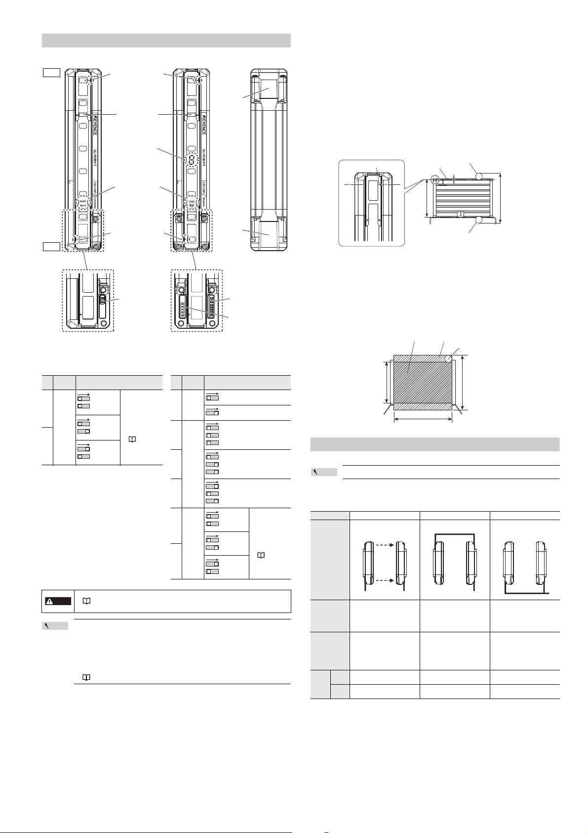
Part Description
Point
DANGER
Transmitter
Beam center-line mark
Receiver Back side
Center Indicators
7-segment display
Function indicators
Beam center-line mark
Setting switch
(2 switches)
Setting switch
(6 switches)
Connector for the
interface unit
(GL-R1UB)
Top
Bottom
End cover
Connector
for the unit
connection
cable
Transmitter Receiver
Switch
No.
Function Configuration
2
Channel
Channel 0
(Not applied)
(Default)
Use Channel for
light interference
prevention when
optical
synchronization
system is applied.
For details, refer to
the "Light
interference
prevention function"
(page 5).
Channel A
1
Channel B
2
Switch
No.
Function Configuration
6
Center
indicator
ON (Green) when all beam axes
are clear (Default)
OFF when all beam axes are clear
(Green OFF)
5
Reduced
resolution
(Safetyrelated
function)
Reduced resolution is not ap plied
(Default).
4
Reduced resolution (one optical
beam) is applied.
3
Reduced resolution (two optical
beams) is applied.
2
Channel
Channel 0
(Not applied)
(Default)
Use Channel for
light interference
prevention when
optical
synchronization
system is applied.
For details, refer to
the "Light
interference
prevention function"
(page 5).
Channel A
1
Channel B
5
43
2
Beam center-line mark
Beam center-line
Specified target detection
capability (position A)
Protection
height
Specified target detection
capability (position B)
Detection
height
a: Beam axis spacing
b: Beam axis diameter
c: Detection capability
a
b
c
Detection zone Protection zone
Specified target detection capability
Detection height Protection height
Operating distance
Beam center-line : An optical path joining the optical center of the emitting element on the transmitter to
Detection height : The height from the top beam center-line to the bottom beam center-line (length).
Protection height : An object approaching the detection zone from the top of the detection height is first
* Refer to the following diagram for an explanation of beam center-line, detection height and protection
height.
the optical center of the corresponding receiving element on the receiver. The GL-R
must be installed so that the beam center-line mark on the transmitter and that on
the receiver face one another and are located at the same height.
detected at point A, which is the distance of the detection capability from the top of
the detection height. The equivalent position on the bottom is called point B. The
height from the top edge of the specified target detection capability that exists at
point A to the bottom edge of the specified target detection capability that exists at
point B is called The "protection height".
The following calculation formula can be defined:
Protection height = "Detection height" + ( 2 x "the specified target detection
capability" ) – "beam axis diameter".
* The side where the end cover has already been installed at shipment is the top side.
Setting switch
2
1
2
1
Detection zone : The zone in which the specified target detection capability can be detected. The
Protection zone : The square area formed with the protection height and the operating distance,
* Refer to the following diagram for detection zone and protection zone.
6
detection zone of the GL-R indicates a square area formed with the detection height
and the operating distance. When an object of the specified target detection
capability is present in this area, the light of the GL-R is blocked, and then the
OSSD goes to OFF state.
which is broader than the detection zone. When an object of the specified target
detection capability is present in this area, the light of the GL-R is blocked, and then
the OSSD goes to OFF state.
Functions and Features
5
43
5
43
2
1
2
1
The functions and features of the GL-R are described in this section.
For more information about these functions, see "GL-R Series User's Manual".
Point
Wiring system
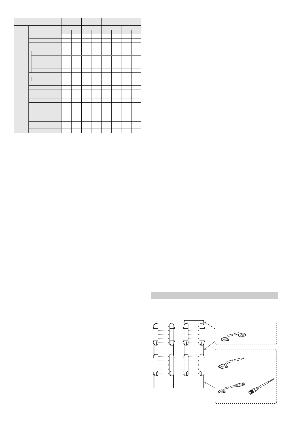
The following three types of wiring systems are available in the GL-R series.
Wiring system Optical synchronization system One-line system Wire synchronization system
Wiring diagram
Transmitter Receiver Transmitter Receiver Transmitter Receiver
• The response time varies according to the configuration of Channel.
"Response time (OSSD)" (page 9)
• The det ection capability varies according to the configuration of reduced res olution.
• The configuration of the setting switch is applied when the power is supplied.
• When th e GL-R is in series connection, the setting switch configuration of the main unit
is applied regardless of the setting switch configuration of the sub unit.
• When th e center indicator and reduced resolution are configured by using the
configuration software, the setting switch must be configured by default. Otherwise an
error occurs.
• When th e GL-R operates in wire synchronization system, the setting switch for Channel
must be configured by default. Otherwise an error occurs.
"Wiring system" (page 3)
• Simplified wiring.
• The unit connection cable is
not needed for the transmitter.
• The input and output functions
on the transmitter are not
available.
• There is a maximum limit for
the total length of cables.
5-core cable
11-core cable
Advantage
Limitation
Applicable
cable
• Wiring is not needed be tween
the transmitter and receiver.
• The Transmitter and the
receiver can operate on
different power supplies.
• The input and output functions
on the transmitter are not
available.
• All indicators other than
"Power" are not available on
the transmitter.
Transmitter
5-core cable Series connection cable
5-core cable
Receiver
11-core cable
3
• All functions of the GL-R are
available.
• Wiring is needed between the
transmitter and the receiver.
7-core cable
11-core cable
7-core cable
11-core cable
E GL-R-IM
Wiring system
Optical/wire
synchronization system
One-line
system
Series connection cable
Unit connection cable
Unit connection cable (for extension
use) + Extension cable
* The unit connection cable can not be
connected on the upper part of the GL-R.
Cable for the transmitter 5-core
Cable
combination
Cable for the receiver
OSSD output
AUX (auxiliary) output
Error output
Muting function
Partial muting function
Muting bank function
Muted condition output
Muting lamp output
Override function () ()
Interlock function () () () ()
Available
function
: Available without the configuration software
: Available with the configuration software
() : Available without the configuratio n software, Functionality can be expanded when using the configuration software.
Interlock-reset-ready output
EDM function () () () ()
Wait input
Alert output
Clear/Block output
Reset input (for error)
Reduced resolution function () () () () () () () ()
Fixed blanking function
Channel configuration
(Light interference
prevention function)
Center indicator
configuration
Monitoring function
Optical
synchronization
5-core 11-core 5-core 11-core 7-core 11-core 7-core 11-core
() () () () () () () ()
One-line Wire synchronization
Series connection
7-core 11-core
Series connection
Up to three GL-R units can be serially connected and used as a single light curtain.
OSSD
The OSSD is a safety-related control output. It connects to an external device (load), such as an FSD or
MPCE. The GL-R generates self-diagnosis signals on its internal control circuit to perform diagnostics on
the output circuit (OSSD). These signals periodically force the OSSD into a temporary OFF state when
no interruption exists in the detection zone.
Interlock function
Interlock is a function that prevents the OSSD from automatically going to the ON state from an OFF
state.
You can prevent the unintended start-up and/or the unintended restart of the machine if an interlock is
applied to the GL-R.
External device monitoring (EDM function)
EDM (External Device Monitoring) is a function of the GL-R that monitors the state of the control devices
which are externally connected to the GL-R. The GL-R can detect a fault, such as welded contacts on
external devices, as long as the EDM function is activated.
This function is available only when connecting the 11-core cable to the receiver.
Fixed Blanking
During normal operation, the OSSD remains in the ON state while the GL-R detects no interruption in the
detection zone, and the OSSD goes to the OFF state when the GL-R detects interruption in the detection zone.
On the other hand, if fixed blanking is enabled on certain beam axes, the OSSD remains in the ON state
as long as the GL-R detects interruption on those beam axes and no interruption elsewhere in the
detection zone.
Reduced resolution
During normal operation, the OSSD goes to the OFF state when the GL-R detects interruption in the
detection zone.
On the other hand, if reduced resolution is enabled on the GL-R with the number of beam axes to be
ignored and not monitored specified, the OSSD remains in the ON state even while the GL-R detects
interruption on certain beam axes as long as the total number of interrupted beam axes is less than or
equal to the number of ignored beams.
Muting Function
The muting function is used to temporarily suspend the GL-R's safety functions while the GL-R receives
a signal from muting devices (such as sensors or switches). Before this function can be used, the outputs
from the muting devices must be connected to the muting input terminal on the GL-R.
In addition, the configuration software provides the user with the opportunity to select the beam axes to
be in the muted condition. You can minimize the number of beam axes to be in the muted condition by
using the configuration software. Therefore, you can reduce the risk of interrupting the hazardous zone.
Muting device
When using the muting device, it must be met with the following conditions.
• The muting device output must be N.O. (normally open).
• Output of the muting device must be the output with contacts, and must be PNP output type if PNP
output type cable is used, or NPN output type if NPN output type cable is used. Also, the muting
device must be capable of 2 to 3 mA current.
• Do not use one muting device with multiple outputs in place of two or more muting devices. (Only
one output per one muting device must be used.)
• If the muting device has a timer function that can adjust the output timing, do not use that function.
Muting lamp
When using the muting lamp, it must meet the following conditions.
For an incandescent lamp : rated 24 V DC, 1 to 5.5 W
For an LED indicator : rated current consumption must be 10 to 230 mA.
Conditions for initiation of muting
Muted condition is initiated if all of the following conditions are met:
• Muting input 2 turns ON within 0.04 to 3 seconds after muting input 1 turns ON
• GL-R detects no interruption in the detection zone
• OSSD is in the ON state and remains for 0.5 seconds or more.
E GL-R-IM
Conditions for termination of muting
Muted condition is terminated if one of the following conditions is met:
• Either of the muting inputs goes to the OFF state for at least 5 ms.
• Light curtain goes into the error condition
• Wait input goes to ON state
• The power supply is interrupted or restored.
• Maximum muting period of approx. 5 minutes has been passed.
Changing of conditions for muting
The following muting conditions can be changed through the configuration software or a special
procedures.
Condition for Initiation of muting
1. Time period specification of 0.04 s to 3 s between muting input 1 and muting input 2 can be option.
2. Sequence specification of muting inputs can be option. (Default sequence: muting input 1 is first,
muting input 2 is second.)
Condition for termination of muting
3. Time period specification form muting input OFF to termination of muted condition. (Default is 0
seconds.)
4. Maximum muting period of approx. 5 minutes can be option.
Condition for muting lamp
5. Error condition can be initiated if muting lamp has some failure.
If you choose these options according to your machine application, password setting and/or password
input is required as a special procedure.
The responsible personnel who intends to apply these options mentioned above from 1 to 4 have to
perform the risk assessment based on the machine application.
Muting bank function
The muting bank function can be activated through the configuration software.
You can configure up to three muting banks on the GL-R. Each muting bank is a group of beam axes that
will go into a muted condition upon activation of muting.
In order to activate a muting bank, you must switch (ON and OFF) the muting bank input.
Override function
During normal operation, the OSSD goes to an OFF state if the muting function is deactivated and an
interruption remains in the detection zone of the GL-R. The OSSD OFF state will remain until the
obstruction is removed.
Override function allows a temporary manual suspension of the GL-R safety functions.
This makes it possible to remove the obstruction remaining in the detection zone of the GL-R. (Machine
is able to be manually operated on a temporary basis because the safety function of the GL-R is
temporarily suspended.)
Conditions for initiation of override
Override function is initiated if all of the following conditions are met and the wait input goes to the ON
state within 0.04 s to 1 s after the override input turns ON state.
• GL-R is not in the error condition.
• GL-R detects interruption in the detection zone. (One or more beam axis is blocked.)
• OSSD is OFF state. (including interlock condition)
• Either of muting inputs, or both, turns ON state
Conditions for termination of override
Override function is terminated if one of the following conditions is met:
• All of muting inputs turn OFF.
• Either the override input or wait input, or both, turn OFF.
• Light curtain goes to into the error condition
• Maximum override period of approx. 60 seconds has been passed.
Changing of the condition for override
The following condition can be changed through the configuration software.
Conditions that deactivate the override condition
• Maximum override period of approx. 60 seconds can be option.
If you choose this option according to your machine application, password setting and/or password input
is required. The responsible personnel must securely manage the password. The responsible personnel
who intends to apply this option must perform the risk assessment based on the machine application.
Installation
Overview
4
Loading...