


 Loading...
96141E
Digital Fiber Sensor
FS-N10 Series
User's Manual
Read this manual before use.
Keep this manual in a safe place for future reference.
Introduction
This manual describes the basic operations and hardware functions of the FS-N10 Series. Read the manual carefully to ensure safe performance and function of the FS-N10 Series. Keep this manual in a safe place for future reference.
Ensure that the end user of this product receives this manual.
Symbols
The following symbols alert you to matters concerning the prevention of injury and product damage.
Failure to follow the instructions may lead to death or serious
DANGER
injury.
WARNING |
Failure to follow the instructions may lead to injury. |
Failure to follow the instructions may lead to product damage or
CAUTION
failure of the product.
Point
Provides additional information on proper operations.
 Provides advanced and useful information for operation.

Safety Precautions
Hints on Correct Use
•Do not use this product in safety circuits for human protection.
•This product is not explosion-proof. Do not use the product in

 WARNING places with flammable gas, liquid, or dust.
•This product uses DC power. Do not apply AC power. The product may explode or burn if an AC voltage is applied.
•Do not wire the amplifier line along with power lines or high-tension lines, as the sensor may malfunction or be damaged due to noise.
•When using a commercially available switching regulator, ground the frame ground terminal and ground terminal.
•Do not use the FS series outdoors, or in a place where extraneous light can enter the light receiving element directly.
•Due to individual dispersion characteristics and the difference in fiber unit models, the maximum sensing distance or displayed value may not be the same on all units.
•If the sensor is used for a long time with the APC function enabled and the LED is imposed with a heavy load, the current consumption of the sensor for light emission will become constant and 'END APC' will be displayed. The sensor can still be used in this case. However, replace the sensor if even small changes in received light intensity should be detected for precise detection.
About UL Certification
The FS-N Series is UL and C-UL certified, and is compliant with the UL and CSA standards.
• Applicable standardsUL508 Industrial Control Equipment
CAN/CSA C22.2 No.14-M05 Industrial Control Equipment
•UL File No. E301717
•UL categories: NRKH, NRKH7
•Enclosure Type 1 (based on UL50 standard)
Notes on UL Certification
•The power source used with the FS-N Series must be UL Listing certified for Class 2 output as stipulated by US National Electric Code (NEC) NFPA70.
•Power supply/Control input/Control output shall be connected to a single Class 2 source only.
•Connect the FS-N12 and N14 to the FS-N11 and N13 main units for use.
•Use with the over current protection device which is rated 30V or more and not more than 1A.
96141E |
1 |

Safety Precautions
MEMO
2 |
- Digital Fiber Sensor FS-N10 Series User's Manual - |

Manual Organization
1

2

3

4

5

6

Before Using
Installation and
Connection
Basic Operation
Settings for Advanced Functions
Specifications
Appendix
Outlines the package contents and identifies part names and functions.
Provides procedures for installing sensor amplifiers and cables, as well as operating precautions.
Explains basic instructions for operating and setting the sensor amplifiers.
Describes settings for advanced functions of the FS-N10 Series.
Provides the specifications, circuit diagrams and dimensions of the FS-N10 Series.
Provides the troubleshooting instructions and initial settings (default values).
1
2
3
4
5
6
<Points for Using This Manual>
• When you "Forgot the operation methods" or "Want to find the operation procedures" Go to pages 3-2, 4-2
•When you "Want to try out the FS-N10"
Go to Chapters 2 and 3
•When you "Want to fully utilize the various functions"
Go to Chapters 3 and 4
•When you "Want to know the meanings of terms used"
Go to Chapter 6 (Index)
•When you "Want to troubleshoot the FS-N10"
Go to Chapter 6 (Troubleshooting)
- Digital Fiber Sensor FS-N10 Series User's Manual - |
3 |

Table of Contents
Safety Precautions............................................................................... |
1 |
Manual Organization ........................................................................... |
3 |
Table of Contents................................................................................. |
4 |
Chapter 1 Before Using
1-1 |
Checking the Package Contents.......................................................... |
1-2 |
|
Sensor Amplifier.............................................................................. |
1-2 |
|
List of Optional Parts....................................................................... |
1-2 |
1-2 |
Part Names.......................................................................................... |
1-3 |
|
Sensor Amplifier.............................................................................. |
1-3 |
|
Display/control unit.......................................................................... |
1-4 |
1-3 |
Model Number Description .................................................................. |
1-5 |
1-4 |
Fiber Units............................................................................................ |
1-6 |
Chapter 2 Installation and Connection
2-1 |
Installing Sensor Amplifiers.................................................................. |
2-2 |
|
Mounting the Sensor Amplifier ........................................................ |
2-2 |
|
Wiring Diagrams for Sensor Amplifiers ........................................... |
2-4 |
2-2 |
Connecting the Fiber Unit .................................................................... |
2-6 |
Chapter 3 Basic Operation
3-1 |
Quick Reference .................................................................................. |
3-2 |
3-2 |
Switching Output.................................................................................. |
3-4 |
|
Output Switch (L-on/D-on) .............................................................. |
3-4 |
3-3 |
Adjusting Sensitivity ............................................................................. |
3-5 |
|
List of Sensitivity Adjusting Methods............................................... |
3-5 |
|
Preset Function ............................................................................... |
3-6 |
|
Work-Preset Function ..................................................................... |
3-7 |
|
Maximum Sensitivity Preset Function ............................................. |
3-8 |
|
Full Auto Preset Function................................................................ |
3-9 |
|
Two-point Calibration..................................................................... |
3-11 |
|
Maximum Sensitivity Calibration ................................................... |
3-12 |
|
Full Auto Calibration...................................................................... |
3-13 |
|
Positioning Calibration................................................................... |
3-14 |
|
Other Calibration Methods ............................................................ |
3-15 |
3-4 |
Setting the Current Received Light Intensity to 0 (Zero Shift)............ |
3-16 |
|
Zero Shift Function........................................................................ |
3-16 |
|
Operating Principle of the Zero Shift Function .............................. |
3-16 |
4 |
- Digital Fiber Sensor FS-N10 Series User's Manual - |

Table of Contents
3-5 Light emission/Received light intensity adjustment (Saturation Canceling)...... |
3-18 |
|
|
Saturation Canceling function ....................................................... |
3-18 |
3-6 |
Loading the Recommended Settings (Recipe Function) ................... |
3-19 |
|
Selecting Recipe ........................................................................... |
3-19 |
|
List of Recipes and Recommended Fiber Units............................ |
3-20 |
3-7 |
Initialization ........................................................................................ |
3-21 |
|
Initialization of Settings (Reset to Initial Values) ........................... |
3-21 |
3-8 |
Locking in MEGA Mode ..................................................................... |
3-22 |
|
MEGA Mode Lock (1-Output Type Only)....................................... |
3-22 |
3-9 |
Disabling the Key Operation .............................................................. |
3-23 |
|
Key Lock........................................................................................ |
3-23 |
|
Key Lock with PIN Number ........................................................... |
3-24 |
Chapter 4 Settings for Advanced Functions
4-1 |
List of Settings ..................................................................................... |
|
4-2 |
||||
4-2 |
Basic Settings ...................................................................................... |
|
4-4 |
||||
|
Power Modes .................................................................................. |
|
4-4 |
||||
|
Sensitivity Setting............................................................................ |
|
4-4 |
||||
4-3 |
Detection Settings (Func) .................................................................... |
|
4-7 |
||||
|
Output Timer ................................................................................... |
|
4-7 |
||||
|
Detection Mode ............................................................................... |
|
4-8 |
||||
|
External Input................................................................................ |
|
4-17 |
||||
|
Writing of External Input to EEPROM ........................................... |
4-19 |
|||||
|
Adjusting Light Emission/Received Light Intensity (Attenuation) ... |
4-20 |
|||||
|
Analog output scaling (FS-N11MN only)....................................... |
4-21 |
|||||
|
Analog scaling mode (FS-N11MN only)........................................ |
4-22 |
|||||
4-4 |
Display Settings (diSP) ...................................................................... |
|
4-23 |
||||
|
Display Reverse ............................................................................ |
|
4-23 |
||||
|
Sub Display ................................................................................... |
|
4-23 |
||||
|
Preset Saturation Function............................................................ |
4-28 |
|||||
4-5 |
System Settings (SYS) ...................................................................... |
|
4-30 |
||||
|
APC function ................................................................................. |
|
4-30 |
||||
|
Power Save ................................................................................... |
|
4-31 |
||||
|
Display Gain.................................................................................. |
|
4-32 |
||||
|
Interference Prevention ................................................................. |
|
4-33 |
||||
|
Common Key-Operations Function ............................................... |
4-34 |
|||||
4-6 |
2-output Settings ( |
|
|
|
|
) |
4-35 |
|
|
||||||
|
Detection Mode for Output2 .......................................................... |
4-35 |
|||||
|
Output Timer for Output2 |
.............................................................. |
4-38 |
||||
4-7 |
Settings Save/Recall.......................................................................... |
|
4-39 |
||||
|
Custom Save (Settings Save) ....................................................... |
4-39 |
|||||
|
User Reset (Settings Recall)......................................................... |
4-40 |
|||||
- Digital Fiber Sensor FS-N10 Series User's Manual - |
5 |

Table of Contents
Chapter 5 Specifications
5-1 |
Specifications....................................................................................... |
5-2 |
|
1-Output Type.................................................................................. |
5-2 |
|
2-Output Type.................................................................................. |
5-3 |
|
Monitor Output Type........................................................................ |
5-4 |
|
Zero Line Type ................................................................................ |
5-5 |
5-2 |
Input/Output Circuit Diagram ............................................................... |
5-6 |
|
1-Output Type.................................................................................. |
5-6 |
|
2-Output Type.................................................................................. |
5-6 |
|
Monitor output type ......................................................................... |
5-7 |
5-3 |
Dimensions .......................................................................................... |
5-8 |
Chapter 6 Appendix
6-1 Troubleshooting.................................................................................... |
6-2 |
|
|
Frequently Asked Questions ........................................................... |
6-2 |
|
Error Displays and Corrective Actions............................................. |
6-5 |
6-2 |
Factory Default Setting (Default Value) List ......................................... |
6-6 |
6-3 |
List of Recipe Function Settings .......................................................... |
6-7 |
6-4 |
Restrictions on Each Detection Mode.................................................. |
6-9 |
|
Restrictions for Sensitivity Settings in Each Detection Mode.......... |
6-9 |
6-5 |
Index .................................................................................................. |
6-10 |
6 |
- Digital Fiber Sensor FS-N10 Series User's Manual - |
|
|
|
|
Before Using |
1 |
|
|
This chapter outlines the package contents and identifies part |
|
||
|
|
||
names and functions. |
|
|
|
|
|
|
|
1-1 |
Checking the Package Contents ........................ |
1-2 |
1-2 |
Part Names ........................................................ |
1-3 |
1-3 |
Model Number Description................................. |
1-5 |
1-4 |
Fiber Units .......................................................... |
1-6 |
- Digital Fiber Sensor FS-N10 Series User's Manual - |
1-1 |

1
Using Before
1-1 Checking the Package Contents
Before using the unit, make sure that the following equipment and accessories are included in the package.
We have thoroughly inspected the package contents before shipment. However, in the event of defective or broken items, contact your nearest KEYENCE office.
Reference The FS-N10 Series are amplifier units. Each amplifier unit must be used with a separately sold fiber unit. Select a fiber unit that suits the intended application.
 "Fiber Units" (page 1-6)
Sensor Amplifier

 FS-N10 Series


Sensor amplifier x 1 |
Fiber cutter (OP-87098) x 1 |
Instruction Manual x 1
List of Optional Parts
OP-73880 |
|
|
|
|
|
|
|
|
|
|
|
|
|
|
|
OP-26751 |
|
|
|
|
|
|
|
|
|
|
|
|
OP-87098 |
|
|
|
|
|
|
|
|
|
|
|
|
|
Amplifier mounting bracket (for main unit) x 1
For information on how to use, refer to "Installing Sensor Amplifiers" (page 2-2).
End unit x 2
For information on how to use, refer to "Installing Sensor Amplifiers" (page 2-2).
Fiber cutter x 1
For information on how to use, refer to "Connecting the Fiber Unit" (page 2-6).
OP-73864 


 OP-73865
M8 connector cable (2 m) x 1 Input/Output cables needed for using the M8 connector type.
M8 connector cable (10m) x 1 Input/Output cables needed for using the M8 connector type.
1-2 |
- Digital Fiber Sensor FS-N10 Series User's Manual - |
1-2 Part Names
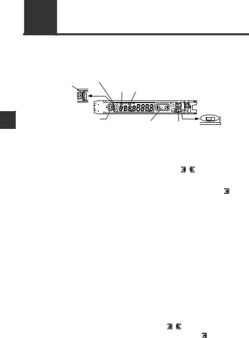
Sensor Amplifier
Display/control unit
 Expansion connector*1
Fiber lock lever |
Expansion connector*1*2 |
|
|
|
Dust cover |
|
|
|
Connection |
|
|
T |
Cable*3 |
|
|
R |
(FS-N1 |
/N1 |
P) |
Fiber transmit / receive indicators
Fiber connection ports
M8 connector type (FS-N1 CN/N1 CP)
e-CON connector (FS-N1 EN)
*1 Expansion protective cover is installed at the factory prior to shipment. *2 Not provided on the main unit (FS-N11 □ /N13 □ ).
*3 No connecting cables are provided for the Zero Line type (FS-N10).
1
Using Before
- Digital Fiber Sensor FS-N10 Series User's Manual - |
1-3 |
1
Using Before
1-2 Part Names
Display/control unit
1-output type (FS-N11/N12/N11C/N12C/N11EN/N12EN/N11MN/N10)
|
-2 |
|
|
|
|
|
|
|
|
-1 |
|
|
|
|
|
|
|
|
|
|
|
|
|
|
||
|
|
|
|
|
|
-1 |
|
|
|
|
|
1 |
2 |
||||
|
|
|
|
|
|
|
||
|
|
|
|
|
|
|
|
-2 |
|
Item |
|
|
|
|
Description |
|
|
-1 |
Operation indicator |
Indicates the current output (detection) status. |
|
|||||
|
(1-output/Zero line type) |
|
|
|
|
|
|
|
-2 |
Operation indicator |
Indicates the current output (detection) status of channels 1 and 2 |
||||||
|
(2-output type) |
separately. |
|
|
|
|
|
|
|
[SET] button |
Use when setting sensitivity, etc. |
|
|
||||
"Adjusting Sensitivity" (page 3-5) |
|
|||||||
|
|
|
||||||
|
Set value display |
Displays a setting value or advanced setting item in this area of 7- |
||||||
|
(green display) |
segment green indicators. |
|
|
|
|||
|
Current value display |
Displays the current value (received light intensity) and selection |
||||||
|
(red display) |
items for detailed settings with red 7-segment display. |
||||||
|
Manual button |
Used to adjust the setting value or select an option. |
||||||
|
|
Changing power modes. |
|
|
|
|||
|
Power select switch |
SEL: |
Allows you to set a power mode using the "Changing Power |
|||||
-1 |
|
Modes" function of basic setup. |
|
|||||
(1-output type)* |
|
|
||||||
M: |
Fixes the power mode to the "MEGA mode". |
|||||||
|
|
"Locking in MEGA Mode" (page 3-22) |
|
|||||
-2 |
Channel toggle switch |
Toggles between channels 1 and 2 for configuring the received light |
||||||
(2-output type)* |
intensity display or sensitivity setting. |
|
||||||
|
[PRESET] button |
Used for presetting or setting values or parameters. |
||||||
"Preset Function" (page 3-6) |
|
|
||||||
|
|
|
|
|||||
|
[MODE] button |
Used for toggling L-on/D-on, proceeding to advanced settings, or |
||||||
confirming selections. |
|
|
|
|
||||
|
|
|
|
|
|
|||
|
|
Lights when a DATUM mode is in effect. |
|
|||||
|
DTM indicator |
"DATUM1 mode" (page 4-9) |
|
|
||||
|
|
"DATUM2 mode" (page 4-11) |
|
|
||||
|
PST indicator |
Lights when preset value is set. |
|
|
||||
"Preset Function" (page 3-6) |
|
|
||||||
|
|
|
|
|||||
*Not provided on the Zero Line type (FS-N10).
1-4 |
- Digital Fiber Sensor FS-N10 Series User's Manual - |

1-3 Model Number Description
The numbers and letters used in product names are explained below:
FS-N1


(1) |
(2) |
(3) |
(4) |
|
|
(1) Amplifier type |
|
|
|
(2) Special type |
|
0: Expansion unit (Zero line) |
(None): Standard |
||||
1: Main unit (1-output) |
|
M |
: Monitor output |
||
2:Expansion unit (1-output)
3:Main unit (2-output)
4:Expansion unit (2-output)
(3) Cable type |
|
(4) Output type |
|
|||
(None): 2-meter cable |
N: NPN |
|
|
|||
C |
: M8 connector |
P: PNP |
|
|
||
E |
: e-CON connector |
|
|
|
|
|
|
|
|
|
|
|
|
|
Model |
(1) Amplifier type |
(2) Special type |
|
(3) Cable type |
(4) Output |
|
|
type |
||||
|
|
|
|
|
|
|
|
|
|
|
|
|
|
FS-N11N |
Main unit (1-output) |
|
|
|
NPN output |
|
|
|
|
|
|
|
|
FS-N11P |
Main unit (1-output) |
|
|
2-meter cable |
PNP output |
|
|
|
|
|
|
|
|
FS-N12N |
Expansion unit (1-output) |
|
|
NPN output |
||
|
|
|
||||
|
|
|
|
|
|
|
FS-N12P |
Expansion unit (1-output) |
|
|
|
PNP output |
|
|
|
|
|
|
|
|
FS-N11CN |
Main unit (1-output) |
Standard |
|
|
NPN output |
|
|
|
|
|
|
|
|
FS-N11CP |
Main unit (1-output) |
|
M8 connector |
PNP output |
||
|
|
|||||
|
|
|
|
|
|
|
FS-N12CN |
Expansion unit (1-output) |
|
|
NPN output |
||
|
|
|
||||
|
|
|
|
|
|
|
FS-N12CP |
Expansion unit (1-output) |
|
|
|
PNP output |
|
|
|
|
|
|
|
|
FS-N11EN |
Main unit (1-output) |
|
|
e-CON |
NPN output |
|
|
|
|
|
|
connector |
|
FS-N12EN |
Expansion unit (1-output) |
|
|
|||
|
|
|
||||
|
|
|
|
|
|
|
|
|
|
|
|
|
|
FS-N11MN |
Main unit (1-output) |
Monitor |
|
2-meter cable |
NPN output |
|
|
|
|
output |
|
|
|
|
|
|
|
|
|
|
|
|
|
|
|
|
|
|
|
|
|
|
|
|
FS-N13N |
Main unit (2-output) |
|
|
|
NPN output |
|
|
|
|
|
|
|
|
FS-N13P |
Main unit (2-output) |
|
|
2-meter cable |
PNP output |
|
|
|
|
|
|
|
|
FS-N14N |
Expansion unit (2-output) |
Standard |
|
NPN output |
||
|
|
|||||
|
|
|
|
|
|
|
FS-N14P |
Expansion unit (2-output) |
|
|
PNP output |
||
|
|
|
||||
|
|
|
|
|
|
|
FS-N13CP |
Main unit (2-output) |
|
|
M8 connector |
PNP output |
|
|
|
|
|
|
||
FS-N14CP |
Expansion unit (2-output) |
|
|
|||
|
|
|
|
|||
|
|
|
|
|
|
|
FS-N10 |
Expansion unit ( Zero line) |
|
|
|
|
|
|
|
|
|
|
|
|
1
Using Before
- Digital Fiber Sensor FS-N10 Series User's Manual - |
1-5 |
1-4 Fiber Units
The FS-N10 Series are amplifier units. They must be used in combination with separately-sold fiber units.
1 For fiber unit details, refer to the KEYENCE general catalog or contact your
Reference
nearest KEYENCE office.
UsingBefore |
Integrated |
Sleeve |
Bracket |
Threaded |
Cylinder |
bracket |
|
|
|
|
|
|
|
|
|
|
|
|
Narrow beam/ |
Retro-reflective |
Area |
Small spot |
Definite |
|
high power |
|
|
reflective |
reflective |
|
High-flex |
Oil/Chemical |
Liquid level |
LCD, |
|
|
|
resistant |
|
semiconductor |
|
1-6 |
- Digital Fiber Sensor FS-N10 Series User's Manual - |
|
|
|
|
Installation and Connection |
2 |
|
|
This chapter provides procedures for installing sensor amplifiers and |
|
||
|
|
||
cables, as well as operating precautions. |
|
|
|
|
|
|
|
2-1 |
Installing Sensor Amplifiers ................................ |
2-2 |
2-2 |
Connecting the Fiber Unit......................................... |
2-6 |
- Digital Fiber Sensor FS-N10 Series User's Manual - |
2-1 |
2
Connection and Installation
2-1 Installing Sensor Amplifiers
Mounting the Sensor Amplifier
Mounting on a DIN rail
1 |
Align the claw at the bottom of the main |
body with the DIN rail, as shown on the |
|
|
right. |
|
While pushing the main body in the direc- |
|
tion of the arrow (1), push down in the |
|
direction of arrow (2). |
2 |
To release the amplifier, raise the amplifier |
body in the direction of arrow (3) while |
pushing in the direction of arrow (1).
(3)
(2)
(1)
Installation on a wall

 Reference This method applies only when using the main unit independently. If the main unit is connected with an expansion unit(s), use the method of mount-
|
ing on a DIN rail. |
|
1 |
Mount the amplifier on the amplifier mount- |
|
ing bracket (OP-73880, sold separately), |
|
|
|
using the same manner as "Mounting on a |
|
|
DIN rail". |
|
2 |
Secure the unit with two M3 screws as |
|
shown in the illustration. |
OP-73880 |
Connecting multiple amplifiers
Up to 16 expansion units can be connected to 1 main unit. Note, however, that the 2-output type is considered as 2 expansion units.
Mount on DIN rail and install on metal surface when connecting  WARNING multiple amplifiers or mounting main units together.
2-2 |
- Digital Fiber Sensor FS-N10 Series User's Manual - |
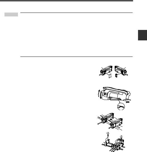
2-1 Installing Sensor Amplifiers
 Point • Contact your nearest KEYENCE office when connecting a unit other than the N-bus (KEYENCE’s wire-saving system) compatible sensor amplifier, including FS-N10 Series, or the NU Series communication module.
•Turn the power off before connecting multiple expansion units.
•Do not touch the expansion connector with your bare hands.
•When using the FS-N10 Series as a main unit, use the products within the expansion unit’s power voltage range if the power voltage range of the expansion unit is narrower than the FS-N10 Series.
1 |
Remove the protection covers from the main unit Main unit |
Expansion unit |
and expansion unit(s). |
|
|
2 |
Mount the main unit and expansion unit(s) on the |
|
(3) |
|
|
DIN rail. |
|
(2)
(1)
3 |
Slide the main unit and expansion unit(s) |
together. Engage the 2 claws of the expansion unit |
|
|
with the recesses on the main unit side until you |
|
hear/ feel a click. |
4 |
Attach the separately sold end units (OP-26751: a |
set of 2 units) to the DIN rail in the same manner |
|
|
as step (2) (Tightening torque: 0.6N•m or less). |
5 |
Secure the amplifiers between the end units. |
Tighten the screws at the top (2 screws × 2 units) |
with a Phillips screwdriver to fix the end units.


 End unit
End unit
2
Connection and Installation
- Digital Fiber Sensor FS-N10 Series User's Manual - |
2-3 |
2
Connection and Installation
2-1 Installing Sensor Amplifiers
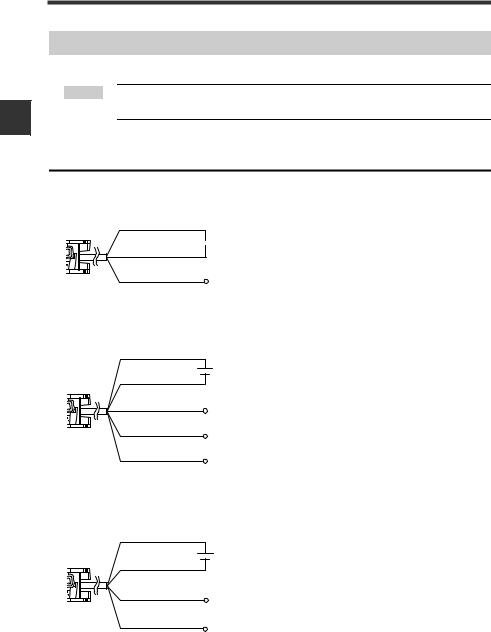
Wiring Diagrams for Sensor Amplifiers
 Point · Be sure to turn off the power before wiring.
· Insulate each input or output cable that will not be used.
Wiring Diagrams for Cable Types
1-output type (FS-N11/N12)
Brown*
 12 to 24 VDC
Blue*
Black |
Output |
|
*FS-N11N/N11P only
2-output type (FS-N13/N14)
Brown*
12 to 24 VDC
Blue*
Black
Output1
White
Output2
Pink
External input
*FS-N13N/N13P only
Monitor output type (FS-N11MN)
Brown
12 to 24 VDC
Blue
Black
 Output
Orange* |
Monitor output |
|
1 to 5V |
* Connect to a device having an input impedance 10 kΩ or more.
2-4 |
- Digital Fiber Sensor FS-N10 Series User's Manual - |
2-1 Installing Sensor Amplifiers
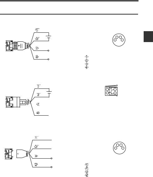
Wiring Diagrams for M8/e-CON Connector Types
M8 connector, 1-output type (FS-N11C/N12C)
Pins and wire colors of OP-73864/OP-73865
12 to 24 VDC
External input
Output
* FS-N11CN/N11CP only
|
|
2 |
4 |
M8 connector Pin layout |
1 |
3 |
|
|
|
|
|
Connected pin No. |
Wire color |
Function |
|
|
Brown |
12 to 24 VDC |
|
|
White |
External input |
|
|
Blue |
|
0V |
|
Black |
|
Output |
e-CON connector, 1-output type (FS-N11EN/N12EN)
e-CON connector Pin layout 1 |
2 |
12 to 24 VDC |
3 |
4 |
 External input
 Output
*FS-N11EN only
M8 connector, 2-output type (FS-N13CP/N14CP)
Pins and wire colors of OP-73864/OP-73865
|
|
|
|
|
|
|
|
|
|
|
|
|
|
|
|
|
|
|
|
12 to 24 VDC |
M8 connector Pin layout |
2 |
4 |
|
|
|
|
|
|
|
|
|
|
|
|
|
|
|
|
|
|
|
|
|
|||||
|
|
|
|
|
|
|
|
|
|
|
|
|
|
|
|
|
|
|
|
Output1 |
1 |
3 |
||
|
|
|
|
|
|
|
|
|
|
|
|
|
|
|
|
|
|
|
|
|||||
|
|
|
|
|
|
|
|
|
|
|
|
|
|
|
|
|
|
|
|
|
|
|
|
|
|
|
|
|
|
|
|
|
|
|
|
|
|
|
|
|
|
|
|
|
|
Connected pin No. |
Wire color |
Function |
|
|
|
|
|
|
|
|
|
|
|
|
|
|
|
|
|
|
|
|
|
Output2 |
|
Brown |
12 to 24 VDC |
|
|
|
|
|
|
|
|
|
|
|
|
|
|
|
|
|
|
|
|
|
|
White |
Output2 |
||
|
|
|
|
|
|
|
|
|
|
|
|
|
|
|
|
|
|
|
|
|
|
|||
|
|
|
|
|
|
|
|
|
|
|
|
|
|
|
*FS-N13CP only |
|
Blue |
|
0V |
|||||
|
|
|
|
|
|
|
|
|
|
|
|
|
|
|
|
|
|
|
|
|
|
Black |
Output1 |
|
2
Connection and Installation
- Digital Fiber Sensor FS-N10 Series User's Manual - |
2-5 |
2
Connection and Installation
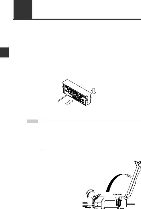
2-2 Connecting the Fiber Unit
This section provides procedures for connecting the fiber unit and operating precautions.
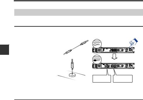
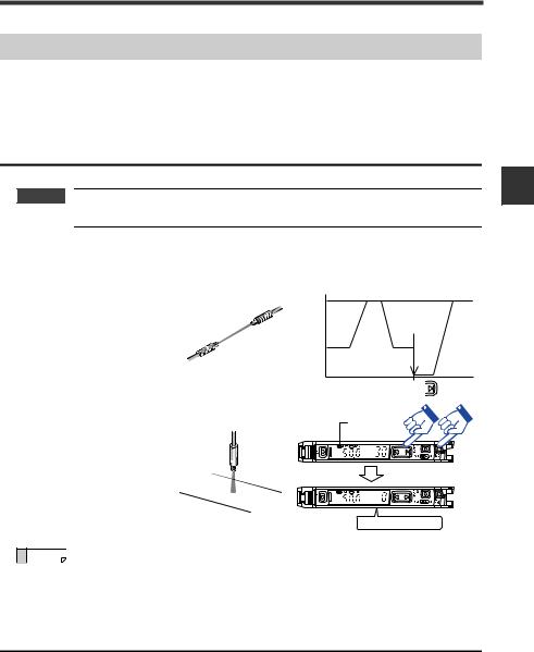
1 Install the fiber unit.
After the installation, check that the transmitter and receiver of the sensor are spaced properly. Also check that the optical axis is aligned.
2 If the fiber unit is a free cut type, cut any excess length of the fiber.
(1)Insert the fiber into the hole in the cutter.
(2)Bring down the blade in a single, swift motion to cut the fiber.
|
(2) |
Fiber |
Fiber cutter |
|
|
|
(OP-87098) |
|
(1) |
Always insert fiber from the side with writing.
 Point Failure to observe the cautions below may result in an improperly cut surface, which may reduce the detection distance.
·When cutting the fiber unit, be sure to use a gray fiber cutter (OP-87098)
·Cut the fiber unit in a single motion without stopping the blade halfway through.
·Do not use the same hole twice.
3 |
Open the dust cover in the |
|
direction of arrow (1). |
|
|
4 |
Move the fiber lock lever down in |
(1) |
the direction of arrow (2). |
(3) |
(2) |
2-6 |
- Digital Fiber Sensor FS-N10 Series User's Manual - |
2-2 Connecting the Fiber Unit
5 Insert the fiber unit into the fiber connection ports on the amplifier.
Insert the fiber unit until it reaches the position of the transmit / receive indicators (approximately 14 mm).
Fiber |
|
Fiber connection ports |
Fiber transmit / receive indicators |
6 Movefiber. the fiber lock lever back in the direction of arrow (3) to secure the
 Point · If a thin fiber unit is used, an adapter provided with the thin fiber unit will be required.
Make sure to use the adapter that matches the thin fiber unit.
Cable outer dia |
Adapter |
Appearance |
1.3 |
AdapterA |
|
(OP-26500) |
|
|
|
|
|
1.0 |
AdapterB |
|
(OP-26501) |
|
|
|
|
·To connect a coaxial reflective fiber unit to the amplifier, connect the single-core fiber to the transmitter (T) side, and connect the multiple-core fiber to the receiver side (R).
Single-core fiber |
Transmitter |
|
T |
|
R |
Multi-core fiber |
Receiver |
|
Position of fiber transmit / receive indicators
2
Connection and Installation
- Digital Fiber Sensor FS-N10 Series User's Manual - |
2-7 |

2-2 Connecting the Fiber Unit
MEMO
2
Connection and Installation
2-8 |
- Digital Fiber Sensor FS-N10 Series User's Manual - |
|
|
|
|
Basic Operation |
3 |
|
|
This chapter explains basic instructions for operating and setting the |
|
||
|
|
||
sensor amplifier. |
|
|
|
|
|
|
|
3-1 |
Quick Reference................................................. |
3-2 |
3-2 |
Switching Output ................................................ |
3-4 |
3-3 |
Adjusting Sensitivity ........................................... |
3-5 |
3-4 |
Setting the Current Received Light Intensity |
|
|
to 0 (Zero Shift) ................................................ |
3-16 |
3-5 |
Light emission/Received light intensity |
|
|
adjustment (Saturation Canceling) ................... |
3-18 |
3-6 |
Loading the Recommended Settings |
|
|
(Recipe Function) ............................................. |
3-19 |
3-7 |
Initialization....................................................... |
3-21 |
3-8 |
Locking in MEGA Mode.................................... |
3-22 |
3-9 |
Disabling the Key Operation............................. |
3-23 |
- Digital Fiber Sensor FS-N10 Series User's Manual - |
3-1 |
3
Operation Basic
3-1 Quick Reference
The main setting operations are explained according to purpose. Refer to Chapter 4 for information on advanced function settings and explanations not given below.
Operation |
Operation indicator |
|
|
|
|
|
|
|
|
|
|
|
|
|
|
|
||||||||
indicator |
(1-output/Zero line type) |
|
|
|
|
|
|
|
|
|
|
|
|
|
|
|
||||||||
(2-output type) |
|
|
|
|
|
|
PST |
DTM |
|
|
[MODE] |
|
|
|
|
|
||||||||
|
|
|
|
|
|
|
|
|
|
|
|
|
|
|
||||||||||
|
|
|
|
|
|
|
|
indicator |
indicator |
|
|
button [PRESET] |
|
|
||||||||||
|
|
|
|
|
|
|
|
|
|
|
|
|
|
button |
1 |
|
|
2 |
|
|||||
|
|
|
|
|
|
|
|
|
|
|
|
|
|
|
|
|
|
|
|
|
|
|||
|
|
|
|
|
|
|
|
|
|
|
|
|
|
|
|
|
|
|
|
|
|
|||
|
|
|
|
|
|
|
|
|
|
|
|
|
|
|
|
|
|
|
|
|
|
|||
|
|
[SET] button |
Manual button |
Power select switch |
|
|
|
|||||||||||||||||
|
|
|
|
|
||||||||||||||||||||
|
|
|
|
|
|
|
|
|
|
|
|
|
|
|||||||||||
|
|
|
|
|
|
|
|
|
|
|
|
|
|
|||||||||||
|
|
|
|
|
|
|
|
|
|
|
|
|
|
|
|
|||||||||
|
|
|
|
|
|
|
|
|
|
|
(1-output type)) |
|
|
|
|
|
||||||||
|
|
|
|
|
|
|
|
|
|
|
|
|
|
|
Channel select |
|
||||||||
|
|
|
|
|
|
|
|
|
|
|
|
|
|
|
switch (2-output type) |
|
||||||||
|
|
|
|
|
|
|
|
|
|
|
|
|
|
|
|
|
|
|
|
|
|
|
|
|
Purpose |
|
|
|
Description |
|
|
|
Operation procedures |
|
Reference |
||||||||||||||
|
|
|
|
|
|
|
page |
|||||||||||||||||
|
|
|
|
|
|
|
|
|
|
|
|
|
|
|
|
|
|
|
|
|
|
|
||
|
|
|
|
|
|
|
|
|
|
|
|
|
|
|
|
|
|
|
|
|
|
|||
Swiching the |
1 |
Swiching the output. (L-on/D-on) |
1. Press the [MODE] button. |
|
|
|
|
3-4 |
||||||||||||||||
|
|
|
|
|
|
|
|
|
|
|
|
|
||||||||||||
output |
2. Switch with the |
|
( ) button. |
|
||||||||||||||||||||
|
|
|
|
|
|
|
|
|
|
|
|
|||||||||||||
|
|
|
|
|
|
|
|
|
|
|
|
|
|
|
|
|
|
|
||||||
|
2 |
Set the current received light intensity |
Press the [PRESET] button while the PST |
3-6 |
||||||||||||||||||||
|
to "100.0". (Preset) |
|
indicator is OFF. |
|
|
|
|
|
|
|
|
|
||||||||||||
|
|
|
|
|
|
|
|
|
|
|
|
|
||||||||||||
|
|
|
|
|
|
|
|
|
|
|
|
|
|
|
|
|
|
|
|
|
|
|
||
|
|
When preset is valid, register the |
After step 7, press the [PRESET] button + |
|
||||||||||||||||||||
|
3 |
received light intensity ".0". |
|
3-7 |
||||||||||||||||||||
Adjusting the |
|
(Work-preset)* |
|
button in the state to be set as ".0". |
|
|
||||||||||||||||||
|
|
|
|
|
|
|
|
|
|
|
|
|
|
|
|
|
|
|
|
|
|
|
||
sensitivity and |
|
Set the received light intensity slightly |
While the PST indicator is OFF, press and hold |
|
||||||||||||||||||||
integrating the |
4 |
higher than when the setting was |
the [PRESET] button. Reflective model: When |
3-8 |
||||||||||||||||||||
display to "100.0" |
made, to "100.0". (Maximum sensitivity |
no workpiece is present. Thrubeam/Retro- |
||||||||||||||||||||||
|
|
|||||||||||||||||||||||
and ".0" |
|
preset)* |
|
reflective model: When a workpiece is present. |
|
|||||||||||||||||||
|
|
|
|
|
|
|
|
|
|
|
|
|
|
|
|
|
|
|
|
|
|
|
||
|
|
Automatically register "100.0" and ".0" |
Press and hold the [PRESET] button while the |
|
||||||||||||||||||||
|
5 |
when workpiece passes by. (Full Auto |
3-9 |
|||||||||||||||||||||
|
PST indicator is OFF. |
|
|
|
|
|||||||||||||||||||
|
|
preset)* |
|
|
|
|
|
|
||||||||||||||||
|
|
|
|
|
|
|
|
|
|
|
|
|
|
|
|
|
||||||||
|
|
|
|
|
|
|
|
|
|
|
|
|
|
|
|
|
|
|
|
|||||
|
6 |
Cancel the various preset functions. |
Press and hold the [PRESET] button. |
|
3-6 |
|||||||||||||||||||
|
|
|
|
|
|
|
|
|
|
|
|
|
|
|
|
|
|
|
||||||
|
|
Set the setting value at the midpoint |
1. Press the [SET] button once when a work- |
|
||||||||||||||||||||
|
7 |
between the received light intensity |
piece is present. |
|
|
|
|
|
|
|
|
|
3-11 |
|||||||||||
|
values when a workpiece is present |
2. Press the [SET] button once when no work- |
||||||||||||||||||||||
|
|
|
||||||||||||||||||||||
|
|
and absent. (2-point calibration) |
piece is present. |
|
|
|
|
|
|
|
|
|
|
|||||||||||
|
|
|
|
|
|
|
|
|
|
|
|
|
|
|
|
|
|
|
||||||
|
|
Set the setting value slightly higher |
Reflective model: Press and hold the [SET] but- |
|
||||||||||||||||||||
|
8 |
than the received light intensity value |
ton when no workpiece is present. Thrubeam/ |
3-12 |
||||||||||||||||||||
|
at which the setting was made. (Maxi- |
Retro-reflective model: Press and hold the |
||||||||||||||||||||||
|
|
|
||||||||||||||||||||||
Adjusting the |
|
mum sensitivity calibration) |
|
[SET] button when a workpiece is present. |
|
|||||||||||||||||||
|
|
|
|
|
|
|
|
|
|
|
|
|
|
|
|
|
|
|
|
|
|
|
||
|
Set the setting value automatically |
|
|
|
|
|
|
|
|
|
|
|
|
|
|
|||||||||
sensitivity |
|
Press and |
hold |
the [SET] |
button |
while the |
|
|||||||||||||||||
9 |
when a workpiece is passing through. |
3-13 |
||||||||||||||||||||||
|
workpiece passes through. |
|
|
|
|
|||||||||||||||||||
|
|
(Full auto calibration) |
|
|
|
|
|
|
||||||||||||||||
|
|
|
|
|
|
|
|
|
|
|
|
|
|
|
|
|
||||||||
|
|
|
|
|
|
|
|
|
|
|
|
|
|
|
|
|
|
|
|
|||||
|
|
Set the setting value to the base point |
1. Press the [SET] button once when no work- |
|
||||||||||||||||||||
|
|
piece is present. |
|
|
|
|
|
|
|
|
|
|
||||||||||||
|
10 |
where the workpiece is positioned. |
|
|
|
|
|
|
|
|
|
3-14 |
||||||||||||
|
2. Press and hold the [SET] button at the posi- |
|||||||||||||||||||||||
|
|
(Positioning calibration) |
|
|
||||||||||||||||||||
|
|
|
tioning point. |
|
|
|
|
|
|
|
|
|
|
|||||||||||
|
|
|
|
|
|
|
|
|
|
|
|
|
|
|
|
|
|
|
|
|||||
|
|
|
|
|
|
|
|
|
|
|
|
|
|
|
|
|
|
|
|
|
|
|
||
|
11 |
Finely adjust the setting value directly. |
Press the |
( |
|
) button. |
|
|
|
|
1-4 |
|||||||||||||
|
|
|
|
|
|
|
|
|
|
|
|
|
|
|
|
|
|
|
|
|||||
Shifting the |
12 |
Set the current display to "0". (Zero |
Press the [PRESET] button + |
|
button when |
3-16 |
||||||||||||||||||
received light |
shift) |
|
the PST indicator is OFF. |
|
|
|
|
|||||||||||||||||
|
|
|
|
|
|
|
||||||||||||||||||
intensity to "0" |
|
|
|
|
|
|
|
|
|
|
|
|
|
|
|
|
|
|
|
|
|
|
|
|
13 |
Cancel the zero shift function. |
Press and hold the [PRESET] button. |
|
3-16 |
||||||||||||||||||||
|
|
|||||||||||||||||||||||
|
|
|
|
|
|
|
|
|
|
|
|
|
|
|
|
|
|
|
|
|
|
|
|
|
Need to prevent |
|
|
|
|
|
|
|
|
|
|
|
|
|
|
|
|
|
|
|
|
|
|
|
|
the received light |
|
Automatically adjusts to appropriate |
Briefly press [MODE] + [SET] buttons with the |
|
||||||||||||||||||||
intensity from |
14 |
light emission and light receiving sen- |
amount of received light in maximum-saturated |
3-18 |
||||||||||||||||||||
becoming satu- |
|
sitivity. |
|
condition. |
|
|
|
|
|
|
|
|
|
|
|
|
||||||||
rated. |
|
|
|
|
|
|
|
|
|
|
|
|
|
|
|
|
|
|
|
|
|
|
|
|
|
|
|
|
|
|
|
|
|
|
|
|
|
|
|
|
|
|
|
|
|
|
|
|
|
3-2 |
- Digital Fiber Sensor FS-N10 Series User's Manual - |

|
|
|
|
|
|
|
|
3-1 |
|
Quick Reference |
||||
|
|
|
|
|
|
|
|
|
|
|
|
|
|
|
|
|
|
|
|
|
|
|
|
|
|
|
|
|
|
|
Purpose |
|
Description |
|
Operation procedures |
|
|
Reference |
||||||
|
|
|
|
|
page |
|||||||||
|
|
|
|
|
|
|
|
|
|
|
|
|
|
|
|
|
|
|
|
|
|
|
|||||||
|
|
|
|
1. Press and hold the [SET] button and [PRE- |
|
|||||||||
|
|
|
|
SET] button. |
|
|
|
|
|
|
|
|
|
|
|
Loading the |
|
Load the recommended settings. |
2. |
Display the LoAd screen with the |
( |
) |
|
||||||
|
recommended set- |
15 |
button, and press the [MODE] button. |
|
|
3-19 |
||||||||
|
(Recipe function) |
|
|
|||||||||||
|
tings |
|
3. Select the recipe such as r-1 |
FALL with the |
|
|||||||||
|
|
|
|
|||||||||||
|
|
|
|
|
( ) button. |
|
|
|
|
|
|
|
|
|
|
|
|
|
4. |
Press the [MODE] button to execute. |
|
|
|||||||
|
|
|
|
|
|
|
|
|
|
|||||
|
|
|
|
1. |
Press and hold the [SET] button and [PRE- |
|
|
|||||||
|
|
|
|
SET] button. |
|
|
|
|
|
|
|
|
|
|
|
Initializing the set- |
16 |
Initializing (Restore to factory default |
2. |
Press the [MODE] button while on the rSt |
|
3-21 |
|||||||
|
screen. |
|
|
|
|
|
|
|
|
|||||
|
tings |
settings) |
|
|
|
|
|
|
|
|
||||
|
|
3. |
Select init with the |
( |
) button. |
|
|
|||||||
|
|
|
|
|
|
|||||||||
|
|
|
|
4. |
Press the [MODE] button to execute. |
|
|
|||||||
|
|
|
|
|
|
|
|
|
|
|
|
|
|
|
|
Displaying the out- |
|
|
Set the channel switch to |
|
|
|
. |
|
|
|
|||
|
put 2 display |
17 Switch to the output 2 display screen. |
|
|
|
|
|
4-35 |
||||||
|
* The output 2 sensitivity and advanced set- |
|
||||||||||||
|
screen with the |
|
||||||||||||
|
|
|
tings can be modified in this state. |
|
|
|
||||||||
|
2-output type |
|
|
|
|
|
||||||||
|
|
|
|
|
|
|
|
|
|
|
|
|
|
|
|
|
|
|
|
|
|
|
|
|
|
|
|
|
|
|
Switching to the |
|
|
|
|
|
|
|
|
|
|
|
|
|
|
maximum received |
18 |
Adjust the power mode to the MEGA |
Set the power select switch to |
|
|
|
. |
|
3-22 |
||||
|
light intensity |
mode. |
|
|
|
|
||||||||
|
|
|
|
|
|
|
|
|
|
|
|
|
||
|
power mode |
|
|
|
|
|
|
|
|
|
|
|
|
|
|
|
|
|
|
|
|
|
|
||||||
|
|
19 Activating the key lock |
Press and hold the [MODE] button and the |
|
3-23 |
|||||||||
|
|
( |
) button simultaneously. |
|
|
|
|
|
||||||
|
|
|
|
|
|
|
|
|
|
|||||
|
|
|
|
|
|
|
|
|
||||||
|
|
20 Deactivating the key lock |
Press and hold the [MODE] button and the |
|
3-23 |
|||||||||
|
|
( |
) button simultaneously. |
|
|
|
|
|
||||||
|
|
|
|
|
|
|
|
|
|
|||||
|
|
|
|
|
|
|
|
|
|
|
|
|||
|
Preventing |
|
|
1. |
Press the |
( |
) button10 times while |
|
|
|||||
|
incorrect |
21 |
Activating the password-protected key |
holding down the [MODE] button. |
|
|
|
3-24 |
||||||
|
operations |
lock |
2. Input the password with the |
|
|
( |
) button. |
|||||||
|
|
|
|
|
||||||||||
|
|
|
|
|
|
|
||||||||
|
|
|
|
3. |
Press the [MODE] button to execute. |
|
|
|||||||
|
|
|
|
|
|
|
|
|
|
|
|
|||
|
|
|
|
1. |
Press the |
( |
) button 10 times while |
|
|
|||||
|
|
22 |
Deactivating the password-protected |
holding down the [MODE] button. |
|
|
|
3-24 |
||||||
|
|
2. Input the password with the |
|
|
( |
) button. |
||||||||
|
|
key lock |
|
|
||||||||||
|
|
|
|
|
|
|||||||||
|
|
|
|
3. |
Press the [MODE] button to deactivate the |
|
|
|||||||
|
|
|
|
key lock. |
|
|
|
|
|
|
|
|
|
|
|
|
|
|
|
|
|
|
|||||||
|
|
23 Setting the advanced functions |
Press and hold the [MODE] button. |
|
|
4-1 |
||||||||
|
|
|
|
|
|
|
|
|
|
|||||
|
|
|
Setting to rescale at each preset exe- |
1. |
Press and hold the [MODE] button, |
but- |
|
|
||||||
|
|
|
ton and [SET] button simultaneously. |
|
|
|
||||||||
|
|
24 cution so that analog output is "5 V" |
2. |
Press the [MODE] button once or twice. |
|
4-22 |
||||||||
|
Others |
|
output in respect to "100.0".* |
3. Select "Pr-A PrST" with |
|
( |
|
) button, and |
|
|||||
|
|
|
press the [MODE] button. |
|
|
|
|
|
|
|
||||
|
(Advanced |
|
|
|
|
|
|
|
|
|
||||
|
|
|
|
|
|
|
|
|
|
|
|
|
|
|
|
function settings, |
|
Switching the display to extended dis- |
After setting the sub-display with the advanced |
|
|||||||||
|
etc.) |
25 play or received light intensity hold |
function settings, press the [MODE] button |
|
4-23 |
|||||||||
|
|
|
display, etc. (sub-display) |
twice. |
|
|
|
|
|
|
|
|
|
|
|
|
|
|
|
|
|
|
|
|
|
|
|
|
|
|
|
|
Resetting the following values |
|
|
|
|
|
|
|
|
|
|
|
|
|
|
* Received light intensity hold value |
Press and hold the [MODE] button and [SET] |
|
4-25 |
||||||||
|
|
26 * Excess gain hold value |
|
|
||||||||||
|
|
button. |
|
|
|
|
|
|
|
|
|
|||
|
|
|
* Output when output 2 is in limit set- |
|
|
|
|
|
|
|
|
4-36 |
||
|
|
|
|
|
|
|
|
|
|
|
|
|
||
|
|
|
ting detection mode |
|
|
|
|
|
|
|
|
|
|
|
|
|
|
|
|
|
|
|
|
|
|||||
|
|
|
|
1. |
Press and hold the [SET] button and [PRE- |
|
|
|||||||
|
|
|
|
SET] button. |
|
|
|
|
|
|
|
|
|
|
|
|
27 Saving the settings (custom save) |
2. |
Display the SAvE screen with the |
( ) |
|
4-39 |
|||||||
|
|
button, and press the [MODE] button. |
|
|
||||||||||
|
|
|
|
|
|
|
||||||||
|
Saving and |
|
|
3. |
Select yES with the |
( |
) button. |
|
|
|
||||
|
loading the |
|
|
4. |
Press the [MODE] button to execute. |
|
|
|||||||
|
settings |
|
|
|
|
|
|
|
|
|
|
|
|
|
|
|
|
1. |
Press and hold the [SET] button and [PRE- |
|
|
||||||||
|
|
|
|
|
|
|||||||||
|
|
|
|
SET] button. |
|
|
|
|
|
|
|
|
|
|
|
|
28 Loading the settings (user reset) |
2. |
Press the [MODE] button on the rSt screen. |
4-40 |
|||||||||
|
|
3. |
Select USEr with the |
( |
) button. |
|
||||||||
|
|
|
|
|
|
|||||||||
4.Press the [MODE] button to execute.
*Not available for the FS-N10 Series shipped before March 10, 2011.
3
Operation Basic
- Digital Fiber Sensor FS-N10 Series User's Manual - |
3-3 |
3
Operation Basic
3-2 Switching Output
Output Switch (L-on/D-on)
This function configures when the output turns ON.
1 |
When the current received light inten- |
|
sity is displayed, press the [MODE] but- |
||
|
ton. |
|
|
The current output condition (L-on or D- |
|
|
on) is displayed.*1 |
|
2 |
Press the |
button to switch the out- |
put condition, and then press the |
||
[MODE] button.
Select "D-on" if you want to output the ON signal when the beam is blocked (a work-
piece is present.) for a thrubeam or retro-reflective model.
Select "L-on" if you want to output the ON signal when the beam is received (a workpiece is present.) for the reflective model.
The output condition is switched, and the current received light intensity is displayed.*2
*1 If you do nothing for 3 seconds or more or press the [MODE] button, the received light intensity display is automatically restored.
*2 When using the sub-display, the screen will switch between the current received light intensity L-on/D-on screen sub-display current received light intensity and so forth each time the [MODE] button is pressed.
 "Sub Display" (page 4-23)
 Point • Area detect mode, rising edge detect mode, and falling edge detect mode are selectable by n.o./n.c.
"Area detection mode" (page 4-14) "Edge detection mode" (page 4-16)
•When using a 2-output type, output can be individually selected with channel 1/2.
3-4 |
- Digital Fiber Sensor FS-N10 Series User's Manual - |

3-3 Adjusting Sensitivity
This manual refers to the values that select ON/OFF output of the sensor amplifiers as "Set values." In addition, the manual refers to the adjustment of set values as "Adjusting Sensitivity." This section describes the sensitivity adjusting method.
List of Sensitivity Adjusting Methods
Sensitivity adjusting method for the FS-N10 Series is broadly divided into two categories:
Preset
Simple operation allows sensitivity adjustment concurrently with correction of the received light intensity to "100.0" or "0.0"
This function helps preventive maintenance by eliminating dispersion of the received light intensity due to the contents of detection or individual workpieces.
However, this is not suitable for detection of transparent workpiece because there is a small difference in the received light intensity between presence and absence of a workpiece.
Calibration
Sensitivity can be adjusted by a simple operation. This function does not correct the received light intensity.
This function is applied for using the received light intensity without correction or for high-precision detection.
Calibration is also available in a preset state.
How to select sensitivity adjusting method
Sensitivity |
|
|
|
|
|
adjusting |
|
Status of use |
Functions |
Contents |
Reference |
method |
|
|
|
|
|
|
|
|
|
|
|
|
|
Using thrubeam/retro-reflective |
|
When there is no workpiece, by sim- |
|
|
|
Preset |
ply pressing the PRESET button, |
3-6 |
|
|
|
models |
|||
|
|
|
sensitivity adjustment is completed. |
|
|
|
Basics |
|
|
|
|
|
|
|
|
|
|
|
|
Preset to maxi- |
When there is no workpiece, by sim- |
|
|
|
|
|
|
||
|
|
Using reflective model |
ply holding the PRESET button, |
3-8 |
|
|
|
mum sensitivity |
|||
|
|
|
sensitivity adjustment is completed. |
|
|
Preset |
|
|
|
|
|
|
|
|
|
|
|
|
Not successfully displaying the |
|
|
|
|
|
|
|
|
|
|
|
|
intensity level as "100.0" and |
Work preset |
The status in which "100.0" or ".0" is |
3-7 |
|
At times |
".0" depending on the presence |
displayed can be set at your choice |
||
|
|
|
|||
|
like this |
of a workpiece. |
|
|
|
|
|
Mobile object moves fast |
Full automatic |
Preset is enabled by using a fast- |
3-9 |
|
|
preset |
moving workpiece. |
||
|
|
|
|
||
|
|
|
|
|
|
|
|
|
|
The setting can be established just |
|
|
Basic |
Using thrubeam/retro-reflective |
Two-point |
by pressing the [SET] button once |
3-11 |
|
models |
calibration |
when a workpiece is present and |
||
|
|
|
|||
|
|
|
|
absent. |
|
|
|
|
|
|
|
|
|
Mobile body moves fast |
Full automatic |
Calibration is enabled by using a |
3-13 |
|
|
calibration |
fast-moving workpiece. |
||
|
|
|
|
||
Calibration |
|
|
|
|
|
|
Using the unit in the environ- |
Maximum sensi- |
The setting seldom causes malfunc- |
|
|
|
|
ment that tends to get dirty |
tion even in the environment that |
3-12 |
|
|
At times |
tivity calibration |
|||
|
easily. |
tends to get dirty easily. |
|
||
|
like this |
|
|
||
|
|
|
|
|
|
|
|
Using the unit for positioning |
Positioning cali- |
The setting suitable for positioning is |
3-14 |
|
|
bration |
available. |
||
|
|
|
|
||
|
|
|
|
|
|
|
|
Using the unit for high-preci- |
Percentage cali- |
Effective for making correction from |
3-15 |
|
|
sion detection |
bration |
external devices such as PLC. |
|
|
|
|
|||
|
|
|
|
|
|
3
Operation Basic
- Digital Fiber Sensor FS-N10 Series User's Manual - |
3-5 |
3
Operation Basic
3-3 Adjusting Sensitivity
Preset Function
Enabling the preset function
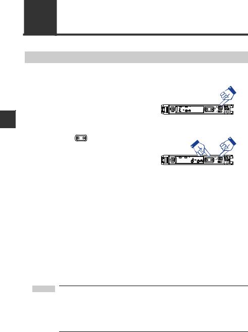
When the PST indicator is not lit, press the [PRESET] button.
The PST indicator lights
in green. The current value is set to "100.0"
and the setting value is set to "50.0".
 Green PST lights up

 Workpiece
Setting value |
Current value is |
is "50.0" |
"100.0" |
Disabling the preset function
When the PST indicator is lit, press and hold the [PRESET] button.
•The PST indicator turns off, indicating that the preset function has been disabled.
•Once the preset function is disabled, the setting value is recalculated while retaining the ratio of the setting value and received light intensity.
3-6 |
- Digital Fiber Sensor FS-N10 Series User's Manual - |
3-3 Adjusting Sensitivity
Work-Preset Function
This function calibrates the current value to ".0". After the preset function has been executed with "100.0" displayed, and then executing this function with ".0" displayed, 2 random set points can be calibrated to "100.0" and ".0".
* Not available for the FS-N10 Series shipped before March 10, 2011.
Enabling the work-preset function

 Impotant The work-preset function can be used with the preset function (when preset is enabled).
While the preset function is enabled, press the [PRESET] button and  button simultaneously.
The received light intensity
at that point is set to ".0". The value set to "100.0" using
the preset function does not change.
100.0 |
3.0 |
.0 |
PRESET + |
Green "PST" lights up
3
Operation Basic
Current value is ".0"
Reference Even if the received light intensity is low during preset and is high during work-preset, the value is set to "100.0" during preset and ".0" during work-
preset. When the actual received light intensity increases, the display will
approach ".0". (The preset saturation level is decreased with respect to "100.0".)
Disabling the work-preset function
When the PST indicator is lit, press and hold the [PRESET] button.
•The PST indicator turns off, indicating that the work-preset function has been disabled.
- Digital Fiber Sensor FS-N10 Series User's Manual - |
3-7 |
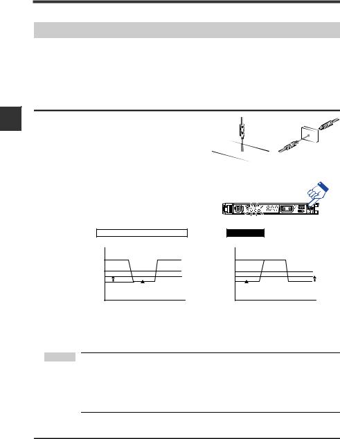
3
Operation Basic
3-3 Adjusting Sensitivity
Maximum Sensitivity Preset Function
This function calibrates the reference state to ".0" and the state at which the received light intensity is slightly higher as "100.0".
This function is useful with the reflective model to detect while using the background as a reference.
* Not available for the FS-N10 Series shipped before March 10, 2011.
Enabling the maximum sensitivity preset function
When no workpiece is present for the |
Workpiece |
|
1 reflective model, or when a workpiece |
||
|
||
is present for thrubeam model/retro- |
|
|
reflective model, press and hold the |
|
|
[PRESET] button for 3 seconds or more |
|
|
while the PST indicator is OFF. |
|
|
Release the button when "Auto" flashes. |
|
|
Calibration is complete after the setting |
|
|
value flashes momentarily, and then stops |
|
|
(lights up). |
|
|
The PST indicator lights in green, and the |
|
|
setting value is set to "50.0". |
|
|
Thrubeam Model/Retro-reflective Model |
Reflective Model |
|
Received light intensity |
|
|
No workpiece |
|
"100.0" |
Saturation point |
|
"50.0" |
Setting value |
|
".0" |
With workpiece |
1 |
|
|
|
Received light intensity |
|
|
With workpiece* |
|
|
Saturation point |
|
"100.0" |
Setting value |
|
"50.0" |
No workpiece* |
1 |
".0" |
|
|
|
*Where detection occurs on a target having a background, the maximum sensitivity setting ignores the background. Maximum sensitivity setting is not available if the background is more reflective than the workpiece.
 Point • When the amount of the light received is in saturated state (at a value higher than at the time of extended display on page 4-30), maximum sensitivity preset function cannot be implemented.
("---- ----" is indicated when operating 1.)
 "Light emission/Received light intensity adjustment (Saturation Canceling)" (page 3-18)
Disabling the maximum sensitivity preset function
When the PST indicator is lit, press and hold the [PRESET] button.
•The PST indicator turns off, indicating that the maximum sensitivity preset function has been disabled.
3-8 |
- Digital Fiber Sensor FS-N10 Series User's Manual - |
Loading...