


Two-color Digital Display
Pressure Sensor
AP-30 Series
Instruction Manual
PART NAMES AND FUNCTIONS
AUTO key |
|
|
In auto-tuning mode, use |
|
|
this key to detect pres- |
|
|
sure. In measurement |
|
|
mode, press this key for 2 |
|
|
seconds or more to adjust |
A |
|
the zero-point. |
||
|
||
SET key |
|
|
Use this key to display or |
|
|
change preset values. |
|
Output indicator 1 (Red LED)
Output indicator 2 (Green LED)
Display unit label
Housing
UP/DOWN key
Use these keys to set output modes, or to change preset values or units.
Hexagonal socket bolt
Rear metal casing (Die-cast zinc)
■ Display unit label
The AP-30 series enables you to select the display units for pressure.
Attach the included display unit label for the desired units at the 

position in the figure.
SPECIFICATIONS
Type |
Negative |
|
Positive pressure |
|
|
Compound |
||
pressure |
|
|
|
pressure |
||||
|
|
|
|
|
|
|||
Model 1. |
AP-31(Z) |
|
AP-32(Z) |
AP-33(Z) |
|
|
AP-34(Z) |
|
|
0 to -101.3 kPa |
0 to 100.0 kPa |
0 to 1.000 MPa |
|
+101.3 to |
|||
|
|
–101.3 kPa |
||||||
Rated pressure |
(0 to -760 |
|
(0 to 1 |
(0 to 10 |
|
|
||
|
|
|
(+760 mmHg |
|||||
|
mmHg) |
|
kgf/cm2) |
kgf/cm2) |
|
|
||
|
|
|
|
to -760 mmHg) |
||||
|
|
|
|
|
|
|
||
Proof pressure |
490 kPa |
|
490 kPa |
1.47 MPa |
|
|
490 kPa |
|
(5 kgf/cm2) |
|
(5 kgf/cm2) |
(15 kgf/cm2) |
|
|
(5 kgf/cm2) |
||
|
|
|
|
|||||
Pressure type |
|
|
Gauge pressure |
|
|
|
||
Fluid types |
|
|
Air or noncorrosive gases |
|
|
|
||
Display |
3 1/2-digit, 2-color, 7-segment LED (Character height: 11 mm) |
|||||||
|
0.1 kPa, |
|
0.1 kPa, |
0.001 Mpa, |
|
|
0.2 kPa, |
|
Display resolution |
1 mmHg, |
|
0.001kgf/cm2, |
0.01kgf/cm2, |
|
|
2 mmHg, |
|
|
0.02 Psi |
|
0.02 Psi |
0.2 Psi |
|
|
0.04 Psi |
|
Detectable pressure range |
|
|
-15% to +110% of F.S. |
|
|
|
||
Repeatability |
|
|
± 0.2% of F.S. (5 ms or more) |
|
||||
Response time (chattering |
|
|
2.5/5/100/500 ms (selectable) |
|
||||
prevention function) |
|
|
|
|||||
|
|
|
|
|
|
|
||
Zero-shift input 2. |
Non-voltage input (contact, solid-state), |
|||||||
|
|
Input time: 20 ms or more |
|
|
|
|||
|
|
|
|
|
|
|||
Control output |
NPN open-collector: 100 mA max. (40 V max.), Residual |
|||||||
voltage: 1 V max. 2-output (N.O./N.C. selectable) |
||||||||
|
||||||||
Analog output 3. |
1 to 5 V (Load impedance: 47 kΩ |
min.) |
||||||
Temperature fluctuation |
± 2% max. (of F.S.) of detecting pressure at 25° C (0 to 50° C) |
|||||||
for analog output |
||||||||
|
|
|
|
|
|
|
||
Temperature fluctuation |
± 1% max. (of F.S.) of detecting pressure at 25° C (0 to 50° C) |
|||||||
for display |
||||||||
|
|
|
|
|
|
|
||
Current consumption |
|
50 mA (at 24 V), 90 mA (at 12 V) |
|
|||||
Power supply |
12 to 24 VDC± 10%, Ripple (p-p): 10% max. |
|||||||
Ambient temperature |
|
|
0 to 50° C |
|
|
|
||
Relative humidity |
|
|
35 to 85% |
|
|
|
||
Vibration |
10 to 55 Hz, 1.5 mm double amplitude in X, Y, |
|||||||
and Z directions, 2 hours respectively |
||||||||
|
||||||||
|
Front housing: Polyamide, Front panel sheet: PET, |
|||||||
Material |
Rear housing: Polysulfone, Pressure port: Die-cast zinc, |
|||||||
|
|
|
Cable: Oil-proof cabtyre cable |
|
||||
Weight |
|
|
Approx. 120 g |
|
|
|
||
(including 2 m cable) |
|
|
|
|
|
|||
|
|
|
|
|
|
|
||
1.The zero-shift type sensor is suffixed with Z after the model name.
2.Z type only. 3. Not provided with Z type
■ ACCESSORIES
• |
Instruction manual: 1 • |
Display unit |
Mounting |
Mounting |
|
• |
Hexagonal-socket |
|
label sheet: 1 |
bracket A: 1 |
bracket B: 1 |
|
|
|
|
||
|
port stopper: 1 |
• |
Quick reference |
|
|
|
|
|
sheet: 1 |
|
|
|
|
|
|
|
|
|
|
|
|
|
|
|
|
|
|
|
|
|
|
|
|
|
|
|
|
|
|
|
|
|
|
|
|
CONNECTIONS AND INPUT/OUTPUT CIRCUIT |
||||||||||||||||
■ Connections |
|
|||||||||||||||
• Drive current load |
|
|
|
|
|
|
|
|
|
|
|
Brown |
12 to 24 VDC |
|||
|
|
|
|
|
|
|
|
|
|
|
||||||
|
|
|
|
|
|
|
|
|
|
|
|
Black or white |
|
|||
|
|
|
|
|
|
|
|
|
|
|
|
|
|
|
|
|
|
|
|
|
|
|
|
|
|
|
|
|
|
Load |
|
||
|
|
|
|
|
|
|
|
|
|
|
|
Blue |
0 V |
|||
• Input to voltage input equipment |
||||||||||||||||
|
||||||||||||||||
|
|
|
|
|
|
|
|
|
|
|
|
Brown |
12 to 24 VDC |
|||
|
|
|
|
|
|
|
|
|
|
|
|
|||||
|
|
|
|
|
|
|
|
|
|
|
|
|
|
|
4.7 k Ω |
|
|
|
|
|
|
|
|
|
|
|
|
|
Black or white |
Voltage output |
|||
|
|
|
|
|
|
|
|
|
|
|
|
|
|
|
||
Blue |
0 V |
|
■ Input/output circuit
• |
Output circuit |
|
|
Brown |
Load |
Load |
|
circuit |
|
|
|
||
|
mainsensorPressure |
currentOver |
circuitprotection |
|
|
12 to 24 VDC |
|
Black |
|
|
|||
|
|
|
|
|
|
|
|
|
|
|
(Control output 1) |
|
|
|
|
|
|
White |
|
|
|
|
|
|
(Control output 2) |
||
|
|
|
|
Blue |
|
0 V |
|
|
|
|
|
|
|
AP-31Z/32Z/33Z/34Z (Z type only)
Input circuit (Zero-shift input) Zero-shift input resets the display to “0” at the rising edge of the signal.
12 to 24 VDC
Pressuresensor |
main circuit |
3.3 k Ω |
|
|
Pink |
||
11 k Ω |
Blue |
AP-31/32/33/34 (Except for Z type)
Analog output circuit
Pressure sensor |
Protection |
Pink |
Analog |
circuit |
|
output (+) |
|
|
|
||
main circuit |
Blue |
0 V |
|
|
|
PIPING/MOUNTING
• You can select from three |
Hexagonal socket bolt |
pressure port positions by |
|
selecting or replacing the |
|
pressure ports. Select the |
|
optimal position based on |
|
your location.
CAUTION |
* The arrow shows the pressure port |
|
positions that can be selected. |
||
|
The maximum tightening torque for the hexagonal socket bolt is 0.3 Nm (Approx. 3 kgf•cm). To avoid breakage, do not exceed the specified value.
•An Rc (PT) 1/8 internal thread is provided on the pressure port of the AP-30 series. Commercially available air-pressure pipe joints or nipples can be used.
•When connecting a joint or a plug,
use a wrench (14 mm) to hold the metallic part as shown in the figure to avoid a large force being applied to the sensor housing (resin part).
Hold this part with a wrench (14 mm).
•Be sure to block an unused pressure port with the hexagonal-socket port stopper provided.

 CAUTION
The maximum tightening torque for the hexagonal-socket port stopper is 10 Nm (Approx. 100 kgf•cm). To avoid breakage, do not exceed the specified value.
•To prevent air leaks, wrap the male screw with sealing tape.
•To mount the AP-30 series to a panel using the panel mounting holder set (OP-31357), use a panel with 1 to 3.5 mm thickness.
• Special mounting brackets are included with the AP-30 series. Use the type of mounting bracket
appropriate for the location where the sensor is mounted. To mount the sensor, remove the hexagonal socket bolts and then
retighten them through the
mounting bracket.
Hexagonal
socket bolts
CAUTION
The maximum tightening torque for the hexagonal socket bolt is 0.3 Nm (Approx. 3 kgf•cm). To avoid breakage, do not exceed the specified value.
SAFETY PRECAUTIONS
Be sure to follow the instructions below to avoid malfunctions.

 CAUTION
■ Connection
•When using a commercially available switching regulator, be sure to ground the frame ground terminals.
•Isolate the sensor’s wiring from power lines or high-voltage lines; otherwise, the sensor may malfunction due to noise interference.
■ Other
•Do not use the AP-30 series for the detection of corrosive gases or liquid.
•Do not insert any objects, such as wires, from the pressure port.
The pressure-sensing element may break, resulting in malfunctions.
•Do not press the front panel keys with a pointed object.
•The AP-30 series does not have an explosion-proof structure. Do not use it for the detection of flammable gases.
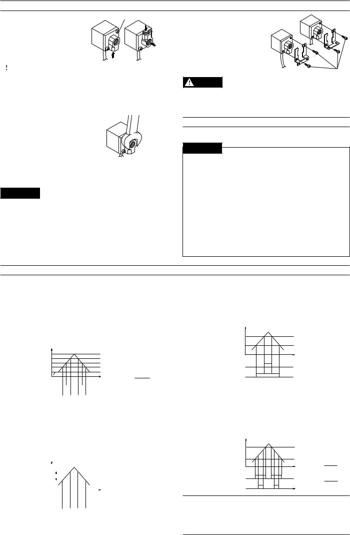
OPERATION MODE SELECTION
■ Auto-tuning mode (F-1)
Using the AUTO key, detect the upper limit value (A) and the lower limit value (b). The detection level (C) is automatically set at the midpoint between the two values. (You can finely adjust the preset value C within the range between A and b.)
Control output 1: The sensor turns on when the pressure exceeds the preset value C.
Control output 2: The sensor turns on when the pressure goes outside the stability levels.
Pressure |
* The stability levels are |
|
A |
automatically set as |
|
SH |
shown in the following |
|
Preset value C |
||
calculations. |
||
SL |
||
b |
SH = (A + C) |
|
0 |
Control output 1 ON |
2 |
|
||||||||
(OUT 1)OFF |
|
|
|
|
|
|
|
SL = |
(C + b) |
|
|
|
|
|
|
|
|
||||
Control output 2 ON |
|
|
|
|
|
|
|
|||
|
|
|
|
|
|
|
|
|
||
(OUT 2)OFF |
|
|
|
|
|
|
|
2 |
|
|
|
|
|
|
|
|
|
||||
■ Hysteresis mode (F-2)
Set desired detection level (H) and hysteresis (h) for the detection.
Control output 1: The sensor turns on when the pressure exceeds the preset value H. When the pressure falls by the preset value h, the sensor turns off.
Control output 2: The sensor turns on when the pressure goes outside the hysteresis width (H - h).
Pressure
Preset value H |
|
|
|
|
|
|
|
|
h: Hysteresis width of |
|
|
|
|
|
|
|
|
OUT1 |
|
|
h |
|
|||||||
H-h |
|
|
* When h is set to a |
||||||
|
|
|
|
|
|
|
|
|
value close to 0, if |
0 |
|
|
|
|
|
|
|
|
pressure fluctuates |
|
|
|
|
|
|
|
|||
Control output 1 ON |
|
|
|
|
|
around the detection |
|||
|
|
|
point, OUT1 will |
||||||
(OUT 1)OFF |
|
|
|
|
|
|
|
|
|
|
|
|
|
|
|
|
|||
Control output 2 ON |
|
chatter. |
|||||||
(OUT 2)OFF |
|
|
|
|
|
|
|
|
|
|
|
|
|
|
|
|
|
||
■ 2-independent mode (F-3)
Set two desired detection points (A and B).
Control output 1: The sensor turns on when the pressure exceeds the preset value A.
Control output 2: The sensor turns on when the pressure exceeds the preset value b.
Pressure
Preset value A
Preset value b
0
Control output 1 ON (OUT 1)OFF
Control output 2 ON (OUT 2)OFF
■ Window mode (F-4)
Set desired upper limit value (H) and lower limit value (L).
Control output 1: The sensor turns off when the pressure goes outside of the range between the upper limit value (H) and lower limit value (L).
Control output 2: The sensor turns off when the pressure goes outside of the stability levels.
Pressure
Preset value H SH
SL  Preset value L
0
Control output 1 ON (OUT 1)OFF
Control output 2 ON (OUT 2)OFF
*The stability levels are automatically set as shown in the following calculations.
SH = H – (H - L) 4
(H - L)
SL = L +
4
Note 1: The above description shows the operation of control outputs 1 and 2 when the output selector switch is set to N.O.
When the output selector switch is set to N.C., the operation of control outputs 1 and 2 is inverted.
Note 2: Except for OUT1 in hysteresis mode, each control output includes an internal hysteresis of 0.5% of F.S.
 Loading...