

Key Digital KD-MSWCAT8x8, KD-MSWCAT4x4, Fat Boy KD-MSWCAT8x8, Fat Boy KD-MSWCAT4x4 Addendum
Page 1

KD-MSWCAT8X8 KD-VACRX
KD-MSWCAT4X4 KD-CVARX
Addendum
This addendum describes additional features of Key Digital® FatBoy Series™
KD-MSWCAT8X8 and KD-MSWCAT4X4 spotlighting integration with KD-VACRX
and KD-CVARX Receiver Baluns.
KD-MSWCAT8x8
KD-MSWCAT4x4
Component/VGA with Audio via CAT5 Matrix Switchers
Page 2

Page 2
© 2010 Key Digital, Inc. All rights reserved.
The following new features have been added to both
the KD-MSWCAT8x8 and KD-MSWCAT4x4 products:
Key Features
» Allows the use of either KD-VACRX or KD-CVARX receive Baluns
» KD-CVARX can be used with a Digital or Analog Audio Input (Analog Output only)
» Can now route IR signals when in Component mode via unused “H” (Horizontal sync)
signal path
Key Benefits
» Can mix both KD-VACRX and KD-CVARX Baluns on single unit
» Control display or other local (room) components by sending IR through KD-VACRX and
KD-CVARX Baluns
» Allows use of KD-CVARX Baluns when Digital Audio and RS232 Output isn’t required
Additional Key Features
» Front panel LED input/output assignment confirmation
» Easily controlled via IR Remote (included) with discrete codes, Serial IR, and RS-232
» Slim 1U Rack chassis for space conservation
RS232 Commands:
The following new RS232 commands have been added to provide control for the new features:
½ ‘SPCVTx’ - Video Type command: where x = 0 or 1 (0 = Component, 1 = RGBHV)
» Note: default is component.
» This command determines whether unit will switch Component or RGBHV signals.
» Example: To switch the unit from Component to RGBHV mode, enter the command;
‘SPCVT1’
» (Please note that a system reboot is required after a ‘Video Type’ switch for the settings to
take effect)
½ ‘SPOxxSRyy’ – IR Switching command: where xx = Output number, yy = Input number.
» This command directs the IR path from your chosen input to your chosen output
independent of your A/V routing.
» Example: to direct the IR path from input 4 to output 2, issue the command: ‘SPO02SR04’
» NOTE: for expansion configurations, total number of inputs will be limited to 8
(or 4 for KD-MSWCAT4x4
» The default assignments for IR routing are Input 1 to Output 1, Input 2 to Output 2 etc.
½ ‘SP C C5T hh’ - CAT5 Output Type Mask: where hh = hex value for selecting which outputs will
have KD-VACRX Balun and which will have KD-CVARX Baluns (0-VAC, 1-CVA) ‘0’ is the default
setting
» This command tells the unit which type of Balun is connected to each output number. A
selected output will choose the KD-CVARX Balun; an unselected output chooses the KDVACRX Balun (default).
Page 3
Page 1
» See the hex value/binary number conversion table to generate the proper number to enter
for this value.(pg. 4)
» The status display through RS-232 has been updated to reflect the changes.
» Output:
» 01 : Video= 01, Audio= 01, IR= 01 : Active : Mute Interval= 00
Balun= VAC : V= 50 B= 20 L= 12 M= 12 T= 12 LP= 00
» 02 : Video= 02, Audio= 02, IR= 02 : Active : Mute Interval= 00
Balun= VAC : V= 50 B= 20 L= 12 M= 12 T= 12 LP= 00
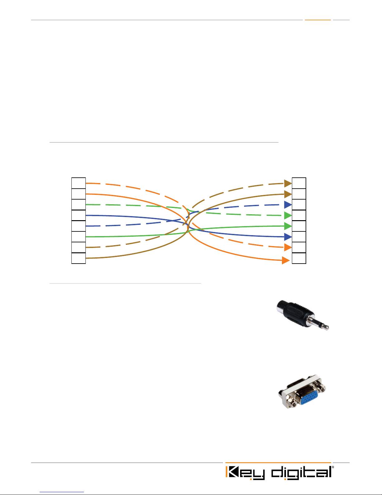
Pin out for using KD-CVARX Baluns with KD-MSWCAT8X8 / 4X4
Please note that to utilize the KD-CVARX Baluns you will need to terminate your CAT5 cabling
using the following pin out:
1 1
2 2
3 3
4 4
5 5
6 6
7 7
8 8
KD-MSWCAT8X8 / 4X4 KD-CVARX
IR routing through KD-MSWCAT8X8 / 4X4:
In order to send IR signals through the KD-MSWCAT8X8/4X4, you will need to follow the
configuration described below.
½ To input IR signals, you will need to convert your powered IR distributions
output to an RCA type connector. Typically you can use a mono 3.5mm jack
to RCA adapter (as shown).
½ Using a standard RCA male to male cable, connect this RCA to the unused ‘H’ or Horizontal
Sync input going into the switch. The supplied breakout cable is used for Component signals
and has 3 RCA connections. You will need a 5 RCA to VGA (Part number KD-VACBL not
included) breakout connector for both Switch and Balun. (Total of 2 per signal, see complete
parts list below).
½ NOTE: When using the KD-CVARX Baluns, you will need to supply a female
to female HD15 gender changer to connect the Balun to the breakout cable
(KD-VACBL) this changer is not needed for the KD-VACRX Baluns.
½ At the Balun side, plug an RCA to 3.5mm female mono jack adapter into the
unused ‘H’ or Horizontal output coming off the HD15 to 5 RCA breakout cable from the Balun.
You may plug your emitter directly into this adapter which can then be placed onto your display
or any other device you wish to control. You may repeat this for each IR signal you wish to route
through the KD-MSWCAT8X8/4X4.
Page 4

Page 2
Here is a complete list of all items required to send IR through the KD-MSWCAT8X8/4X4.
(Items listed are for a single connection).
Product Qty. Description Use
1
3.5mm male mono
jack to RCA female
adapter
Converts IR Distribution output to
RCA to connect to Baluns
2
KD-VACBL 5 RCA
breakout cable
Breaks out 15 pin to 5 separate
female RCA connections
1
Single male RCA to
male RCA
Carries IR signal to input of
breakout cable
1
RCA male to 3.5mm
mono female adapter
Converts IR output of Balun to
allow standard emitter to plug in
1
15 pin VGA female to
female adapter
If using KD-CVARX Baluns for 5
RCA breakout cable to fit
1
Standard IR emitter To send IR to device you wish to
control
Audio Connections
The KD-MSWCAT4x4 / 8x8 has Two (2) 3.5mm audio input connections for each video input. For
standard Analog Stereo sources, utilize the left input. For Digital PCM sources utilize the right input.
For Balanced Analog sources, utilize both inputs. Pin outs for these connections are shown below.
Page 5

Page 3
Standard Analog Stereo connections:
This is the standard unbalanced audio pin out. This signal will be available when using either KDVACRX or KD-CVARX Balun.
1 1
2 2
3 3
4 4
5 5
6 6
7 7
8 8
KD-MSWCAT8X8 / 4X4 KD-CVARX
Analog Audio
Balanced Audio
Left
Left
Right
Gnd
Gnd Left + Right+
Gnd Gnd
+ – + –
Tip
Ring
Sleeve
R
L
Digital Audio
Gnd
PCM
Gnd +
+
Gnd
R-
L-
Gnd
R+
L+
Right
Balanced Analog Audio connections:
Normally an unbalanced audio connection is utilized for standard source equipment. If you wish to
use a balanced signal., the KD-MSWCAT8x8 has two (2) 3.5mm stereo audio input jacks for each
video input and is capable of transmitting a balanced signal across the 2 audio inputs by wiring
each connection as shown:. Note that the balanced audio signal will only be available when using
the KD-VACRX Baluns.
Balanced Audio
Left
Left
Right
Gnd Gnd
+ – + –
Tip
Ring
Sleeve
Digital Audio
Gnd
PCM
Gnd +
+
Gnd
R-
L-
Gnd
R+
L+
Right
Page 6

Page 4
Digital Audio connections:
This is the pin out for the LPCM Digital Audio connection. Note that the Digital audio signal will only
be available when using the KD-VACRX Baluns.
Digital Audio
Gnd
PCM
Gnd +
+
Binary to Hex:
The following diagrams illustrate how these values correspond to each unit, and how each hex
value represents which Output number is selected per unit. The characters that will be entered
into each ‘h’ can range between 0 – 9 plus A - F. Each character (0 – F) has a binary value that will
determine which outputs will receive the command:
8 - 5 4 - 1
0 0 0 0 0 0 0 0
8 7 6 5 4 3 2 1
h h
O u t p u t s
0 0 0 0
4 3 2 1
Where 1 = Selected
Where 0 = Unselected
0 0 0 1 = Output 1
0 0 0 0
4 3 2 1
0 1 0 0 = Output 3
(h = 1)
(h = 4)
0 0 0 0
4 3 2 1
1 0 0 1 = Output 1 & 4
(h = 9)
0 0 0 0
8 7 6 5
1 0 1 1 = Output 5, 6 & 8 (h =B)
Binary Value
Binary Value
Hex Value
Hex Value
Hex Value
Hex Value
Example of BINARY to HEX Conversion
0 = 0000
1 = 0001
2 = 0010
3 = 0011
4 = 0100
5 = 0101
6 = 0110
7 = 0111
8 = 1000
9 = 1001
A = 1010
B = 1011
C = 1100
D = 1101
E = 1110
F = 1111
BINARY to HEX Conversion chart
Hex Value Binary Value
Page 7

Page 5
IR Distribution with KD-MSWCAT8X8/4X4 & KD-CVARX Baluns
IR
CAT5/6/7 run 1000’
IR Distribution
RCA to Emitter
Connecting Block
B
G
R
V
H
B
G
R
V
H
KD-MSWCAT8X8
KD-VACBL
KD-VACBL
KD-IRCB204
KD-CVARX
Page 8

521 East 3rd Street, Mount Vernon, NY 10553
Phone :: 914.667.9700 Fax :: 914.668.8666
Web :: www.keydigital.com
Key Digital®, led by digital video pioneer Mike Tsinberg,
develops and manufactures high quality, cutting-edge
technology solutions for virtually all applications where
high quality video imaging is important. Key Digital
®
is at the forefront of the video industry for Home
Theater Retailers, Custom Installers, System Integrators,
Broadcasters, Manufacturers, and Consumers. We
provide
total video system solutions because we
know and help drive the technology, the industry, the
business, and all the latest up-and-coming standards.
But most of all, we know exactly what you need for your
unique application - the right solution.
Rev 0 – Aug. 2010
 Loading...