


 Loading...
OPERATOR’S MANUAL
MST SERIES
POWER MODULE
DIGITALLY CONTROLLED POWER MODULE SYSTEM
1/9 RACK SIZE 200 WATT POWER MODULES
FOR USE WITH KEPCO POWER MODULE CONTROLLERS
KEPCO INC.
An ISO 9001 Company.
IMPORTANT NOTES:
MODELS
MST 6-20M, MST 15-12M, MST 25-8M, MST 36-5M, MST 36-5MF, MST 55-3.5M, MST 75-2.5M, MST 100-2M MST 150-1.2M
1)This manual is valid for the following Model and associated serial numbers:
MODEL |
SERIAL NO. |
REV. NO. |
2)A Change Page may be included at the end of the manual. All applicable changes and revision number changes are documented with reference to the equipment serial numbers. Before using this Instruction Manual, check your equipment serial number to identify your model. If in doubt, contact your nearest Kepco Representative, or the Kepco Documentation Office in New York, (718) 461-7000, requesting the correct revision for your particular model and serial number.
3)The contents of this manual are protected by copyright. Reproduction of any part can be made only with the specific written permission of Kepco, Inc.
Data subject to change without notice.
©2013, KEPCO, INC P/N 228-1736 REV 3
 KEPCO®
 THE POWER SUPPLIER™
KEPCO, INC. ! 131-38 SANFORD AVENUE ! FLUSHING, NY. 11355 U.S.A. ! TEL (718) 461-7000 ! FAX (718) 767-1102 email: hq@kepcopower.com ! World Wide Web: http://www.kepcopower.com

Declaration of Conformity
Application of Council directives: |
73/23/EEC |
(LVD) |
|
93/68/EEC |
(CE mark) |
Standard to which Conformity is declared:
EN61010-1:2001 (Safety requirements for electrical equipment for measurement, control and laboratory use - Part 1)
Manufacturer's Name and Address:
Importer's Name and Address:
Type of Equipment:
KEPCO INC.
131-38 SANFORD AVENUE FLUSHING, N.Y. 11355 USA
|
|
|
|
|
|
|
|
|
|
|
|
|
|
Y |
|
|
|
|
|
|
|
|
|
|
|
|
|
P |
|
|
|
|
|
|
|
|
|
|
|
|
|
O |
|
|
|
|
|
|
|
|
|
|
|
|
|
E |
C |
|
|
|
|
|
|
|
|
|
|
|
|
IV |
|
|
|
|
|
|
|
|
|
|
|
|
|
T |
|
|
|
|
|
|
|
|
|
|
|
|
|
A |
|
|
|
|
|
|
|
|
|
|
|
|
|
T |
|
|
|
|
|
|
|
|
|
|
|
|
|
N |
|
|
|
|
|
|
|
|
|
|
|
|
|
E |
|
|
|
|
|
|
|
|
|
|
|
|
|
S |
|
|
|
|
|
|
|
|
|
|
|
|
|
E |
|
|
|
|
|
|
|
|
|
|
|
|
|
R |
|
|
|
|
|
|
|
|
|
|
|
|
|
P |
|
|
|
|
|
|
|
|
|
|
|
|
|
E |
|
|
|
|
|
|
|
|
|
|
|
|
|
|
R |
|
|
|
|
|
|
|
|
|
|
|
|
|
|
Component Power Supply
Model No.: |
[PRODUCT MODEL NUMBER] |
Year of Manufacture:
I, the undersigned, declare that the product specified above, when used in conjunction with the conditions of conformance set forth in the product instruction manual, complies with the requirements of the Low Voltage Directive 73/23/EEC, which forms the basis for application of the CE Mark to this product.
Place: KEPCO Inc.
131-38 Sanford Ave.
Flushing, N.Y.11355 USA
|
|
Saul Kupferberg |
||
|
|
|
(Full Name) |
|
Date: |
|
|
VP OF SALES |
|
|
|
(position) |
||
|
|
|
||
228-1348 DC-COMP/INST 061813 |
A |
Conditions of Conformance
MST “Modular” products
When this product is used in applications governed by the requirements of the EEC, the following restrictions and conditions apply:
1.For European applications, requiring compliance to the Low Voltage Directive, 73/23/EEC, this power supply is considered a component product, designed for “built in” applications. Because it is incomplete in construction, the end product enclosure must provide for compliance to any remaining electrical safety requirements and act as a fire enclosure. (EN61010-1:2001 Cl. 6, Cl. 7, Cl.8, and Cl. 9)
2.This power supply is designed for stationary installation, with mains power applied via a KEPCO Rack Adapter.
3.This power supply is considered a Class 1 (earthed) product. It is intended for use as part of equipment meant for test, measurement and laboratory use, and is designed to operate from single phase, three wire power systems. This equipment must be installed in a specifically designed KEPCO rack adapter and within a suitably wired equipment rack, utilizing a three wire (grounded) mains connection. See wiring section of this manual for complete electrical wiring instructions. (EN61010-1:2001 Cl.6.10.1)
4.This power supply has secondary output circuits that are considered hazardous.
5.The output wiring terminals of this power supply have not been evaluated for field wiring and, therefore, must be properly configured by the end product manufacturer prior to use.
6.This power supply employs a supplementary circuit protector in the form of a fuse mounted within its enclosure. The fuse protects the power supply itself from damage in the event of a fault condition. For complete circuit protection of the end product, as well as the building wiring, it is required that a primary circuit protection device be fitted to the branch circuit wiring. (EN61010-1:2001 Cl. 9.5)
7.Hazardous voltages are present within this power supply during normal operation. All operator adjustments to the product are made via externally accessible switches, controls and signal lines as specified within the product operating instructions. There are no user or operator serviceable parts within the product enclosure. Refer all servicing to qualified and trained Kepco service technicians.
B |
228-1364 COND/CONFORM 061813 |

SAFETY INSTRUCTIONS
1. Installation, Operation and Service Precautions
This product is designed for use in accordance with EN 61010-1 and UL 3101 for Installation Category 2, Pollution Degree 2. Hazardous voltages are present within this product during normal operation. This product is designed for use in a KEPCO Rack Adapter product. Operation of this product without a rack adapter should never be attempted. The product should never be operated with the cover removed unless equivalent protection of the operator from accidental contact with hazardous internal voltages is provided.
!There are no operator serviceable parts or adjustments within the product enclosure. Refer all servicing to trained service technician.
! |
Source power must be removed from the product prior to performing any servicing. |
|
!This product is designed for use with nominal a-c mains voltages indicated on the rating nameplate.
2.Grounding
This product is a Class 1 device which utilizes protective earthing to ensure operator safety.
! |
The PROTECTIVE EARTHING CONDUCTOR TERMINAL must be properly con- |
|
nected prior to application of source power to the product (see instructions on instal- |
||
|
||
|
lation herein) in order to ensure safety from electric shock. |
|
|
PROTECTIVE EARTHING CONDUCTOR TERMINAL - This symbol indicates the point on the product to which the protective earthing conductor must be attached.
EARTH (GROUND) TERMINAL - This symbol is used to indicate a point which is connected to the PROTECTIVE EARTHING TERMINAL. The component installer/ assembler must ensure that this point is connected to the PROTECTIVE EARTHING TERMINAL.
CHASSIS TERMINAL -This symbol indicates frame (chassis) connection, which is supplied as a point of convenience for performance purposes (see instructions on grounding herein). This is not to be confused with the protective earthing point, and may not be used in place of it.
3. Electric Shock Hazards
This product outputs hazardous voltage and energy levels as a function of normal operation. Operators must be trained in its use and exercise caution as well as common sense during use to prevent accidental shock.
! |
This symbol appears adjacent to any external terminals at which hazardous voltage |
|
levels as high as 500V d-c may exist in the course of normal or single fault condi- |
||
|
||
|
tions. |
|
|
This symbol appears adjacent to any external terminals at which hazardous voltage levels in excess of 500V d-c may exist in the course of normal or single fault conditions.
228-1369 SAFETY - (MST) 061813 |
C/(D Blank) |
|
TABLE OF CONTENTS |
|
SECTION |
|
PAGE |
SECTION 1 - INTRODUCTION |
|
|
1.1 |
Scope of Manual ..................................................................................................................................... |
1-1 |
1.2 |
Description .............................................................................................................................................. |
1-1 |
1.3 |
Specifications .......................................................................................................................................... |
1-1 |
1.4 |
Features .................................................................................................................................................. |
1-3 |
1.4.1 |
Control/Programming......................................................................................................................... |
1-3 |
1.4.2 |
Status Indicators................................................................................................................................ |
1-6 |
1.4.3 |
Front Panel Meters ............................................................................................................................ |
1-6 |
1.4.4 |
Output Enable/Disable and Polarity Reversal.................................................................................... |
1-6 |
1.4.5 |
Protection........................................................................................................................................... |
1-6 |
1.4.6 |
Series Configurations ........................................................................................................................ |
1-6 |
1.4.7 |
Parallel Configuration ........................................................................................................................ |
1-7 |
1.5 |
Options .................................................................................................................................................... |
1-7 |
1.6 |
Accessories ............................................................................................................................................. |
1-7 |
SECTION 2 - INSTALLATION |
|
|
2.1 |
Unpacking and Inspection ....................................................................................................................... |
2-1 |
2.2 |
Terminations and Controls ...................................................................................................................... |
2-1 |
2.3 |
A-C Input Requirement............................................................................................................................ |
2-1 |
2.4 |
Cooling .................................................................................................................................................... |
2-1 |
2.5 |
Preliminary Check-out ............................................................................................................................. |
2-3 |
2.5.1 |
Required Equipment.......................................................................................................................... |
2-3 |
2.5.2 |
Initial Setup........................................................................................................................................ |
2-3 |
2.5.3 |
Checkout Procedure.......................................................................................................................... |
2-5 |
2.6 |
Installation/Removal ................................................................................................................................ |
2-7 |
2.6.1 |
Changing Control Bus Address (Node or Channel Number) ............................................................. |
2-7 |
2.6.2 |
Installation.......................................................................................................................................... |
2-9 |
2.6.3 |
Removal............................................................................................................................................. |
2-10 |
2.7 |
Grounding................................................................................................................................................ |
2-10 |
2.7.1 |
Safety Grounding............................................................................................................................... |
2-10 |
2.7.2 |
D-C (Output) Grounding .................................................................................................................... |
2-10 |
2.8 |
Power Module to Load Interface ............................................................................................................. |
2-11 |
2.9 |
Connection, General ............................................................................................................................... |
2-12 |
2.9.1 |
Load Connection with Local Error Sensing........................................................................................ |
2-12 |
2.9.2 |
Load Connection with Remote Error Sensing.................................................................................... |
2-13 |
SECTION 3 - OPERATION |
|
|
3.1 |
Introduction to Controlling the MST Power Module Output ..................................................................... |
3-1 |
3.1.1 |
Status Flags (Error Messages).......................................................................................................... |
3-1 |
3.1.2 |
Timing Requirements for a Valid Status ............................................................................................ |
3-1 |
3.2 |
Operating Modes..................................................................................................................................... |
3-2 |
3.2.1 |
Voltage Mode..................................................................................................................................... |
3-2 |
3.2.2 |
Current Mode..................................................................................................................................... |
3-2 |
3.3 |
Output Polarity Reversal ......................................................................................................................... |
3-2 |
3.4 |
Output Enable and Disable ..................................................................................................................... |
3-4 |
3.5 |
Parallel Operation.................................................................................................................................... |
3-5 |
3.6 |
Series Operation ..................................................................................................................................... |
3-5 |
3.7 |
Fault Protection ....................................................................................................................................... |
3-6 |
3.7.1 |
Fault Recovery................................................................................................................................... |
3-6 |
3.7.2 |
Tracking Overvoltage and Overcurrent Detectors ............................................................................. |
3-6 |
3.7.3 |
Overtemperature Detectors ............................................................................................................... |
3-7 |
3.7.4 |
A-C Loss Detector ............................................................................................................................. |
3-7 |
3.7.5 |
Open Sense/Power Wire Protection.................................................................................................. |
3-7 |
3.8 |
Calibration ............................................................................................................................................... |
3-8 |
MST SERIES 061813 |
i |
TABLE OF CONTENTS
SECTION |
|
PAGE |
3.8.1 |
Equipment Required ......................................................................................................................... |
3-8 |
3.8.2 |
+5 Volts Reference Adjust (R49) ...................................................................................................... |
3-9 |
3.8.3 |
Output Voltage (EO) Zero Adjust (R11) ............................................................................................ |
3-10 |
3.8.4 |
Current Sense Zero Adjust (R50) ..................................................................................................... |
3-10 |
3.8.5 |
Output Current IO Zero Adjust (R51) ................................................................................................ |
3-10 |
3.8.6 |
Voltage Reference Adjust (R47) ....................................................................................................... |
3-11 |
3.8.7 |
Current Reference Adjust (R48) ....................................................................................................... |
3-11 |
3.8.8 |
Current (IO) Full Scale Adjust (R52) ................................................................................................. |
3-11 |
ii |
MST SERIES 061813 |
LIST OF FIGURES
FIGURE TITLE PAGE
1-1 |
MST Power Supply .............................................................................................................................. |
iv |
1-2 MST Power Supply, Mechanical Outline Drawing ................................................................................ |
1-4 |
|
1-3 Remotely Controlled Power Supply Configurations Using Kepco Products ......................................... |
1-5 |
|
2-1 Front and Rear Views of the MST Power Module................................................................................. |
2-2 |
|
2-2 DC Output Connector Configuration for Preliminary Checkout............................................................. |
2-3 |
|
2-3 |
Initial Checkout Setup ........................................................................................................................... |
2-4 |
2-4 Configuration and Calibration Controls and Testpoints ........................................................................ |
2-9 |
|
2-5 Output Impedance vs. Frequency......................................................................................................... |
2-11 |
|
2-6 |
Connector Locations and Pin Assignments .......................................................................................... |
2-13 |
3-1 |
Calibration Test Set-up ......................................................................................................................... |
3-9 |
LIST OF TABLES
TABLE TITLE PAGE
1-1 |
MST Model Parameters ........................................................................................................................ |
1-1 |
1-2 |
MST General Specifications ................................................................................................................. |
1-2 |
1-3 |
Accessories ........................................................................................................................................... |
1-7 |
2-1 Functions of Internal Controls ............................................................................................................... |
2-1 |
|
2-2 Front Panel Controls and Indicators ..................................................................................................... |
2-2 |
|
2-3 |
Rear Terminations ................................................................................................................................ |
2-3 |
2-4 |
Node Address Selection ....................................................................................................................... |
2-8 |
2-5 DC Output Connector Pin Designations ............................................................................................... |
2-12 |
|
3-1 |
Error Messages ..................................................................................................................................... |
3-1 |
3-2 Maximum External Capacitance Values to Ensure Dry Switching ........................................................ |
3-3 |
|
MST SERIES 061813 |
iii |
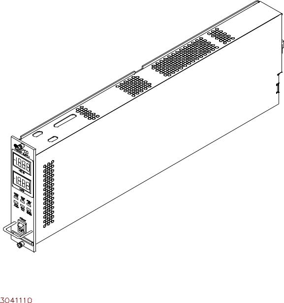
FIGURE 1-1. MST POWER SUPPLY
iv |
MST SERIES 061813 |
FIGURE 0-1.
SECTION 1 - INTRODUCTION
1.1SCOPE OF MANUAL
This manual contains instructions for the installation, operation, and maintenance of the MST series of 200 Watt, voltage and current stabilized d-c power supplies (power modules) manufactured by Kepco, Inc., Flushing, New York, U.S.A.
1.2DESCRIPTION
The Kepco MST 200 Watt Series (Figure 1-1) consists of eight, single-output models as shown in Table 1-1. MST Series Power Modules employ a switch mode preregulator for high efficiency and power density, with linear output stabilization for accuracy and resolution. MST Power Supplies (Modules) are of a modular, plug-in design whose 7" x 1-3/4” cross-section allows nine independently controlled modules to be mounted abreast in a standard (19" x 7" x 20.9") Kepco Model RA 55 rack adapter or 5 modules in a standard (9.6” x 7” x 20.9”) Kepco Model CA 400 case.
The MST Power Module is controlled digitally via the IEEE 1118 2-wire serial bus (“Bitbus”) with 12 bits of resolution over the entire voltage and current ranges. Voltage and current are displayed on LED panel meters, and read back over the control bus with an accuracy of 0.06%. Operating status is displayed on front panel LED indicators and read back over the bus.
An MST Power Module can be installed without powering down the system. Employing cur- rent-sharing for parallel operation, they may be “hot-swapped” for redundant (N+1) applications. MST Power Supplies can be operated with universal a-c input power sources (90-264Vac, 47-63Hz) and incorporate power factor correction (0.98) to meet EN 61000-3-2. MST Power Modules can also be configured in series for higher than rated output voltages (500V d-c maximum).
TABLE 1-1. MST MODEL PARAMETERS
|
OUTPUT |
OUTPUT CURRENT |
|
RIPPLE |
NOISE |
|
|||||
|
VOLTAGE |
|
Maximum (Amps) |
|
|
(mV p-p) |
(mV p-p) |
EFFICIENCY |
|||
MODEL |
Adjustment |
|
|
|
|
|
Source |
|
SW |
(Spike) |
(100% Load |
|
Range |
45 ° C |
|
55 ° C |
|
65° C |
|
120V a-c) |
|||
|
(V d-c) |
|
|
|
|
|
(max.) |
|
(max.) |
20MHz |
|
|
|
|
|
|
|
|
|
|
|
|
|
|
|
|
|
|
|
|
|
|
|
|
|
MST 6-20M |
0-6 |
20 |
|
16 |
|
12 |
2.5 |
|
5 |
50 |
51% |
|
|
|
|
|
|
|
|
|
|
|
|
MST 15-12M |
0-15 |
12 |
|
9.6 |
|
7.2 |
5 |
|
10 |
100 |
61% |
|
|
|
|
|
|
|
|
|
|
|
|
MST 25-8M |
0-25 |
8 |
|
6.4 |
|
4.8 |
5 |
|
10 |
100 |
62% |
|
|
|
|
|
|
|
|
|
|
|
|
MST 36-5M |
0-36 |
5 |
|
4.0 |
|
3.0 |
5 |
|
10 |
100 |
63% |
|
|
|
|
|
|
|
|
|
|
|
|
MST 55-3.5M |
0-55 |
3.5 |
|
2.8 |
|
2.1 |
5 |
|
10 |
100 |
64% |
|
|
|
|
|
|
|
|
|
|
|
|
MST 75.2.5M |
0-75 |
2.5 |
|
2.0 |
|
1.5 |
7.5 |
|
15 |
150 |
64% |
|
|
|
|
|
|
|
|
|
|
|
|
MST 100-2M |
0-100 |
2.0 |
|
1.6 |
|
1.2 |
7.5 |
|
15 |
150 |
66% |
|
|
|
|
|
|
|
|
|
|
|
|
MST 150-1.2M |
0-150 |
1.2 |
|
1.0 |
|
0.7 |
7.5 |
|
20 |
200 |
66% |
|
|
|
|
|
|
|
|
|
|
|
|
1.3SPECIFICATIONS
The MST Series electrical and mechanical specifications are listed in Tables 1-1 and 1-2.
MST SERIES 061813 |
1-1 |

.
TABLE 1-2. MST GENERAL SPECIFICATIONS
SPECIFICATIONS |
RATING/DESCRIPTION |
CONDITION |
||
|
|
|
|
|
|
|
|
INPUT |
|
|
|
|
|
|
A-C Voltage |
|
nominal |
100-250V a-c |
Single phase |
|
|
|
|
|
|
range |
90-264 Va-c |
Brownout Voltage ≤ 85Vrms |
|
|
|
|||
|
|
|
|
|
Frequency |
|
nominal |
50-60 Hz |
At >63 Hz, input leakage current |
|
|
|
exceeds specifications |
|
|
range |
47 – 63 Hz (400 Hz) |
||
|
|
|||
|
|
|
||
|
|
|
|
|
Input Current |
maximum |
3.6A rms |
90V a-c Input |
|
|
|
|
|
|
Current Harmonics |
|
Within EN 61000-3-2 limits |
Any source condition, rated load |
|
|
|
|
|
|
Efficiency |
minimum |
See Model Table 1-1 |
120V a-c, rated output Load |
|
|
|
|
|
|
EMI |
|
FCC Class A, CISPR 11 Class A |
Conducted Emissions |
|
|
|
|
|
|
|
|
120V a-c, |
<0.5 mA |
|
Leakage Current |
|
60Hz |
|
|
|
|
|
|
|
|
240V a-c, |
<1.0 mA |
|
|
|
|
|
||
|
|
50Hz |
|
|
|
|
|
|
|
Power Factor |
|
0.98 min. |
All source conditions, full load |
|
|
|
|
|
|
EMC |
|
Complies with IEC 61326-1, Class A |
|
|
|
|
|
|
|
|
|
|
OUTPUT |
|
|
|
|
|
|
Source Effect |
Voltage |
0.001% |
90 – 132, 176 – 264V a-c, |
|
|
|
Current |
0.005% |
any load condition |
|
|
|
|
|
Load Effect |
Voltage |
±0.002% or 0.5mV, whichever is greater |
10% to 100% Load at EMAX, |
|
|
|
|
|
any source condition |
|
|
Current |
±0.005%(1) |
10% to 100% Load at IMAX |
Temperature Effect |
Voltage |
0.01%/°C |
Any source/load condition |
|
|
|
Current |
0.02%/°C |
(0 – 45° C) |
|
|
|
|
|
Time Effect (drift) |
Voltage |
0.01% |
0.5 – 8.5 hours |
|
|
|
Current |
0.02% |
Any source/load condition |
|
|
|
|
|
Programming |
Voltage |
12 Bits, 0.024% |
% of EMAX |
|
Resolution |
|
|
|
|
|
Current |
12 Bits, 0.024% |
% of IMAX |
|
|
|
|||
Data Read Back |
Voltage |
0.1% |
% of EMAX |
|
Accuracy |
|
|
|
|
|
Current |
0.12% |
% of IMAX |
|
|
|
|||
Transient Recovery Time |
|
100 Microseconds |
Return to within stabilization |
|
|
|
|
(500 Microseconds for MST 6-20M) |
band from 50% load step |
|
|
|
|
|
Turn On/Off Overshoot |
|
None |
Any source/load condition |
|
|
|
|
|
|
Error Sense |
|
0.5V maximum/wire |
Any source/load condition |
|
|
|
|
|
|
|
|
|
MISCELLANEOUS |
|
|
|
|
|
|
Temperature |
|
0° to +65° C, start from –20°C (see Table 1-1) |
Operating |
|
|
|
|
|
|
|
|
|
–40° to +85° C |
Storage |
|
|
|
|
|
Humidity |
|
0 to 95% RH |
Non-condensing Operating & |
|
|
|
|
|
Storage |
|
|
|
|
|
Shock |
|
20G 11 msec ±50% half sine |
3 axes, 3 shocks each axis, |
|
|
|
|
|
non-operating |
|
|
|
|
|
Vibration |
|
5 – 10Hz 10mm double amplitude |
Non-operating, 1 hour each axis |
|
|
|
|
|
|
|
|
|
10 – 55 Hz 2G |
|
|
|
|
|
|
|
|
|
|
|
Altitude |
|
Sea level to 10,000 ft. |
Any source/load condition |
|
|
|
|
|
|
Isolation (Output – Case) |
|
±500 V d-c |
|
|
|
|
|
|
|
Display |
Voltage |
3.5 Digit LED, red |
Front panel, |
|
|
|
Current |
3.5 Digit LED, red |
For reference only |
|
|
|
|
|
(1) Current mode regulation is subject to an additional 0.015% settling effect as well as a d-c offset of up to 3mA based on compliance voltage
1-2 |
MST SERIES 061813 |
TABLE 1-2. MST GENERAL SPECIFICATIONS (CONTINUED)
SPECIFICATIONS |
RATING/DESCRIPTION |
CONDITION |
||
|
|
|
|
|
Status Indicators |
|
Voltage Mode |
Green LED |
|
|
|
|
|
|
|
|
Current Mode |
Amber LED |
|
|
|
|
|
|
|
|
Current Share |
Amber LED |
|
|
|
|
|
|
|
|
Output Enabled |
Green LED |
|
|
|
|
|
|
|
|
Polarity Reversed |
Green LED |
|
|
|
|
|
|
|
|
Output Fault |
Red LED |
|
|
|
|
|
|
Output Enable |
|
Built in power and sense relay |
|
|
|
|
|
|
|
Polarity Reversal |
|
Built in power and sense relay |
|
|
|
|
|
|
|
Parallel Connection |
|
N+1 redundancy, forced current share |
Currents divided equally |
|
|
|
|
|
|
Overvoltage protection |
|
Tracks output setting, power shutdown |
|
|
|
|
|
Latched, reset |
|
Overtemperature |
|
Thermostat |
||
|
by cycling source |
|||
|
|
|
||
Open sense wire |
|
Automatic detection with power shutdown |
||
|
power off |
|||
|
|
|
||
Backup current limit |
|
Tracks output current at 110% |
|
|
|
|
|
|
|
|
|
|
|
|
|
|
PHYSICAL |
|
|
|
|
|
|
|
Type of Construction |
Enclosed, plug-in style includes status LEDs, two digital |
|
||
meters, handle and ON/OFF switch |
|
|||
|
|
|
||
|
|
|
|
|
Cooling |
|
Internal D-C Cooling Fans |
Exhaust to rear |
|
|
|
|
|
|
Module |
English |
7” x 1.83” x 20” |
Refer to Figure 1-2 |
|
Dimensions |
Metric |
178 x 46.5 x 508 mm |
||
|
||||
|
|
|
|
|
Weight |
English |
8 lbs. |
|
|
|
|
|
||
Metric |
3.6 Kg. |
|
||
|
|
|||
|
|
|
|
|
Load Connection |
|
Mates with Positronic POW-R-LOK Series 6 pin connec- |
Mating connectors provided with |
|
|
tor, Kepco P/N 143-0458 (See Figure 2-6 and Table 2-5), |
MST compatible rack adapters |
||
|
|
|||
|
|
|
|
|
Source Connection |
|
Mates with Molex Minifit, Jr. Series 10 pin connector, |
Mates with a-c backplane in |
|
|
Kepco p/n 143-0544 (See Figure 2-6) |
MST compatible rack adapters |
||
|
|
|||
|
|
|
|
|
1.4FEATURES
1.4.1CONTROL/PROGRAMMING
Control of the MST Power Module is via the IEEE 1118 2-wire serial bus operating at 375KHz; as many as 27 separate modules of either the MST, MAT, MBT or BOP Series design can be addressed via the bus (see Figure 1-3). Decoders for RS232, IEEE-488 and VXI are available in modular form and stand-alone types. As shown in Figure 1-3, the following controllers are available to control of MST (and MAT) Power Modules directly from a computer.
a.Controller Model TMA PC-27 plugs into a half-card slot of a DOS-based PC and allows keyboard control of the MST via the IEEE 1118 bus.
b.Controller Model TMA 4882-27 is free-standing and allows host computers designed for RS232 or IEEE 488 bus communication to control the MST via the IEEE 1118 bus.
c.Controller Model TMA-VXI-27 plugs into a slot in a VXI chassis and allows VXI-based computers to control the MST via the IEEE 1118 bus.
d.Controller Model MST 488-27 plugs into a slot in a Model RA 55 Rack Adapter and allows host computers designed for RS232 or IEEE 488 bus communication to control the MST via the IEEE 1118 bus.
e.The MST Power Module can also be directly controlled via the keypad of the MBT Series (“G” Option) Power Supply via the IEEE 1118 bus.
MST SERIES 061813 |
1-3 |

FIGURE 1-2. MST POWER SUPPLY, MECHANICAL OUTLINE DRAWING
1-4 |
MST SERIES 061813 |
Loading...