


COMPONENT SYSTEM/COMPACT HI-FI SYSTEM
XD-951
XD-A900
XD-A700
INSTRUCTION MANUAL
KENWOOD CORPORATION
This instruction manual is used to describe multiple models listed above.
Model availability and features (functions) may differ depending on the country and sales area. ˆ
COMPACT
DIGITAL AUDIO
B60-3907-00 01 MA MC (E2,Q,M,X,Y,K,P) 99/12 11 10 9 8 7 6 5 4 3 2 1 98/12 11 10 9 8 7 6 5 4
2 Before applying power
Units are designed for operation as follows. |
|
U.S.A. and Canada ................................................................... |
AC 120 V only |
Australia .................................................................................... |
AC 240 V only |
Preparation section
 Caution : Read this page carefully to ensure safe operation.
|
XD-951/A900/A700 (En) |
Europe and U.K. ........................................................................ |
AC 230 V only |
China and Russia ..................................................................... |
AC 220 V only |
*Other countries ................................ |
AC 110-120 / 220-240 V switchable |
Application section
Knowledge sections
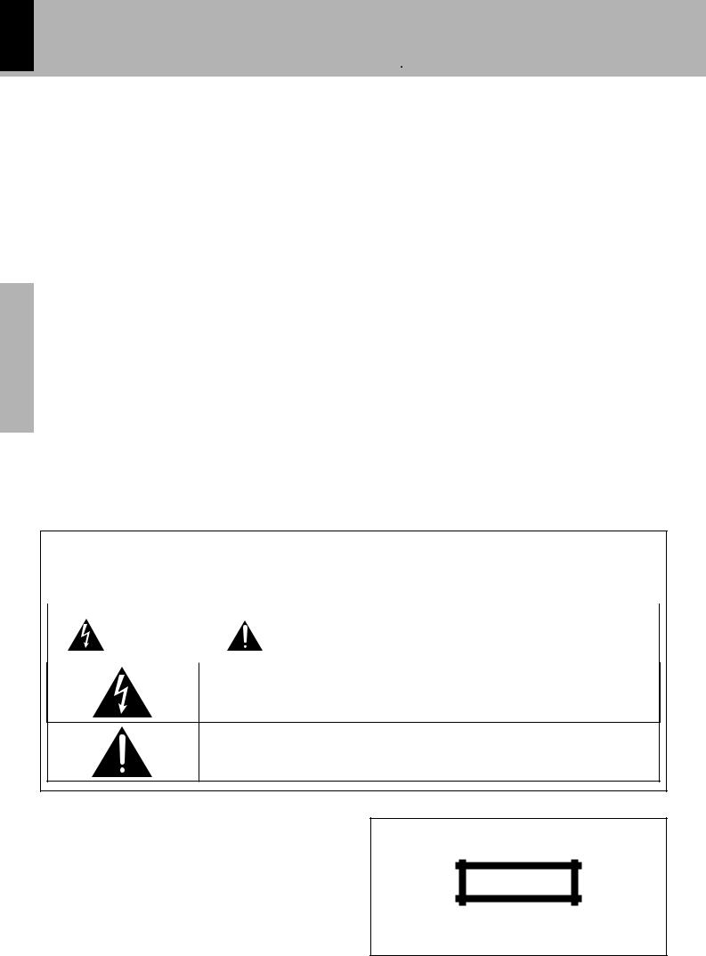
Safety precautions
WARNING : TO PREVENT FIRE OR ELECTRIC SHOCK, DO NOT EXPOSE THIS APPLIANCE TO RAIN OR MOISTURE.
|
|
|
|
|
CAUTION |
|
CAUTION: TO REDUCE THE RISK OF ELECTRIC SHOCK, DO NOT REMOVE COVER |
|
RISK OF ELECTRIC SHOCK |
|
(OR BACK). NO USER-SERVICEABLE PARTS INSIDE. REFER SERVICING TO QUALI- |
|
DO NOT OPEN |
|
FIED SERVICE PERSONNEL. |
|
|
|
|
|
|
|
|
THE LIGHTNING FLASH WITH ARROWHEAD SYMBOL, WITHIN AN EQUILATERAL TRIANGLE, IS INTENDED
TO ALERT THE USER TO THE PRESENCE OF UNINSULATED “DANGEROUS VOLTAGE” WITHIN THE
PRODUCT’S ENCLOSURE THAT MAY BE OF SUFFICIENT MAGNITUDE TO CONSTITUTE A RISK OF ELEC-
TRIC SHOCK TO PERSONS.
THE EXCLAMATION POINT WITHIN AN EQUILATERAL TRIANGLE IS INTENDED TO ALERT THE USER TO
THE PRESENCE OF IMPORTANT OPERATING AND MAINTENANCE (SERVICING) INSTRUCTIONS IN THE
LITERATURE ACCOMPANYING THE APPLIANCE.
The marking of products using lasers (Except for some areas)
CLASS 1
LASER PRODUCT
The marking is located on the rear panel and says that the component uses laser beams that have been classified as Class 1. It means that the unit is utilizing laser beams that are of a weaker class. There is no danger of hazardous radiation outside the unit.
Caution : Read the pages marked |
carefully to ensure safe operation. |
3 |
|
Before applying power |
|
|
|
|
|
XD-951/A900/A700 (En) |
|
Contents
Preparation section |
|
Before applying power ............................................ |
2 |
Safety precautions ....................................................... |
2 |
Special features ............................................................ |
4 |
Handling of discs and tapes ........................................ |
5 |
System connection (XD-951/XD-A900) .................. |
6 |
Connection of the System Accessories ..................... |
6 |
System connection (XD-A700) ................................ |
8 |
Connection of the System Accessories ..................... |
8 |
Connection of the surround speakers ........................... |
10 |
Connection of Options (Optional Parts) .................. |
11 |
Controls and indicators ......................................... |
12 |
Main Unit ..................................................................... |
12 |
Display ......................................................................... |
14 |
Remote control Unit................................................... |
15 |
Operation of remote control unit .......................... |
16 |
CHANNEL SPACE setting........................................... |
16 |
Basic section |
|
Let’s put out some sound ....................................... |
18 |
Basic use method ....................................................... |
18 |
Playback of CD ............................................................ |
20 |
Playback of tape ......................................................... |
22 |
Searching for the desired music program (DPSS).. |
25 |
Receiving broadcast station ....................................... |
26 |
Let’s record ............................................................... |
28 |
Recording (Deck B only) ............................................ |
28 |
Copying tape (Tape dubbing) ..................................... |
31 |
Application section
Playback of CD ........................................................ |
32 |
Listening in the desired sequence |
|
(program playback) .............................................. |
32 |
Repeated playback ..................................................... |
34 |
Listening to an unexpected title sequence |
|
(random playback) ................................................ |
36 |
R.D.S. (Radio Data System) |
|
(For only U.K., Europe and Russia) ....................... |
37 |
|
|
Searching for a desired program type |
|
|
|
(PTY search) ............................................................ |
38 |
|
|
To be able to listen to the desired information |
42 |
Preparation |
|
Selection of the convenient CD recording type ...... |
|||
at any time (EON) ................................................. |
40 |
|
|
Convenient CD recording ....................................... |
42 |
|
|
Recording only desired titles |
|
section |
|
(CD ONE TRACK RECORD) |
43 |
||
|
|||
Recording of an entire CD |
|
|
|
(CD RECORD) .......................................................... |
44 |
|
|
Giving preference to the tape length over the title |
|
|
|
sequence (CD EDIT) |
45 |
|
|
|
|||
Recording the programmed titles |
|
|
|
|
|
||
(CD PGM RECORD) ................................................ |
46 |
|
|
Effective Sound Adjustment ................................. |
47 |
|
|
Adjustment of balance and input level ..................... |
47 |
Basic |
|
Listening with the desired sound |
|
||
|
|
||
(equalizer function) ............................................... |
48 |
section |
|
Enjoying Sound Field Effects |
50 |
||
|
|||
DOLBY PRO LOGIC surround adjustment ................ |
51 |
|
|
DOLBY PRO LOGIC surround playback ..................... |
52 |
|
|
DOLBY 3 STEREO adjustment and play ................... |
53 |
|
|
DSP (Digital Signal Processor) playback .................. |
54 |
|
|
Enjoying Karaoke (Except for some areas)............... |
55 |
|
|
.....................................................Clock adjustment |
56 |
|
|
Timer operation ....................................................... |
57 |
|
|
Sleep timer (SLEEP) .................................................... |
57 |
|
|
Operate easy To use Timer |
|
sectionApplication |
|
(Operate easy To use Timer:O.T.T.) |
57 |
||
|
|||
Timer programming ........................................................ |
58 |
|
Knowledge section
Important Items ....................................................... |
61 |
|
|
Maintenance |
61 |
|
|
|
|||
Reference ..................................................................... |
61 |
|
|
In case of difficulty ................................................. |
62 |
sectionsKnowledge |
|
Specifications |
65 |
||
|
|||
|
|
|
4
Special features
Before applying power
XD-951/A900/A700 (En)
DOLBY Pro Logic Surround |
Q |
The Dolby Pro Logic and Dolby 3 Stereo are top-level surround modes that can reproduce the world of 3- dimensional audio.
Built in sub woofer (XD-951/XD-A900 only) |
( |
Each 3-way speaker incorporates an additional sub woofer to reproduce heavy bass more powerfully than conventional system speakers.
Preparation section
3D Wide FL display |
$ |
The easy to see graphical display features a large spectrum analyzer. A running indicator shows the operations such as CD playback and skipping at a glance.
Easy to operate, new multi control jog dial |
& |
The jog dial makes possible easy setup of CD playback, timer recording/playback and other operations while monitoring the displayed information. The same operation is also available on the remote control unit.
3-Disc carousel CD player |
) |
Three discs can be set. There are various ways for enjoyment at the time of program playback, repeat playback, random playback, etc.
Demonstration
When the power supply is restored after a power failure or the power cord is unplugged and plugged in again during use, this unit automatically starts the demonstration function (display only). During the demonstration, the display changes in sequence but the audio does not change. The demonstration can be canceled with the following procedure.
÷Press the key during demonstration to stop it.
÷Even when DEMO is ON, stations with weak radio waves are muted and their sound cannot be heard.
MODE /DEMO
To switch over the demonstration:
Turn the unit OFF (STANDBY mode) and press the key.
Each press of the key switches the demonstration as shown below.
 1 DEMO (Demonstration executed) 2 OFF (Demonstration canceled)
Application section
Knowledge sections
Unpacking
Unpack the unit carefully and make sure that all accessories are put aside so they will not be lost.
Examine the unit for any possibility of shipping damage. If your unit is damaged or fails to operate, notify your dealer immediately. If your unit was shipped to you directly, notify the shipping company without delay. Only the consignee (the person or company receiving the unit) can file a claim against the carrier for shipping damage.
We recommend that you retain the original carton and packing materials for use should you transport or ship the unit in the future.
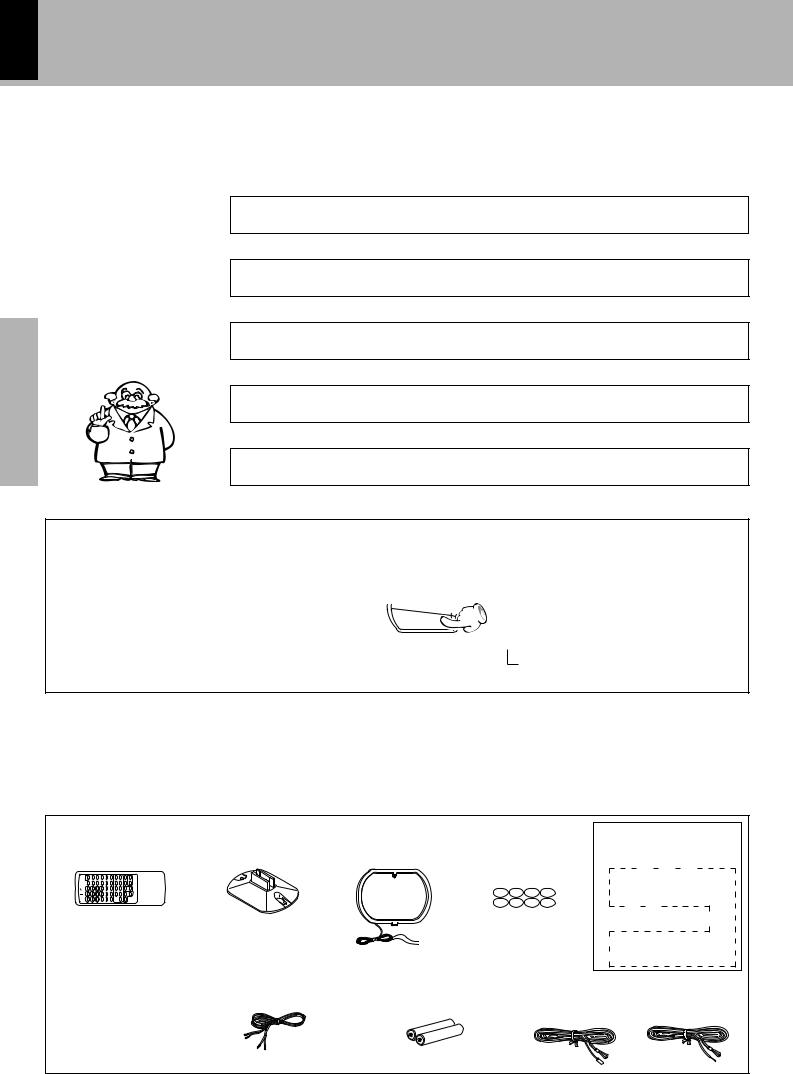
Accessories
Remote control unit (1) |
Loop antenna stand (1) |
Speaker cords (4)
XD-951/XD-A900
Speaker cords (2)
XD-A700
AM loop antenna (1) |
|
|
Surround speaker system |
|
Speaker cushions (8) |
Surround speaker (2) |
|||
|
|
|
Speaker cord (2) |
|
|
|
|
Speaker stabilizer (8) |
|
|
|
|
Wall mount hardware (2) |
|
|
|
|
Screw (4) |
|
|
|
|
Center speaker (1) |
|
|
|
|
Speaker cord (1) |
|
|
|
|
Speaker stabilizer (4) |
|
|
|
|
|
Except for CRS-N551 |
Batteries (R6/AA) (2) |
FM indoor antenna (1) |
|||
|
|
Europe and U.K. |
Other countries |
|
(Provided in the speaker package)
Before applying power 5
XD-951/A900/A700 (En)
Handling of discs and tapes
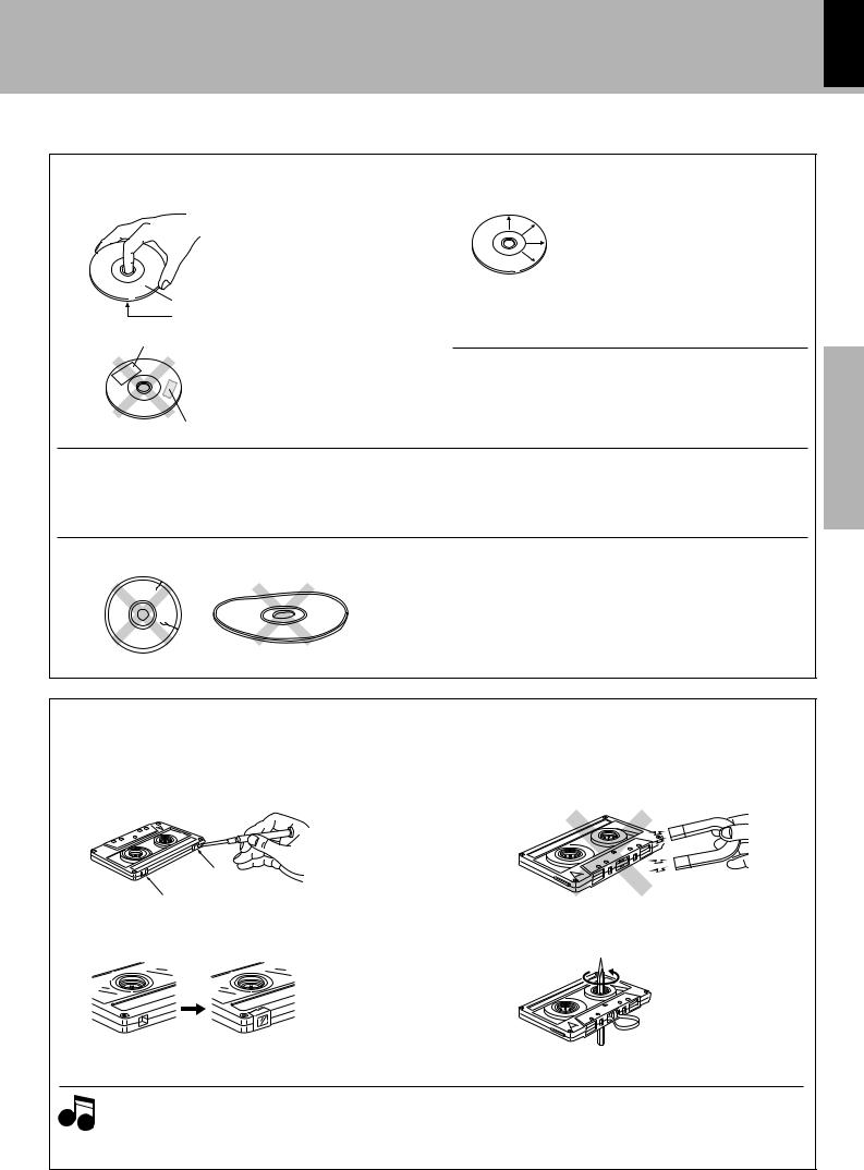
Disc handling precautions
Handling
Hold compact discs so that you do not touch the playing surface.
Label side
Playing side
Sticker, etc
Do not attach paper or tape to either the playing side or the label side of compact discs.
Sticky paste
Cleaning
If fingerprints or foreign matter become attached to the disc, lightly wipe the disc with a soft cotton cloth (or similar) from the center of the disc outwards in a radial manner.
Storage
When a disc is not to be played for a long period of time, remove it from the CD player and store it in its case.
CD accessories
The CD accessories (stabilizer, protection sheet, protection ring, etc.) which are marketed for improving the sound quality or protecting discs as well as the disc cleaner should not be used with this system because they may cause malfunction.
Discs which can be played with this unit |
CD (12 cm, 8 cm), CDV (only the audio part) |
|
÷With CD-G (CD Graphics) discs, this unit can play only the audio. |
|
÷Please do not use discs which are not round because they may |
|
cause a malfunction. |
Caution on disc used |
Never play cracked or warped disc. |
|
During playback, the disc rotates at high speed in the player. |
|
Therefore, to avoid malfunction, never use a cracked or deformed disc |
|
or a disc repaired with tape or adhesive agent. |
Do not use cleaning discs.
Please do not use commercially available cleaning discs, they may damage the internal mechanism.
section Preparation
Notes on cassette tape
Safety tab (accidental erasure prevention tab)
After an important recording has been finished, break the safety tab, to prevent the recorded contents from being erased or recorded on accidentally.
For A side
For B side
To store cassette tapes
Do not store the tapes in a place which is subject to direct sunlight, or near equipment that generates heat. Keep the cassette tapes away from any magnetic field.
N
S
When there is slack in the tape
In such a case, insert a pencil into the reel hole and wind the reel hub to remove the slack.
To re-record Apply tape only to the position where the tab has been removed.
|
1. Longer tape than 110 minutes cassette tape |
2. Endless tapes |
|
Notes |
Since longer tape than 110 minutes cassette tape is very |
Do not use an endless tape, as this could damage the mechanism of |
|
thin, the tape could adhere to the pinch roller or be easily cut. |
the unit. |
||
|
|||
|
It is recommended that these tapes not be used with this |
|
|
|
unit to prevent possible damage. |
|
section Application
sections Knowledge

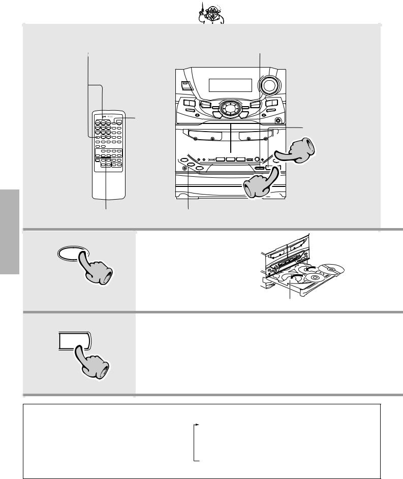
6 System connection (XD-951/XD-A900)
XD-951/A900/A700 (En)
Preparation section
Application section
Knowledge sections
Connection of the System Accessories
This is the connection method for system and accessories. Please look carefully at the illustration and connect correctly in the order of the numbers.
AM loop antenna
Malfunction of microcomputer
If operation is not possible or erroneous display appears even though all connections have been made properly, reset the microcomputer referring to “In case of difficulty”.
„
The supplied antenna is for indoor use. Place it as far as possible from the main system, TV set, speaker cords and power cord, and set it to a direction which provides the best reception.
Europe and Russia
FM |
Other countries |
75Ω |
|
|
|
|
ANTENNA |
AM |
|
GND |
FM |
|
75Ω |
2 |
|
|
|
|
|
L |
|
|
|
R |
AUX |
|
|
|
OUTPUT |
Speaker (right) |
L |
|
|
R |
AUX |
||
|
|
|
|
|
|
|
INPUT |
|
|
|
MIN. MAX. |
|
|
|
AUX INPUT |
|
|
|
LEVEL |
− |
+ |
|
|
− |
+ |
|
|
|
3 |
Red |
|
|
Black |
|
|
|
|
Blue |
|
|
Black |
|
|
GND
FM 300Ω
AM
|
+ |
– |
ANTENNA |
L |
|
|
R |
FRONT |
FM |
SPEAKERS |
|
75Ω |
|
(6-16Ω) |
|
L |
SUB WOOFER |
|
|
|
|
|
SPEAKERS |
|
R |
(12-16Ω) |
GND |
|
|
FM |
|
|
300Ω |
|
|
AM |
|
|
|
+ |
– |
|
|
CENTER |
|
|
SPEAKER |
|
|
(6-16Ω) |
|
L |
|
|
|
SURROUND |
|
|
SPEAKERS |
|
R |
(12-16Ω) |
|
|
4
|
DIGITAL |
|
|
OUT |
|
|
OPTICAL |
|
+ |
– |
|
L |
|
|
|
FRONT |
|
R |
SPEAKERS |
|
(6-16Ω) |
||
|
||
L |
SUB WOOFER |
|
|
||
|
SPEAKERS |
|
R |
(12-16Ω) |
|
+ |
– |
|
|
CENTER |
|
|
SPEAKER |
|
|
(6-16Ω) |
|
L |
SURROUND |
|
|
||
|
SPEAKERS |
|
R |
(12 -16Ω) |
Power cord
To wall AC outlet
Speaker cord
Main Unit
1 |
2 |
3 |
4 |
Twist
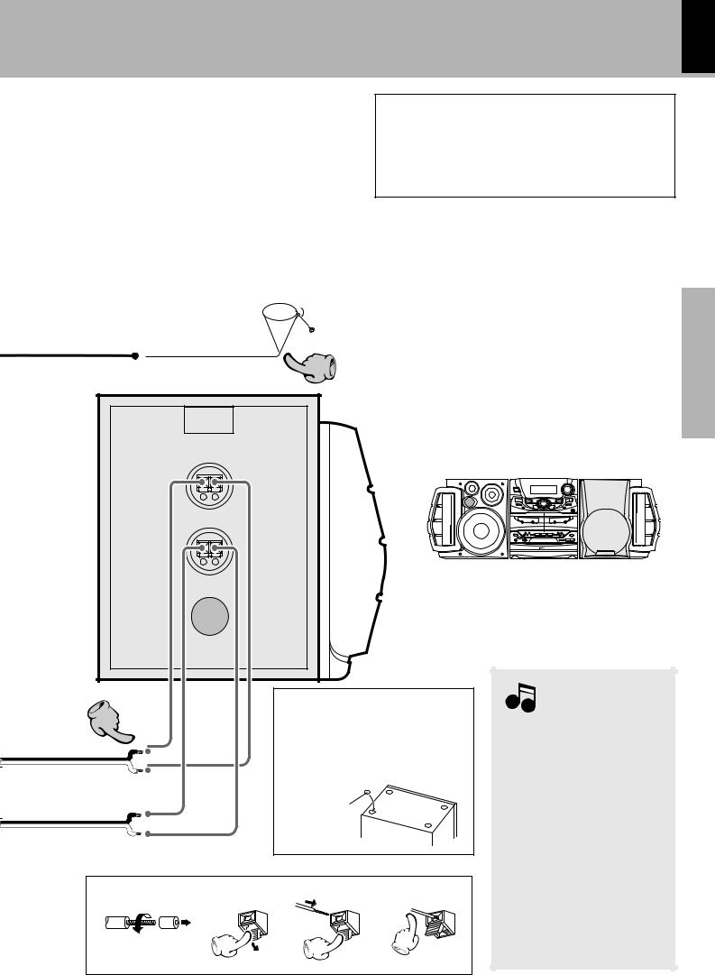
System connection (XD-951/XD-A900) 7
XD-951/A900/A700 (En)
Caution regarding placement (Except for U.S.A. and Canada)
To maintain proper ventilation, be sure to leave a space around the unit (from the largest outer dimensions including projections) equal to, or greater than, shown below.
rear panel: 10 cm
FM indoor antenna
The accessory antenna is for temporary indoor use only. For stable signal reception we recommend using an outdoor antenna. Remove the indoor antenna if you connect one outdoors.
|
1 |
Speaker (left) |
|
− |
+ |
− |
+ |
1Strip the coating from the tip of cord and twist the conductor.
2Connect to the antenna terminal.
3Locate the position providing good reception condition.
4Fix the antenna.
WOOFER |
SUPER |
|
WOOFER |
||
RSUPE |
||
|
The external view is variable depending on the model and marketing destination area.
|
Before connecting the Front |
3 |
Speakers |
|
Stick the supplied front speaker cushions |
|
to the bottom of the front speakers to sta- |
|
bilize the speakers and prevent them from |
|
slipping. |
|
Speaker cushion |
Speaker Unit
1 |
2 |
3 |
4 |
Twist
Notes
1.In case an associated system component is connected, also read the instruction manual of the component.
2.Never short-circuit the + and – speaker cords.
3.If the left and right speaker connections or the + and – polarity are inverted, the sound will be unnatural with unclear positioning of musical instruments, etc. Be sure to connect them without mistake.
4.Be sure to insert all connection cords securely. If their connections are imperfect, the sound may not be produced or noise may interfere.
5.Before plugging or unplugging a connection cord, be sure to unplug the power cord from the wall AC outlet. If connection cords are plugged or unpluggedwiththepowercordleftplugged in, malfunction or damage may result.
section Preparation
section Application
sections Knowledge
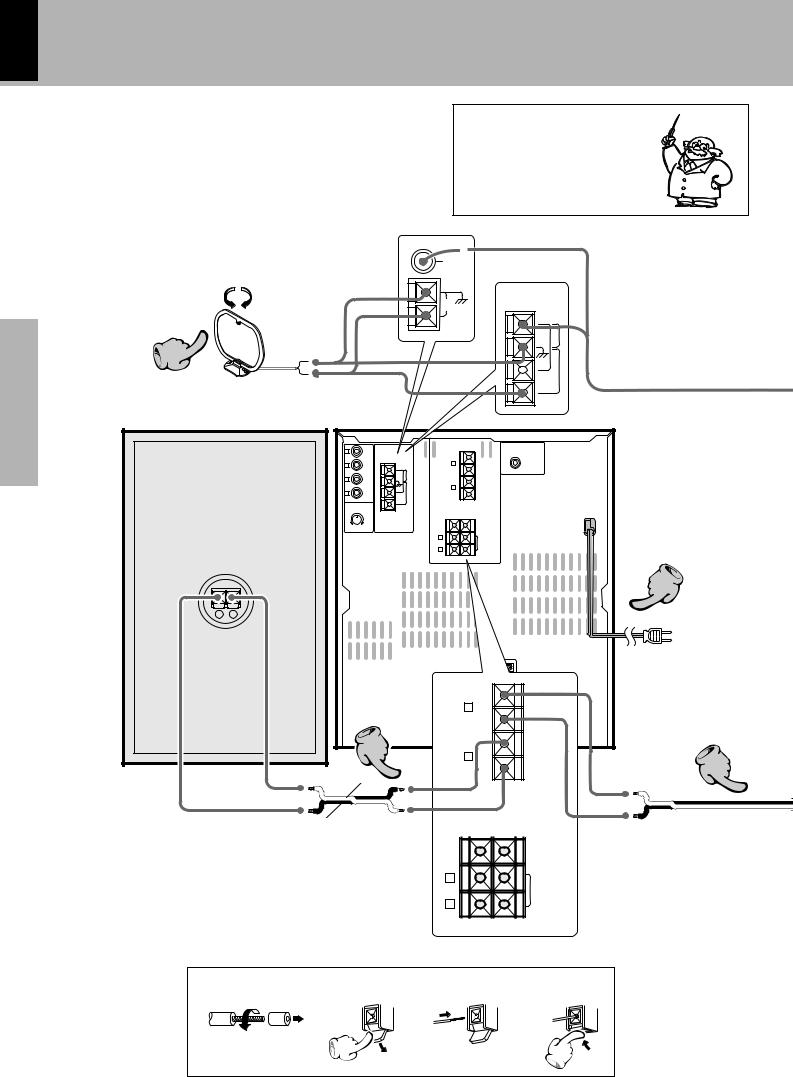
8 System connection (XD-A700)
XD-951/A900/A700 (En)
Preparation section
Application section
Knowledge sections
Connection of the System Accessories
This is the connection method for system and accessories. Please look carefully at the illustration and connect correctly in the order of the numbers.
AM loop antenna
Malfunction of microcomputer
If operation is not possible or erroneous display appears even though all connections have been made properly, reset the microcomputer referring to “In case of difficulty”.
„
The supplied antenna is for indoor use. Place it as far as |
Europe and Russia |
||||
possible from the main system, TV set, speaker cords and |
|
|
|
|
|
power cord, and set it to a direction which provides the |
|
|
|
|
|
best reception. |
FM |
|
75Ω |
Other countries |
|
|
|
|
|
|
|
|
|
|
ANTENNA |
|
|
|
|
AM |
|
|
|
|
|
|
|
GND |
|
FM |
|
|
|
|
|
|
|
|
|
|
|
|
|
|
|
|
75Ω |
2 |
|
|
|
|
|
|
GND |
|
|
|
|
|
|
|
FM |
|
|
|
|
|
|
|
300Ω |
|
|
|
|
|
|
|
AM |
|
L |
ANTENNA |
|
+ |
|
|
|
|
|
|
|
|
|
SUPER |
|
|
|
|
|
L |
|
|
WOOFER |
|
R |
AUX |
FM |
– |
|
|
PRE OUT |
|
|
OUTPUT |
75Ω |
|
|
|
|
|
|
|
|
|
FRONT |
|
|
|
L |
|
|
|
|
SPEAKERS |
|
|
|
|
– |
|
(6-16Ω) |
|
|
|
|
|
|
|
|
|
|
|
|
|
GND |
R |
|
|
|
|
|
|
+ |
|
|
|
|
|
R |
AUX |
FM |
|
|
|
|
|
|
|
|
|
|||
|
|
INPUT |
300Ω |
|
|
|
|
|
|
AUX |
AM |
|
|
|
|
|
|
INPUT |
|
|
|
|
|
|
|
LEVEL |
|
+ |
– |
|
|
|
|
|
|
|
|
||
|
|
|
|
|
|
– CENTER |
|
|
|
MIN. MAX. |
|
|
|
SPEAKER |
|
Speaker (right) |
|
|
|
|
(6-16Ω) |
|
|
|
|
L |
|
(12-16Ω) |
|
||
|
|
|
|
|
|
SURROUND |
|
|
|
|
|
|
|
SPEAKERS |
|
|
|
|
|
R |
|
|
|
− |
+ |
|
|
|
|
|
|
|
|
|
|
|
|
|
DIGITAL |
|
|
|
|
|
|
|
OUT |
|
|
|
|
|
|
|
OPTICAL |
|
|
|
|
|
|
+ |
|
|
|
|
|
|
L |
– |
|
|
|
|
|
|
|
FRONT |
|
|
|
|
|
|
|
|
|
|
|
3 |
|
|
R |
– |
SPEAKERS |
|
|
|
|
(6-16Ω) |
|||
|
|
Red |
|
|
|
+ |
|
|
|
|
|
|
|
|
|
|
Black |
|
|
|
|
+ |
– |
|
|
|
|
|
|
||
|
|
|
|
|
|
|
– SPEAKERCENTER |
|
|
|
|
|
|
|
(6-16Ω) |
|
|
|
|
L |
|
|
|
|
|
|
|
|
|
|
SURROUND |
|
|
|
|
|
|
|
SPEAKERS |
|
|
|
|
R |
|
|
(12-16Ω) |
|
|
|
|
|
|
|
|
Main Unit |
|
|
|
|
|
|
|
1 |
2 |
|
|
3 |
|
|
4 |
4
Power cord
To wall AC outlet
3
Speaker cord
Twist
System connection (XD-A700) 9
XD-951/A900/A700 (En)
Caution regarding placement
To maintain proper ventilation, be sure to leave a space around the unit (from the largest outer dimensions including projections) equal to, or greater than, shown below.
rear panel: 10 cm
FM indoor antenna
The accessory antenna is for temporary indoor use only. For stable signal reception we recommend using an outdoor antenna. Remove the indoor antenna if you connect one outdoors.
1Strip the coating from the tip of cord and twist the conductor.
1  2Connect to the antenna terminal.
3Locate the position providing good reception condition.
4Fix the antenna.
Speaker (left)
− |
+ |
The external view is variable depending on the model and marketing destination area.
Before connecting the Front
Speakers
Stick the supplied front speaker cushions to the bottom of the front speakers to stabilize the speakers and prevent them from slipping.
Speaker cushion
Speaker Unit
1 |
2 |
3 |
4 |
Twist
Notes
1.In case an associated system component is connected, also read the instruction manual of the component.
2.Never short-circuit the + and – speaker cords.
3.If the left and right speaker connections or the + and – polarity are inverted, the sound will be unnatural with unclear positioning of musical instruments, etc. Be sure to connect them without mistake.
4.Be sure to insert all connection cords securely. If their connections are imperfect, the sound may not be produced or noise may interfere.
5.Before plugging or unplugging a connection cord, be sure to unplug the power cord from the wall AC outlet. If connection cords are plugged or unpluggedwiththepowercordleftplugged in, malfunction or damage may result.
section Preparation
section Application
sections Knowledge
10
Connection of the surround speakers
System connection (XD-951/XD-A900/XD-A700)
XD-951/A900/A700 (En)
Preparation section
Application section
Do not plug the power cord into the power outlet until all of the required connections have been made.
Speaker Unit
1 |
2 |
3 |
Main Unit
Surround speaker system (supplied)
Surround speaker |
Center speaker |
Surround speaker |
|
− + |
− + |
− + |
1 |
2 |
3 |
|
|
|
+ |
– |
L |
ANTENNA |
|
L |
|
|
|
|
R |
FRONT |
R |
|
FM |
SPAKERS |
|
|
AUX |
75Ω |
|
(6-16Ω) |
|
OUTPUT |
|
|
|
L |
|
|
L |
SUB WOOFER |
|
|
|
||
|
|
|
|
SPEAKERS |
|
|
|
R |
(12-16Ω) |
|
|
GND |
|
|
R |
AUX |
FM |
|
|
|
|
|
||
|
INPUT |
300Ω |
|
|
|
|
AM |
|
|
|
|
|
+ |
– |
|
MIN. MAX. |
|
|
CENTER |
|
AUX INPUT |
|
|
|
|
LEVEL |
|
|
SPEAKER |
|
|
|
(6-16Ω) |
|
|
|
|
L |
|
|
|
|
|
SURROUND |
|
|
|
|
SPEAKERS |
|
|
|
R |
(12-16Ω) |
|
|
|
|
Dolby Pro Logic
Dolby Pro Logic is a specially encoded 2 channel surround format designed to provide theater-like surround sound from Dolby Surround encoded sources (such as video and Laserdisc software marked 
 ). This unit is equipped with a Dolby Surround decoder to let you enjoy the wide variety of currently available Dolby Surround home video software.
Center speaker
Subwoofer*
Front Speaker
Surround speakers (monaural signal)
* Optional in this mode.
+ |
– |
|
CENTER |
|
SPEAKER |
|
(6-16Ω) |
L |
SURROUND |
|
|
|
SPEAKERS |
R |
(12-16Ω) |
|
Dolby 3 Stereo
Dolby 3 Stereo is available for systems that do not set surround speakers. When in the Dolby 3 Stereo mode the surround information is redirected to the front left and right speakers. This mode is designed for use with Dolby Surround program sources, but can also improve sound field unity for programs that are not Dolby Surround edcoded. Dialog positioning and sound image definition, however, may not be as accurate when used with programs that are not Dolby Surround edcoded.
Center speaker
Subwoofer*
Front Speaker
* Optional in this mode.
Knowledge sections
Recommended speaker installation
It is recommended that the surround speakers are installed straight to the left and right of the listening position or slightly behind, at a height of about 1 meter higher than the listener’s ears. Each surround speaker should be installed so that the longer sides are horizontal.
How to use the speaker stabilizer (cushions)
When the surround speaker system installation is unstable due to the floor condition, apply the provided stabilizer (cushions) on four positions on the bottom of each speaker. (Except for CRS-N551)
Hanging on a wall
The surround speakers can be hung on a wall.
When hanging the surround speakers, select a rigid and hard place on the wall which can withstand the weight of the speakers.
1.Attach the provided mounting hardware onto the rear panel of each speaker using the provided screw. (Except for CRS-N551)
2.Install a screw, which is commercially available, with sufficient strength on the wall. When screwing in, leave the head and upper stem of the screw projected by 7 to 9 mm from the wall surface.
3.Mount each speaker by hooking up the hole of the speaker rear panel on the screw attached to the wall.
4.Check that the speakers are firmly mounted.
System connection (XD-951/XD-A900/XD-A700) 11
XD-951/A900/A700 (En)
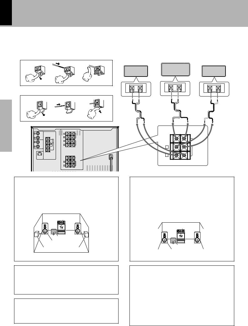
Connection of Options (Optional Parts)
Connect separately sold parts as shown in the figure.
Do not plug the power cord into the power outlet until all of the required connections have been made.
FM outdoor antenna
Lead the 75Ω coaxial cable connected to the FM outdoor antenna into the room and connect it to the FM 75Ω termimal.
|
Other countries |
|
ANTENNA |
10mm 10mm |
FM |
75Ω |
|
|
GND |
|
FM |
Antenna adapter |
300Ω |
|
|
(optional) |
AM |
|
FM |
|
|
|
|
|
|
|
75Ω |
|
|
|
|
|
|
|
|
|
|
|
|
|
Super woofer |
|
AM |
|
|
|
|
|
Extremely low sound is played back pow- |
|
GND |
|
|
|
|
|
erfully. This can be used with any type of |
|
|
|
|
|
|
|
|
Europe and Russia |
|
|
|
+ |
|
|
playback. |
L |
|
ANTENNA |
|
SUPER |
(XD-A700 only) |
||
|
R |
AUX |
FM |
L |
|
PRE OUT |
|
|
|
|
|
|
|
WOOFER |
|
|
|
OUTPUT |
75Ω |
– |
|
|
|
|
|
|
|
FRONT |
|
|
|
|
|
|
|
|
|
SUPER |
|
|
L |
|
|
– |
SPEAKERS |
|
|
|
|
|
(6-16Ω) |
|
WOOFER |
||
|
|
|
|
|
|
||
|
|
|
GND |
R |
|
|
PRE OUT |
|
R |
|
+ |
|
|
||
|
AUX |
FM |
|
|
|
||
|
|
|
|
|
|||
|
|
INPUT |
300Ω |
|
|
|
|
|
|
AUX |
AM |
|
|
|
|
|
|
INPUT |
|
|
|
|
|
|
|
LEVEL |
|
+ |
– |
|
|
|
|
|
|
|
|
||
AUX OUTPUT |
|
|
|
|
– CENTER |
|
|
|
MIN. MAX. |
|
|
SPEAKER |
|
|
|
|
|
|
|
|
(6-16Ω) |
|
|
(Except for some areas) |
|
|
|
L |
(12-16Ω) |
|
|
|
|
|
|
|
SURROUND |
|
|
|
|
|
|
|
SPEAKERS |
|
|
|
|
|
|
R |
|
|
|
L |
|
|
|
|
|
|
|
R |
AUX |
|
|
|
|
|
|
|
|
|
|
|
|
|
|
|
OUTPUT |
|
|
|
|
|
|
L |
|
|
|
|
|
|
|
R |
AUX |
|
|
|
|
|
|
|
|
|
|
|
|
|
|
|
INPUT |
|
|
|
|
DIGITAL |
|
|
|
|
|
|
|
OUT |
|
|
|
|
|
|
|
OPTICAL |
|
|
|
|
|
|
|
|
Connect to AUX jacks. |
Audio input |
Audio output |
|
Optical-fiber cable |
MD recorder |
|
(Provided with the MD |
|
Video deck |
recorder) |
|
Monitor TV |
|
Notes
1.All of the optical-fiber cables sold in audio stores cannot always be used. If the cable you purchased cannot be connected to this unit, please consult your dealer or KENWOOD distributor.
2.Insert the optical-fiber cable straight into the connector until it clicks.
3.Be sure to attach the protection cap when the connector is not used.
4.Never band or bundle the optical-fiber cable.
(Except for U.S.A. and Canada)
DIGITAL OUT jack (OPTICAL)
If necessary, remove the cap and plug the optical-fiber cable (optional).
DIGITAL
OUT
OPTICAL
Optical-fiber cable
Cap
section Preparation
section Application
sections Knowledge
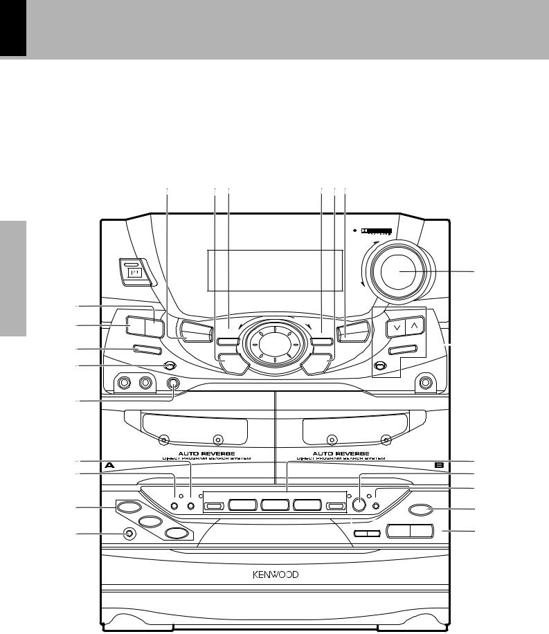
12 Controls and indicators
XD-951/A900/A700 (En)
Main Unit
The external view is variable depending on the model and marketing destination area.
|
|
POWER (For U.S.A. and Canada) |
|
|
|
|
|
|
|
|||
|
|
8 |
9 0 ! |
@ |
# |
$%^& |
|
|
|
|||
|
|
|
|
|
|
MINI HiFi COMPONENT SYSTEM |
|
|
|
|
||
|
|
|
|
|
|
|
|
|
SRS ( ) |
|
|
|
|
|
|
|
|
|
|
|
|
UP |
|
VOLUME |
|
|
|
|
|
|
|
|
|
|
|
|
|
|
section |
|
|
|
|
|
|
|
|
|
|
CONTROL |
|
1 |
|
|
|
|
|
|
|
|
|
|
* |
|
Preparation |
|
3 STEREO |
|
|
|
|
|
|
|
|||
2 |
ON/STANDBY |
PRO LOGIC |
|
|
|
|
DOWN |
|
|
|
||
|
|
|
|
|
|
|
|
|
|
|
||
|
|
|
|
|
|
|
|
MULTI |
|
TUNING |
|
|
|
3 |
|
|
|
|
|
|
|
|
|
|
|
|
EX. |
|
|
|
|
|
CONTROL |
|
|
|
|
|
|
|
|
|
|
|
|
|
|
|
|
||
|
|
|
|
|
|
|
|
|
|
|
|
|
|
|
BASS SOUND |
|
TIMER |
|
|
|
|
CD PGM |
|
|
|
|
|
|
|
MODE |
LISTEN MODE |
|
SRS 3D |
DUBBING |
|
|
|
|
|
|
|
|
/DEMO |
|
|
|
|
|
|
|
|
|
|
DISPLAY |
|
|
|
|
|
|
|
|
( |
|
|
4 |
|
|
|
|
|
|
|
BAND |
|
||
|
|
|
|
|
|
|
|
|
|
|
|
|
|
5 |
INPUT |
|
|
SET |
|
|
ENTER |
|
AUTO |
|
|
|
|
1– MIC –2 |
|
|
|
|
|
|
|
|
PHONES |
|
|
6 |
MIC |
|
|
|
|
|
|
|
|
|
) |
|
VOL. |
|
|
|
|
|
|
|
|
|
||
|
|
|
|
|
|
|
|
|
|
|
|
|
|
|
MIN |
MAX |
|
|
|
|
|
|
|
|
|
|
7 |
|
|
|
|
|
|
|
|
|
|
|
|
¡ |
0 |
|
|
|
|
|
|
|
|
0 |
¢ |
|
OPEN |
|
|
|
|
|
|
|
|
OPEN |
||
|
|
PUSH |
|
|
|
|
|
|
|
|
PUSH |
|
|
™ |
|
|
|
|
|
|
|
|
|
REC/ |
|
|
£ |
PLAY |
|
|
|
|
|
|
|
|
PLAY |
§ |
|
|
|
|
|
|
|
|
|
|
|
||
|
|
|
|
|
|
|
|
|
|
|
|
¶ |
section |
• |
REV.MODE |
DOLBY NR |
|
2 |
7 |
3 |
REC/ARM |
|
|
|
|
DISC 1 |
|
|
1 |
¡ A/B |
|
0 |
⁄ |
|||||
|
|
|
|
|||||||||
|
|
|
|
|
|
|
|
|
|
|
||
Application |
|
DISC 2 |
|
|
|
|
|
|
|
|
|
|
ª |
DISC SKIP |
DISC 3 |
|
|
|
|
|
4 ¢ |
7 |
6 |
¤ |
|
|
|
|
|
|
|
|||||||
|
|
|
|
|
|
|
|
|
|
|
|
|
|
º |
|
|
|
|
|
|
|
|
|
|
|
Knowledge sections
Controls and indicators 13
XD-951/A900/A700 (En)
Receiver
1ON/STANDBY ( |
|
|
|
POWER) key |
* !LISTEN MODE key/Indicator |
Q |
||
|
||||||||
|
|
|
||||||
|
||||||||
Power ON/OFF switching is executed. |
|
Used for setting the surround modes and sound field effects. |
||||||
2SOUND key |
|
i @DISPLAY |
$ |
|||||
Used for the equalizer mode setting, etc. |
|
#MULTI CONTROL jog dial |
& |
|||||
3EX. BASS (Extra bass) key |
( |
|||||||
Used for selection of various modes. |
|
|||||||
Switches the extra bass play on and off. |
|
$SRS 3D key/Indicator |
p |
|||||
4DISPLAY key |
|
i |
||||||
|
Switches the SRS 3D play on and off. |
|
||||||
Switches the displayed information. |
|
%ENTER key |
( |
|||||
5INPUT key |
|
* |
||||||
|
Used for entering a selected mode in memory or executing it. |
|||||||
Press to select the input source. When TAPE or CD is selected, |
^DUBBING key |
⁄ey |
||||||
playback starts automatically provided that a tape or disc has already |
||||||||
Used for tape dubbing or CD recording onto tape. |
||||||||
been loaded. |
|
|
||||||
|
|
&CD PGM key |
¤ |
|||||
6MIC 1, MIC 2 jacks (Except for some areas) |
T |
|||||||
For connection of a microphone (optional). |
|
Used for programming CD tracks. |
|
|||||
|
*VOLUME CONTROL knob |
* |
||||||
7MIC VOL. knob (Except for some areas) |
T |
|||||||
At the time of mic mixing , this knob controls the volumes of the |
This is used for volume adjustment. |
|
||||||
(Tuner operation keys |
§¶ |
|||||||
microphones. |
|
|
||||||
8MODE/DEMO key |
4(up |
TUNING keys |
|
|||||
Used for setting or selection of various modes. |
|
Press to select a radio station. |
|
|||||
|
BAND key |
|
||||||
The items which can be selected differ according to the status at that |
|
|||||||
time. |
|
|
Press to switch the receiving band. |
|
||||
When power is STANDBY: |
Switches the demonstration on and |
AUTO key |
|
|||||
|
|
|
|
off. |
|
Switches the tuning mode. |
|
|
9TIMER key |
YUI )PHONES jack |
* |
||||||
Used for time adjustment, timer setting, etc. |
|
For connection of a headphone (optional). |
|
|||||
0SET key |
|
( |
|
|
||||
Used for setting of various modes or establishing a selection.
Cassette deck unit
¡A deck cassette holder
Press the area marked 0 PUSH OPEN to load or eject a tape.
™DOLBY NR key |
£ |
Dolby noise reduction ON/OFF switching is executed.
£REV. MODE key |
£ |
The reverse mode of the deck (both sides, repeated, one side) is switched.
¢B deck cassette holder
Press the area marked 0 PUSH OPEN to load or eject a tape.
Cassette deck operation keys |
™£ |
Play (2 3) keys |
|
Stop (7) key |
|
Fast forward and rewind (1 ¡) keys |
|
§A/B key |
™ |
Press to select the deck to be operated. |
|
¶REC/ARM key |
ª⁄ |
Press to start recording. Pressing the key during recording stops it after leaving a non-recorded space (blank) of about 4 seconds.
section Preparation
section Application
CD player unit
•DISC SELECTOR keys |
¡ |
The disc for playback (or recording) is selected.
ªDISC SKIP key |
¡ |
The disc for playback (or recording) is selected. This is also used for insertion of a CD to the inside of the disc tray.
ºDisc tray |
) |
Three discs can be stored.
⁄OPEN/CLOSE (0) key
The disc tray is opened and closed.
¤CD operation keys Play/pause (6) key Stop (7) key
Skip (4 ¢) keys
)
)¡
sections Knowledge
14
Display
Controls and indicators
XD-951/A900/A700 (En)
(The displays given in this manual are approximations only. They may differ from what actually appears on the display.)
Preparation section
1 2 3 4
|
|
|
|
|
|
|
|
|||
R.D.S EON |
**** ** ** * * |
|
|
|
|
|||||
|
|
|
|
|
|
|
|
|
||
TP TA PTY |
|
|
|
|
|
|
|
|
|
|
NEWS INFO. |
|
|
|
|
|
|
|
|
|
|
P.B.C. STEREO |
|
|
|
|
|
O.T.T. PROG.12 |
|
5 |
||
ECHO |
1 |
2 |
3 |
NR |
|
SLEEP |
|
|||
|
|
|||||||||
|
|
|
|
|
|
|||||
|
|
|
|
|
|
|
|
|
|
|
|
|
|
|
|
|
|
|
|
|
|
|
|
|
|
|
|
|
|
|
|
|
|
|
|
|
|
|
|
|
|
|
|
|
|
|
|
|
|
|
|
|
|
|
|
|
|
|
|
|
|
|
|
|
|
|
|
|
|
|
|
|
|
|
|
|
|
|
|
|
|
|
|
|
|
|
|
|
|
|
|
|
|
|
|
|
|
|
|
|
|
|
|
|
|
|
|
|
|
|
|
|
|
|
|
! 0 9 8 7 |
6 |
|
|
|
||||||||||
Application section
1RDS-related indicators (For U.K., Europe and Russia)
2Tuner and applied CD operation indicators
This section contains the indicators of the tuner operations and applied CD operations.
3Character information display
Displays the input selection, frequency, volume level, etc.
4Tone and sound field-related indicators
5Timer-related indicators
6Cassette deck indicators
This section contains the cassette deck operation indicators. The indicated information includes the tape reverse mode and tape transport direction.
7CD player indicators
This section displays the CD playback and pause mode information as well as the disc number being played.
8Track number indicators
Indicates the CD track number being played.
9Spectrum analyzer display
0Running indicator
This indicator rotates according to the operation modes during operation of the CD player, cassette deck, etc. It also shows the approximate sound level during volume control.
!Guideline
Knowledge sections
Blinks during the setting of an item using the jog dial. |
& |
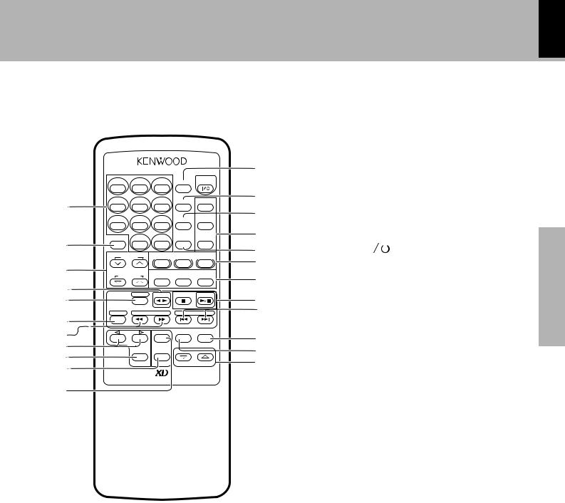
Remote control Unit
The keys on the remote control unit with the same names as on the main unit have the same function as the keys on the main unit.
@
|
|
|
POWER |
# |
|
1 |
2 |
3 |
TIME |
|
|
|
|
||||
4 |
5 |
6 |
REPEAT EQ ON/OFF |
$ |
|
1 |
|
|
|
|
% |
|
|
|
|
|
|
7 |
8 |
9 |
RANDOM SRS 3D |
|
|
DISC SKIP |
0 |
+10 |
TEST TONE EX. BASS |
^ |
|
|
|||||
2 |
|
|
|
|
& |
|
|
DOLBY |
DOLBY |
|
|
CENTER |
|
|
|||
PRO LOGIC |
3 STEREO STEREO |
* |
|||
3 |
|
|
|
|
|
|
TA/NEWS/ |
|
|
( |
|
SURROUND |
INFO. |
RDS DISP. |
PTY |
||
4 |
A/B |
TAPE |
|
CD |
|
5 |
|
) |
|||
|
|
|
|
||
BAND |
TUNING |
P.CALL |
|
¡ |
|
6 |
|
|
|
|
|
7 |
|
SET |
MUTE INPUT |
™ |
|
|
|
||||
8 |
|
|
VOLUME |
||
|
|
£ |
|||
|
|
|
|||
9 |
MENU |
ENTER |
|
|
|
|
|
|
|
¢ |
|
0 |
|
|
|
|
|
|
|
|
|
|
|
REMOTE CONTROL UNIT RC-951R
!
Europe, U.K. and Russia : RC-951R |
Model: See left. |
Other countries : RC-951 |
Infrared ray system. |
1Numeric keys |
¡ |
Used as number keys when the input is CD or TUNER.
2DISC SKIP key |
¡ |
3Surround volume adjustment keys |
WE |
4Cassette deck operation (2 3) key |
™ |
5A/B key |
™ |
6BAND key |
§ |
7TUNING/CD/cassette (1 ¡) keys |
¡£§ |
8Multi menu up/down keys |
& |
Controls and indicators 15
XD-951/A900/A700 (En)
9MENU key |
& |
Used to switch the function of the MULTI CONTROL keys.
The function items that can be selected with the MULTI CONTROL keys are variable depending on the current operation status. Items such as CD PGM, DUBBING, SOUND, DISPLAY, TIMER, LISTEN MODE and MODE are selected using keys 8.
0ENTER key |
( |
!SET key |
( |
@TIME key |
) |
Press to switch the time information on the CD player unit.
#ON/STANDBY ( |
|
|
POWER) key |
* |
Preparation |
|
|
||||||
|
|
|||||
Power ON/OFF switching is executed. |
|
|||||
|
|
|||||
$REPEAT key |
|
› |
|
|||
Used for repeated playback of a CD. |
|
|
||||
%RANDOM key |
|
fl |
section |
|||
For CD playback, switching is executed between random playback |
||||||
|
||||||
and normal playback. |
|
|
|
|||
^Tone and sound field-related keys |
|
|
||||
EQ. ON/OFF key |
|
i |
|
|||
Press to switch the equalizer ON and OFF.
SRS 3D key |
p |
EX. BASS key |
( |
&TEST TONE key |
W |
*Surround operation keys |
QWE |
(RDS-related keys (For U.K., Europe and Russia) |
|
TA/NEWS/INFO. key |
‚ |
Used for automatic reception of transmissions of a certain content.
RDS DISP. key |
‡ |
The display contents are switched during reception of RDS broadcasts.
PTY key |
° |
This is used to specify the program type when searching for a station.
)CD operation keys
CD play/pause (6) key Stop (7) key
¡P.CALL (Preset Call)/skip (4 ¢) keys
Used to recall a preset radio station.
During CD playback, press to skip CD tracks.
™INPUT key
£MUTE key
This is used to mute the sound temporarily.
¢VOLUME keys
§ |
Application |
|
¡ |
|
|
* |
section |
|
( |
||
|
||
* |
|
sections Knowledge
16 Operation of remote control unit
XD-951/A900/A700 (En)
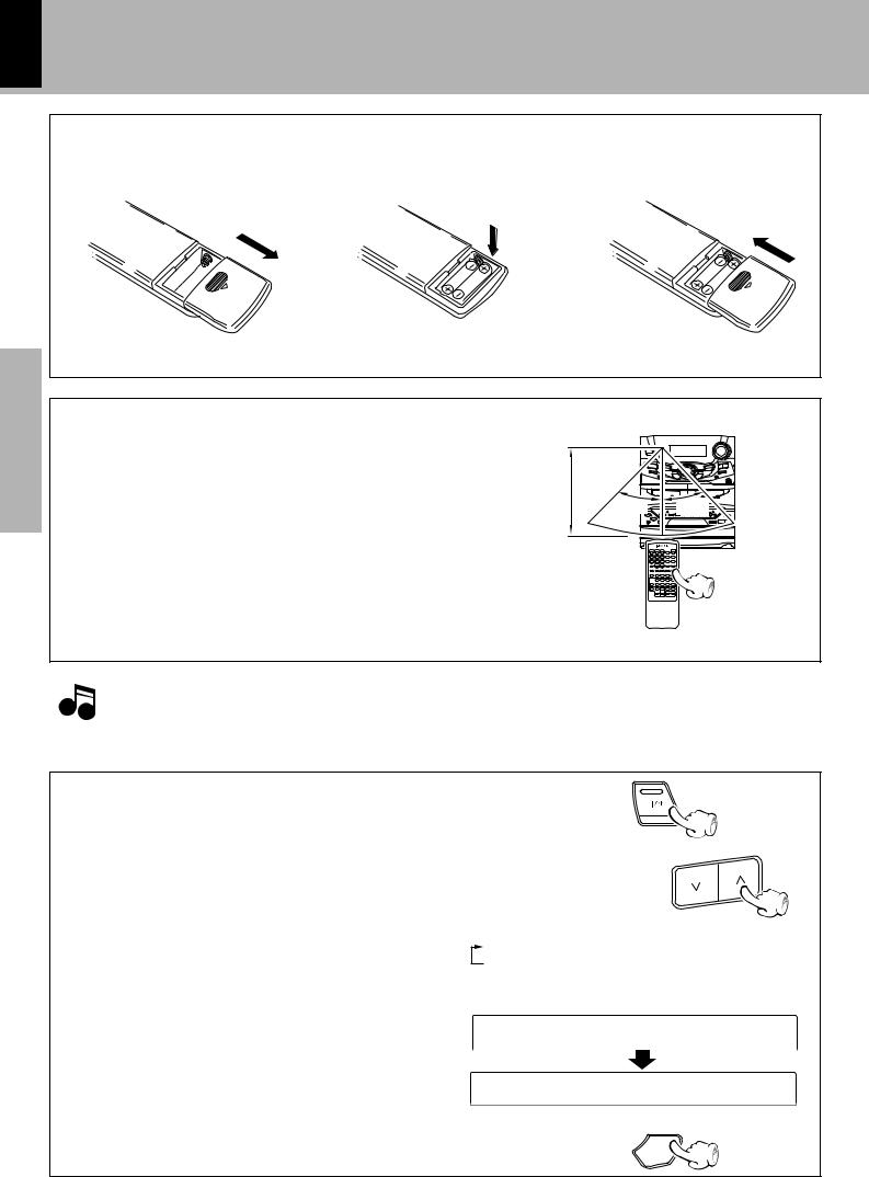
Loading batteries
1 Remove the cover. |
2 Insert batteries. |
3 Close the cover. |
Preparation section
÷Insert two R6 (“AA”-size) batteries following the polarity indications.
Operation
Plug the power cord into the mains power outlet and press the on/standby ( 

 POWER) key of the remote control unit to turn power ON. After the power has been turned ON, press the desired key.
To turn power off, press the on/standby ( 

 POWER) key again. The system enters the standby mode in which only the time display is lit.
÷When pressing more than one remote control keys successively, press the keys securely by leaving an interval of 1 second or more between keys.
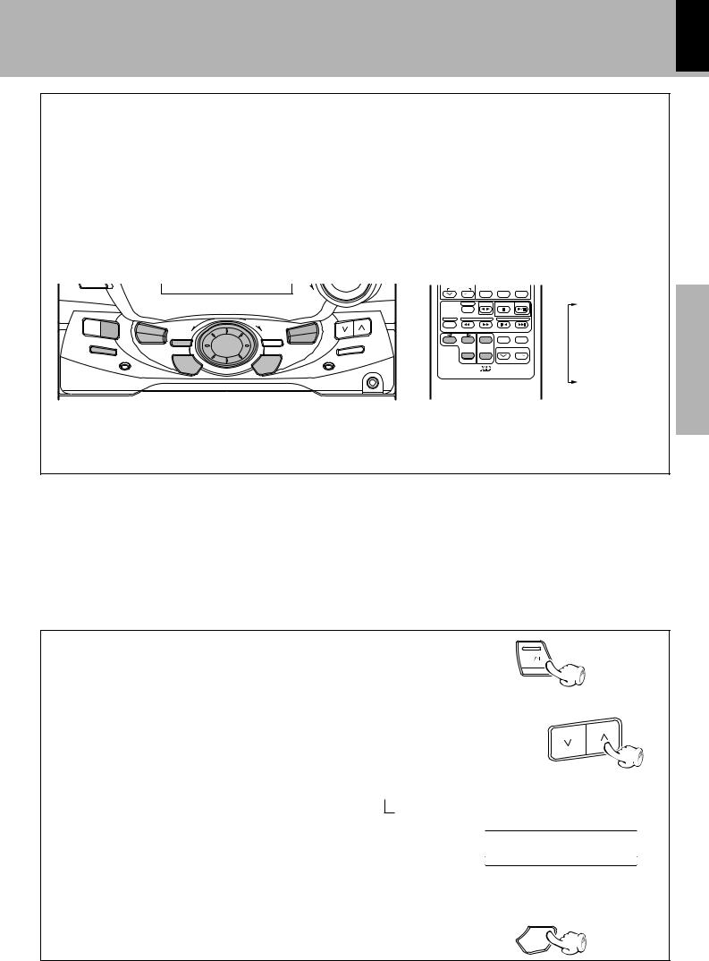
Remote sensor |
|
6m |
|
30˚ |
30˚ |
Operating range (approx.)
|
1. The provided batteries are intended for use in operation checking, and their service life may be short. |
Notes |
2. When the remote controllable distance becomes short, replace both of the batteries with new ones. |
3. If direct sunlight or the light of a highfrequency fluorescent lamp (inverter type, etc.) is incident to the remote sensor, malfunction may occur. |
|
|
In such a case, change the installation position to avoid malfunction. |
Application section
Knowledge sections
CHANNEL SPACE setting
(Except for the U.S.A., Canada, U.K., Europe, Russia and Australia)
The space between radio channels has been set to the one that prevails in the area to which the system is shipped. However, if the current channel space setting does not match the setting in the area where the system is to be used, for instance when you move from area 1 or area 2 shown in the following table or vice versa, proper reception of AM/FM (MW/FM) broadcasts cannot be expected. In this case, change the channel space setting in accordance with your area by referring to the following table.
|
Area |
CHANNEL |
||
|
SPACE freq. |
|||
|
|
|||
|
|
|
||
1 |
U.S.A., Canada and South |
FM : 100 kHz |
||
American countries |
AM : |
10 kHz |
||
|
||||
|
|
|
|
|
2 |
Other countries |
FM : |
50 kHz |
|
AM : |
9 kHz |
|||
|
|
|||
1Turn power off.
ON/STANDBY
2Select the channel space. TUNING
Each press switches the space frequency alternately. |
1 “FM100/AM10 kHz” ....... STEP, |
2 “FM 50 /AM 9 kHz” ....... STEP, |
÷The “AM” display is variable depending on the model (country or area), and “MW” may be displayed in some areas.

 FM10 0/ AM 1 0

 FM 5 0/ AM
 9
9
3Establish the selection.
ENTER
17
XD-951/A900/A700 (En)
MULTI CONTROL jog dial
The MULTI CONTROL jog dial allows you to set (or enter) a variety of functions with an easy operation.
The mode for setting (using) MULTI CONTROL is initiated when any of the CD PGM, DUBBING, SOUND, DISPLAY, TIMER, LISTEN MODE and MODE/DEMO keys is pressed.
In the setting mode, select the operation mode with the MULTI CONTROL jog dial and press the SET and/or ENTER key(s) to set, establish, enter or execute the function.
(The ENTER key is always pressed at the end.)
ON/STANDBY |
|
|
|
DOWN |
|
|
|
MULTI |
TUNING |
|
|
|
|
|
EX. |
|
|
CONTROL |
|
|
|
|
|
|
BASS SOUND |
TIMER |
LISTEN |
|
CD PGM |
|
MODE |
MODE |
SRS 3D |
DUBBING |
|
/DEMO |
|
|
|
DISPLAY |
|
|
|
|
|
|
|
BAND |
|
INPUT |
|
SET |
ENTER |
AUTO |
|
|
|
||
|
|
|
|
PHONES |
With the remote control unit, pressing the MENU key makes it possible to select the same items as those available on the main unit using the MENU (up#/down@) keys.
SURROUND |
TA/NEWS/INFO.RDS DISP. PTY |
A/B |
TAPE |
CD |
CD PGM |
|
BAND TUNING |
P.CALL |
DUBBING |
||
|
SET |
MUTE INPUT |
SOUND |
|
MENU |
ENTER |
VOLUME |
DISPLAY |
|
|
TIMER |
|||
|
|
|
||
REMOTE CONTROL UNIT RC-951R |
LISTEN MODE |
|||
MODE |
||||
|
|
|
||
÷During the setting of an item (while the guideline is blinking), other keys are defeated except for the basic control keys such as the VOLUME CONTROL and ON/STANDBY keys.
÷To cancel the mode for setting (using) MULTI CONTROL, read the description of each item in this manual.
section Preparation
For Russia
Reception mode switching of FM broadcast |
1Turn power off. |
|
When you want to receive an FM broadcast in PILOT TONE mode, |
|
|
|
|
|
|
|
|
changing the setting as follows. |
ON/STANDBY |
|
|
2Press the TUNING ( ) key. |
|
TUNING
section Application
Each press switches the reception mode alternately.
 1 POLAR system
2 PILOT TONE system
POLA R
PILO T
3Establish the selection.
ENTER
sections Knowledge
18 Let’s put out some sound
Preparation section
Basic section
Application section
Knowledge sections
XD-951/A900/A700 (En)
Basic use method
Adjust the subwoofer volume level.
Bass compensation
1 |
|
|
3 |
EX.BASS |
|
|
|
|
2 |
|
|
|
|
|
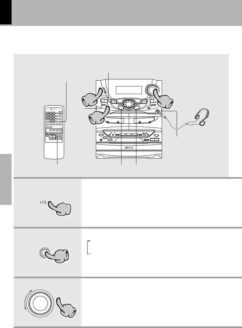
Listening through headphones |
|
|
|
Insert the headphone plug into |
|
|
|
the PHONES jack. |
Muting the sound temporarily |
SET |
ENTER |
÷The sounds from all speakers are |
cut off. |
 1
1
ON/STANDBY
INPUT
2
UP |
VOLUME |
|
CONTROL |
DOWN |
3 |
1. Switching the power ON (OFF)
The power can also be turned ON by pressing the play key of the CD player, the play key of the cassette deck or the BAND key of the tuner.
When the ON/STANDBY key is pressed while the power is ON, the power will be switched OFF.
÷The display part becomes dark when the power is switched OFF. (DIMMER function)
2. Selecting the desired output
1TUNER (Radio) |
§ |
2CD |
) |
3TAPE |
™ |
4AUX (External input) !
÷When you select the AUX input, be also sure to read the instruction manual of the component connected to the AUX input jacks.
(AUX INPUT LEVEL adjustment u)
÷When CD or TAPE is selected, playback will start when a disc or a tape already has been inserted into disc tray or deck B.
3. Volume adjustment
÷Quick turning produces a larger change amount. (AI VOLUME control function)
÷The display shows a reference value.
Muting the sound temporarily (Remote control unit only)
Blinks
MUTE
 CD 0 1 1 2 3
Remote control unit
÷Press again to resume the original volume.
÷The sound muting is also canceled when the volume is controlled.
Bass compensation (EX.BASS)
EX.
BASS
÷Each press switches EX.BASS on and off alternately.
÷The EX.BASS is switched off automatically during recording.
STANDBY mode of ON/STANDBY ( 

 ) key
) key
When the display shows the time or “- - : - -”, a small amount of current is supplied to the unit to back up the internal memory. This status is referred to as the STANDBY mode, and the unit in the STANDBY mode can be turned ON from the remote control unit.
When CD has been selected.
CD 0 1 0 0 0
 1
1  2
2  3
3
Volume display
VO L 5 7
 1
1  2
2  3
3
Let's put out some sound 19
XD-951/A900/A700 (En)
Sub woofer level adjustment
(Except for the XD-A700)
Adjust the sub woofer level according to the category of music and your liking.
1 Press the MODE/DEMO key. |
|
|||
|
|
MODE |
|
|
|
|
/DEMO |
|
|
2 Select “S.W.” and press the SET key. |
|
|||
MULTI |
|
SRS LEVEL |
|
|
CONTROL |
|
|
||
|
|
(Only when SRS 3D is ON) |
|
|
|
|
S.W. |
|
|
|
|
L/R BALANCE |
|
|
SET |
|
|
Preparation |
|
|
|
s W |
||
Go to step 3 within 15 sec. |
sUB LE VE L |
|||
|
|
|||
|
|
section |
||
3 Select the desired level and press the ENTER key. |
||||
|
||||
MULTI |
OFF |
|
||
CONTROL |
|
|||
|
LEVEL 1 |
|
||
|
LEVEL 2 |
|
||
|
LEVEL 3 |
|
||
|
LEVEL 4 |
|
||
ENTER |
LEVEL 5 |
|
||
AUTO POWER SAVE function |
section Basic |
|||
|
||||
When the power is ON and neither recording nor playback is executed for 30 minutes or more, the power is switched off automatically by this function. This function can be made active or not active by the following operation.
1 Press the TIMER key.
|
TIMER |
Application |
2 Select “AUTO POWER SAVE” and press the SET key. |
|
|
CONTROL |
SLEEP |
|
MULTI |
O.T.T. |
section |
|
||
|
TIME SET |
|
|
PROG. ON/OFF |
|
|
PROG. 1 |
|
SET |
PROG. 2 |
|
|
AUTO POWER SAVE |
|
3 Select “ON” or “OFF” and press the ENTER key.
|
|
AUTO TP OW E R |
Knowledge |
|
MULTI |
| Scrolled display |
|
|
CONTROL |
|
|
|
|
|
|
|
|
(AUTO POWER SAVE) |
sections |
ENTER |
|
used. |
|
|
|
ON ..... Auto power save is used. |
|
|
|
OFF .... Auto power save is not |
|
|
|
RETURN |
|
÷This function is not available when the AUX input is selected. When the TUNER input is selected, it is available only when the volume is set to 0.
20 |
Let's put out some sound |
|
|
|
XD-951/A900/A700 (En) |
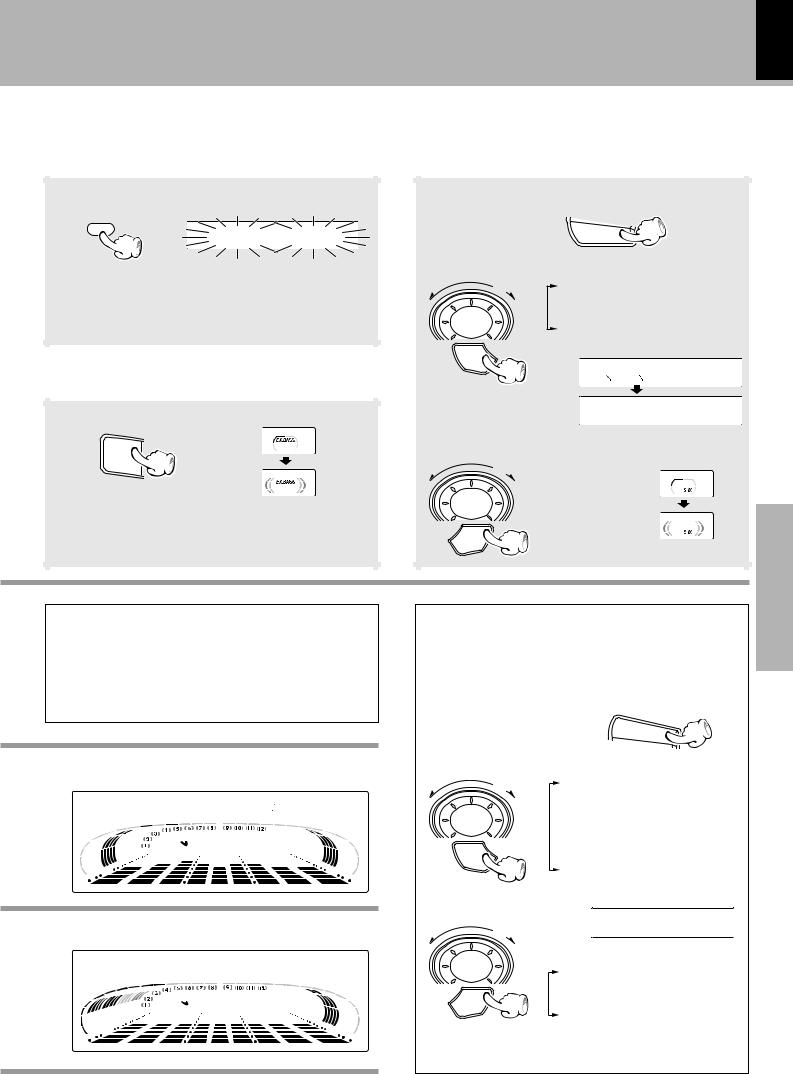
Playback of CD
If a disc has already been loaded in the CD player and the power is OFF, simply pressing the CD play key turns power automatically ON and starts playback.
Preparation section
Basic section
Application section
Knowledge sections
Playback from desired track |
Skipping tracks |
TIME
To stop Playback


 1
1


 2
2 
High-speed search in forward and |
Playback form desired track |
reverse directions |
|
1. Load a disc.
0
The label must be on top.
1 Open the tray.
1 2 Place a disc.
3 Close the tray.
The tray opens when the key is pressed |
Disc played first when the 6key is pressed. |
and closes when the key is pressed again. |
2. Start playback.
^
2
÷After a few seconds, play starts from track No.1.
Time display on the CD player
Each press of the TIME key of the remote control unit switches the displayed time information.
÷Only the time information related to the track being played can be displayed in the program, CD EDIT and random modes.
1 |
|
1:2 3 |
2 |
- 2:3 7 |
|
3 |
2 |
3:4 5 |
4 - 3 |
6:1 5 |
|
Elapsed time of track being played Remaining time of track being played Elapsed time of disc (TOTAL lights up) Remaining time of disc (TOTAL lights up)
Let's put out some sound |
21 |
|
|
XD-951/A900/A700 (En) |
|
Skipping tracks
MULTI
CONTROL
To skip backward |
To skip forward |
÷The tracks in the direction the dial is rotated are skipped, and the selected track will be played from the beginning.
÷When the jog dial is rotated a little in the direction of counterclockwise once during playback, the track being played will be played from the beginning.
÷The CD tracks can also be skipped using the 4or ¢key of the remote control unit and main unit.
Playback from desired track
Select the disc. |
|
Select the desired track No. |
||
DISC 1 |
Main |
1 |
2 |
3 |
|
unit |
|||
|
|
|
|
|
DISC 2 |
|
4 |
5 |
6 |
|
|
|||
|
DISC 3 |
|
|
|
|
|
7 |
8 |
9 |
|
|
|
0 |
+10 |
|
DISC SKIP |
|
|
|
Remote control unit
Press the numeric keys as shown below....
To enter track No. 23 : 003
To select track No. 40 : 0000)
High-speed search in forward and reverse directions
Backward search |
TUNING |
Forward search |
Remote control unit
÷Playback starts from the position where the key is released.
To pause playback
6
÷Each press pauses and plays the CD alternately.
To stop playback
7
÷Do not touch the played side of disc.
÷Rotate the tray with the DISC SKIP key to insert the third disc.
÷The tray of the disc to be played should come to the left position when the unit is seen from the front.
The selected disc is indicated.
CD |
0 1 |
0 0 0 |
|||||
|
|
1 |
2 |
3 |
|
|
|
|
|
||||||
|
|
|
|
||||
|
|
|
|
|
|||
|
|
|
|
|
|
||
Lights when a disc is inserted at |
|
|
|||||
the time of playback. |
|
|
The recorded track No. are shown. |
||||
|
|
|
|
|
|
||
section Preparation
section Basic
section Application
sections Knowledge
 Loading...