


COMPACT HI-FI SYSTEM
XD-SERIES
XD-652
XD-852
XD-702/ XD-752/ XD-772S
INSTRUCTION MANUAL
KENWOOD CORPORATION
This instruction manual is used to describe multiple models listed above. |
|
Model availability and features (functions) may differ depending on the country |
|
and sales area. |
\s |
COMPACT
DIGITAL AUDIO
TEXT
B60-4246-00 00 MA (Y,M,X,T,Q,E2) MC 9811
2 Before applying power
XD-SERIES (EN/M,T)
 Caution : Read this page carefully to ensure safe operation.
Units are designed for operation as follows.
U.S.A. and Canada ............................................ |
AC 120 V only |
Australia ............................................................. |
AC 240 V only |
Europe and U.K. ................................................. |
AC 230 V only |
China and Russia .............................................. |
AC 220 V only |
*Other countries ........... |
AC 110-120 / 220-240 V switchable |
For the United Kingdom
Preparation section
Factory fitted moulded mains plug
1.The mains plug contains a fuse. For replacement, use only a 13-Amp ASTA-approved (BS1362) fuse.
2.The fuse cover must be refitted when replacing the fuse in the moulded plug.
3.Do not cut off the mains plug from this equipment. If the plug fitted is not suitable for the power points in your home or the cable is too short to reach a power point, then obtain an appropriate safety approved extension lead or adapter, or consult your dealer.
If nonetheless the mains plug is cut off, remove the fuse and dispose of the plug immediately, to avoid a possible shock hazard by inadvertent connection to the mains supply.
IMPORTANT: The wires in the mains lead are coloured in accordance with the following code: Blue : Neutral
Brown : Live
Do not connect those leads to the earth terminal of a threepin plug.
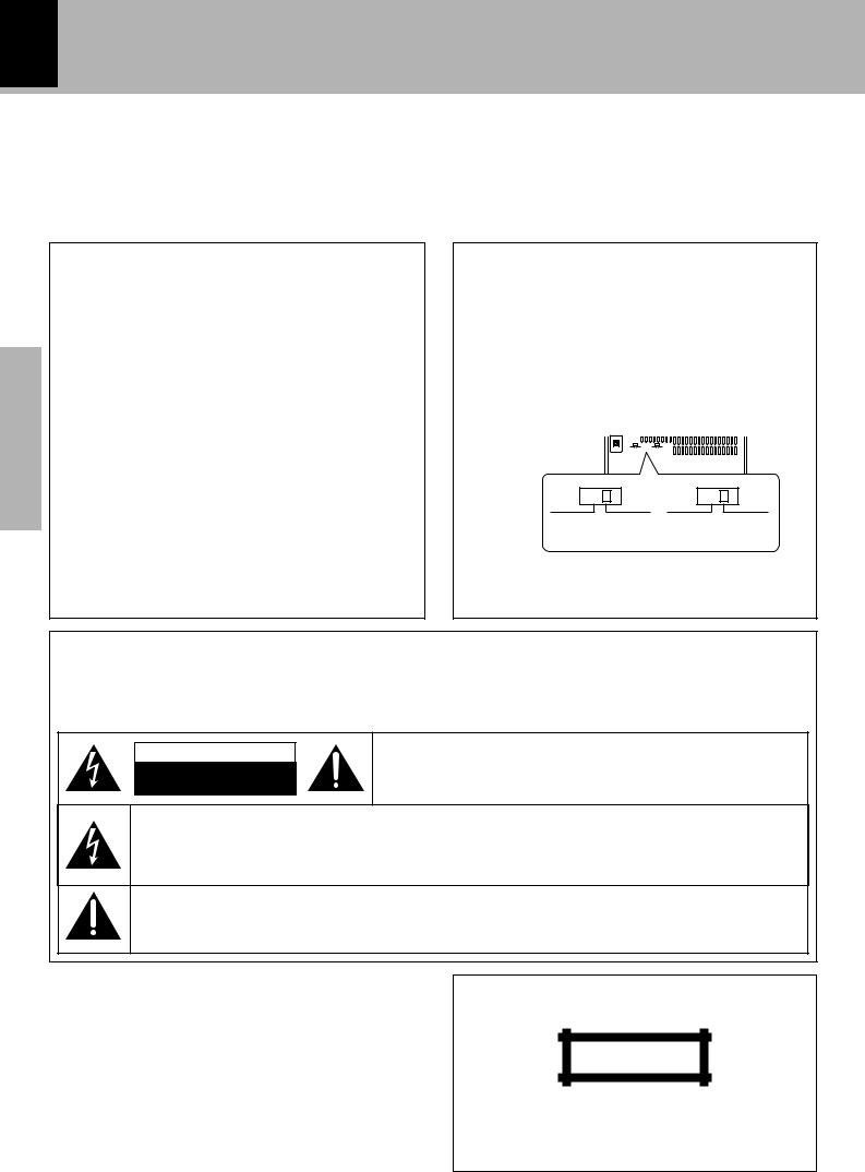
*AC voltage selection
The AC voltage selector switch on the rear panel is set to the voltage that prevails in the area to which the unit is shipped. Before connecting the power cord to your AC outlet, make sure that the setting position of this switch matches your line voltage. If not, it must be set to your voltage in accordance with the following direction.
AC voltage selector switch
Move switch lever to match your line voltage with a small screwdriver or other pointed tool.
MD/DVD INPUT
DIGITAL OUT
OPTICAL
AC 110- |
AC 220- |
AC 110- |
AC 220- |
120V~ |
240V~ |
120V~ |
240V~ |
Note:
Our warranty does not cover damage caused by excessive line voltage due to improper setting of the AC voltage selector switch.
Safety precautions
WARNING : TO PREVENT FIRE OR ELECTRIC SHOCK, DO NOT EXPOSE THIS APPLIANCE TO RAIN OR MOISTURE.
CAUTION
RISK OF ELECTRIC SHOCK
DO NOT OPEN
CAUTION: TO REDUCE THE RISK OF ELECTRIC SHOCK, DO NOT REMOVE COVER (OR BACK). NO USER-SERVICEABLE PARTS INSIDE. REFER SERVICINGTO QUALIFIED SERVICE PERSONNEL.
THE LIGHTNING FLASH WITH ARROWHEAD SYMBOL, WITHIN AN EQUILATERAL TRIANGLE, IS INTENDEDTO ALERTTHE USERTOTHE PRESENCE OF UNINSULATED “DANGEROUS VOLTAGE” WITHIN THE PRODUCT’S ENCLOSURE THAT MAY BE OF SUFFICIENT MAGNITUDE TO CONSTITUTE A RISK OF ELECTRIC SHOCK TO PERSONS.
THE EXCLAMATION POINT WITHIN AN EQUILATERAL TRIANGLE IS INTENDED TO ALERT THE USER TO THE PRESENCE OF IMPORTANT OPERATING AND MAINTENANCE (SERVICING) INSTRUCTIONS IN THE LITERATURE ACCOMPANYING THE APPLIANCE.
The marking of products using lasers
(Except for some areas)
CLASS 1
LASER PRODUCT
The marking is located on the rear panel and says that the component uses laser beams that have been classified as Class 1. It means that the unit is utilizing laser beams that are of a weaker class. There is no danger of hazardous radiation outside the unit.
Before applying power 3
XD-SERIES (EN/M,T)
Contents
Caution : Read the pages marked  carefully to ensure safe operation.
Preparation section |
|
|
Before applying power .............................. |
2 |
|
Safety precautions...................................... |
|
2 |
IMPORTANT SAFEGUARDS........................ |
4 |
|
Special features ............................................... |
|
6 |
System connection........................................... |
|
7 |
Accessories ....................................................................... |
|
7 |
Connection of the system accessories ......................... |
7 |
|
Connection of the surround speakers |
|
|
(XD-6...series, XD-8...series) ..................................... |
10 |
|
Connection with other components (optional or com- |
||
mercially-available equipment) ................................... |
11 |
|
Controls and indicators |
................................. |
13 |
Display .............................................................................. |
|
13 |
Main unit ........................................................................... |
|
14 |
Remote control unit (XD-7... |
series).............................. |
16 |
Remote control unit (XD-6... |
series, XD-8...series) .... |
17 |
Operation of jog dials |
|
|
(XD-7...series) .............................................. |
|
18 |
Operation of jog dials |
|
|
(XD-6...series, XD-8... |
series) ..................... |
19 |
Operation of remote control unit .................. |
20 |
|
CHANNEL SPACE setting ................................................ |
|
20 |
Handling of discs and tapes .......................... |
21 |
|
Basic section |
|
|
Let's put out some sound................................ |
22 |
|
Basic use method............................................................ |
|
22 |
Playback of CD ................................................................ |
|
24 |
Playback of tape.............................................................. |
|
26 |
Searching for the desired music program (DPSS) |
|
|
(XD-7...series, XD-8...series only) ........................... |
29 |
|
Receiving broadcast station .......................................... |
30 |
|
Let's record ...................................................... |
|
32 |
Recording on TAPE ......................................................... |
|
32 |
Copying tape (Tape dubbing) ......................................... |
35 |
|
Application section
Playback of CD................................................ |
36 |
Listening in the desired sequence |
|
(program playback) ................................................... |
36 |
Repeated playback ......................................................... |
38 |
Random playback ............................................................ |
40 |
R.D.S. (Radio Data System) |
|
(For U.K., Europe and Russia) ................... |
41 |
Preparation |
at any time (EON)............................................................. |
44 |
|
Searching for a desired program type |
|
|
(PTY search) ................................................................ |
42 |
|
To be able to listen to the desired information |
|
|
Convenient CD recording ............................... |
46 |
section |
|
Selection of the recording type |
46 |
||
|
|||
Recording only desired titles |
|
|
|
(CD ONE TRACK RECORDING) ................................. |
47 |
|
|
Recording of an entire CD |
|
|
|
(CD DIRECT RECORDING) .......................................... |
48 |
|
|
Recording the programmed titles |
|
|
|
(CD PROGRAM RECORDING) .................................... |
49 |
|
Effective sound adjustment .......................... |
|
50 |
|
Basic |
||
|
Balance adjustment......................................................... |
|
|
50 |
||
|
Input level adjustment .................................................... |
|
|
51 |
section |
|
|
Listening to music with desired tone and sound field |
|||||
|
....................................................................................... |
|
|
52 |
|
|
|
Creation and memorizing of an equalizer pattern ..... |
54 |
|
|
||
|
Surround function (XD-6... |
series, XD-8... |
series) ............ |
55 |
|
|
|
Surround setting (XD-6... |
series, XD-8... |
series) ............. |
56 |
|
|
Clock adjustment............................................. |
|
|
58 |
|
|
|
|
|
|
|
|||
Timer operation............................................... |
|
|
59 |
|
|
|
|
Sleep timer ........................................................................ |
|
|
59 |
Application |
|
|
Operate easy To use Timer (O.T.T.) |
|
60 |
|||
|
|
|
||||
|
Timer programming.......................................................... |
|
|
61 |
|
|
|
|
|
|
|
|
section |
|
Knowledge section |
|
|
|||
|
|
|
|
|||
|
|
|
|
|
|
|
Important Items ................................................ |
|
|
64 |
|
|
|
|
....................................................................Maintenance |
|
|
64 |
|
|
|
.........................................................................Reference |
|
|
64 |
|
|
In case of difficulty ........................................ |
|
|
65 |
|
Knowledge |
|
Specifications (XD-7 |
series) |
|
69 |
|
||
|
|
|
||||
Specifications (XD-6... |
series, XD-8...series) |
70 |
|
|
||
|
....................................................................... |
|
|
|
section |
|
|
|
|
|
|
|
|
|
|
|
|
|
|
|
4 IMPORTANT SAFEGUARDS
Preparation section
 Caution :Read this page carefully to ensure safe operation.
Please read all of the safety and operating instructions before operating this appliance. Adhere to all warnings on the appliance and in the instruction manual. Follow all the safety and operating instructions. These safety and operating instructions should be retained for future reference.
1.Power sources – The appliance should be connected to a power supply only of the type described in the instruction manual or as marked on the appliance. If you are not sure of the type of power supply to your home, consult your appliance dealer or local power company. For appliances intended to operate from battery power, or other sources, refer to the instruction manual.
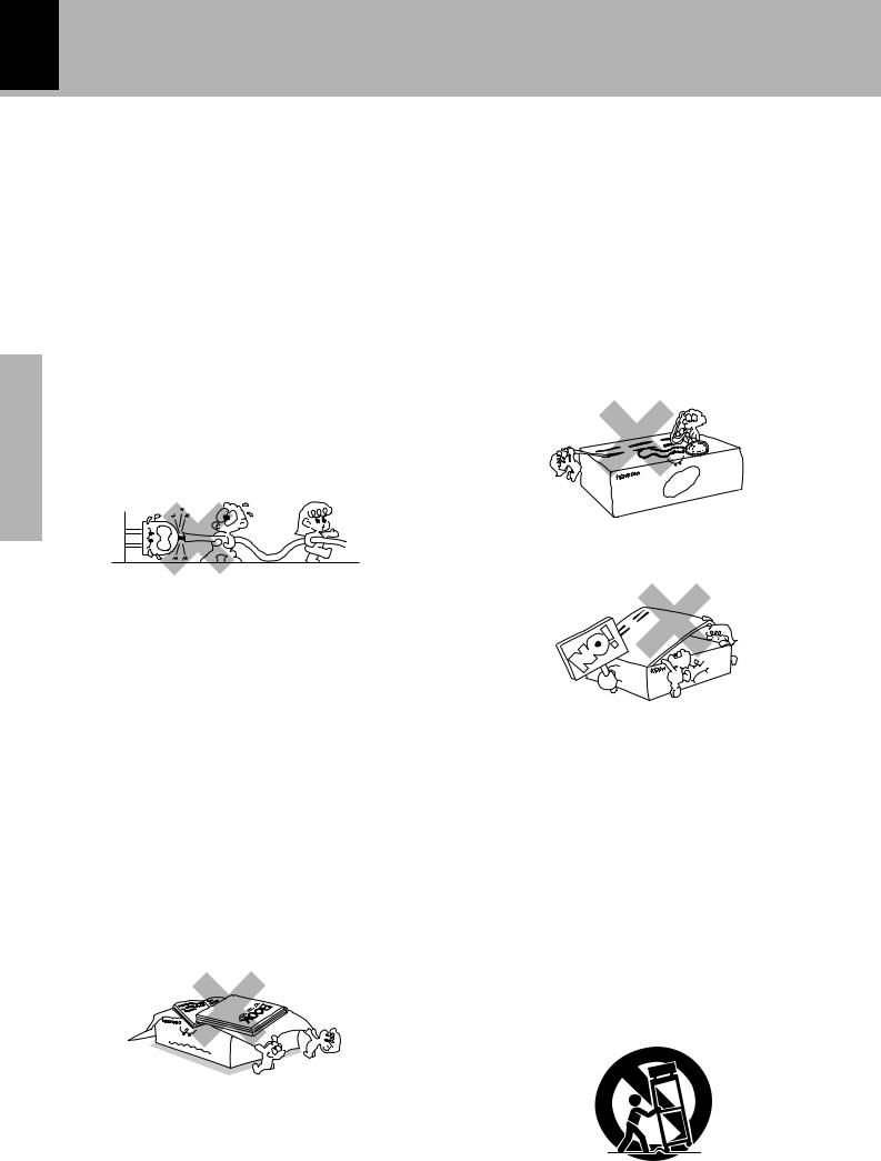
2.Power-cord protection – Power-supply cords should be routed so that they are not likely to be walked on or pinched by items placed upon or against them, pay particular attention to cords at plugs, convenience receptacles, and the point where they exit from the appliance.
Never pull or stretch the cord.
3. CAUTION – Polarization – This appliance may
be equipped with a polarized alternating-current line plug (a plug having one blade wider than the other). This plug will fit into the power outlet only one way. This is a safety feature. If you are unable to insert the plug fully into the outlet, try reversing the plug. If the plug should still fail to fit, contact your electrician to replace your obsolete outlet. Do not defeat the safety purpose of the polarized plug.
4.Ventilation – Slots and openings in the cabinet are provided for ventilation and to ensure reliable operation of the appliance and to protect it from overheating, and these openings must not be blocked or covered. The appliance should be situated so that its location or position does not interfere with its proper ventilation.
To maintain good ventilation, do not put records or a table-cloth on the appliance. Place the appliance at least 10 cm away from the walls.
Do not use the appliance on a bed, sofa, rug or similar surface that may block the ventilation openings. This appliance should not be placed in a built-in installation such as a bookcase or rack unless proper ventilation is provided or the manufacturer’s instructions have been adhered to.
5.Water and moisture – The appliance should not be used near water - for example, near a bathtub, washbowl, kitchen sink, laundry tub, in a wet basement, or near a swimming pool, etc.
XD-SERIES (EN/M,T)
6.Temperature – The appliance may not function properly if used at extremely low, or freezing temperatures. The ideal ambient temperature is above +5°C (41°F).
7.Heat – The appliance should be situated away from heat sources such as radiators, heat registers, stoves, or other appliances (including amplifiers) that produce heat.
8.Electric shock – Care should be taken so that objects do not fall and liquid is not spilled into the enclosure through openings. If a metal objects, such as a hair pin or a needle, comes into contact with the inside of this appliance, a dangerous electric shock may result. For families with children, never permit children to put anything, especially metal, inside this appliance.
9.Enclosure removal – Never remove the enclosure. If the internal parts are touched accidentally, a serious electric shock might occur.
10.Magnetic fields – Keep the appliance away from sources of magnetic fields such as TV sets, speaker systems, radios, motorized toys or magnetized objects.
11.Cleaning – Unplug this appliance from the wall outlet before cleaning. Do not use volatile solvents such as alcohol, paint thinner, gasoline, or benzine, etc. to clean the cabinet. Use a clean dry cloth.
12.Accessories – Do not place this appliance on an unstable cart, stand, tripod, bracket, or table. The appliance may fall, causing serious injury to a child or adult, and serious damage to the appliance. Use only with a cart, stand, tripod, bracket, or table recommended by the manufacturer, or sold with the appliance. Any mounting of the appliance should followthe manufacturer’s instructions, and should use a mounting accessory recommended by the manufacturer. An appliance and cart combinationshouldbemovedwithcare.Quickstops,excessive force, and uneven surfaces may cause the appliance and cart combination to overturn.
13.Lightning – For added protection for this appliance during a lightning storm, or when it is left unattended and unused for long periods of time, unplug it from the wall outlet and disconnect the antenna or cable system. This will prevent damage to the appliance due to lightning and power-line surges.
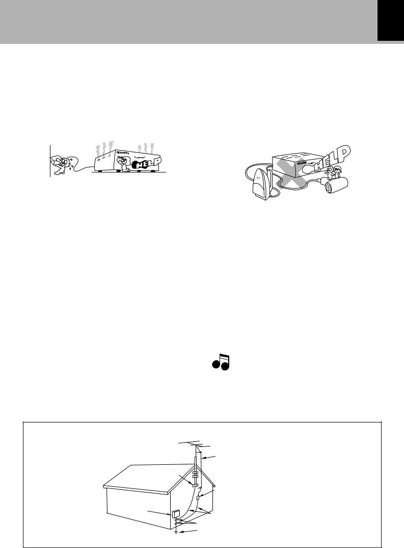
14.Abnormal smell – If an abnormal smell or smoke is detected, immediately turn the power OFF and unplug the appliance from the wall outlet. Contact your dealer or nearest service center.
POWER OFF!
15.Damage requiring service – The appliance should be serviced by qualified service personnel when:
A.The power-supply cord or the plug has been damaged.
B.Objects have fallen, or liquid has been spilled into the appliance.
C.The appliance has been exposed to rain or water.
D.The appliance does not appear to operate normally by following the instruction manual. Adjust only those controls that are covered by the instruction manual as an improper adjustment of other controls may result in damage and will often require extensive work by a qualified technician to restore the appliance to its normal operation.
E.The appliance has been dropped, or the enclosure damaged.
F.The appliance exhibits a marked change in performance.
16.Servicing – The user should not attempt to service the appliance beyond that described in the instruction manual. All other servicing should be referred to qualified service personnel.
17.Outdoor antenna grounding – If an outside antenna is connected to the appliance, be sure the antenna system is grounded so as to provide some protection against voltage surges and built up static charges. Article 810 of the National Electrical Code ANSI/NFPA 70, provides information with respect to proper grounding of the mast and supporting structure, grounding of the lead-in wire to an antenna discharge unit, size of grounding conductors, location of antenna discharge unit, connection to grounding electrodes, and requirements for the grounding electrode. See Figure.
IMPORTANT SAFEGUARDS 5
XD-SERIES (EN/M,T)
18.Power lines – An outside antenna system should not be located in the vicinity of overhead power lines or other electric light or power circuits, or where it can fall into such power lines or circuits. When installing an outside antenna system, extreme care should be taken to keep from touching such power lines or circuits as contact with them might be fatal.
19.AC outlets – Do not connect other audio equipment with a power consumption larger than that specified to the AC outlet on the rear panel. Never connect other electrical appliances, such as an iron or toaster, to it to prevent fire or electric shock.
20. Overloading – Do not overload wall outlets, extension cords, |
Preparation |
|
or integral convenience receptacles as this can result in a risk |
section |
|
of fire or electric shock. |
||
|
||
21. Attachment – Do not use attachments not recommended by |
|
|
the appliance manufacturer as they may cause hazards. |
|
|
22. Replacement parts – When replacement parts are required, |
|
|
be sure the service technician has used replacement parts |
|
|
specified by the manufacturer or have the same characteristics |
|
|
as the original parts. Unauthorized substitutions may result in |
|
|
fire, electric shock, or other hazards. |
|
|
23. Safety check – Upon completion of any service or repairs to |
|
|
this appliance, ask the service technician to perform safety |
|
|
checks to determine that the appliance is in proper operating |
|
|
condition. |
|
Notes
1.Item 3 is not required except for grounded or polarized equipment.
2.Item 17 and 18 are not required except for units provided with antenna terminals.
3.Item 17 complies with UL in the U.S.A.
EXAMPLE OF ANTENNA GROUNDING AS PER NATIONAL ELECTRICAL CODE
GROUND
CLAMPS
ELECTRIC
SERVICE
EQUIPMENT
NEC – NATIONAL ELECTRICAL CODE
ANTENNA LEAD IN WIRE
ANTENNA DISCHARGE UNIT (NEC SECTION 810-20)
GROUNDING CONDUCTORS (NEC SECTION 810-21) GROUND CLAMP
POWER SERVICE GROUNDING ELECTRODE SYSTEM (NEC ART 250, PART H)

6 Special features
XD-SERIES (EN/M,T)
Simplified operations using large-sized, Twin Jog Dials
Multi-control jog dial (Right dial: For use in selecting a function)
This dial allows you to set the CD program and timer-related operations while observing the operating conditions shown by the display and icons.
Sound control jog dial (Left dial: For use in selecting the tone and sound field)
This dial allows you to reproduce realistic audio by setting and registering desired equalizer patterns as well as selecting the preset equalizer patterns.
Preparation section
3D large-sized color display panel
The large sound level meter represents the movement in music with brilliant colors to offer the joy of viewing the music at the same time as listening.
Dolby Pro Logic Surround, Dolby 3 Stereo Surround (XD-6...series, XD-8...series only)
The Dolby Pro Logic and Dolby 3 Stereo are top-level surround modes that can reproduce the world of 3- dimensional audio.
Dolby Virtual Surround (XD-6...series, XD-8...series only)
The Dolby Virtual Surround function offers a simulated surround effect using only the left and right front speakers.
Built in super woofer (XD-7...series only)
A super woofer is built into the 3-way speaker system, allowing reproduction of heavy bass sound with incomparable powerfulness with ordinary system speaker systems.
CD text information display (CD TEXT compatibility)
The text information (disc title and track titles) recorded in CDs can be displayed.
Demonstration
When the power supply is restored after a power failure or the power cord is unplugged and plugged in again during use, this unit automatically starts the demonstration function (display only). During the demonstration, the display changes in sequence but the audio does not change.
To cancel : |
To switch over the demonstration : |
PresstheDISPLAY/DEMOkeyduringdemon- |
Turn the unit OFF (STANDBY mode) and press the |
stration to stop it. |
DISPLAY/DEMO key. |
|
Each press of the key switches the demonstration |
DISPLAY /DEMO
as shown below.
 1 ”Demo on“ (Demonstration executed)
  2 “Demo off” (Demonstration canceled)
System connection
7
XD-SERIES (EN/M,T)
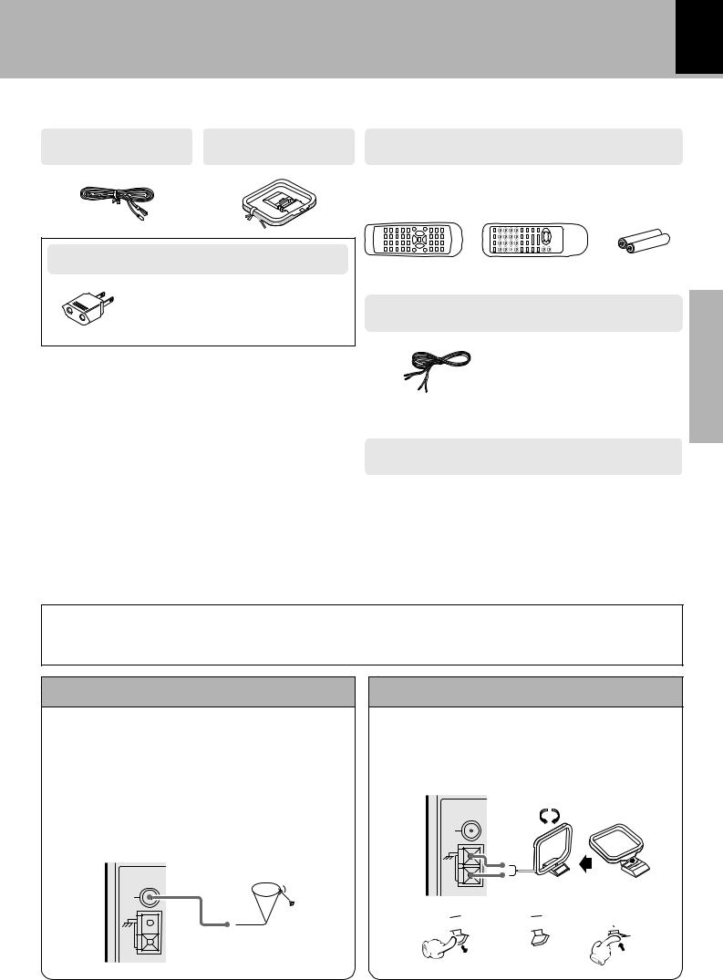
Accessories
FM indoor antenna |
AM loop antenna |
|
Remote control unit (1) |
(1) |
(1) |
|
Batteries (R6/AA) (2) |
|
XD-6... |
series |
|
|
XD-8... |
series |
XD-7...series |
AC plug adaptor (1)
Use to adapt the plug on the power cord to the shape of the wall outlet.
(Accessory only for regions where use is necesary.)
Unpacking
Unpack the unit carefully and make sure that all accessories are put aside so they will not be lost.
Examine the unit for any possibility of shipping damage. If your unit is damaged or fails to operate, notify your dealer immediately. If your unit was shipped to you directly, notify the shipping company without delay. Only the consignee (the person or company receiving the unit) can file a claim against the carrier for shipping damage.
We recommend that you retain the original carton and packing materials for use should you transport or ship the unit in the future.
Keep this manual handy for future reference.
Speaker cords
XD-6...series, XD-8...series (2)
XD-7...series (4)
Provided in the speaker package
Surround speaker system (Except for XD-7...series)
Surround speaker (2) |
Center speaker (1) |
Speaker cord (2) |
Speaker cord (1) |
Speaker stabilizer (8) |
Speaker stabilizer (4) |
section Preparation
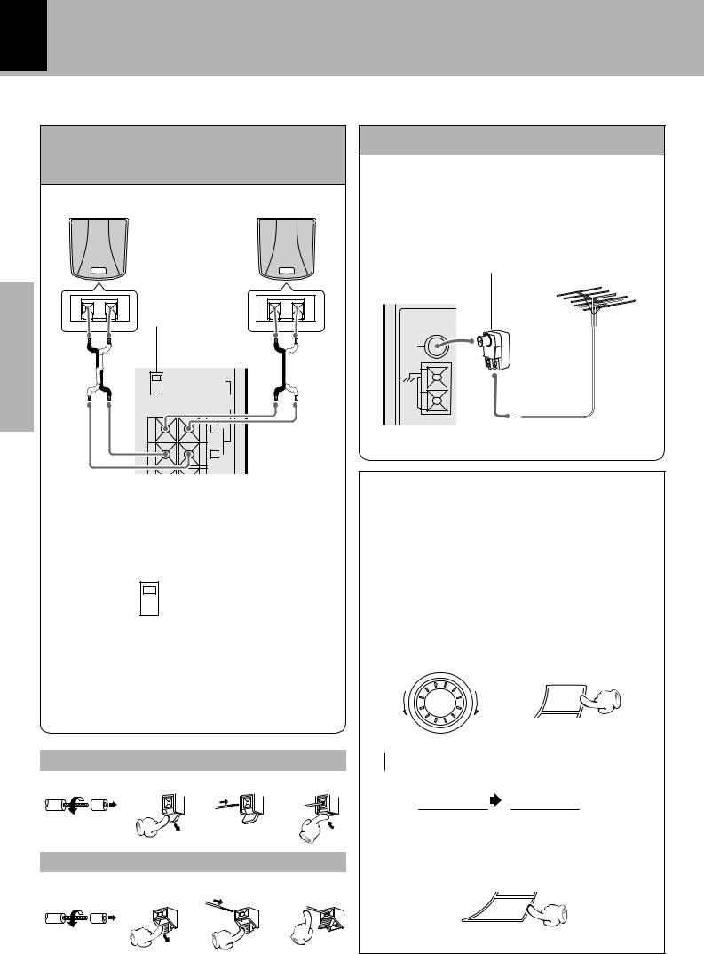
Connection of the system accessories
CAUTION Note on Connection
Connect the components as shown in the diagram.Only plug the power cord into a power outlet once connections are completed. The rear panel configuration is variable depending on the models (countries or area).
FM indoor antenna
The accessory antenna is for temporary indoor use only. For stable signal reception we recommend using an outdoor antenna. Remove the indoor antenna if you connect one outdoors.
1 Connect to the antenna terminal.
2Locate the position providing good reception condition.
3 Fix the antenna.
ANTENNA
FM 75Ω
GND 
AM loop antenna
The supplied antenna is for indoor use. Place it as far as possible from the main system, TV set, speaker cords and power cord, and set it to a direction which provides the best reception.
ANTENNA |
Assemble. |
|
FM 75Ω
GND |
AM
1 


 2
2 
 3
3 
AM
8 |
System connection |
|
|
|
|
|
XD-SERIES (EN/M,T) |
Preparation section
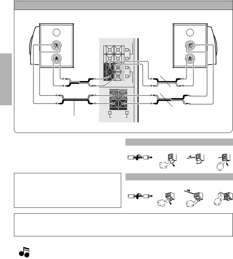
Speakers (XD-7...series)
Speaker (right) |
Speaker (left) |
− |
+ |
− |
+ |
· ª · ª
Speaker cord
5ON |
SURROUND |
|
|
°OFF |
|
|
|
|
SURROUND |
|
|
- |
SPEAKERS |
|
|
+ (8-16Ω) |
|
|
|
|
|
− |
+ |
|
L |
|
|
|
R |
− |
+ |
|
|
||
|
L |
· ª · ª |
|
|
Black |
||
|
|
|
|
|
R |
|
|
SUPER WOOFER |
|
|
|
SPEAKERS(6-16Ω) |
|
|
|
+ |
Red |
Blue |
|
|
|
||
- |
|
Black |
|
R |
L |
|
|
|
|
||
FRONT |
|
|
|
SPEAKERS |
|
|
|
(6-16Ω) |
|
|
|
System Name |
Speaker Model Name |
|
|
XD-702 |
LS-N702 |
|
|
XD-752/ XD-772S |
LS-N752 |
|
|
Speaker and TV installation
If there is a magnet or other device generating magnetic forcenearby,interactionbetweenthemagnetandspeaker maycausecolorblotchingontheTV. Ifthishappens,move the speaker at least 20 cm away from the TV set.
Main Unit
1 |
2 |
3 |
4 |
Twist
Speaker Unit
1 |
2 |
3 |
4 |
Twist
Malfunction of microcomputer
If operation is not possible or erroneous display appears even though all connections have been made properly, reset the microcomputer referring to “In case of difficulty”. ˇ
|
1.Never short-circuit the “+” and “–” speaker cords. |
|
Notes |
2.If the left and right speaker connections or the “+” and “–” polarity are inverted, the sound will |
|
be unnatural with unclear positioning of musical instruments, etc. Be sure to connect them |
||
|
||
|
without mistake. |
|
|
3.Be sure to insert all connection cords securely. If their connections are imperfect, the sound may |
|
|
not be produced or noise may interfere. |
|
|
4.Before plugging or unplugging a connection cord, be sure to unplug the power cord from the wall |
|
|
AC outlet. If connection cords are plugged or unplugged with the power cord left plugged in, |
|
|
malfunction or damage may result. |
|
|
|
System connection 9
XD-SERIES (EN/M,T)
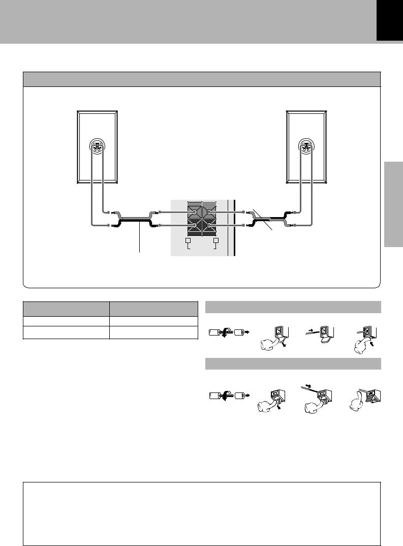
Speakers (XD-6...series, XD-8...series)
Speaker (right) |
Speaker (left) |
|
− + |
· |
ª |
Speaker cord
SURROUND SPEAKERS |
|
|
|
(12-16Ω) |
|
|
|
CENTER SPEAKER(6-16Ω) |
|
|
|
- |
+ |
|
|
|
|
− + |
|
|
L |
|
Preparation |
|
R |
|
|
|
|
|
|
|
· |
ª |
|
+ |
Red |
|
|
|
|
section |
|
- |
Black |
|
|
|
|
||
|
|
|
|
R |
L |
|
|
|
FRONT |
|
|
|
SPEAKERS |
|
|
|
(6-16Ω) |
|
|
System Name |
Speaker Model Name |
|
Main Unit |
|
|
XD-652 |
LS-N472 |
1 |
2 |
3 |
4 |
|
|
|
|
||
XD-852 |
LS-N572 |
|
|
|
|
|
|
Twist |
|
|
|
|
|
|
Speaker Unit |
|
|
|
|
1 |
2 |
3 |
4 |
Twist
Caution regarding placement
Be sure to adhere followings. Or proper ventilation will be blocked causing damage or fire hazard.
÷Do not place any objects impairing heat radiation onto the top of unit.
÷Leave a space around the unit (from the largest outside dimension including projection) equal or greater than, shown
below.
Top panel : 50 cm, Back panel : 10 cm
10 |
System connection |
|
|
|
|
|
XD-SERIES (EN/M,T) |
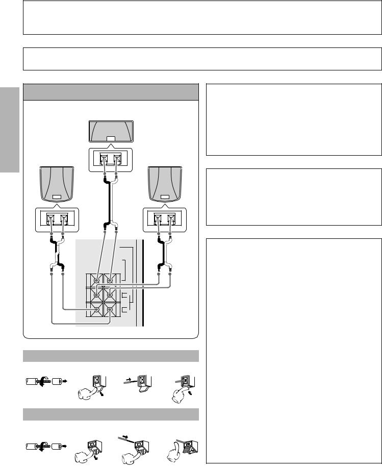
Connection of the surround speakers (XD-6...series, XD-8...series)
CAUTION Note on Connection
Connect the components as shown in the diagram.Only plug the power cord into a power outlet once connections are completed. The rear panel configuration is variable depending on the models (countries or area).
Before connecting the surround speakers system, be also sure to read “Surround function” and “Surround setting”.
TY
Preparation section
Surround speakers system (supplied)
Center speaker
Surround speaker |
− + |
Surround speaker |
|
Recommended speaker installation
It is recommended that the surround speakers are installed straight to the left and right of the listening position or slightly behind, at a height of about 1 meter higher than the listener’s ears. Each surround speaker should be installed so that the longer sides are horizontal.
|
|
|
How to use the speaker stabilizer (cushions) |
· |
ª |
|
When the surround speaker system installation is un- |
|
|
|
|
|
|
|
stable due to the floor condition, apply the provided sta- |
|
|
|
bilizer (cushions) on four positions on the bottom of |
− + |
|
− + |
each speaker. |
|
|
· ªSURROUND SPEAKERS (12-16Ω)
CENTER SPEAKER(6-16Ω)
- +
L 
R 
Main Unit
1 2 3
Twist
Speaker Unit
1 2 3
Twist
· ª
4
4
Hanging on a wall
The speakers can be hung on a wall by using the wall hanging holes on the back of the speaker.When hanging the speakers, select a rigid and hard place on the wall which can withstand the weight of the speakers.
1.Install a screw with sufficient strength on the wall. When screwing in, leave the head and upper stem of the screw projected by 7 to 9 mm from the wall surface.
2.Hang the speaker by inserting the screw into the wall
hanging hole on the upper rear side of the speaker. Check that the speaker are firmly mounted.
÷Before installation, check the wall or ceiling well to confirm that it is strong enough to withstand the weight of the speaker. KENWOOD cannot assume the responsibility against accidents caused by the drop of speaker due to insufficient mounting strength or to any defect in installation.
÷The wall hanging screw is not provided. Please prepare a screw that can assure enough mounting strength according to the material and thickness (structure) of the wall where the speaker is to be hung.
÷If the material or thickness of a wall or ceiling cannot be confirmed, consult a professional specialized in installation.
System connection 11
XD-SERIES (EN/M,T)
Connection with other components(optional or commercially-available equipment)
CAUTION Note on Connection
Connect the components as shown in the diagram.Only plug the power cord into a power outlet once connections are completed. The rear panel configuration is variable depending on the models (countries or area).
MD recorder, DVD player, VCR or analog turntable
MD recorder/VCR |
DVD player/analog turntable (P-110/optional) |
Digital |
Audio |
Audio input |
input |
output |
MD REC OUTPUT |
|
|
|
|
|
L |
|
|
R |
|
|
L |
|
|
R |
|
|
MD/DVD INPUT |
Optical-fiber cable |
DIGITAL OUT |
|
|
|
|
|
|
OPTICAL |
Audio output
÷If an external component such as a DVD player is connected to the MD/DVD INPUT jacks, the MD REC OUTPUT jacks do not output the audio of the external component.
section Preparation
Super woofer
(XD-6...series, XD-8...series only)
Extremely low sound is played back powerfully.
(SW-500/optional)
+ 

-
R |
L |
|
SUPER |
FRONT |
|
WOOFER |
||
SPEAKERS |
||
PRE OUT |
||
(6-16Ω) |
||
|
Power cord
To wall AC outlet
DIGITAL OUT OPTICAL jack
Remove the cap and plug the optical-fiber cable.
Optical-fiber cable |
DIGITAL OUT |
OPTICAL |
|
(Provided with the MD |
Cap |
recorder) |
÷Insert the optical-fiber cable straight into the connector until it clicks.
÷Be sure to attach the protection cap when the connector is not used.
÷Never band or bundle the optical-fiber cable.
In case an associated system component is connected, also read the instruction manual of the Note component.
12
Surround (rear) speakers
(XD-7...series only)
(RS-N852/optional)
System connection
XD-SERIES (EN/M,T)
FM outdoor antenna
Lead the 75Ω coaxial cable connected to the FM outdoor antenna into the room and connect it to the FM
75Ω termimal.
R L
section |
− + |
− + |
|
Surround switch |
|||
Preparation |
|||
· ª |
SURROUND |
||
|
· ª |
||
|
5ON |
SURROUND |
|
|
°OFF |
|
|
|
|
SPEAKERS |
|
-+ (8-16Ω)
L 
R 
In regard to the SURROUND switch
This switch can be used only when the separately sold surround (rear) speakers are connected. When the switch is set to ON, surround playback can be enjoyed. When this switch is set to OFF, normal playback is executed.
5ON SURROUND °OFF
÷Please operate this switch while the power is switched off.
÷We recommend to keep this switch set to OFF when no surround (rear) speakers are connected to obtain a better sound quality.
÷When the switch is set to OFF, no sound will come from the surround (rear) speakers.
Main Unit
1 |
2 |
3 |
4 |
Twist
Speaker Unit
1 |
2 |
3 |
4 |
Twist
Use a commercially-available antenna adapter (a small-sized model).
ANTENNA
FM 75Ω
GND 
AM
Reception mode switching of FM broadcast (For Russia)
When you want to receive an FM broadcast in PILOT TONE mode, changing the setting as follows.
1 Select the TUNER input.
2While holding the SELECT key depressed, turn the SOUND CONTROL jog dial to select the system mode.
ND CONT |
R |
|
U |
O |
|
O |
|
|
S |
|
L |
SELECT
 1 POLAR system
 2 PILOT TONE system
P o l a r |
P i l o t |
3 Establish the selection.
ENTER
Controls and indicators
13
XD-SERIES (EN/M,T)
Display |
The displays given in this manual are approximations only. They may differ from what |
||||||||||||
actually appears on the display. |
|
|
|
|
|
|
|||||||
XD-7...series, XD-8...series |
|
|
|
|
|
|
|
|
|
||||
|
|
|
|
|
|
|
|
|
|||||
|
1 |
2 |
|
3 |
4 5 |
|
|
|
|||||
|
|
|
|
|
|
|
|
|
|
|
|
|
6 |
|
|
|
|
|
|
|
|
|
|
|
|
|
|
|
|
|
|
|
|
|
|
|
|
|
|
|
|
|
|
|
|
|
|
|
|
|
|
|
|
|
|
|
|
|
|
|
|
|
|
|
|
|
|
|
|
|
|
|
|
|
|
|
|
|
|||||
|
|
|
|
|
|
|
|
|
|
|
7 |
||
|
|
|
|
|
|
|
|
|
|
|
|
|
|

 • • • • • • •• •
0 |
|
|
|
9 |
8 |
||
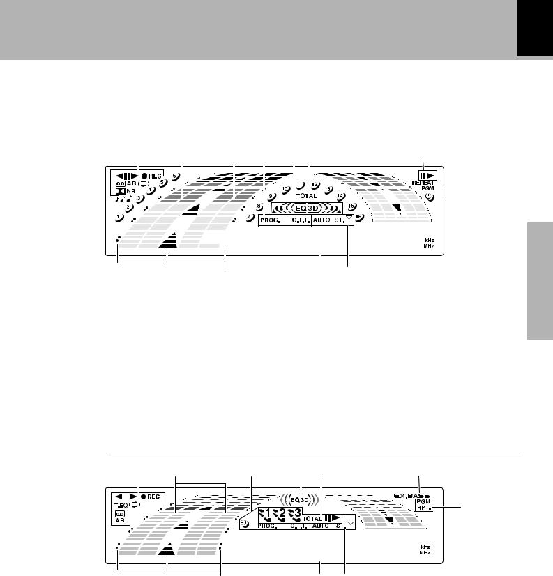
1 Cassette deck-related indicators |
5 CD player-related indicators |
||
This section contains the cassette deck operation indicators. The indicated information includes the tape reverse mode and tape transport direction.
2Sound level meter
The display varies according to the music or the opera-
tions of the CD, tape, etc.
During the volume adjustment, this meter displays the current sound level as a reference.
3 Timer-related indicators
4XD-7...series :
Equalizer/3D surround/“S. direct” indicators XD-8...series :
Equalizer/DSP/“S. direct” indicators
This section contains the CD play and pause mode indicators. It also shows the track numbers in the current disc.
6 REPEAT/PGM indicators
7 Sleep timer indicator
8 Tuner-related indicators
9 Character information display
Displays the input selection, frequency, volume level, etc.
0Guideline
Blinks during the setting of an item using the jog dial.
section Preparation
XD-6...series
1 |
2 |
3 |
4 5 |
6 |
|||
|
|
|
|
|
|
|
|
|
|
|
|
|
|
|
|
7
• • • • • • • • •
09 8
1 Cassette deck-related indicators |
5 CD player-related indicators |
This section contains the cassette deck operation indicators. The indicated information includes the tape reverse mode and tape transport direction.
2Sound level meter
The display varies according to the music or the operations of the CD, tape, etc.
During the volume adjustment, this meter displaysthe current sound level as a reference.
3 Timer-related indicators
4 Equalizer/DSP/“S. direct” indicators
This section contains the CD play and pause mode indicators. It also shows the disc number being selected.
6 EX.BASS indicator
7 PGM/RPT. indicators
8 Tuner-related indicators
9Character information display
Displays the input selection, frequency, volume level,
etc.
0 Guideline
Blinks during the setting of an item using the jog dial.

14
Main unit
Controls and indicators
XD-SERIES (EN/M,T)
|
|
|
|
678 |
|
9 |
|
0 |
|
|
|
|
|
|
|
|
|
|
|
|
|
|
|
|
XD-6...series, XD-8...series only |
|
|||
|
|
|
|
|
|
MINI HI-FI COMPONENT SYSTEM |
|
|
|
|
|
|||
|
|
|
|
|
|
|
XD-552 |
|
|
|
|
|
|
|
|
1 |
|
|
STANDBY |
|
|
|
|
|
|
|
BAND |
! |
|
|
|
|
TIMER |
|
|
|
|
|
|
|
|
|
||
|
|
ON/STANDBY |
|
|
|
|
|
|
|
TUNING MODE |
|
|||
|
|
|
|
|
|
|
|
|
|
|
||||
|
2 |
|
|
|
|
|
|
|
|
|
|
|
|
|
|
|
|
|
|
|
|
|
|
|
|
R D S |
|
|
|
|
|
MIC VOL. |
|
|
|
|
|
|
|
|
|
|
|
@ |
|
|
|
ND CONT |
|
|
|
O |
|
RDS |
TP PTY |
EON TA |
|
DOWN VOLUME |
|
|
|
|
|
|
|
|
|
CONTROL |
|
|||||
|
|
|
RO |
|
|
LTI C NT |
RO |
|
|
|||||
|
|
|
OU |
BACK |
U |
|
|
|
|
|
|
|||
|
|
|
S |
L |
M |
|
L |
|
|
|
|
|
# |
|
section |
|
MIN. MAX. |
|
|
|
|
|
|
NEWS PRO LOGIC 3 STEREO |
VIRTUAL |
|
|
||
|
MIC |
|
|
|
|
|
|
|
|
|
||||
|
|
|
|
|
|
|
|
|
|
|
|
|
||
|
|
|
|
|
|
|
|
|
|
DISPLAY |
|
UP |
$ SUPER WOOFER |
|
|
|
|
|
MENU |
|
|
|
|
INPUT /DEMO |
|
|
|
||
Preparation |
|
|
|
|
|
|
|
SELECT |
|
|
|
|
||
|
|
|
|
|
|
|
|
|
|
|
|
|||
3 |
|
|
|
|
|
|
|
|
|
EX.BASS |
|
|
XD-7...series only |
|
|
|
|
|
|
|
|
|
|
|
|
|
|
||
4 |
PHONES |
|
|
|
|
|
|
ENTER |
|
|
DOWN |
UP |
|
|
|
|
|
|
|
|
|
|
|
|
|
|
|||
|
|
|
|
|
|
|
|
|
|
|
|
|
||
5 |
|
|
|
|
|
|
|
|
|
|
|
|
||
|
|
|
|
|
|
|
|
|
|
|
|
% |
||
|
& |
0 |
|
|
|
|
|
|
|
|
|
|
0 |
^ |
|
PUSH |
|
|
|
|
|
|
|
|
|
|
PUSH |
|
|
|
|
OPEN |
|
|
|
|
|
|
|
|
|
|
OPEN |
|
|
* DOLBY NR |
|
|
|
|
|
|
|
|
|
|
|
) |
|
|
XD-7...series, XD-8...series only |
|
|
|
|
|
|
|
|
|
||||
|
|
|
|
|
|
|
|
|
|
|
||||
|
TAPE EQ. |
|
|
|
|
|
|
|
|
|
|
|
|
|
|
XD-6...series only |
|
|
|
|
|
|
|
|
|
|
|
¡ |
|
|
|
A PLAY |
|
AUTO REVERSE |
|
AUTO REVERSE |
|
REC/ |
B |
|||||
|
|
|
|
|
|
|||||||||
|
|
DIRECT PROGRAM SEARCH SYSTEM |
|
DIRECT PROGRAM SEARCH SYSTEM |
PLAY |
|
||||||||
|
( |
|
|
|
|
|
|
|
|
|
|
|
|
™ |
|
|
|
|
|
@ |
|
& |
# |
|
|
|
|
£ |
|
|
|
|
REV. MODE |
TAPE EQ. |
1 |
|
¡ A B |
REC/ARM |
|
|||||
|
¢ |
|
|
|
|
|
|
|
|
|
|
|
|
¶ |
|
° |
DISC |
|
|
|
|
|
|
|
& |
|
^ |
0 |
• |
|
SKIP |
DISC1 |
DISC2 |
DISC3 |
|
|
|
OPEN |
||||||
|
§ |
|
|
|
|
|
|
|
|
|
|
|
|
|
CD player unit
¢ DISC SELECTOR keys |
° |
The disc for playback (or recording) is selected.
DISC SELECTOR indicators
(XD-7...series, XD-8...series only)
The indicators corresponding to the trays accommodating discs light up. During playback of a CD, the indicator corresponding to the CD blinks.
° DISC SKIP key |
° |
§ Disc tray |
¢ |
Three discs can be stored. |
|
¶ CD operation keys |
¢° |
Play/pause (^) key |
|
Stop (&) key |
|
• Tray open/close (0OPEN) key |
¢ |
The disc tray is opened and closed. |
|
The disc for playback (or recording) is selected. This is also used for insertion of a CD to the inside of the disc tray.

Controls and indicators 15
XD-SERIES (EN/M,T)
Receiver
1ON/STANDBY ( |
|
|
) key |
™ |
|
|
|||
|
|
|||
Power ON/OFF switching is executed. |
|
|||
2STANDBY indicator |
|
£ |
||
The indicator lights up when the power is set to the STANDBY mode.
TIMER indicator |
P´ |
The indicator lights up together with the STANDBY indicator when the power is set to the STANDBY mode after having activated a timer program.
3PHONES jack |
™ |
For connection of a headphone (optional). |
|
4SOUND CONTROL jog dial |
|
@*()WE
Turn this dial to select or cancel the equalizer pattern, etc.
5MULTI CONTROL jog dial
*(°º
Turn this dial to select optimum modes according to the desired operations.
When the CD input is selected, this dial is used to skip tracks.
When the TUNER input is selected, this dial is used to select a station.
6MENU key |
*( |
Press to switch the mode set with the MULTI CONTROL jog dial ON or OFF. The item selected by this key is variable depending on the current operation mode.
MENU indicator
(XD-7...series, XD-8...series only)
The indicator starts to blink when the MENU key is pressed.
7BACK key |
*( |
Press when setting a mode using the MULTI CONTROL jog dial to return to the previous step and restart the operation from there.
8Display |
# |
9Icon indicators |
*( |
(CD PGM, REC. , DUBBING, AUDIO, CLOCK, SURROUND)
When a mode is set using the MULTI CONTROL jog dial, the icon indicators corresponding to the current mode light up.
(The SURROUND icon is displayed only with the XD-6...
series, XD-8...series models.)
0RDS-related indicators
(For U.K., Europe and Russia) |
q |
Surround-related indicators |
E |
(XD-6...series, XD-8...series only) |
|
!Tuner operation keys |
º |
BAND key |
|
Press to switch the receiving band. |
|
TUNING MODE key |
|
Switches the tuning mode. |
|
@VOLUME CONTROL knob |
™ |
This is used for volume adjustment. |
|
#INPUT key |
™ |
Press to select the input source. When TAPE or CD is selected, playback starts automatically provided that a tape or disc has already been loaded.
DISPLAY/DEMO key |
6› |
|
Switches the displayed information. |
|
|
When power is STANDBY: |
|
|
Switches the demonstration on and off. |
|
|
$EX. BASS (Extra bass) key |
|
£ |
(XD-6...series, XD-8...series only) |
|
|
Switches the extra bass play on and off. |
|
|
EX.BASS indicator (XD-8...series only) |
£ |
|
SUPER WOOFER key (XD-7...series only) |
£ |
|
Press to switch the super woofer on and off.
SUPER WOOFER indicator (XD-7...series only)
%SELECT key |
£ |
*(I |
Used for setting of various modes or establishing a selection.
When power is STANDBY:
Used for displaying the time. (When this key is pressed while the “TIMER” indicator is lit, the “PROG.” or “O.T.T.” indicator also lights up, the timer reservation setting mode is displayed, then the display returns to the previous condition.)
^ENTER key |
*( |
Used for entering a selected mode in memory or executing it.
section Preparation
Cassette deck unit
&A deck cassette holder
Press the area marked 0PUSH OPEN to load or eject a tape.
* DOLBY NR key (XD-7...series, XD-8...series only)
‹
Dolby noise reduction ON/OFF switching is executed.
TAPE EQ. key (XD-6...series only) |
¶ |
Press to switch the Tape Equalizer on and off. |
|
( REV. MODE key |
¶‹ |
The reverse mode of the deck (both sides, repeated, one side) is switched.
)B deck cassette holder
Press the area marked 0 PUSH OPEN to load or eject a tape.
¡ Cassette deck operation keys |
§¶ |
Play (@ #) keys |
|
Stop (&) key |
|
Fast forward and rewind (1 ¡) keys |
|
™ A/B key |
§ |
Press to select the deck to be operated.
(For U.K. and Russia) |
› |
Used as the beat cancel key during recording ofAM(MW)/ |
|
LW broadcasting. |
|
£ REC/ARM key |
‹› |
Press to start recording. Pressing the key during recording stops it after leaving a non-recorded space (blank) of about 4 seconds.
16
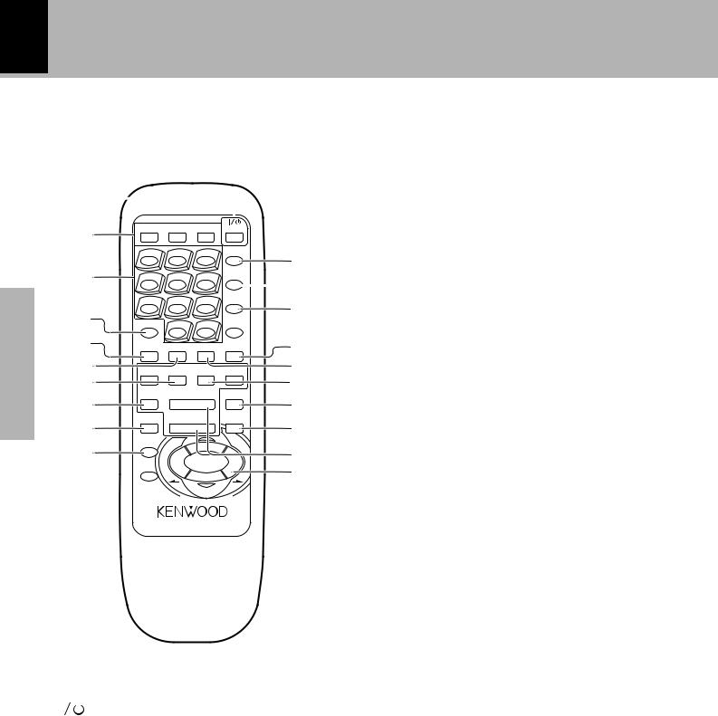
Remote control unit (XD-7...series)
Controls and indicators
XD-SERIES (EN/M,T)
The keys on the remote control unit with the same names as on the main unit have the same function as the keys on the main unit.
Preparation section
1
2 |
TA/NEWS RDS DISP. |
PTY |
POWER |
|
||
|
|
|
|
|
|
|
|
1 |
2 |
|
3 |
SOUND |
|
|
|
CONTROL |
@ |
|||
|
|
|
|
|
|
|
3 |
4 |
5 |
|
6 |
SUPER |
|
|
WOOFER |
# |
||||
|
|
|
|
|
|
|
|
7 |
8 |
|
9 |
INPUT |
$ |
4 |
|
|
|
|
|
|
DISC SKIP |
0 |
|
+10 |
BAND |
|
|
|
|
% |
||||
5 |
|
|
|
|
|
|
TIME |
RANDOM |
REPEAT TEXT DISP. |
^ |
|||
|
||||||
6 |
2 TAPE 3 |
|
1TUNING¡ & |
|||
7 |
TAPE |
|
|
6 MUTE |
* |
|
|
CD |
|
|
|||
8 |
A/B |
|
( |
|||
|
7 |
|
||||
9 |
BACK |
MENU |
) |
|||
|
|
|
|
|
||
0 |
SELECT |
4 |
|
|
¢ |
|
|
|
|
|
|
¡ |
|
! |
ENTER |
|
|
|
|
™ |
|
|
|
|
|
||
|
|
|
|
|
|
|
|
|
|
|
VOLUME |
|
|
|
|
M |
|
OL |
|
|
|
|
|
ULTI CONTR |
|
|
|
5 TIME key |
° |
Press to switch the time information on the CD player unit.
6 RANDOM key |
‚ |
For CD playback, switching is executed between random playback and normal playback.
7 TAPE play (2 3) keys |
§ |
8 TAPE A/B key |
§› |
9 BACK key |
* |
0 SELECT key |
* |
! ENTER key |
* |
@ SOUND CONTROL key |
*W |
Press to select or cancel the equalizer and 3D surround |
|
settings. |
|
# SUPER WOOFER key |
£ |
$ INPUT key |
™ |
% BAND key |
º |
^ TEXT DISP. key |
y |
Press to switch the text information recorded in a CD |
|
TEXT disc. |
|
& REPEAT key |
° |
Used for repeated playback of a CD.
|
|
|
REMOTE CONTROL UNIT |
|
|
* TUNING (1 ¡) keys (CD/TAPE/TUNER) |
|
|
|
|
RC-752E |
|
|
||
|
|
|
|
|
|
°¶º |
|
|
|
|
|
|
|
When the CD or TAPE input is selected, press to fast |
|
|
|
|
|
|
|
forward or backward (rewind) the disc or tape. |
|
|
|
|
|
|
|
When the TUNER input is selected, press to select a |
|
|
|
|
|
|
|
station. |
|
|
|
|
|
|
|
( MUTE key |
£ |
|
|
|
|
|
|
This is used to mute the sound temporarily. |
|
|
|
|
|
|
|
) MENU key |
* |
|
|
|
For U.K., Europe and Russia |
: RC-752E |
|
¡ CD play/pause (6) key |
¢ |
|
|
|
Other countries |
: RC-752 |
|
Stop (7) key |
°⁄ |
|
|
|
|
|
|
™ MULTI CONTROL/VOLUME keys |
*™ |
1 |
|
|
POWER key |
|
™ |
Skip/preset call (4, ¢) keys (CD/TUNER) |
|
|
|
|
|||||
|
|
|
|||||
|
|
||||||
|
Power ON/OFF switching is executed. |
|
|
°⁄ |
|||
2 RDS-related keys (For U.K., Europe and Russia) |
The left and right keys have the same functions as the |
||||||
|
TA/NEWS key |
|
r |
MULTI CONTROL jog dial on the main unit. |
|||
|
Used for automatic reception of transmissions of a |
When the CD input is selected, press to skip forward or |
|||||
|
certain content. |
|
|
backward on the disc. |
|
||
|
RDS DISP. key |
|
q |
When the TUNER input is selected, press to select |
|||
|
The display contents are switched during reception of |
preset station. |
|
||||
|
The top and bottom keys are used to adjust the volume. |
||||||
|
RDS broadcasts. |
|
|
||||
|
|
|
|
|
|||
|
PTY key |
|
w |
|
|
||
|
This is used to specify the program type when search- |
|
|
||||
|
ing for a station. |
|
|
|
|
||
3 Numeric keys |
|
° |
|
|
|||
|
Used as number keys when the input is CD or TUNER. |
|
|
||||
4 DISC SKIP key |
|
° |
|
|
|||
Controls and indicators 17
XD-SERIES (EN/M,T)
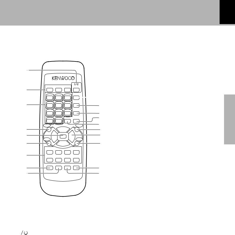
Remote control unit (XD-6...series, XD-8...series)
The keys on the remote control unit with the same names as on the main unit have the same function as the keys on the main unit.
1 |
|
|
|
|
|
|
|
|
|
2 |
TA/NEWS RDS DISP. |
PTY |
POWER |
|
|||||
|
|
|
|
|
|
|
SOUND |
|
|
|
1 |
|
2 |
|
3 |
|
|
||
|
|
|
|
CONTROL |
0 |
||||
|
|
|
|
|
|
|
|
|
|
3 |
4 |
|
5 |
|
6 |
|
EX.BASS |
|
|
|
|
|
|
! |
|||||
|
|
|
|
|
|
|
LISTEN |
||
|
7 |
|
8 |
|
9 |
|
|
||
|
|
|
|
MODE |
@ |
||||
|
|
|
|
|
|
|
|
|
|
|
0 |
+10 |
BAND |
INPUT |
# |
||||
|
|
||||||||
|
BACK |
|
|
|
M |
E U |
|
MUTE |
$ |
|
|
OLU |
|
|
|||||
4 |
|
|
V |
|
|
P |
|
|
% |
2 |
|
|
|
|
|
|
3 |
||
5 |
|
|
|
|
|
|
^ |
||
|
4 |
|
|
|
SELECT |
|
¢ |
|
|
|
ENTER |
|
MULTI CONTROL |
|
MENU |
|
|||
6 |
|
V |
OL |
|
|
|
N |
|
& |
|
|
|
|
|
|
|
|||
|
|
|
|
|
W |
|
|
||
|
|
|
|
UME DO |
|
CD6 |
|
||
|
1 TUNING ¡ 7 |
|
|
||||||
7 |
2 TAPE 3 |
TAPE |
|
|
A/B |
DISC SKIP |
|
8 |
TEXT DISP. TIME |
RANDOM |
REPEAT |
|
|
* |
|
9 |
|
|
( |
|
REMOTE CONTROL UNIT |
||
|
RC-852E |
|
|
|
|
For U.K., Europe and Russia |
: RC-852E |
|
|
Other countries |
: RC-852 |
1 |
|
POWER key |
™ |
|
|||
|
Power ON/OFF switching is executed.
2 RDS-related keys (For U.K., Europe and Russia) TA/NEWS key r
Used for automatic reception of transmissions of a certain content.
RDS DISP. key |
q |
The display contents are switched during reception of RDS broadcasts.
PTY key |
w |
This is used to specify the program type when searching for a station.
3 Numeric keys |
° |
Used as number keys when the input is CD or TUNER. |
|
4 BACK key |
( |
5 SELECT key |
( |
6 ENTER key |
( |
7 TUNING (1 ¡) keys (CD/TAPE/TUNER) |
|
|
°¶º |
When the CD or TAPE input is selected, press to fast forward or backward (rewind) the disc or tape.
When the TUNER input is selected, press to select a
station. |
|
Stop (7) key |
°⁄ |
CD play/pause (6) key |
¢ |
TAPE play (2 3) keys |
§ |
TAPE A/B key |
§› |
DISC SKIP key |
° |
8 TEXT DISP. key |
y |
Press to switch the text information recorded in a CD |
|
TEXT disc. |
|
9 TIME key |
° |
Press to switch the time information on the CD player |
|
unit. |
|
0 SOUND CONTROL key |
(E |
Press to select the equalizer pattern, DSP play or |
|
surround play. |
|
! EX. BASS key |
£ |
@ LISTEN MODE key |
E |
Press to select surround playback mode. |
|
# INPUT key |
™ |
$ BAND key |
º |
% MUTE key |
£ |
This is used to mute the sound temporarily. |
|
^ MULTI CONTROL/VOLUME UP, DOWN keys
(™
Skip/preset call (4, ¢) keys (CD/TUNER)
°⁄
The left and right keys have the same functions as the MULTI CONTROL jog dial on the main unit.
When the CD input is selected, press to skip forward or backward on the disc.
When the TUNER input is selected, press to select preset station.
The top and bottom keys are used to adjust the volume.
& MENU key |
( |
* REPEAT key |
° |
Used for repeated playback of a CD. |
|
( RANDOM key |
‚ |
For CD playback, switching is executed between random playback and normal playback.
section Preparation
18 Operation of jog dials (XD-7...series)
XD-SERIES (EN/M,T)
Preparation section
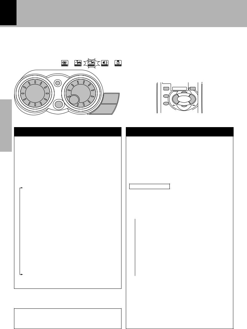
This unit has two jog dials named the MULTI CONTROL and SOUND CONTROL jog dials.
The MULTI CONTROL jog dial makes it possible to set (establish) many functions in a simple procedure. When the MENU key is pressed, the icon indicators light according to the MULTI CONTROL jog dial operation so you can select the desired mode based on a more intuitive method.
|
|
D |
|
UN |
|
O |
|
|
S |
|
|
CONTROL
CD PGM REC. DUBBING AUDIO CLOCK
|
|
|
TI |
CO |
|
|
|
|
|
N |
TR |
|
|
|
|
L |
|
O |
||
BACK |
U |
|
|
|
||
M |
|
|
|
|
L |
|
MENU
SELECT
ENTER
Icon indication example:
When “Tape Dubbing” is selected with the MULTI CONTROL jog dial (or the MULTI CONTROL key on the remote control unit), the “DUBBING” icon indicator lights up.
BACK |
7 |
MENU |
SELECT 4  ¢
¢
ENTER
VOLUME
M |
OL |
|
ULTI CONTR |
SOUND CONTROL jog dial
The SOUND CONTROL jog dial (or the SOUND CONTROL key on the remote control unit) makes it possible
to select a tone or sound effect in an easy procedure.
W
The following items can be selected by turning the SOUND CONTROL jog dial.
“Rock” .................. |
Rock music |
||
“Pop” .................... |
Pop music |
||
“Jazz” ................... |
Jazz music |
||
“Classic” ............... |
Classical music |
||
“Disco” ................. |
Disco music |
||
“Movie” ................ |
Movie music |
||
“3D Level 1” ......... |
3D surround level 1 |
||
“3D Level 2” ......... |
3D surround level 2 |
||
“Custom EQ 1” |
|
|
Equalizer’s manual |
|
|||
“Custom EQ 2” |
|
memory created by the |
|
|
|||
“Custom EQ 3” |
|
|
user |
|
|
|
|
“S. direct” ............. |
Pure sound reproduction by |
||
|
|
turning the equalizer or 3D |
|
|
|
surround circuitry off. |
|
“Effect off” ............ |
Normal playback |
||
In the MULTI CONTROL setting mode (while the guideline is blinking), the BAND and play keys are defeated and inoperative.
MULTI CONTROL jog dial
1Press the MENU key to enter the MULTI CONTROL setting mode.
2 Select an operation mode by turning the MULTI
CONTROL jog dial (or pressing the MULTI CONTROL keys on the remote control unit).
3Set, establish or execute (determine) items by pressing the SELECT key and/or ENTER key.
Display examples
The following items can be selected by turning the MULTI CONTROL jog dial.
The messages inside ( ) may not be displayed under certain situations.
 (“CD Program Play”)
Only when the CD input is selected
(“Recording Options”)
Only when a recordable tape is loaded in Deck B
(“Tape Dubbing”)
Only when the TAPE input is selected, the tape to be played is loaded in Deck A and a recordable tape is loaded in Deck B
“Audio Options”
 “Clock Options”
÷To cancel the mode for setting (using) MULTI CONTROL, read the description of each item in this manual.
÷Press the BACK key to return to the previous step and restart operation from there. (The BACK key is inoperative once scrolling message “Press ' ENTER ' to Start” has been displayed.)
Operation of jog dials (XD-6...series, XD-8...series) |
|
19 |
|
|
|
|
XD-SERIES (EN/M,T) |
|
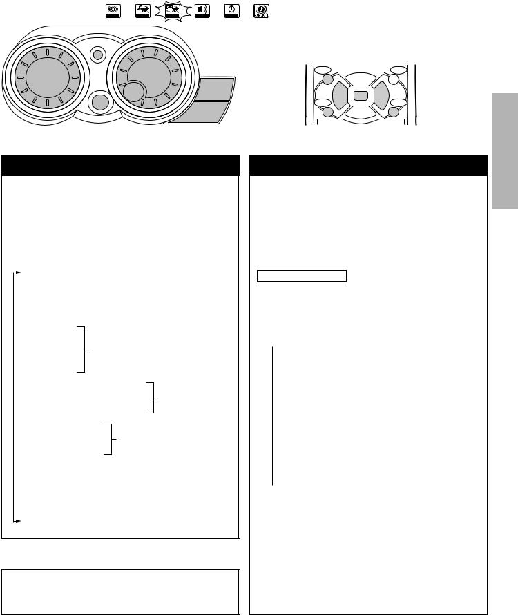
This unit has two jog dials named the MULTI CONTROL and SOUND CONTROL jog dials.
The MULTI CONTROL jog dial makes it possible to set (establish) many functions in a simple procedure. When the MENU key is pressed, the icon indicators light according to the MULTI CONTROL jog dial operation so you can select the desired mode based on a more intuitive method.
|
|
D |
|
UN |
|
O |
|
|
S |
|
|
CONTROL
CD PGM REC. DUBBING AUDIO CLOCK
TI |
CO |
|
NT |
R |
|
UL |
|
|
M |
|
OL |
SELECT
Icon indication example:
When “Tape Dubbing” is selected with the MULTI CONTROL jog dial (or the MULTI CONTROL key on the remote control unit), the “DUBBING” icon indicator lights up.
BACK |
OLUME U |
P |
MUTE |
|
V |
|
|
4 |
SELECT |
|
¢ |
23
ENTER MULTI CONTROL MENU
V |
OL |
|
N |
|
W |
||
|
|
UME DO |
|
MULTI CONTROL jog dial
1Press the MENU key to enter the MULTI CONTROL setting mode.
2 Select an operation mode by turning the MULTI
CONTROL jog dial (or pressing the MULTI CONTROL keys on the remote control unit).
3Set, establish or execute (determine) items by pressing the SELECT key and/or ENTER key.
Display examples
The following items can be selected by turning the MULTI CONTROL jog dial.
The messages inside ( ) may not be displayed under certain situations.
 (“CD Program Play”)
Only when the CD input is selected
(“Recording Options”)
Only when a recordable tape is loaded in Deck B
(“Tape Dubbing”)*
Only when the TAPE input is selected, the tape to be played is loaded in Deck A and a recordable tape is loaded in Deck B
“Audio Options”
“Clock Options”
 “Surround Setup”
*“Tape Dubbing” cannot be selected during DSP or surround playback.
÷To cancel the mode for setting (using) MULTI CONTROL, read the description of each item in this manual.
÷Press the BACK key to return to the previous step and restart operation from there. (The BACK key is inoperative once scrolling message “Press ' ENTER ' to Start” has been displayed.)
section Preparation
20 Operation of remote control unit
XD-SERIES (EN/M,T)
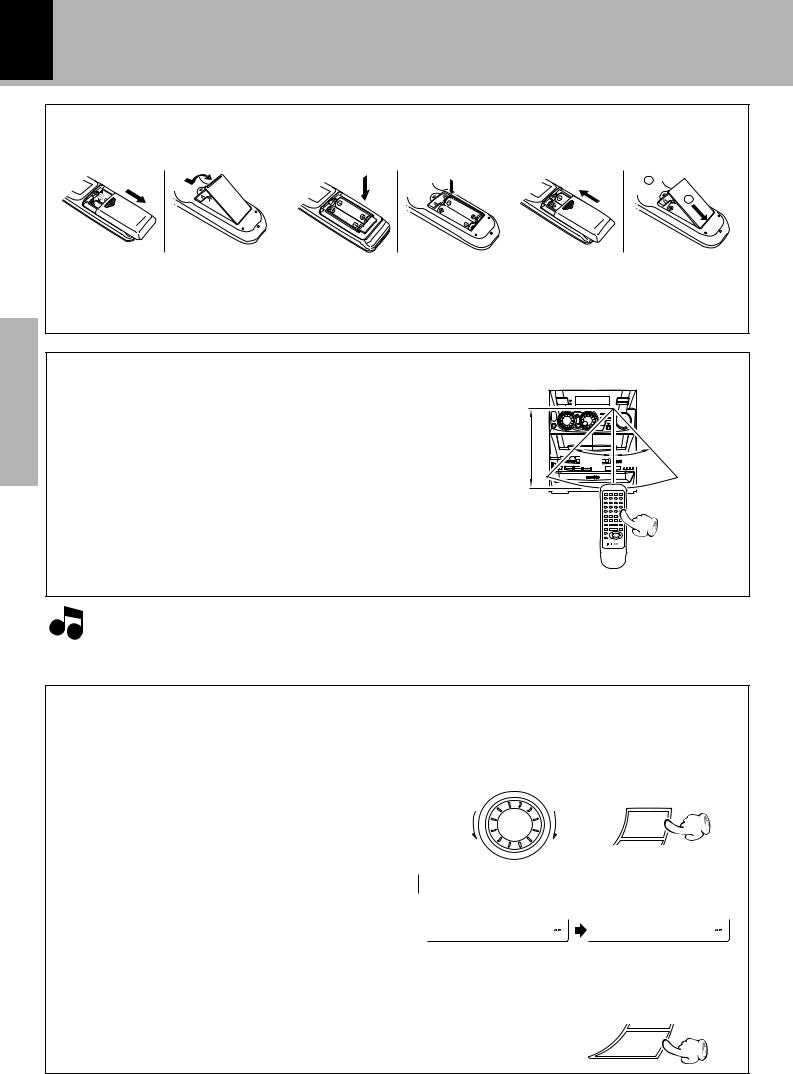
Loading batteries
1 Remove the cover. |
2 Insert batteries. |
3 Close the cover. |
2
1
XD-6...series XD-7...series
XD-8...series
Preparation section
÷Insert two R6 (“AA”-size) batteries following the polarity indications.
Operation
Plug the power cord into the mains power outlet and press the on/standby (

 POWER) key of the remote control unit to turn power ON. After the power has been turned ON, press the desired key.
Toturnpoweroff,presstheon/standby(

 POWER) key again.
The power mode enters the STANDBY mode in which the “STANDBY” indicator lights up. (The “TIMER” indicator also lights in this mode if a timer program has been activated.)
÷When pressing more than one remote control keys successively, press the keys securely by leaving an interval of 1 second or more between keys.
Operating |
range |
Remote sensor |
|
||
(approx.) |
|
|
|
6m |
|
|
30˚ |
30˚ |
 1.The provided batteries are intended for use in operation checking, and their service life may be short. Notes 2.When the remote controllable distance becomes short, replace both of the batteries with new ones.
3.If direct sunlight or the light of a highfrequency fluorescent lamp (inverter type, etc.) is incident to the remote sensor, malfunction may occur. In such a case, change the installation position to avoid malfunction.
CHANNEL SPACE setting
(Except for the U.S.A., Canada, U.K., Europe, Australia and Russia)
The space between radio channels has been set to the one that prevails in the area to which the system is shipped. However, if the current channel space setting does not match the setting in the area where the system is to be used, for instance when you move from area 1 or area 2 shown in the following table or vice versa, proper reception of AM/FM (MW/FM) broadcasts cannot be expected. In this case, change the channel space setting in accordance with your area by referring to the following table.
|
Area |
CHANNEL |
||
|
SPACE freq. |
|||
|
|
|||
|
|
|
|
|
1 |
USA, Canada and South |
FM |
: |
100 kHz |
|
American countries |
AM |
: |
10 kHz |
2 |
Other countries |
FM |
: |
50 kHz |
|
|
AM : |
9 kHz |
|
|
|
|
|
|
1 Select the TUNER input.
2While holding the SELECT key depressed, turn the SOUND CONTROL jog dial to select the
system mode.
ND CONT |
R |
|
U |
O |
|
O |
|
|
S |
|
L |
SELECT
 1 “FM100/AM10 kHz” STEP,
  2 “FM 50 /AM 9 kHz” STEP,
F M 1 0 0 / A M 1 0 |
F M 5 0 / A M 9 |
÷The “AM” display is variable depending on the model (country or area), and “MW” may be displayed in some areas.
3 Establish the selection.
ENTER
Handling of discs and tapes
21
XD-SERIES (EN/M,T)
Disc handling precautions
Handling
Hold the discs so that you do not touch the playing surface.
Label side
Playing side
Sticker Do not attach paper or tape to either the playing side or the label side of the discs.
Sticky paste
Cleaning
If fingerprints or foreign matter become attached to the disc, lightly wipe the disc with a soft cotton cloth (or similar) from the center of the disc outwards in a radial manner.
Storage
When a disc is not to be played for a long period of time, remove it from the player and store it in its case.
Discs which can be played with this unit
CD (12 cm, 8 cm), and the audio part of CDV, CD-G, CD-EG and CD-EXTRA.
Use discs that comply with the IEC standard, for example a disc carrying the marking on the label surface.
Never play a cracked or warped disc
During playback, the disc rotates at high speed in the player. Therefore, to avoid danger, never use a cracked or deformed disc or a disc repaired with tape or adhesive agent.
Please do not use discs which are not round because they may cause a malfunction.
Disc accessories
The disc accessories (stabilizer, protection sheet, protection ring, etc.) which are marketed for improving the sound quality or protecting discs as well as the disc cleaner should not be used with this system because they may cause malfunction.
section Preparation
Notes on cassette tape
Safety tab (accidental erasure prevention tab)
After an important recording has been finished, break the safety tab, to prevent the recorded contents from being erased or recorded on accidentally.
To store cassette tapes
Do not store the tapes in a place which is subject to direct sunlight, or near equipment that generates heat. Keep the cassette tapes away from any magnetic field.
N
S
For A side
For B side
When there is slack in the tape
In such a case, insert a pencil into the reel hole and wind the reel hub to remove the slack.
To re-record Apply tape only to the position where the tab has been removed.
1.Longer tape than 110 minutes cassette tape
Notes Since longer tape than 110 minutes cassette tape is very thin, the tape could adhere to the pinch roller or be easily cut. It is recommended that these tapes not be used with this unit to prevent possible damage.
2.Endless tapes
Do not use an endless tape, as this could damage the mechanism of the unit.
22 Let’s put out some sound
XD-SERIES (EN/M,T)
Basic use method
Basic section
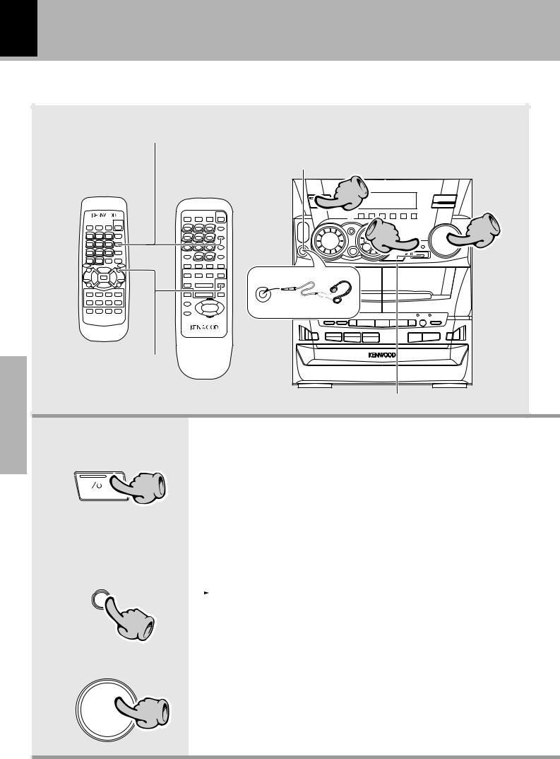
Reproducing sound |
Listening through headphones |
|
Insert the headphone plug into the PHONES jack. |
||
with enhanced bass |
÷The sounds from all speakers are cut off.
÷The “Effect off” mode will be automatically engaged during DSP playback or surround playback.
XD-6...series |
|
1 |
|
XD-8...series |
XD-7...series |
|
|
|
|
||
|
|
|
R D S |
|
|
2 |
3 |
|
|
PHONES |
|
|
|
|
|
Muting the sound temporarily |
|
|
|
Reproducing sound with enhanced bass
1. Switching the power ON (OFF)
When the power is ON, pressing the ON/STANDBY key enters the power
STANDBY mode, in which the standby indicator lights up.
|
|
|
1 |
|
|
|
|
One-touch operation function |
||
|
|
|
|
|
|
|||||
ON/STANDBY |
|
|
|
|
The power can also be turned ON by pressing the play key of the CD |
|||||
|
|
|
|
|
|
|
|
|||
|
|
|
|
|
|
|
|
player, the play key of the cassette deck or the BAND key of the tuner. |
||
|
|
|
|
|
|
|
|
It is also possible to turn the power ON by simply pressing the 0OPEN |
||
|
|
|
|
|
|
|
|
key. |
|
|
|
|
|
|
|
|
|
|
|
||
|
|
|
|
|
|
|
|
|
|
|
|
|
|
|
|
|
|
|
|
||
INPUT |
|
2. Selecting the desired output |
||||||||
|
|
|
|
|
1 TUNER (Radio) |
º ÷ If you select the MD/DVD (external |
||||
|
|
|
|
|
|
|
|
|||
|
|
|
|
|
|
|
|
2 CD |
¢ |
input) mode, also read the instruction |
|
|
|
2 |
|
|
|
|
3 TAPE |
|
manual of the component connected |
|
|
|
|
|
|
|
§ to the MD/DVD INPUT jacks. |
|||
|
|
|
|
|
|
|
|
|||
|
|
|
|
|
|
|
|
4 MD/DVD (External input) |
|
|
|
|
|
|
|
|
|
|
|||
|
|
|
|
|
|
|
|
|
!Q |
|
|
|
|
|
|
|
|
|
|
||
|
|
|
|
|
|
|
|
|
||
|
|
|
CONTROLVOLUME 3. Volume adjustment |
|
||||||
|
|
|
3 |
|
|
|
|
|
|
÷ The display shows a reference value. |
DOWN |
UP |
|
|
|
|
|
|
(The reference value is also shown visu- |
||
|
|
|
|
|
|
ally by the sound level meter.) |
||||
 Loading...