


XD-751
Table of contents
 Loading...
Kenwood XD-751, XD-701, XD-771S, XD-571S, XD-501 User Manual
...
B60-3768-00 00 MA (Y,M,X,T,Q)
99/12 11 10 9 8 7 6 5 4 3 2 1 98/12 11 10 9 8 7 6 5 4 3 2 1
MC
COMPONENT SYSTEM/COMPACT HI-FI SYSTEM
INSTRUCTION MANUAL
KENWOOD CORPORATION
This instruction manual is used to describe multiple models listed above.
Model availability and features (functions) may differ depending on the country and sales
area.
‰
XD SERIES
XD-751/XD-701
XD-771S
XD-551/XD-501
XD-571S
XD-SERIES (En)
2
Preparation sectionBasic sectionApplication sectionKnowledge sections
Before applying power
Units are designed for operation as follows.
U.S.A. and Canada...................................................................AC 120 V only
Austraria....................................................................................AC 240 V only
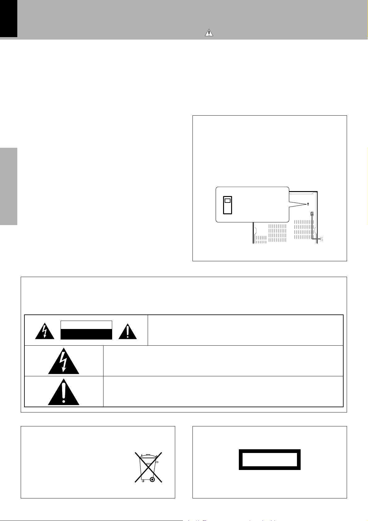
The marking is located on the rear panel and says that the compo-
nent uses laser beams that have been classified as Class 1. It means
that the unit is utilizing laser beams that are of a weaker class. There
is no danger of hazardous radiation outside the unit.
CLASS 1
LASER PRODUCT
The marking of products using lasers
(Except for some areas)
REQUIREMENT BY NEDERLAND GAZETTE
Batteries are supplied with this product. When
they empty, you should not throw away . Instead,
hand them in as small chemical waste.
5Caution : Read this page carefully to ensure safe operation.
Europe and U.K.........................................................................AC 230 V only
China and Russia .....................................................................AC 220 V only
*Other countries ................................ AC 110-120 / 220-240 V switchable
*AC voltage selection
The AC voltage selector switch on the rear panel is set to the voltage
that prevails in the area to which the unit is shipped. Before con-
necting the power cord to your AC outlet, make sure that the setting
position of this switch matches your line voltage. If not, it must be
set to your voltage in accordance with the following direction.
AC voltage selector switch
Move switch lever to match your line voltage
with a small screwdriver or other pointed tool.
Note:
Our warranty does not cover damage caused by excessive line volt-
age due to improper setting of the AC voltage selector switch.
Safety precautions
WARNING : TO PREVENT FIRE OR ELECTRIC SHOCK, DO NOT EXPOSE THIS APPLIANCE TO
RAIN OR MOISTURE.
CAUTION: TO REDUCE THE RISK OF ELECTRIC SHOCK, DO NOT REMOVE COVER
(OR BACK). NO USER-SERVICEABLE PARTS INSIDE. REFER SERVICING TO QUALI-
FIED SERVICE PERSONNEL.
RISK OF ELECTRIC SHOCK
DO NOT OPEN
THE LIGHTNING FLASH WITH ARROWHEAD SYMBOL, WITHIN AN EQUILA TERAL TRIANGLE, IS INTENDED
TO ALERT THE USER TO THE PRESENCE OF UNINSULATED “DANGEROUS VOLTAGE” WITHIN THE
PRODUCT’S ENCLOSURE THA T MA Y BE OF SUFFICIENT MAGNITUDE TO CONSTITUTE A RISK OF ELEC-
TRIC SHOCK TO PERSONS.
THE EXCLAMATION POINT WITHIN AN EQUILATERAL TRIANGLE IS INTENDED TO ALERT THE USER TO
THE PRESENCE OF IMPORTANT OPERATING AND MAINTENANCE (SERVICING) INSTRUCTIONS IN THE
LITERATURE ACCOMPANYING THE APPLIANCE.
CAUTION
%AC220-240V
~
fiAC110-120V
~
%AC220-240V
~
fiAC110-120V
~

XD-SERIES (En)
3
Preparation section Basic section Application section Knowledge sections
Contents
Preparation section Application section
Knowledge section
Before applying power ............................................ 2
Safety precautions ....................................................... 2
Special features ............................................................ 4
Handling of discs and tapes ........................................ 5
System connection (XD-7...series)......................... 6
Connection of the System Accessories ..................... 6
Connection of Options (Optional Parts) .................... 8
System connection (XD-5...series)....................... 10
Connection of the System Accessories ................... 10
Connection of Options (Optional Parts) .................. 12
Controls and indicators ......................................... 14
Main Unit..................................................................... 14
Display ......................................................................... 16
Remote control Unit................................................... 17
Operation of remote control unit .......................... 18
CHANNEL SPACE setting........................................... 18
Let's put out some sound....................................... 20
Basic use method ....................................................... 20
Playback of CD ............................................................ 22
Playback of tape ......................................................... 24
Searching for the desired music program (DPSS).. 27
Receiving broadcast station....................................... 28
Let's record .............................................................. 30
Recording (Deck B only) ............................................ 30
Copying tape (Tape dubbing)..................................... 33
Playback of CD ........................................................ 34
Listening in the desired sequence
(program playback) .............................................. 34
Repeated playback ..................................................... 36
Listening to an unexpected title sequence
(random playback) ................................................ 38
R.D.S. (Radio Data System)
(Except for some areas)......................................... 39
Searching for a desired program type
(PTY search)............................................................ 40
To be able to listen to the desired information
at any time .................................................................. 42
Convenient CD recording ....................................... 44
Selection of the convenient CD recording type...... 44
Recording only desired titles
(CD ONE TRACK RECORD)................................... 45
Recording of an entire CD
(CD RECORD) .......................................................... 46
Giving preference to the tape length over the title se-
quence (CD EDIT)........................................................ 47
Recording the programmed titles
(CD PGM RECORD) ................................................ 48
Effective Sound Adjustment ................................. 49
Adjustment of balance and input level..................... 49
Listening with the desired sound
(equalizer function)............................................... 50
Enjoying Sound Field Effects ..................................... 52
Enjoying Karaoke (Except for some areas)............... 53
Clock adjustment ..................................................... 54
Timer operation....................................................... 55
Sleep timer (SLEEP) .................................................... 55
Operate easy To use Timer
(Operate easy To use Timer:O.T.T.) ...................... 55
Timer programming .................................................... 56
Important Items ....................................................... 59
Maintenance................................................................ 59
Reference..................................................................... 59
In case of difficulty................................................. 60
Specifications ......................................................... 63
Before applying power
Caution : Read the pages marked
carefully to ensure safe operation.
Basic section
XD-SERIES (En)
4
Preparation sectionBasic sectionApplication sectionKnowledge sections
3D Wide FL display ^
The easy to see graphical display features a large spectrum analyzer. A running indicator shows the opera-
tions such as CD playback and skipping at a glance.
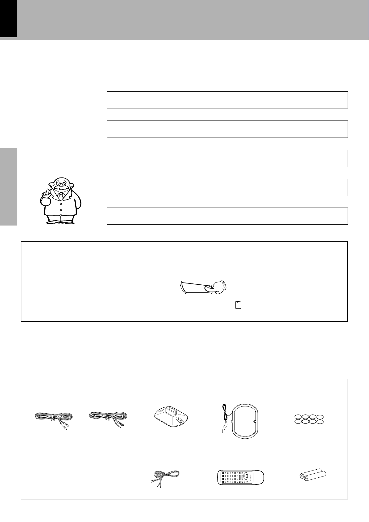
Speaker cords (4)
XD-7....Series
Speaker cords (2)
XD-5....Series
Batteries (R6/AA) (2)
Accessories
FM indoor antenna (1)
Remote control unit (1)
Loop antenna stand (1) AM loop antenna (1)
Each 3-way speaker incorporates an additional sub woofer to reproduce heavy bass more powerfully than
conventional system speakers.
Built in sub woofer (XD-7....series only) ¡
Easy to operate, new multi control jog dial (
The jog dial makes possible easy setup of CD playback, timer recording/playback and other operations while
monitoring the displayed information. The same operation is also available on the remote control unit.
Equalizer patterns can not only be selected from preset patterns, but patterns also can be created and
registered. It is possible to recreate a feeling of presence and to recreate a sound field.
Versatile tone and sound field adjustment p
Three discs can be set. There are various ways for enjoyment at the time of program playback, repeat
playback, random playback, etc.
3-Disc carousel CD player ™
Before applying power
Special features
Unpacking
Unpack the unit carefully and make sure that all accessories are put aside so they will not be lost.
Examine the unit for any possibility of shipping damage. If your unit is damaged or fails to operate, notify your dealer immediately. If your
unit was shipped to you directly, notify the shipping company without delay. Only the consignee (the person or company receiving the
unit) can file a claim against the carrier for shipping damage.
We recommend that you retain the original carton and packing materials for use should you transport or ship the unit in the future.
Demonstration
When the power supply is restored after a power failure or the power
cord is unplugged and plugged in again during use, this unit auto-
matically starts the demonstration function (display only). During the
demonstration, the display changes in sequence but the audio does
not change. The demonstration can be canceled with the following
procedure.
÷ Press the key during demonstration to stop it.
(Provided in the speaker package)
Europe and U.K. Other countries
Speaker cushion (8)
MODE
/DEMO
To switch over the demonstration:
Turn the unit OFF (STANDBY mode) and
press the key.
Each press of the key switches the demon-
stration as shown below.
1 DEMO (Demonstration executed)
2 OFF (Demonstration canceled)
XD-SERIES (En)
5
Preparation section Basic section Application section Knowledge sections
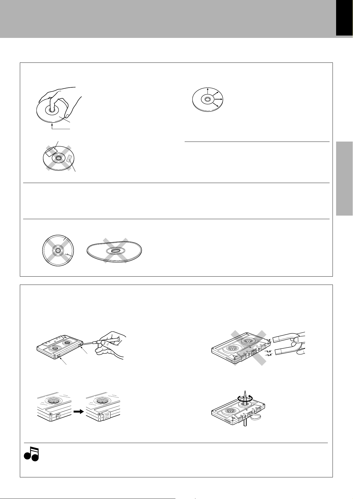
2. Endless tapes
Do not use an endless tape, as this could damage the mechanism of
the unit.
To re-record
Safety tab (accidental erasure prevention tab)
After an important recording has been finished, break the safety tab,
to prevent the recorded contents from being erased or recorded on
accidentally.
When there is slack in the tape
In such a case, insert a pencil into the reel hole and wind the reel hub
to remove the slack.
To store cassette tapes
Do not store the tapes in a place which is subject to direct sunlight, or
near equipment that generates heat. Keep the cassette tapes away
from any magnetic field.
For A side
For B side
Notes on cassette tape
Apply tape only to the position where
the tab has been removed.
1. Longer tape than 110 minutes cassette tape
Since longer tape than 110 minutes cassette tape is very
thin, the tape could adhere to the pinch roller or be easily cut.
It is recommended that these tapes not be used with this
unit to prevent possible damage.
Notes
Notes
Handling of discs and tapes
Before applying power
Label side
Playing side
Cleaning
If fingerprints or foreign matter become at-
tached to the disc, lightly wipe the disc with a
soft cotton cloth (or similar) from the center of
the disc outwards in a radial manner.
Storage
When a disc is not to be played for a long pe-
riod of time, remove it from the CD player and
store it in its case.
Handling
Hold compact discs so that you do not
touch the playing surface.
Discs which can be played with this unit
CD (12 cm, 8 cm), CDV (only the audio part)
÷ With CD-G (CD Graphics) discs, this unit can play only the audio.
÷ Please do not use discs which are not round because they may
cause a malfunction.
Disc handling precautions
CD accessories
The CD accessories (stabilizer, protection sheet, protection ring, etc.)
which are marketed for improving the sound quality or protecting discs
as well as the disc cleaner should not be used with this system be-
cause they may cause malfunction.
Caution on disc used
Never play cracked or warped disc.
During playback, the disc rotates at high speed in the player.
Therefore, to avoid malfunction, never use a cracked or deformed disc
or a disc repaired with tape or adhesive agent.
Do not use cleaning discs.
Please do not use commercially available cleaning discs, they may
damage the internal mechanism.
Do not attach paper or tape to either
the playing side or the label side of com-
pact discs.
N
S
Sticker, etc
Sticky paste
XD-SERIES (En)
6
Preparation sectionBasic sectionApplication sectionKnowledge sections
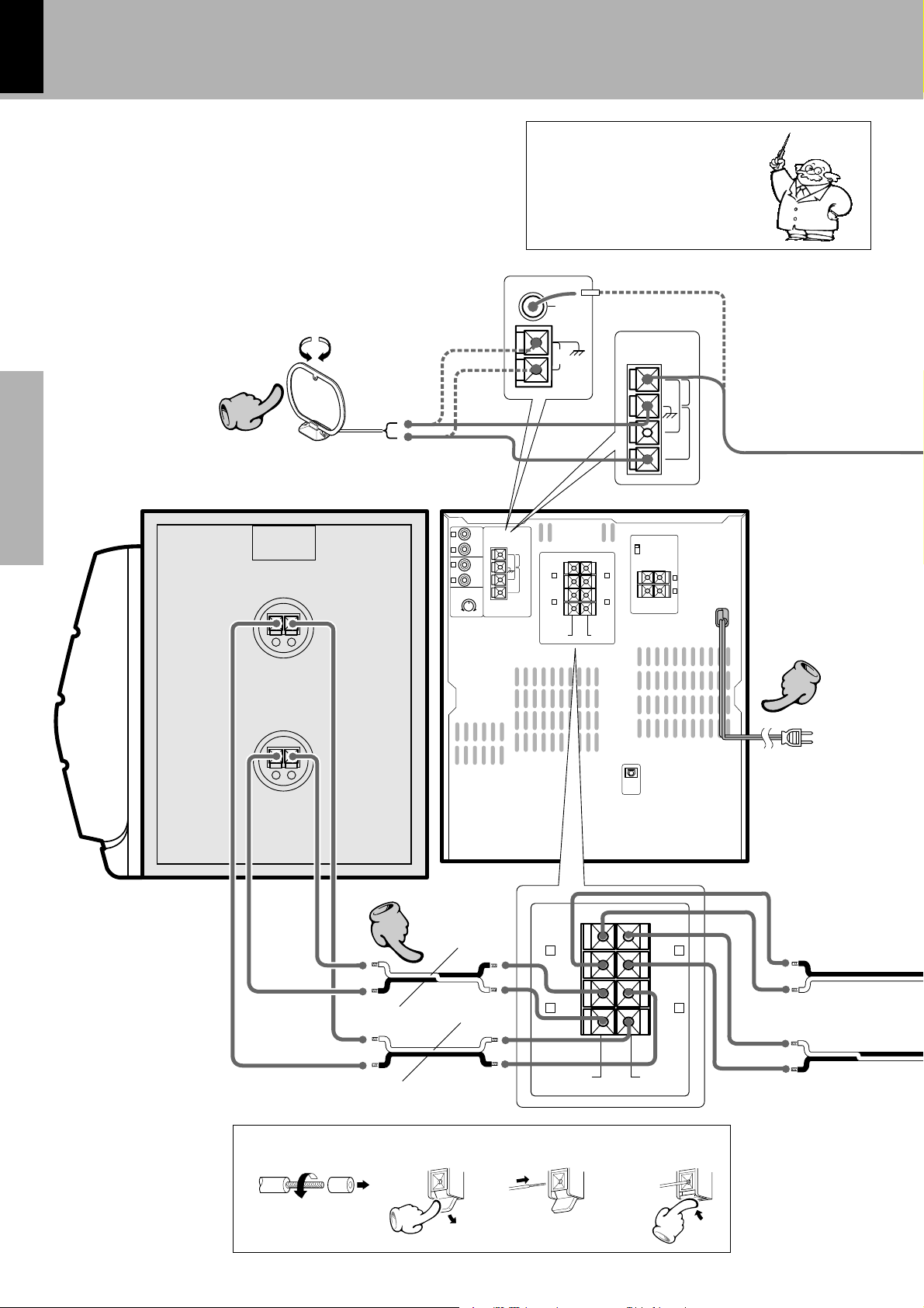
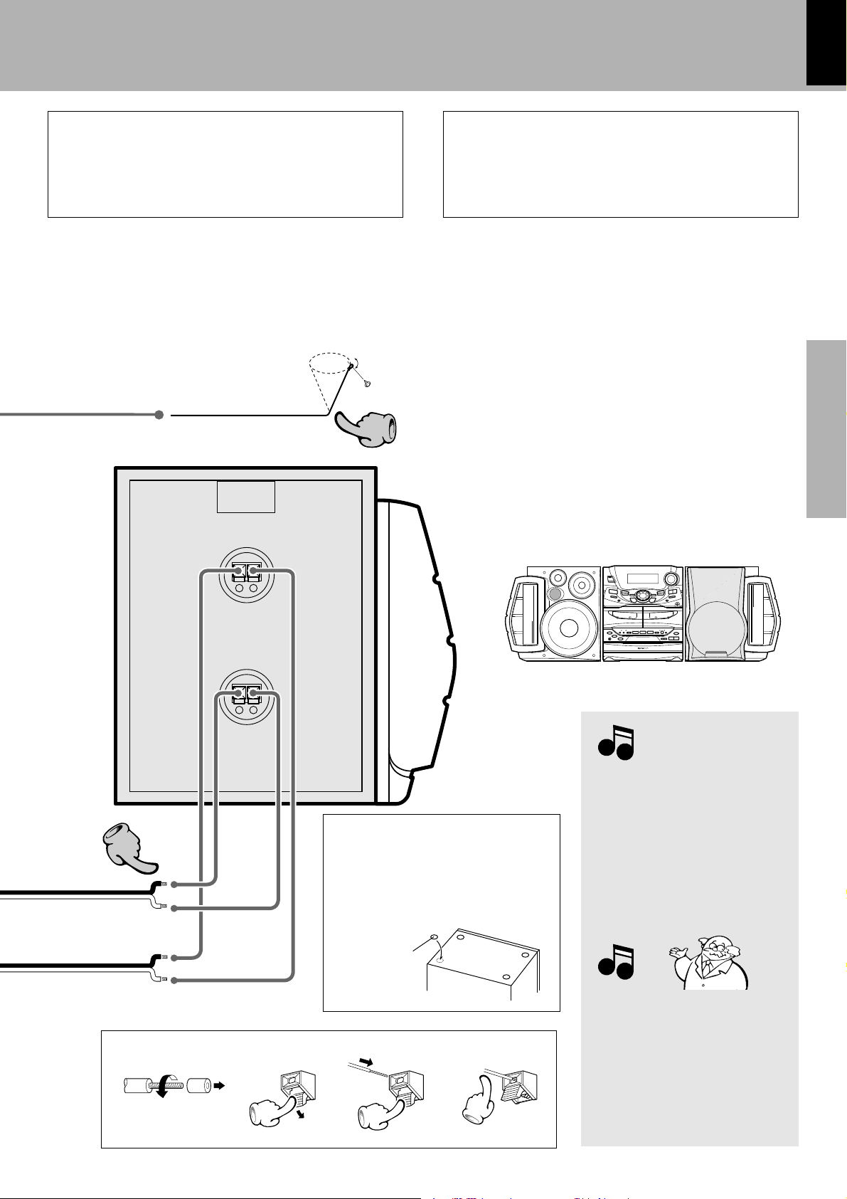
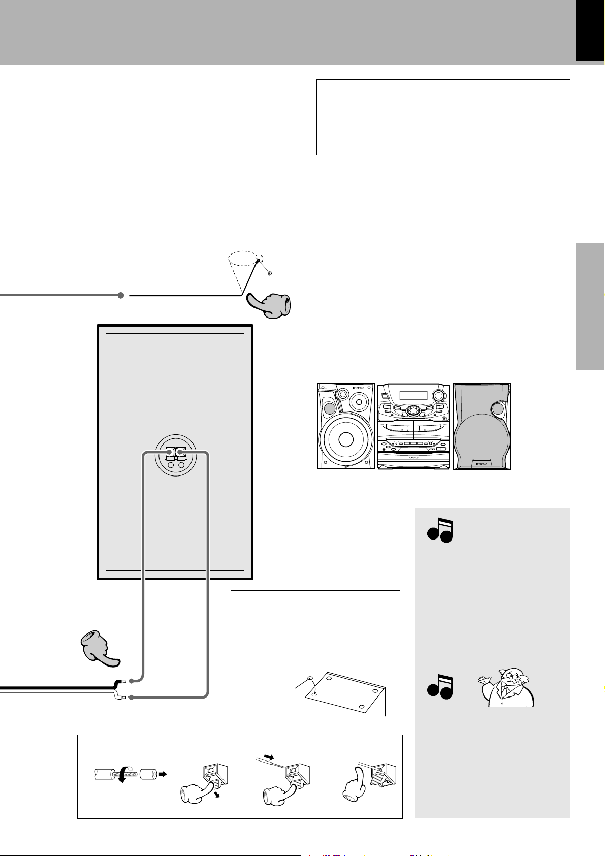
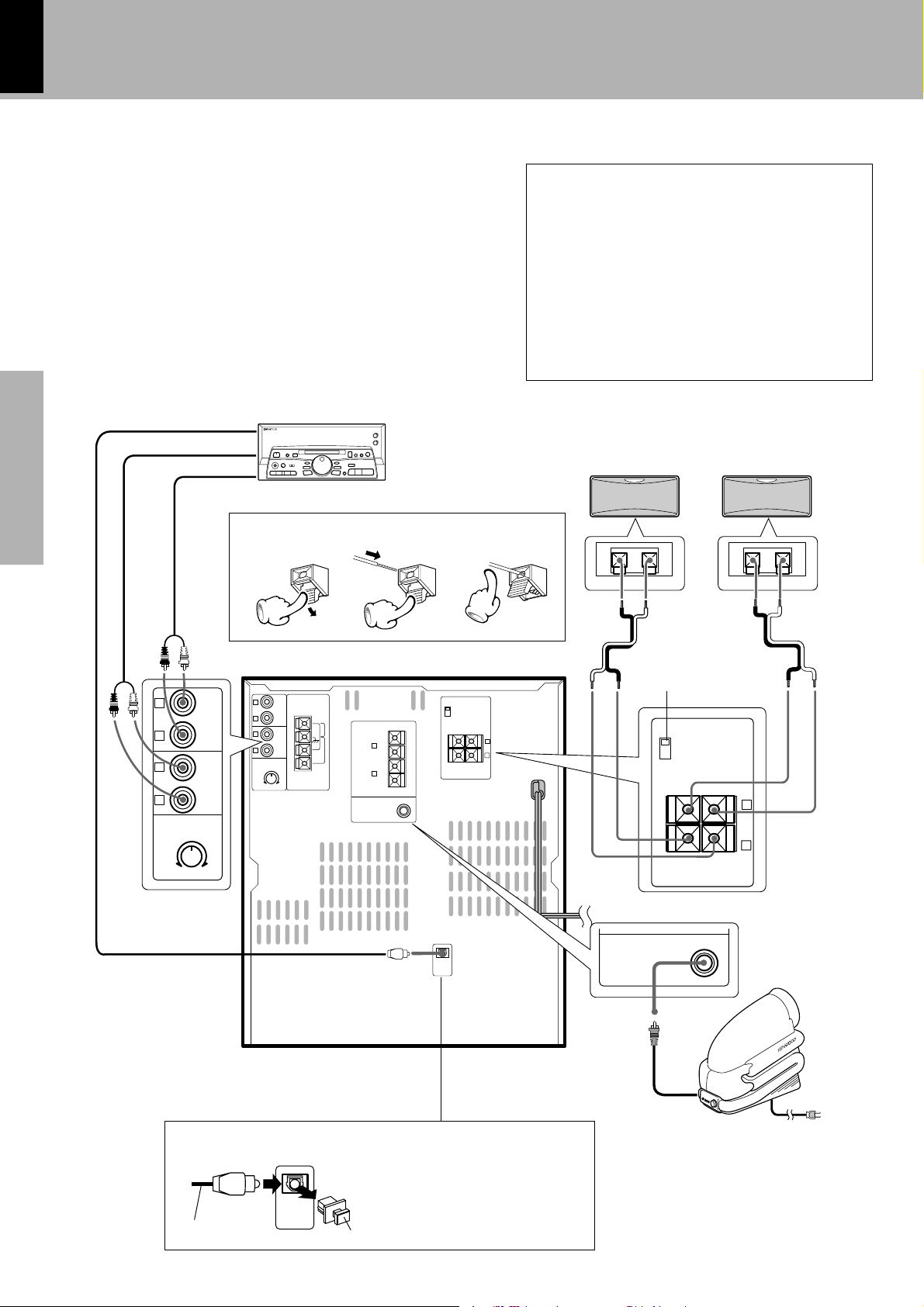
System connection (XD-7...series)
This is the connection method for system and accessories.
Please look carefully at the illustration and connect cor-
rectly in the order of the numbers.
Connection of the System Accessories
Twist
The supplied antenna is for indoor use. Place it as far as
possible from the main system, TV set, speaker cords and
power cord, and set it to a direction which provides the
best reception.
AM loop antenna
To wall AC outlet
Power cord
Main Unit
Speaker cord
3214
Speaker (right)
Red
Black
Black
Blue
Europe and U.K.
Other countries
Malfunction of microcomputer
If operation is not possible or erro-
neous display appears even though
all connections have been made
properly, reset the microcomputer
referring to “In case of difficulty”.
P
GND
L
R
L
R
SUB WOOFER
SPEAKERS
(12-16Ω)
FRONT
SPEAKERS
(6-16Ω)
AUX
OUTPUT
ANTENNA
FM
300Ω
AUX
INPUT
AUX
INPUT
LEVEL
MIN. MAX.
L
R
L
R
R
SURROUND
SURROUND
SPEAKERS
(6-16Ω)
L
+–
–
–
+
+
–
–
+
+
DIGITAL
OUT
OPTICAL
4
4
−
+
−
+
22
33
SUB WOOFER
SPEAKERS
(12-16Ω)
FRONT
SPEAKERS
(6-16Ω)
R
–
–
+
+
–
–
+
+
L
R
L
FM
75Ω
GND
AM
GND
ANTENNA
FM
300Ω
% ON
fi
OFF
FM
75Ω
AM
FM
75Ω
AM
XD-SERIES (En)
7
Preparation section Basic section Application section Knowledge sections
Twist
Speaker Unit
FM indoor antenna
The accessory antenna is for temporary indoor use only. For stable
signal reception we recommend using an outdoor antenna. Remove
the indoor antenna if you connect one outdoors.
System connection (XD-7...series)
Speaker (left)
3214
The external view is variable depending on the model and
marketing destination area.
1 Strip the coating from the tip of cord and twist the
conductor.
2Connect to the antenna terminal.
3Locate the position providing good reception condition.
4Fix the antenna.
WOOFER
SUPER
WOOFER
SUPER
Before connecting the Front
Speakers
Stick the supplied front speaker pads to
the bottom of the front speakers to stabi-
lize the speakers and prevent them from
slipping.
1. In case an associated system compo-
nent is connected, also read the instruc-
tion manual of the component.
2. Never short-circuit the + and – speaker
cords.
3. If the left and right speaker connections
or the + and – polarity are inverted, the
sound will be unnatural with unclear
positioning of musical instruments, etc.
Be sure to connect them without mis-
take.
1. Be sure to insert all connection cords
securely. If their connections are imper-
fect, the sound may not be produced or
noise may interfere.
2. Before plugging or unplugging a con-
nection cord, be sure to unplug the
power cord from the wall AC outlet. If
connection cords are plugged or un-
plugged with the power cord left plugged
in, malfunction or damage may result.
Notes
Notes
Notes
Notes
Speaker cushion
Caution regarding placement
To maintain proper ventilation, be sure to leave a space around
the unit (from the largest outer dimensions including projec-
tions) equal to, or greater than, shown below.
rear panel: 10 cm
Speaker and TV installation
If there is a magnet or other device generating magnetic force
nearby, interaction between the magnet and speaker may cause
color blotching onthe TV. If this happens, move the speaker at
least 20 cm away from the TV set.
+
−
+
−
11
33
XD-SERIES (En)
8
Preparation sectionBasic sectionApplication sectionKnowledge sections
GND
L
R
L
R
SUB WOOFER
SPEAKERS
(12-16Ω)
FRONT
SPEAKERS
(6-16Ω)
AUX
OUTPUT
ANTENNA
FM
300Ω
AUX
INPUT
AUX
INPUT
LEVEL
MIN. MAX.
L
R
L
R
–
–
+
+
–
–
+
+
DIGITAL
OUT
OPTICAL
R
SURROUND
SURROUND
SPEAKERS
(8-16
Ω)
L
+–
% ON
fi
OFF
L
R
L
R
AUX
OUTPUT
AUX
INPUT
AUX
INPUT
LEVEL
MIN. MAX.
R
SURROUND
SURROUND
SPEAKERS
(8-16Ω)
L
+–
% ON
fi
OFF
−+ −+
FM
75Ω
AM
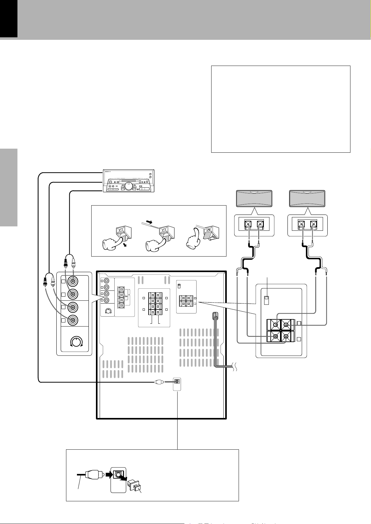
Connect separately sold parts as shown in the figure.
Do not plug the power cord into the power outlet until all
of the required connections have been made.
Connection of Options
(Optional Parts)
System connection (XD-7...series)
In regard to the SURROUND switch
This switch can be used only when the separately sold
surround (rear) speakers are connected. When the switch
is set to ON, surround playback can be enjoyed. When
this switch is set to OFF, normal playback is executed.
÷ Please operate this switch while the power is switched off.
÷ We recommend to keep this switch set to OFF when no
surround (rear) speakers are connected to obtain a better
sound quality.
÷ When the switch is set to OFF, no sound will come from the
surround (rear) speakers.
12 3
Surround (rear) speakers
Surround switch
R
L
(Except for some areas)
DIGITAL OUT jack (OPTICAL)
DIGITAL
OUT
OPTICAL
If necessary, remove the cap and plug
the optical-fiber cable (optional).
Audio output
Cap
Optical-fiber cable
Optical-fiber cable
(Provided with the MD recorder)
Audio input
MD recorder

XD-SERIES (En)
9
Preparation section Basic section Application section Knowledge sections
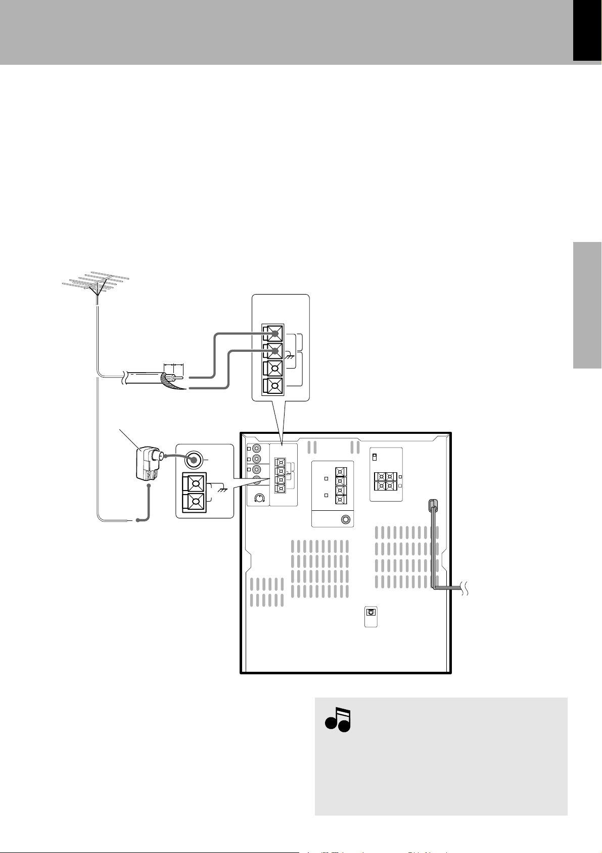
FM outdoor antenna
Lead the 75Ω coaxial cable connected to the FM outdoor antenna
into the room and connect it to the FM 75Ω termimal.
System connection (XD-7...series)
Europe and U.K.
Other countries
Antenna adapter
(optional)
1. All of the optical-fiber cables sold in audio stores cannot always be
used. If the cable you purchased cannot be connected to this unit,
please consult your dealer or KENWOOD distributor.
2. Insert the optical-fiber cable straight into the connector until it clicks.
3.Be sure to attach the protection cap when the connector is not
used.
4.Never band or bundle the optical-fiber cable.
Notes
Notes
GND
L
R
L
R
SUB WOOFER
SPEAKERS
(12-16Ω)
FRONT
SPEAKERS
(6-16Ω)
AUX
OUTPUT
ANTENNA
FM
300Ω
AUX
INPUT
AUX
INPUT
LEVEL
MIN. MAX.
L
R
L
R
–
–
+
+
–
–
+
+
DIGITAL
OUT
OPTICAL
GND
ANTENNA
FM
300Ω
10mm 10mm
FM
75Ω
GND
AM
FM
75Ω
AM
FM
75Ω
AM
R
SURROUND
SURROUND
SPEAKERS
(6-16Ω)
L
+–
% ON
fi
OFF
XD-SERIES (En)
10
Preparation sectionBasic sectionApplication sectionKnowledge sections
GND
L
R
L
R
FRONT
SPEAKERS
(6-16Ω)
SUPER
WOOFER
PRE OUT
AUX
OUTPUT
ANTENNA
FM
300Ω
AUX
INPUT
AUX
INPUT
LEVEL
MIN. MAX.
L
R
SURROUND
–
–
+
+
DIGITAL
OUT
OPTICAL
% ON
fi OFF
FM
75Ω
GND
AM
−
+
22
33
GND
ANTENNA
FM
300Ω
FRONT
SPEAKERS
(6-16Ω)
SUPER
WOOFER
PRE OUT
L
R
–
–
+
+
4
4
FM
75Ω
AM
R
SURROUND
SPEAKERS
(6-16Ω)
L
+–
FM
75Ω
AM
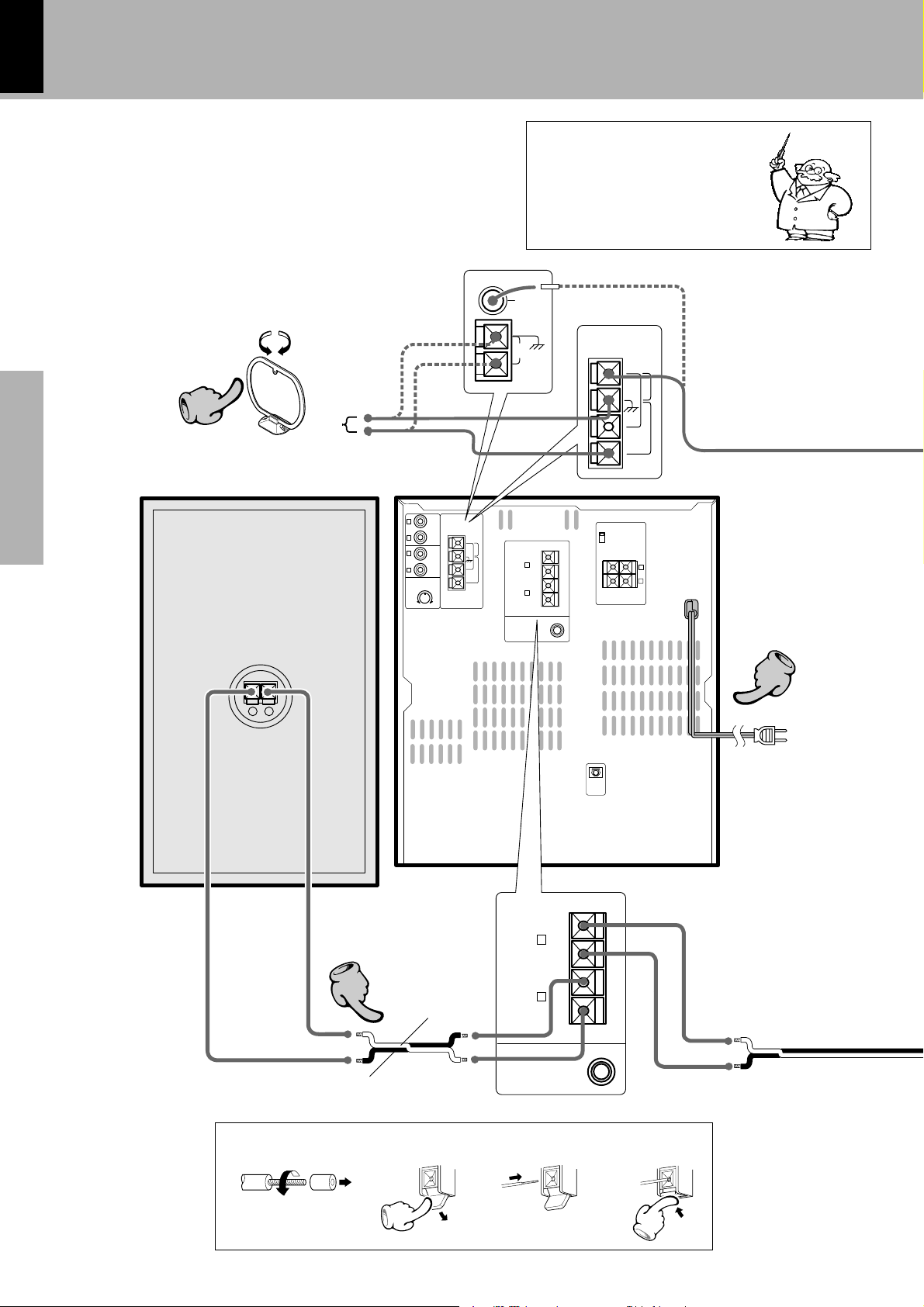
System connection (XD-5...series)
This is the connection method for system and accessories.
Please look carefully at the illustration and connect cor-
rectly in the order of the numbers.
Connection of the System Accessories
Twist
The supplied antenna is for indoor use. Place it as far as
possible from the main system, TV set, speaker cords and
power cord, and set it to a direction which provides the
best reception.
AM loop antenna
To wall AC outlet
Power cord
Main Unit
Speaker cord
3214
Speaker (right)
Red
Black
Europe and U.K.
Other countries
Malfunction of microcomputer
If operation is not possible or erro-
neous display appears even though
all connections have been made
properly, reset the microcomputer
referring to “In case of difficulty”.
P
XD-SERIES (En)
11
Preparation section Basic section Application section Knowledge sections
Twist
Speaker Unit
Caution regarding placement
To maintain proper ventilation, be sure to leave a space around
the unit (from the largest outer dimensions including projec-
tions) equal to, or greater than, shown below.
rear panel: 10 cm
FM indoor antenna
The accessory antenna is for temporary indoor use only. For stable
signal reception we recommend using an outdoor antenna. Remove
the indoor antenna if you connect one outdoors.
System connection (XD-5...series)
Speaker (left)
3214
The external view is variable depending on the model and
marketing destination area.
1 Strip the coating from the tip of cord and twist the
conductor.
2Connect to the antenna terminal.
3Locate the position providing good reception condition.
4Fix the antenna.
BASS REFLEX SPEAKER SYSTEM
BASS REFLEX SPEAKER SYSTEM
Before connecting the Front
Speakers
Stick the supplied front speaker pads to
the bottom of the front speakers to stabi-
lize the speakers and prevent them from
slipping.
1. In case an associated system compo-
nent is connected, also read the instruc-
tion manual of the component.
2. Never short-circuit the + and – speaker
cords.
3. If the left and right speaker connections
or the + and – polarity are inverted, the
sound will be unnatural with unclear
positioning of musical instruments, etc.
Be sure to connect them without mis-
take.
1. Be sure to insert all connection cords
securely. If their connections are imper-
fect, the sound may not be produced or
noise may interfere.
2. Before plugging or unplugging a con-
nection cord, be sure to unplug the
power cord from the wall AC outlet. If
connection cords are plugged or un-
plugged with the power cord left plugged
in, malfunction or damage may result.
Notes
Notes
Notes
Notes
Speaker cushion
−
+
11
33
XD-SERIES (En)
12
Preparation sectionBasic sectionApplication sectionKnowledge sections
Connect separately sold parts as shown in the figure.
Do not plug the power cord into the power outlet until all
of the required connections have been made.
Connection of Options
(Optional Parts)
System connection (XD-5...series)
In regard to the SURROUND switch
This switch can be used only when the separately sold
surround (rear) speakers are connected. When the switch
is set to ON, surround playback can be enjoyed. When
this switch is set to OFF, normal playback is executed.
÷ Please operate this switch while the power is switched off.
÷ We recommend to keep this switch set to OFF when no
surround (rear) speakers are connected to obtain a better
sound quality.
÷ When the switch is set to OFF, no sound will come from the
surround (rear) speakers.
12 3
Surround (rear) speakers
Surround switch
R
L
(Except for some areas)
DIGITAL OUT jack (OPTICAL)
DIGITAL
OUT
OPTICAL
If necessary, remove the cap and plug
the optical-fiber cable (optional).
Audio output
Cap
Optical-fiber cable
Optical-fiber cable
(Provided with the MD recorder)
Audio input
GND
L
R
L
R
FRONT
SPEAKERS
(6-16Ω)
SUPER
WOOFER
PRE OUT
AUX
OUTPUT
ANTENNA
FM
300Ω
AUX
INPUT
AUX
INPUT
LEVEL
MIN. MAX.
L
R
–
–
+
+
DIGITAL
OUT
OPTICAL
−+ −+
L
R
L
R
AUX
OUTPUT
AUX
INPUT
AUX
INPUT
LEVEL
MIN. MAX.
R
SURROUND
SURROUND
SPEAKERS
(8-16Ω)
L
+–
% ON
fi
OFF
R
SURROUND
SURROUND
SPEAKERS
(8-16Ω)
L
+–
% ON
fi
OFF
FM
75Ω
AM
SUPER
WOOFER
PRE OUT
MD recorder
Super woofer
Extremely low sound is played back pow-
erfully. This can be used with any type of
playback.
XD-SERIES (En)
13
Preparation section Basic section Application section Knowledge sections
FM outdoor antenna
Lead the 75Ω coaxial cable connected to the FM outdoor antenna
into the room and connect it to the FM 75Ω termimal.
System connection (XD-5...series)
Europe and U.K.
Antenna adapter
(optional)
1. All of the optical-fiber cables sold in audio stores cannot always be
used. If the cable you purchased cannot be connected to this unit,
please consult your dealer or KENWOOD distributor.
2. Insert the optical-fiber cable straight into the connector until it clicks.
3.Be sure to attach the protection cap when the connector is not
used.
4.Never band or bundle the optical-fiber cable.
Notes
Notes
GND
L
R
L
R
FRONT
SPEAKERS
(6-16Ω)
SUPER
WOOFER
PRE OUT
AUX
OUTPUT
ANTENNA
FM
300Ω
AUX
INPUT
AUX
INPUT
LEVEL
MIN. MAX.
L
R
–
–
+
+
DIGITAL
OUT
OPTICAL
GND
ANTENNA
FM
300Ω
10mm 10mm
FM
75Ω
GND
AM
FM
75Ω
AM
FM
75Ω
AM
R
SURROUND
SURROUND
SPEAKERS
(6-16Ω)
L
+–
% ON
fi
OFF
Other countries
XD-SERIES (En)
14
Preparation sectionBasic sectionApplication sectionKnowledge sections
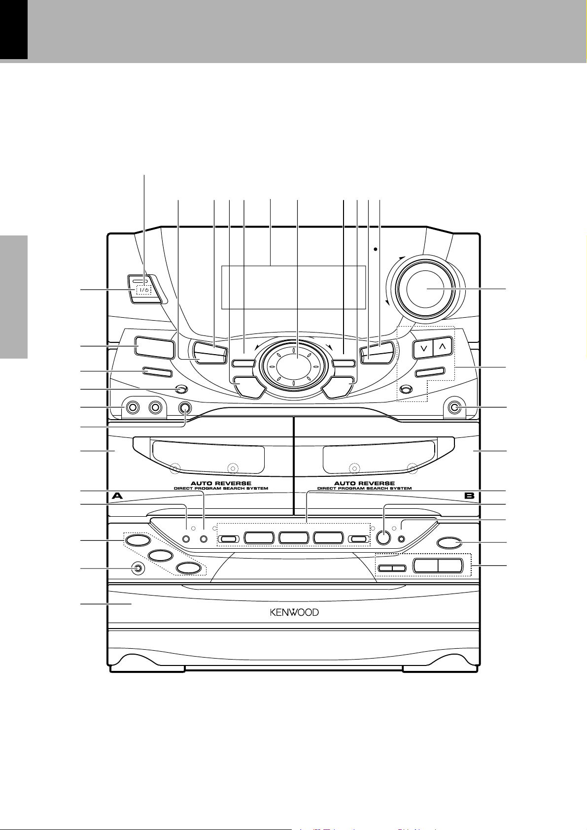
Controls and indicators
Main Unit
7 %9 $@0#8!^
2
¡
™
3
4
5
6
¶
1
)
•
ª
&
*
£
(
º
⁄
§
∞
¢
3
¡
2
1
PLAY
0
PUSH
OPEN
0
PUSH
OPEN
6
¢
7
7
4
DISC SKIP
DISC
1
DISC 2
REV.MODE DOLBY NR
DISC 3
VOLUME
CONTROL
UP
DOWN
SRS 3D
TIMER
DISPLAY
EX. BASS
MODE
/DEMO
ENTER
AUTO
PHONES
SET
MAXMIN
SOUND
MULTI
CONTROL
ON/STANDBY
INPUT
MIC
VOL.
1— MIC —2
DUBBING
TUNING
BAND
CD PGM
MINI HiFi COMPONENT SYSTEM
REC
/PLAY
A/B
REC/ARM
0
SRS ( )
POWER
(For U.S.A. and Canada)

XD-SERIES (En)
15
Preparation section Basic section Application section Knowledge sections
Controls and indicators
Receiver
1 ON/STANDBY ( POWER) key
)
Power ON/OFF switching is executed.
2EX. BASS (Extra bass) key
¡
Switches the extra bass play on and off.
3DISPLAY key
p
Switches the displayed information.
4INPUT key
)
Press to select the input source. When TAPE or CD is selected,
playback starts automatically provided that a tape or disc has already
been loaded.
5MIC 1, MIC 2 terminal (Except for some areas)
E
For connection of a microphone (optional).
6MIC VOL. knob (Except for some areas)
E
At the time of mic mixing , this knob controls the volumes of the
microphones.
7MODE/DEMO key
4¡oW
Used for setting or selection of various modes.
The items which can be selected differ according to the status at that
time.
When power is STANDBY: Switches the demonstration on and
off.
8TIMER key
RI
Used for time adjustment, timer setting, etc.
9SET key
¡
Used for setting of various modes or establishing a selection.
0SOUND key/Indicator
pQ
Used for the equalizer mode setting, etc.
!DISPLAY
^
@MULTI CONTROL jog dial
(
Used for selection of various modes.
#SRS 3D key/Indicator
W
Switches the SRS 3D play on and off.
$ENTER key
¡
Used for entering a selected mode in memory or executing it.
%DUBBING key
‹ti
Used for tape dubbing or CD recording onto tape.
^CD PGM key
›
Used for programming CD tracks.
&VOLUME CONTROL knob
)
This is used for volume adjustment.
*Tuner operation keys
•ª
TUNING keys
Press to select a radio station.
BAND key
Press to switch the receiving band.
AUTO key
Switches the tuning mode.
(PHONES terminal
)
For connection of a headphone (optional).
Cassette deck unit
) A deck cassette holder
Press the area marked
00
00
0 PUSH OPEN to load or eject a tape.
¡DOLBY NR key
∞
Dolby noise reduction ON/OFF switching is executed.
™REV. MODE key
∞
The reverse mode of the deck (both sides, repeated, one side) is
switched.
£B deck cassette holder
Press the area marked
0 0
0 0
0 PUSH OPEN to load or eject a tape.
¢Cassette deck operation keys
¢∞
Play (2 3) keys
Stop (7) key
Fast forward and rewind (1 ¡) keys
∞A/B key
¢¤
Press to select the deck to be operated. Used as the beat cancel key
during recording of AM broadcasting.
§REC/ARM key
⁄‹
Press to start recording. Pressing the key during recording stops it
after leaving a non-recorded space (blank) of about 4 seconds.
CD player unit
¶ DISC SELECTOR key
£
The disc for playback (or recording) is selected.
•DISC SKIP key
£
The disc for playback (or recording) is selected. This is also used for
insertion of a CD to the inside of the disc tray.
ªDisc tray
™
Three discs can be stored.
ºOPEN/CLOSE (0) key
™
The disc tray is opened and closed.
⁄CD operation keys
™£
Play/pause (6) key
Stop (7) key
Skip (4 ¢) keys
XD-SERIES (En)
16
Preparation sectionBasic sectionApplication sectionKnowledge sections
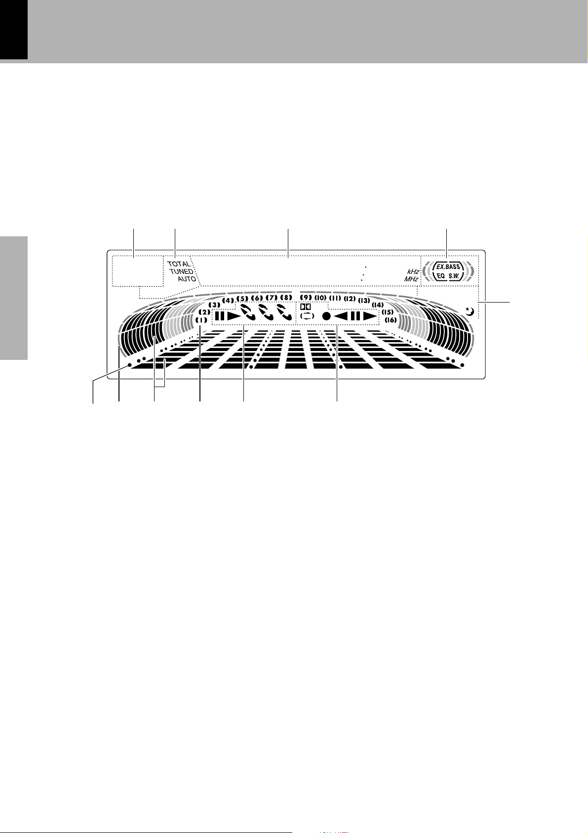
Controls and indicators
Display
1 RDS-related indicators (Provided except for some areas)
2Tuner and applied CD operation indicators
This section contains the indicators of the tuner operations and
applied CD operations.
3Character information display
Displays the input selection, frequency, volume level, etc.
4Tone and sound field-related indicators
5Timer-related indicators
6Cassette deck indicators
This section contains the cassette deck operation indicators. The
indicated information includes the tape reverse mode and tape trans-
port direction.
7CD player indicators
This section displays the CD playback and pause mode information as
well as the disc number being played.
8Track number indicator
Indicates the CD track number being played.
9Spectrum analyzer display
0RUNNING INDICATOR
This indicator rotates according to the operation modes during opera-
tion of the CD player, cassette deck, etc. It also shows the approxi-
mate sound level during volume control.
!Guideline
Blinks during the setting of an item using the jog dial.
(
O.T.T.
P.B.C. STEREO
PROG.
12
TP TA
NEWS INFO.
PTY
R.D.S EON
NR
ECHO
SLEEP
3
12
*
*
*
*
*
*
*
*
*
*
21 3 4
0
6780
5
9!
(The displays given in this manual are approximations only.
They may differ from what actually appears on the display.)
XD-SERIES (En)
17
Preparation section Basic section Application section Knowledge sections
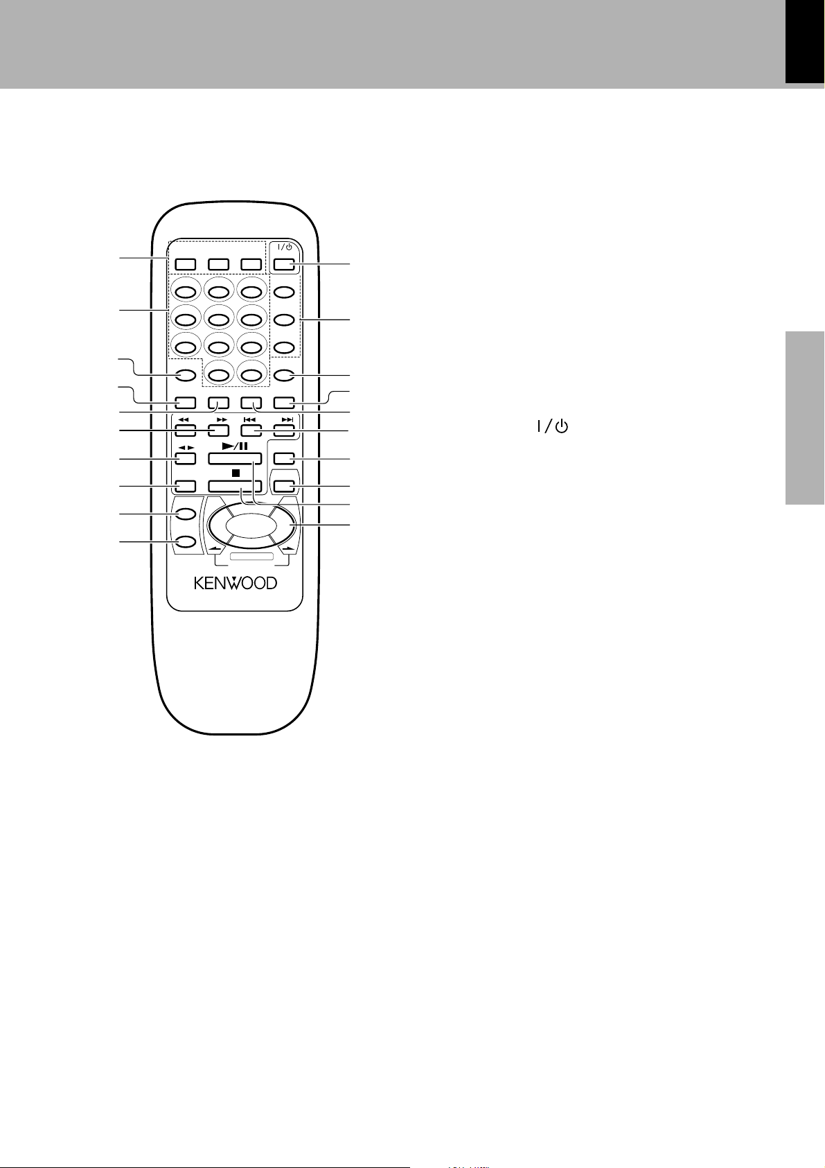
1RDS-related keys (Except for the RC-701)
TA/NEWS/INFO. key
w
Used for automatic reception of transmissions of a certain content.
RDS DISP. key
·
The display contents are switched during reception of RDS broad-
casts.
PTY key
‚
This is used to specify the program type when searching for a station.
Remote control Unit
Controls and indicators
VOLUME
TAPE
SET
ENTER
A/B
CD
TUNING P.CALL
MUTE
MENU
RC-701R
REMOTE CONTROL UNIT
123
0
456
+10
789
DISC SKIP
EX.BASS
SRS 3D
TIME RANDOM REPEAT BAND
EQ ON/OFF
INPUT
RDS DISP. PTY
TA/NEWS
/INFO.
POWER
MULTI CONTROL
2
7
8
9
0
1
3
4
5
6
@
&
^
*
#
!
%
$
)
(
2Numeric keys
£
Used as number keys when the input is CD or TUNER.
3DISC SKIP key
£
4TIME key
™
Press to switch the time information on the CD player unit.
5RANDOM key
°
For CD playback, switching is executed between random playback
and normal playback.
6TUNING (1 ¡) keys (TUNER/CD)
•£
7TAPE play (
2 32 3
2 32 3
2 3) keys
¢
8A/B key
¢¤
9SET key
¡
0ENTER key
¡
!ON/STANDBY ( POWER) key
)
Power ON/OFF switching is executed.
@Tone and sound field-related keys
SRS 3D key
W
EX. BASS key
¡
EQ. ON/OFF key
p
Press to switch the equalizer ON and OFF.
#INPUT key
)
$BAND key
•
%REPEAT key
fl
Used for repeated playback of a CD.
^P.CALL (Preset Call) (4 ¢) keys (TUNER/CD)
Used to recall a preset radio station.
•
During CD playback, press to skip CD tracks.
£
&MUTE key
¡
This is used to mute the sound temporarily.
*MENU key
Used to switch the function of the MULTI CONTROL keys.
The function items that can be selected with the MULTI CONTROL
keys are variable depending on the current operation status.
Items such as CD PGM, DUBBING, SOUND, DISPLAY, TIMER and
MODE are selected using keys ).
(CD play/pause (6) key
Stop (7) key
)MULTI CONTROL/VOLUME keys
¡
The left and right keys have the same functions as the MULTI
CONTROL jog dial on the amplifier/tuner unit.
The top and bottom keys are used to adjust the volume.
)
Model: See left.
Infrared ray system.
Europe and U.K. : RC-701R
Other countries : RC-701
The keys on the remote control unit with the same names as
on the main unit have the same function as the keys on the
main unit.
XD-SERIES (En)
18
Preparation sectionBasic sectionApplication sectionKnowledge sections
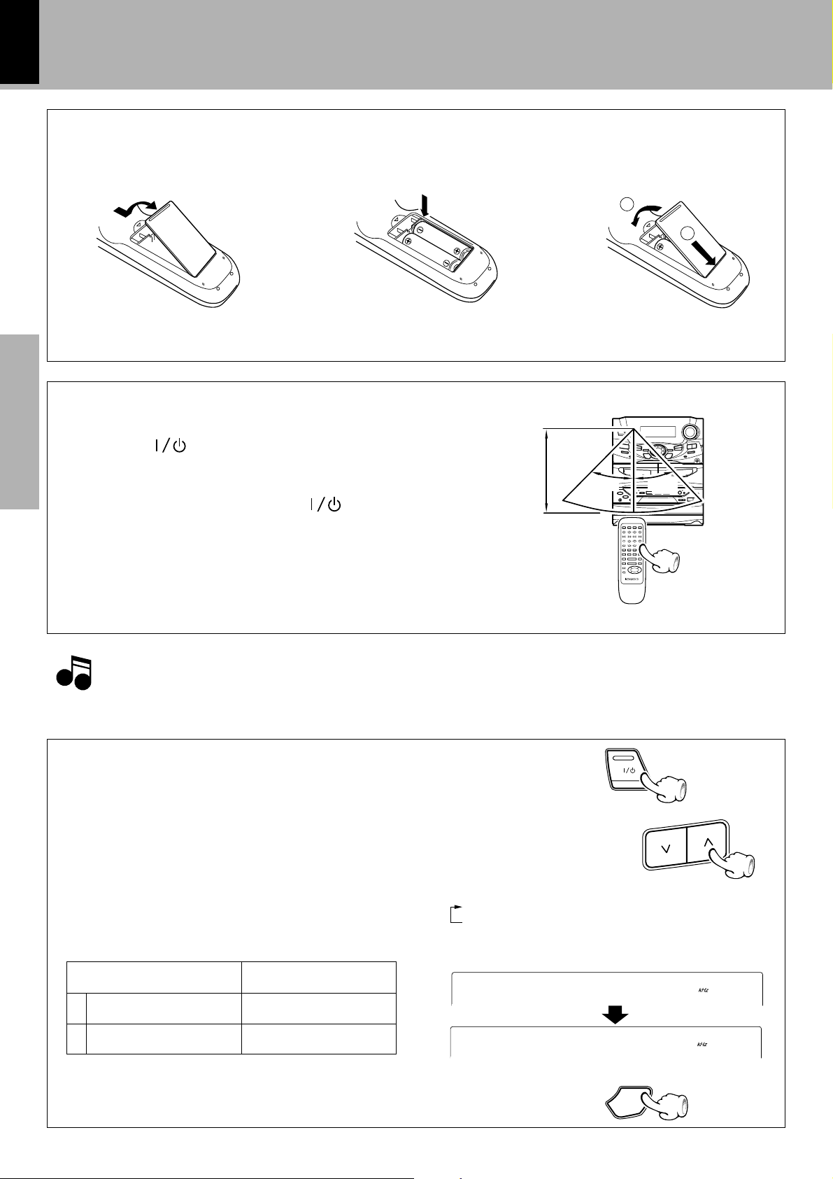
1Turn power off.
2Select the channel space.
Each press switches the space frequency alternately.
1 “FM100/AM10 kHz”....... STEP,
2 “FM 50 /AM 9 kHz”....... STEP,
÷ The “AM” display is variable depending on the model (country or
area), and “MW” may be displayed in some areas.
3Establish the selection.
Operation
Plug the power cord into the mains power outlet and press
the on/standby (
POWER) key of the remote control
unit to turn power ON. After the power has been turned
ON, press the desired key.
To turn power off, press the on/standby (
POWER)
key again. The system enters the standby mode in which
only the time display is lit.
÷ When pressing more than one remote control keys successively,
press the keys securely by leaving an interval of 1 second or more
between keys.
Loading batteries
2 Insert batteries. 3 Close the cover.
1. The provided batteries are intended for use in operation checking, and their service life may be short.
2. When the remote controllable distance becomes short, replace both of the batteries with new ones.
3. If direct sunlight or the light of a high- frequency fluorescent lamp (inverter type, etc.) is incident to the remote sensor, malfunction may occur.
In such a case, change the installation position to avoid malfunction.
1 Remove the cover.
Operation of remote control unit
Notes
Notes
Operating range (approx.)
Remote sensor
÷ Insert two R6 (“AA”-size) batteries following
the polarity indications.
2
1
TUNIN
G
CHANNEL SPACE setting
(Except for the U.S.A., Canada, U.K. Europe and Australia)
CHANNEL
SPACE freq.
Area
1
2
USA, Canada and South
American countries
Other countries
FM : 100 kHz
AM: 10 kHz
FM : 50 kHz
AM: 9 kHz
The space between radio channels has been set to the one that pre-
vails in the area to which the system is shipped. However, if the
current channel space setting does not match the setting in the area
where the system is to be used, for instance when you move from
area 1 or area 2 shown in the following table or vice versa, proper
reception of AM/FM (SW/MW/FM) broadcasts cannot be expected.
In this case, change the channel space setting in accordance with
your area by referring to the following table.
ON/STANDBY
0
/
A
M
1
0
0
1
M
F
0
/
A
M
9
5
M
F
ENTER
30
˚
6m
30
˚
XD-SERIES (En)
19
Preparation section Basic section Application section Knowledge sections
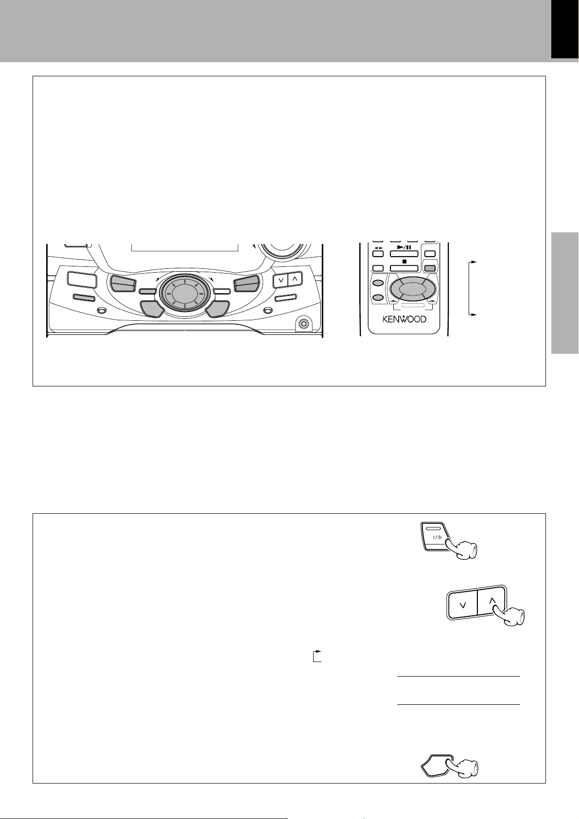
1Turn power off.
2Press the TUNING (u) key.
Each press switches the reception mode alternately.
1 POLAR system
2 PILOT TONE system
3Establish the selection.
TUNIN
G
Reception mode switching of FM broadcast
When you want to receive an FM broadcast in PILOT TONE mode,
changing the setting as follows.
ON/STANDBY
ENTER
VOLUME
TAPE
SET
ENTER
A/B
CD
MUTE
MENU
RC-701R
REMOTE CONTROL UNIT
MULTI CONTROL
DOWN
SRS 3D
TIMER
DISPLAY
EX. BASS
MODE
/DEMO
ENTER
AUTO
PHONES
SET
SOUND
MULTI
CONTROL
ON/STANDBY
INPUT
DUBBING
TUNING
BAND
CD PGM
R
A
L
O
P
T
O
L
I
P
MULTI CONTROL jog dial
The MULTI CONTROL jog dial (or the MULTI CONTROL keys on the remote control unit) allows you to set (or enter) a variety
of functions with an easy operation.
The mode for setting (using) MULTI CONTROL is initiated when any of
the CD PGM, DUBBING, SOUND, DISPLAY, TIMER and MODE/DEMO
keys is pressed.
In the setting mode, select the operation mode with the MULTI CON-
TROL jog dial and press the SET and/or ENTER key(s) to set, establish,
enter or execute the function.
(The ENTER key is always pressed at the end.)
With the remote control unit, pressing the
MENU key makes it possible to select the
same items as those available on the main
unit using the MULTI CONTROL keys.
÷ During the setting of an item (while the guideline is blinking), other keys are defeated except for the basic control keys such as the VOLUME
CONTROL and ON/STANDBY keys.
÷ To cancel the mode for setting (using) MULTI CONTROL, read the description of each item in this manual.
CD PGM
DUBBING
SOUND
DISPLAY
TIMER
MODE
For Russia
XD-SERIES (En)
20
Preparation sectionBasic sectionApplication sectionKnowledge sections
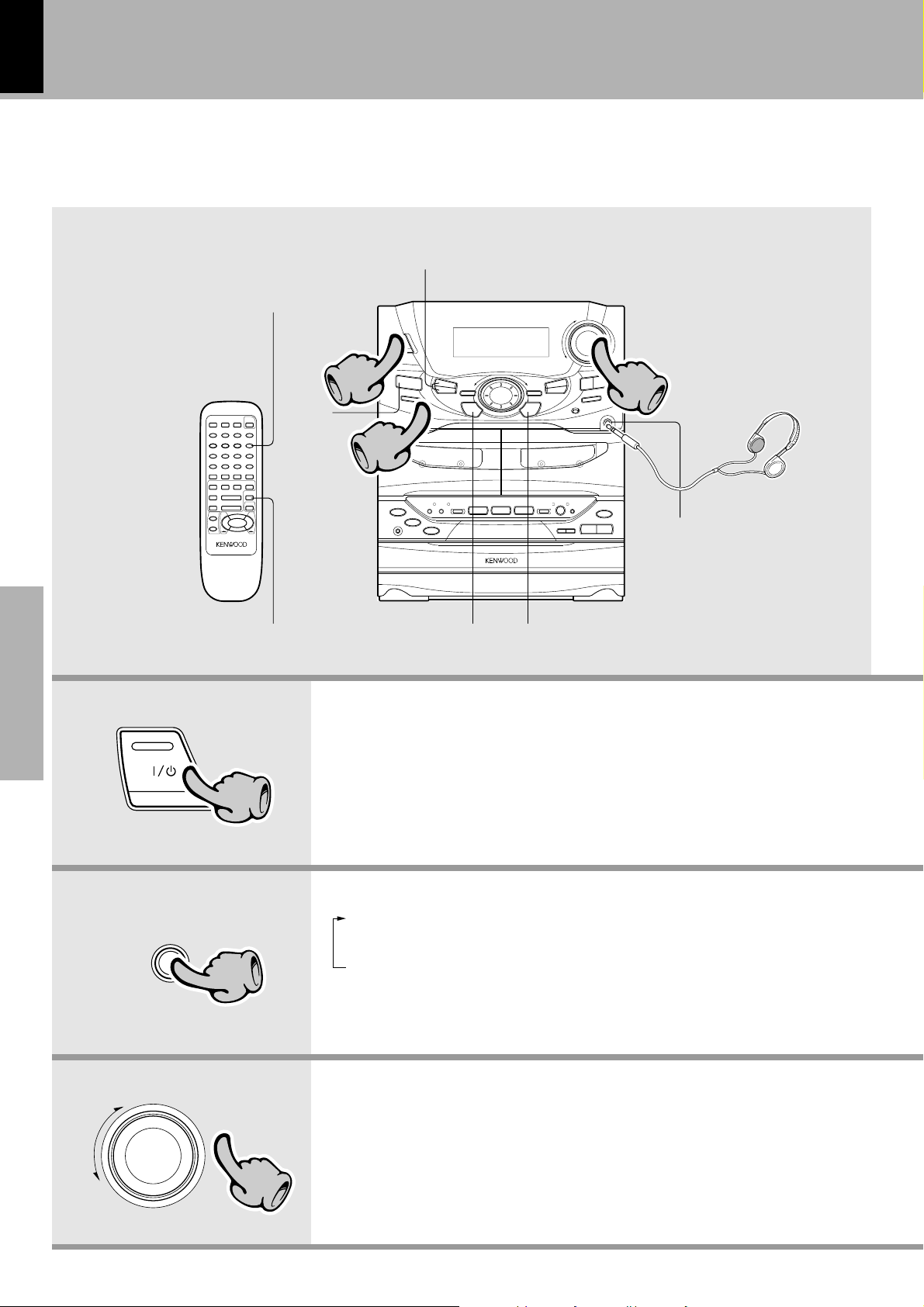
Let's put out some sound
÷ The display part becomes dark when the power
is switched OFF. (DIMMER function)
÷ Quick turning produces a larger change amount.
(AI VOLUME control function)
÷ The display shows a reference value.
The power can also be turned ON by pressing the play key of the CD player, the
play key of the cassette deck or the BAND key of the tuner.
When the ON/STANDBY key is pressed while the power is ON, the power will be
switched OFF.
Basic use method
Muting the sound temporarily
Listening through headphones
÷ When you select the AUX input, be also sure to
read the instruction manual of the component
connected to the AUX input jacks.
(AUX INPUT LEVEL adjustment
o)
÷ When CD or TAPE is selected, playback will
start when a disc or a tape already has been
inserted into deck B.
3. Volume adjustment
2. Selecting the desired output
1. Switching the power ON (OFF)
33
11
22
SET ENTER
EX.BASS
Bass and treble compensation
TIMER,
MODE/DEMO
Insert the headphone plug into
the PHONES jack.
÷ The sounds from all speakers are
cut off.
ON/STANDBY
11
IN
PUT
22
33
VOLUME
CONTROL
UP
DOWN
TUNER (Radio) •
CD ™
TAPE ¢
AUX (External input) 8@
Loading...