


AUDIO VIDEO SURROUND RECEIVER
VRS-7100
INSTRUCTION MANUAL
KENWOOD CORPORATION
Quick Start Reference
Please read the following pages so that you can enjoy the surround sound at the best condition.
(These pages give shortcut explanations on how to connect the speaker system to the receiver, set up the speakers and play a source.)
"Let's play DVD video software" )¡, ™£
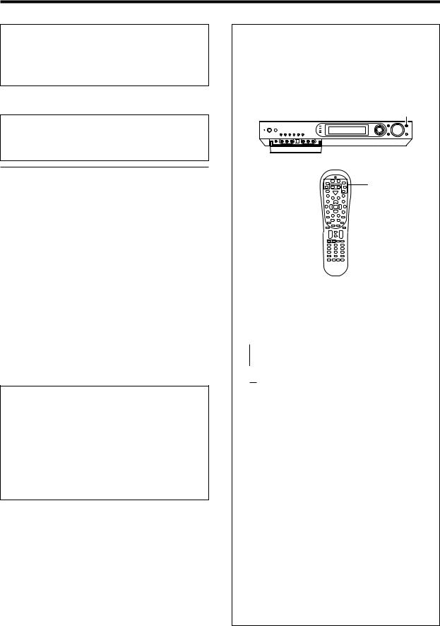
About the supplied remote control
Compared to standard remote controls, the remote control supplied with this receiver has several operation modes. These modes enable the remote control to control other audio/video components. In order to effectively use the remote control it is important to read the operating instructions and obtain a proper understanding of the remote control and how to switch its operation modes (etc.).
Using the remote control without completely understanding its design and how to switch the operation modes may result in incorrect operations.
|
|
|
|
|
|
|
|
|
|
|
|
|
|
|
|
|
|
|
|
|
|
|
|
|
|
|
|
|
|
|
|
|
|
|
|
|
|
|
|
|
|
|
|
|
|
|
|
|
|
|
|
|
|
|
|
|
|
|
|
|
|
|
|
|
|
|
|
|
|
B60-5462-10 02 MA ( K, P, E, X ) |
0312 |
|
|
|
|
|
|||||||
Before applying power
Caution : Read this page carefully to ensure safe operation.
Units are designed for operation as follows.
U.S.A. and Canada ........................................... |
AC 120 V only |
Europe ............................................................... |
AC 230 V only |
Australia ........................................................... |
AC 240 V only |
|
|
Safety precautions
WARNING : TO PREVENT FIRE OR ELECTRIC SHOCK, DO NOT EXPOSE THIS APPLIANCE TO RAIN OR MOISTURE.
CAUTION
RISK OF ELECTRIC SHOCK
DO NOT OPEN
CAUTION: TO REDUCE THE RISK OF ELECTRIC SHOCK, DO NOT REMOVE COVER (OR BACK). NO USER-SERVICEABLE PARTS INSIDE. REFER SERVICING TO QUALIFIED SERVICE PERSONNEL.
THE LIGHTNING FLASH WITH ARROWHEAD SYMBOL, WITHIN AN EQUILATERAL TRIANGLE, IS INTENDED TO ALERT THE USER TO THE PRESENCE OF UNINSULATED “DANGEROUS VOLTAGE” WITHIN THE PRODUCT’S ENCLOSURE THAT MAY BE OF SUFFICIENT MAGNITUDE TO CONSTITUTE A RISK OF ELECTRIC SHOCK TO PERSONS.
THE EXCLAMATION POINT WITHIN AN EQUILATERAL TRIANGLE IS INTENDED TO ALERT THE USER TO THE PRESENCE OF IMPORTANT OPERATING AND MAINTENANCE (SERVICING) INSTRUCTIONS IN THE LITERATURE ACCOMPANYING THE APPLIANCE.
2 EN
Before applying the power
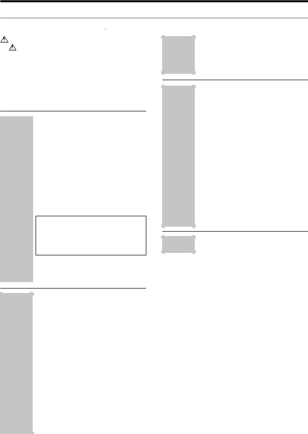
How to use this manual
This manual is divided into four sections, Preparations, Operations, Remote Control,and Additional Information.
Preparations
Shows you how to connect your audio and video components to the receiver and prepare the surround processor. Since this receiver works with all your audio and video components, we will guide you in setting up your system to be as easy as possible.
Operations
Shows you how to operate the various functions available on the receiver.
Remote Control
Shows you how to operate other components using the remote control, as well as a detailed explanation of all remote control operations.Once you have registered your components with the proper setup codes,you ’ll be able to operate both this receiver and your other AV components (TV, VCR, DVD player, CD player, etc.)using the remote control supplied with this receiver.
Additional Information
Shows you additional information such as "In case of difficulty" (trouble shooting) and "Specifications".
Maintenance of the unit
When the front panel or case becomes dirty, wipe with a soft, dry cloth. Do not use thinner, benzine, alcohol, etc. for these agents may cause discoloration.
In regard to contact cleane
Do not use contact cleaners because it could cause a malfunction. Be specially careful not to use contact cleaners containing oil, for they may deform the plastic component.
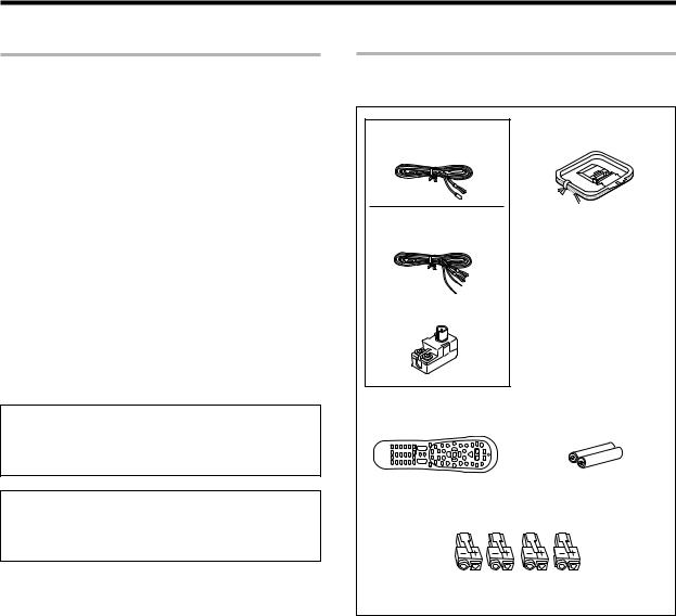
Unpacking
Unpack the unit carefully and make sure that all the accessories are present.
(For the U.S.A. and Canada) |
AM loop antenna (1) |
|
FM indoor antenna (1) |
||
|
||
(For Europe and Australia) |
|
|
FM indoor antenna (1) |
|
|
Antenna adaptor (1) |
|
|
Remote control unit |
Batteries (R6/AA) |
|
(1) |
(2) |
|
Speaker cord connectors |
||
|
(4) |
|
For Europe and Australia only |
||
If any accessories are missing, or if the unit is damaged or fails to operate, notify your dealer immediately. If the unit was shipped to you directly, notify your shipper immediately. Kenwood recommends that you retain the original carton and packing materials in case you need to move or ship the unit in the future.
Keep this manual handy for future reference.
3 EN

Before applying the power
Special features
True home theater sound ‡~ ·
This receiver incorporates a wide variety of surround modes to bring you maximum enjoyment from your video software. Select a surround mode according to your equipment or the software you are going to play and enjoy!
÷Dolby Digital EX
÷Dolby PRO LOGIC IIx, Dolby PRO LOGIC II
÷Dolby Digital
÷DTS-ES
÷DTS NEO:6
÷DTS 96/24
÷DTS
÷DSP Mode
÷Dolby Virtual Speaker
÷Dolby Headphone
GAME mode function ¶
When you connect a game machine to the GAME jacks on the front panel, the input selector of the receiver switches automatically to "GAME" and the optimum sound field for enjoying games is set.
This feature improves your convenience in playing video games.
DUAL SOURCE function º
While you enjoy audio listening through the speakers, another person can enjoy another source (audio + video) through headphones by connecting the source to the GAME, FRONT AUX jacks.
ACTIVE EQ ⁄
ACTIVE EQ mode will produce a more dynamic sound quality in any condition.You can enjoy a more impressive sound effect when ACTIVE EQ is turned on during Dolby Digital and DTS playback.
Remote control t
In addition to the basic receiver, the remote control supplied with this receiver can also operate almost all of your remote controllable audio and video components. Just follow the simple setup procedure to register the components you have connected.
RDS (Radio Data System) tuner (For Europe) fi
The receiver is equipped with an RDS tuner that provides several convenient tuning functions: RDS Auto Memory, to automatically preset up to 40 RDS stations broadcasting different programs; station name display, to show you the name of the current broadcast station; and PTY search to let you tune stations by program type.
PTY (Program TYpe) search (For Europe) fl
Tune the stations by specifying the type of program you want to hear.
4 EN
Before applying the power
Contents
Caution : Read the pages marked  carefully to ensure safe operation.
Before applying power ........................................... |
2 |
|
Safety precautions ............................................... |
2 |
|
How to use this manual ............................................. |
3 |
|
Unpacking |
.................................................................. |
3 |
Special features ......................................................... |
4 |
|
Contents .................................................................... |
|
5 |
Names and functions of parts...................................... |
6 |
|
Main unit .................................................................... |
|
6 |
Remote control unit ................................................... |
7 |
|
|
Setting up the system ............................ |
8 |
|
Connecting a DVD player ............... |
9 |
|
Connecting video components, |
|
|
audio components ........................ |
10 |
|
Digital connections ....................... |
12 |
|
Connecting the speakers ............. |
13 |
|
Connecting the speaker terminals ... |
15 |
|
PRE OUT connections .................. |
16 |
|
Connecting to the GAME jacks / |
|
|
FRONT AUX jacks ........................ |
17 |
Preparations |
Connecting the antennas ............. |
18 |
|
Preparing the remote control ....... |
19 |
|
Let’s play DVD video software |
|
|
(For U.S.A. and Canada) ................... |
20 |
|
Let’s play DVD video software |
|
|
(For Europe and Australia) .............. |
22 |
|
Preparing for playback ......................... |
24 |
|
Speaker settings .......................... |
24 |
|
Re-assignment of rear panel jacks ... |
28 |
|
Normal playback ................................... |
29 |
|
Listening to a source component ... |
29 |
|
Listening with headphones .......... |
30 |
|
Adjusting the sound ..................... |
30 |
|
Recording .............................................. |
32 |
|
Analog sources ............................. |
32 |
|
Digital sources .............................. |
32 |
|
Listening to radio broadcasts .............. |
33 |
|
Tuning (non-RDS) radio stations ... |
33 |
Operations |
|
|
|
Presetting radio stations .............. |
33 |
|
Receiving preset stations ............. |
34 |
|
Receiving preset stations in order |
|
|
(P.CALL) ........................................ |
34 |
|
Using RDS (Radio Data System) |
|
|
(For Europe only) .................................. |
35 |
|
Using the RDS Disp. (Display) key ... |
35 |
|
Tuning by Program TYpe |
|
|
(PTY search) ................................. |
36 |
|
Ambience effects .................................. |
37 |
|
Surround modes ........................... |
37 |
Operations |
Virtual modes ............................... |
39 |
|
Surround play ............................... |
40 |
|
Convenient functions ........................... |
42 |
|
Basic remote control operations for |
|
|
other components ................................ |
45 |
|
Registering setup codes for other |
|
|
components ................................. |
45 |
|
Searching for your code ............... |
45 |
|
Checking the codes ...................... |
46 |
|
Re-assigning device keys ............. |
46 |
|
Operating other components ....... |
46 |
Remote |
Clearing all of the settings registered or |
|
Control |
stored in the remote control unit ..... |
46 |
|
Setup code chart (RC-R0730) (For |
|
|
U.S.A., Canada and Australia) ...... |
47 |
|
Setup code chart (RC-R0730E) (For |
|
|
Europe) ......................................... |
51 |
|
DVD player , MD recorder CD player |
|
|
& TV operations ........................... |
58 |
|
VCR , Satellite receiver & Cable con- |
|
|
verter operations ......................... |
59 |
Additional |
In case of difficulty................................ |
60 |
Information |
Specifications ........................................ |
62 |
5 EN
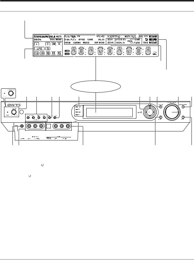
Names and functions of parts
Main unit
Input mode indicators |
|
|
|
|
ACTIVE EQ indicator, |
|||||||||
CLIP indicator |
|
|
|
|
DUAL SOURCE Input indicator, |
|||||||||
|
|
|
|
|
|
|
|
|
|
|
||||
|
MUTE indicator |
Listen mode indicators |
96 kHz fs indicator |
|||||||||||
|
|
|
|
|
||||||||||
|
|
|
|
|
|
|
|
|
|
|
|
|
|
|
|
|
|
|
|
|
|
|
|
|
|
|
|
|
|
|
|
|
|
|
|
|
|
|
|
|
|
|
|
|
|
|
|
|
|
|
|
|
|
|
|
|
|
|
|
Speaker selection indicators, |
|
|
|
|
|
|
|
|
|
|
||||||||||
Input channel indicators (The Input channel |
Frequency |
display, |
||||||||||||||||||
indicators lights up to indicate the channels |
Input display, Preset |
|||||||||||||||||||
contained in the input signal. The "S" indicator |
channel display, |
|||||||||||||||||||
lights when the surround component consists |
Listen mode display |
|||||||||||||||||||
of a single channel.) |
|
|
|
|
|
|
|
|
|
|
|
|
||||||||
For Europe and Australia |
|
|
|
|
|
|
|
|
|
Display |
||||||||||
|
|
|
|
|
|
|
|
|
|
|
|
|
|
|
|
|
|
|
|
|
1 |
|
2 |
|
3 |
4 |
5 |
||||||||||||||
|
|
|
|
|
|
|
|
|
|
|
|
|
|
|
|
|
|
|
|
|
|
|
|
|
|
|
|
|
|
|
|
|
|
|
|
|
|
|
|
|
|
|
|
|
|
|
|
|
|
|
|
|
|
|
|
|
|
|
|
|
|
|
|
|
|
|
|
|
|
|
|
|
|
|
|
|
|
|
|
|
|
|
|
|
|
|
|
|
|
|
|
|
|
|
|
|
|
|
|
|
|
|
|
|
|
|
|
|
|
|
|
|
|
|
|
|
|
|
|
|
|
|
|
|
|
|
|
|
|
|
|
|
|
|
|
|
|
|
|
|
|
|
|
|
|
|
|
|
|
|
|
|
|
|
|
|
|
|
|
|
|
|
|
|
|
|
|
|
|
|
|
|
|
|
|
|
|
|
|
|
|
|
|
|
|
|
|
|
|
|
|
|
|
|
|
|
|
|
|
|
|
|
|
|
|
|
|
|
|
|
|
|
|
|
|
|
|
|
|
|
|
|
|
|
|
|
|
|
|
|
Dolby Headphone mode indicator,
Dolby Virtual Speaker mode indicator
AUTO indicator, ST. indicator,
TUNED indicator, Sleep Timer indicator,
TONE indicator
For Europe Only :
RDS indicator, PTY indicator
6 |
7 |
8 |
9 |
0 |
% $ View when the GAME/ FRONT AUX jack # |
|
|
@ |
|
! |
||||||
cover is open. |
|
|
|
|
|
|
|
||||
1 (For the U.S.A. and Canada) |
|
5 Dolby D indicator |
‚ |
8 |
ACTIVE EQ key |
|
⁄ |
||||
POWER ON/STANDBY |
|
key |
¢ |
Lights when the receiver is in the Dolby |
|
Use to select ACTIVE EQ's setting. |
|||||
|
|
||||||||||
Use to turn the power ON/STANDBY. |
Digital mode. |
|
9 |
VOLUME CONTROL knob |
ª |
||||||
(For Europe and Australia) |
|
DTS indicator |
‚ |
|
Use to adjust the receiver volume. |
||||||
ON/STANDBY |
|
key |
¢ |
Lights when the receiver is in the DTS mode. |
0 |
INPUT SELECTOR key |
ª |
||||
|
|||||||||||
Use to turn the power ON/STANDBY. |
Dolby H indicator |
· |
|
Use to select input sources. |
|
||||||
STANDBY indicator |
|
Lights when the Dolby H mode is ON. |
! SETUP key |
¡£¤ |
|||||||
Lights when the power is in the standby |
DUAL SRC indicator |
º |
|
Use to select the speakers'settings etc. |
|||||||
mode. |
|
Lights when the DUAL SOURCE mode is |
|
Use to select the REC MODE. |
|
||||||
2 DUAL SOURCE VOLUME 5/∞ keys |
ON. |
|
@ LISTEN MODE key |
|
‚ |
||||||
|
|
|
|
|
º 6 Joystick |
|
|
Use to select the listening mode. |
|||
Use to adjust the volume in the DUAL |
MULTI CONTROL % / fi |
# GAME jacks |
&¶º |
||||||||
SOURCE mode. |
|
|
¡£‹ $ FRONT AUX jacks |
|
&º |
||||||
DUAL SOURCE INPUT key |
º |
Use to control a variety of settings. Use to |
% PHONES jack |
|
º |
||||||
Use to select the input for the DUAL SOURCE |
tuning of radio broadcasting. |
|
Use for headphone listening. |
|
|||||||
mode. |
|
MULTI CONTROL @ / # |
|
|
|
|
|||||
DUAL SOURCE ON/OFF key |
º |
|
¡£› |
|
|
|
|
||||
Use to switch the DUAL SOURCE mode ON/ |
Use to control a variety of settings. Use to |
|
|
|
|
||||||
OFF. |
|
selection of preset radio stations. |
|
|
|
|
|||||
3 BAND key |
‹ |
ENTER |
¡£‹ |
|
|
|
|
||||
Use to select the broadcast band. |
|
Use to control a variety of settings. Use to |
|
|
|
|
|||||
4 AUTO/MONO key |
‹ |
presetting of radio stations. |
|
|
|
|
|||||
Use to select the auto or manual tuning |
7 MULTI CH indicator |
‚ |
|
|
|
|
|||||
mode. |
|
Lights during multi-channel playback. |
|
|
|
|
|||||
Standby mode
While the standby indicator is lit, a small amount of power is supplied to the system to back up the memory. This is called standby mode. Under the condition, the system can be turned ON by the remote control unit.
6 EN
Names and functions of parts
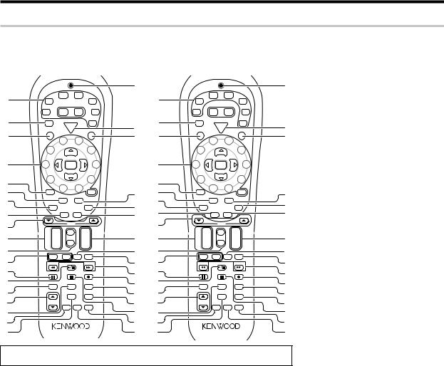
Remote control unit
This remote control unit can be use not only for Kenwood products but also for other non-Kenwood products by setting the appropriate manufacturer’s setup codes. u
For the U.S.A., Canada and Australia: RC-R0730 |
For Europe : RC-R0730E |
1
2
3
4
5
6
7
8
9
0
!
@
#
$
%
^
&
*
(
|
TUNER |
DVD |
|
|
|
|
|
|
VID1 |
|
|
|
|
AUX |
|||
VID2 |
Net |
M.Card |
|
F.AUX |
||||
Mode |
Mode |
|
|
|||||
|
|
|
|
|
|
|||
RCV |
POWER |
|
|
Game |
||||
Mode |
|
|
||||||
|
|
|
|
|
||||
|
P |
RCVR |
|
|
|
Po |
|
|
C |
|
|
|
|
|
|||
o |
|
|
|
V |
|
w |
||
R |
w |
|
|
|
|
|
e |
|
e |
|
|
|
T |
|
|
r |
|
S |
r |
|
|
|
|
|
|
|
|
|
4 |
5 |
|
|
|
|
|
|
3 |
Multi |
|
|
|
6 |
|
|
|
|
|
|
|
|
|
|
|
2 |
P. Call |
Enter |
Call .P |
|
|
|
7 |
|
|
1 |
Multi |
|
|
|
8 |
|
|
|
|
|
|
|
|
|
||
+100 |
0 |
9 |
|
+ 10 |
|
|||
|
|
|
|
|||||
TV Mute |
|
Sleep |
|
|
|
|
||
|
Input |
Menu |
|
|
|
|
||
|
Mode |
|
|
|
|
|||
|
Audio |
|
Guide |
|
Subtitle |
|
|
|
|
|
|
|
|
|
|
|
|
|
|
Angle |
OSD |
|
|
|
|
|
|
|
Page |
|
|
|
|
|
|
¢ |
+ |
Mute |
|
|
+ |
|
|
|
|
CH |
|
|
VOL |
|
|
|
|
|
– |
Sound |
|
|
– |
|
|
|
4 |
|
|
|
|
|
|
||
|
– VOLTV |
+ |
TV Input |
|
TV |
|
|
|
|
Tune – |
Band |
|
|
Tune + |
|
|
|
Dimmer |
Auto |
|
|
Top Menu |
|
|||
|
Exit |
|
|
|
Setup |
|
|
|
|
|
|
|
Input Sel. |
|
|||
|
Retern |
Info |
|
|
Disk Sel. |
|
|
|
|
|
|
|
|
Last |
|
|
|
|
|
Active |
|
Disc Skip |
|
|
||
|
|
EQ |
|
|
|
|
||
Listen Mode |
|
|
|
|
|
|
|
|
|
|
Dolby |
Stereo |
|
Remote |
|
|
|
|
|
Virtual |
|
Setup |
|
|
||
|
|
|
|
|
|
|||
)
|
1 |
|
TUNER |
DVD |
|
|
|
|
|
|
|
VID1 |
|
|
|
|
AUX |
||||
|
|
VID2 |
Net |
M.Card |
|
F.AUX |
||||
|
|
Mode |
Mode |
|
|
|||||
|
|
|
|
|
|
|
|
|||
|
2 |
RCV |
POWER |
|
|
Game |
||||
¡ |
Mode |
|
|
|||||||
|
C |
P |
RCVR |
|
|
|
Po |
|
||
|
|
o |
|
|
|
V |
|
w |
||
|
|
R |
w |
|
|
|
|
|
e |
|
™ |
3 |
S |
r |
|
|
|
T |
|
|
|
|
|
4 |
5 |
|
|
|
|
|
||
|
|
|
|
|
|
|
|
|
||
|
|
|
3 |
Multi |
|
|
|
6 |
|
|
|
|
|
|
|
|
|
|
|
|
|
|
4 |
2 |
P. Call |
Enter |
Call .P |
|
|
|
7 |
|
|
|
|
1 |
Multi |
|
|
|
8 |
|
|
|
5 |
|
|
|
|
|
|
|
||
|
|
|
0 |
9 |
|
|
|
|
|
|
£ |
6 |
+100 |
|
+ 10 |
|
|||||
|
Sleep |
|
||||||||
7 |
TV Mute |
|
|
|
|
|
||||
|
|
Input |
Menu |
|
|
|
|
|||
|
|
Mode |
|
|
|
|
||||
¢ |
|
|
|
|
|
|
|
|||
8 |
|
Audio |
|
Guide |
|
Subtitle |
|
|
||
∞ |
|
|
|
|
|
|
|
|
||
RDS Disp. |
Angle |
OSD |
|
|
PTY |
|||||
|
9 |
|
|
Page |
|
|
|
|
|
|
§ |
|
¢ |
+ |
Mute |
|
|
+ |
|
|
|
0 |
|
CH |
|
|
VOL |
|
|
|
||
|
|
|
– |
Sound |
|
|
– |
|
|
|
¶ |
! |
4 |
|
|
|
|
|
|
||
|
– VOLTV |
+ |
TV Input |
|
TV |
|
|
|||
• |
@ |
|
|
|
|
|||||
|
Tune – |
Band |
|
|
Tune + |
|
|
|||
ª |
# |
Dimmer |
Auto |
|
|
Top Menu |
|
|||
º |
$ |
|
Exit |
|
|
|
Setup |
|
|
|
|
Info |
|
|
Input Sel. |
|
|||||
|
|
|
Retern |
|
|
Disk Sel. |
|
|
||
⁄ |
% |
|
|
|
|
|
Last |
|
|
|
|
|
Active |
|
Disc Skip |
|
|
||||
|
^ |
|
|
EQ |
|
|
|
|
||
¤ |
Listen Mode |
|
|
|
|
|
|
|
||
|
|
Dolby |
Stereo |
|
Remote |
|
|
|||
‹ |
|
|
|
Virtual |
|
Setup |
|
|
||
& |
|
|
|
|
|
|
||||
|
|
|
|
|
|
|
|
|
||
› |
* |
|
|
|
|
|
|
|
|
|
fi(
)
¡
™
£
¢
∞
§
¶
•
ª
º
⁄
¤
‹
›
fi
If the name of a function is different on the receiver and on the remote control, the name of the remote control key in this manual is indicated in parentheses.
1 Input Selector keys (TUNER, DVD, VID 1,
VID 2, AUX, F. AUX, Game) |
ª |
Use to select input sources. |
|
Sources keys (TUNER, DVD, VID 1, VID 2, AUX, F. AUX, Game) t
To control one of the registered sources without switching the receiver's input selector to that source, press and hold the desired input selector key for more than 3 seconds.
Net Mode key, M.Card Mode key
Availability may differ depending on the country and sales area.
2 RCV (receiver) Mode key ¢w
Use to switch the remote control to the receiver control mode.
3SRC (source) Power key
Use to turn the other components ON/OFF.
4 Numeric keys |
›t |
Use to selection of preset radio stations.
Use to operate other components.
Multi (%/fi) keys ¢‹
Use to control a variety of settings as well as in tuning of radio broadcasting. Use to operate
other components. |
|
P.Call @/# keys |
¢› |
Use to control a variety of settings. |
|
Use to selection of preset radio stations. |
|
Enter key |
¢ |
Use to control a variety of settings.
Use to operate other components.
5+100 key
Use to select MD tracks when the remote control controls the MD recorder.
TV Mute key
Use to temporarily mute the TV sound.
6 Input Mode key 8
Use to switch between the full auto, digital and analog input.
7Audio key
Use to operate the DVD component.
8 Angle key
Use to operate the DVD component.
9Page 5/∞ keys
Use to operate the DVD component.
(For Europe only) RDS Disp. key
Use to receive RDS broadcast.
PTY key
Use for PTY search.
0CH +/- keys
Use to select the channels.
¢ / 4 keys
If CD, MD or DVD is selected as the input source, these keys function as skip keys.
! Mute key ⁄
Use to temporarily mute the sound.
Sound key •ºw
Use to adjust the sound quality and the ambience effects.
@TV VOL +/- keys
Use to adjust the TV’s volume.
#8 key
Use to operate other components.
Dimmer key r
Use to adjust the brightness of the display.
$3/8 key
If CD is selected as the input source, this key functions as the play/pause key. If DVD, MD or VCR is selected as the input source, this key
functions as the play key. |
|
Band key |
‹ |
Use to select the broadcast band. |
|
%Return key
Use to operate the DVD component.
Exit key
Use to operate other components.
^ Listen Mode 5/∞ keys |
‚ |
Use to select the listening mode. |
|
&Info key
Use to operate other components.
* Dolby Virtual key |
· |
Use to select the Dolby Virtual mode. |
|
( Active EQ key |
⁄ |
Use to select ACTIVE EQ ’s setting. |
|
)LED indicator
Blinks to show that signals are being transmitted.
¡ POWER RCVR (receiver) key |
¢ |
Use to turn the receiver ON/STANDBY.
™TV Power key
Use to turn the TV on and off.
£Menu key
Use to operate other components.
Sleep key |
r |
Use to set the Sleep timer.
¢Subtitle key
Use to operate the DVD component.
∞OSD key
Use to operate the DVD component.
Guide key
Use to operate other components.
§ VOL +/- keys |
ª |
Use to adjust the receiver volume.
¶TV Input key
Use when in TV operation.
• TV key
Use when in TV operation.
ª1 / ¡ keys
If CD, MD or DVD is selected as the input source, these keys function as search key.
Tune +/- keys |
‹ |
Use to tuning of radio broadcasting.
º¶ key
If MD or VCR is selected, this key functions as record key.
If VCR is selected, this key functions as record key when it is pressed twice sequentially.
Top Menu key
Use to operate the DVD component.
Setup key ¢
Use to select the speakers ’ settings etc.
⁄Disc Sel. key
Use to operate other components.
Input Sel. key
Use to operate other components.
¤Disc Skip key
If CD is selected as the input source, this key functions as the multi-CD player disc skip key.
Last key
Use to operate other components.
‹ 7 key
If CD, MD or DVD is selected as the input source, this key functions as the stop key.
Auto key |
‹ |
Use to select the auto or manual tuning mode. |
|
› Remote Setup key |
ty |
Use to register other components. |
|
fi Stereo key |
q |
Use to switch the listen mode temporary to the stereo mode.
7 EN
Setting up the system
CAUTION
Make sure that the power cord plug is disconnected from the AC wall outlet before proceeding to connections. Also be sure to disconnect the power cord plug from the AC wall outlet before changing connections. For the connections of other system components, see pages 9 to 18.
When connecting an associated system component, be sure to read
its instruction manual.
Microcomputer malfunction
If operation is not possible or an erroneous display appears,even though all connections have been made properly, reset the micro computer referring to "In case of difficulty". P
Notes
1.Be sure to turn off the system components before connecting them.
2.Be sure to insert every connection cable completely into the jack. Incomplete connection may result in absence of audio output or production of noise.
3.Be sure to disconnect the power cord from the AC wall outlet before inserting or removing a connection cable.
4.Installation of outdoor antenna is a dangerous work. Please have your dealer or a specialized technician install it.
5.Select the speaker installation locations with care. If a speaker is installed near a source of magnetism including a magnet, the mutual interference with the speaker may produce color irregularities on the TV screen.
Analog audio connections
Audio connections are made using RCA pin cords. These cables transfer stereo audio signal in an "analog" form. This means the audio signal corresponds to the actual audio of two channels. These cables usually have 2 plugs on each end,one red for the right channel and one white for the left channel.
These cables are to be prepared separately by the user.
CAUTION
Be sure to adhere to the following, or proper ventilation will be
blocked causing damage or fire hazard.
÷Do not place any objects impairing heat radiation onto the top of the unit.
÷Leave some space around the unit (from the largest outside dimension including projection) equal to or greater than, shown
below. |
|
Top panel |
: 50 cm |
Side panel |
: 10 cm |
Back panel |
: 10 cm |
Input mode settings
DVD, VIDEO 1, VIDEO 2, AUX and GAME inputs each include jacks
for digital audio input and analog audio input.
The initial factory settings for audio signal playback for DVD,
VIDEO 1, VIDEO 2, AUX and GAME are full auto.
After completing connections and turning on the receiver,follow the
steps below.
INPUT SELECTOR
Input Selector keys
Input Mode 
1Use the INPUT SELECTOR key (or Input Selector keys) to select DVD, VIDEO 1, VIDEO 2, AUX or GAME.
2Press the Input Mode key.
Each press switches the setting as follows:
 1 "F-AUTO": Auto detect
("AUTO DETECT" indicator lights up)
2 "D-MANUAL": Fixed to digital input ("DIGITAL" indicator lights up)
3 "ANALOG": Fixed to analog input *
("AUTO DETECT", "DIGITAL" indicator goes off)
*Can not be selected for DTS playback.
Auto detect:
In "F-AUTO (FULL AUTO)" mode ("AUTO DETECT" indicator light up), the receiver detects the digital or analog input signals automatically. The receiver will select the input mode and listening mode automatically during playback to match the type of input signal (Dolby Digital, PCM, DTS) and the speaker setting. ‚ The "DIGITAL" indicator lights up when a digital signal is detected. The "DIGITAL" indicator is extinguished when no digital signal is detected.
Fixed to digital input:
Select this mode if you want to keep the decoding condition (Dolby Digital, DTS, PCM, etc.) in the current listen mode. When "D-MANUAL (DIGITAL MANUAL)" mode is selected, the set listen modes may be changed automatically depending on the listen mode. ‚
Fixed to analog input:
Select this setting to play analog signals from a VCR, etc.
If the Input Mode key is pressed quickly, sound may not be produced. Press the Input Mode key again.
8 EN
Setting up the system
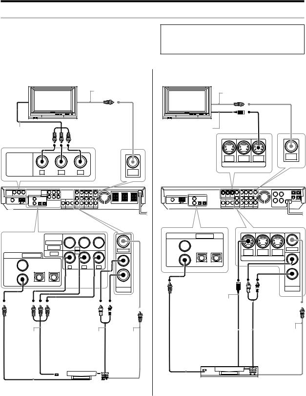
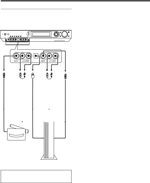
Connecting a DVD player
If you have connected a DVD player to the receiver with digital connection,be
sure to read the "Input mode settings", "Re-assignment of rear panel jacks" section carefully. 8•
÷Digital audio connections are required when playing multi-chan- nel signals such as the Dolby Digital and DTS signals.
÷To play the DVD player connected in this page, select the "DVD" input selector. ª
For U.S.A. and Canada
Monitor TV
COMPOSITE VIDEO IN (Yellow RCA pin cords)
COMPONENT |
|
|
|
|
VIDEO IN |
|
|
|
|
COMPONENT |
|
|
|
|
VIDEO |
|
|
|
|
OUTPUT |
|
|
MONITOR |
|
Y |
CB |
CR |
||
OUT |
To AC wall outlet
COMPONENT
VIDEO INPUT
(ASSIGNABLE)
|
(VIDEO 2) |
IN 2 |
VIDEO IN |
|
(DVD) |
IN 1 |
|
DIGITAL IN (ASSIGNABLE) |
|
||
|
|
||
|
|
|
COAX 2 |
OPT 1 |
OPT 2 |
Y |
CB |
CR |
|
(VIDEO 2) |
(VIDEO 1) |
(AUX) |
||||
|
|
|
||||
COAX 1 |
|
|
|
|
|
|
(DVD) |
|
|
|
|
IN |
|
|
|
|
|
|
||
|
|
|
|
|
DVD |
COMPONENT |
|
AUDIO LINE |
COMPOSITE |
|
VIDEO OUT |
|
OUT or |
VIDEO OUT |
|
|
|
|
MIX LINE OUT |
(Yellow RCA |
|
|
|
(Audio cord) |
pin cords) |
|
|
|
|
|
|
|
|
|
|
|
|
|
|
|
|
|
|
|
|
DIGITAL OUT (AUDIO) |
DVD player |
(Coaxial cord) |
|
For Europe and Australia
Monitor TV |
COMPOSITE |
VIDEO IN
(Yellow RCA pin cords)
S VIDEO IN
(S VIDEO cord)
DVD |
VIDEO 2 |
MONITOR |
MONITOR |
OUT |
|||
IN |
IN |
OUT |
|
S VIDEO
|
|
|
|
To AC wall outlet |
||
DIGITAL IN |
(ASSIGNABLE) |
|
|
|
|
|
COAX 2 |
OPT 1 |
OPT 2 |
|
|
|
VIDEO IN |
(VIDEO 2) |
(VIDEO 1) |
(AUX) |
DVD |
VIDEO 2 |
MONITOR |
|
|
|
|
|
|||
|
|
|
IN |
IN |
OUT |
|
COAX 1 |
|
|
|
S VIDEO |
|
|
(DVD) |
|
|
|
|
|
|
|
|
|
|
|
|
IN |
|
|
|
|
|
|
DVD |
S VIDEO OUT (S VIDEO cord)
|
|
|
|
|
|
|
COMPOSITE |
|
AUDIO LINE OUT or |
||||||||
VIDEO OUT |
||||||||
MIX LINE OUT |
||||||||
(Yellow RCA |
||||||||
(Audio cord) |
||||||||
pin cords) |
||||||||
|
|
|
|
|
|
|
||
|
|
|
|
|
|
|
|
|
|
|
|
|
|
|
|
|
|
|
|
|
|
|
|
|
|
|
DIGITAL OUT (AUDIO) |
DVD player |
(Coaxial cord) |
|
9 EN

Setting up the system
Connecting video components, audio components
For U.S.A. and Canada
Audio components
AUDIO LINE OUT (Audio cord)
Monitor TV
|
|
L |
|
|
|
R |
|
|
MONITOR |
IN |
|
VIDEO IN (Yellow RCA pin cords) |
AUX |
||
OUT |
|||
|
VIDEO IN |
VIDEO OUT |
VIDEO IN |
VIDEO IN |
VIDEO OUT |
VIDEO IN |
PLAY IN |
REC OUT PLAY IN |
|
PLAY IN |
REC OUT PLAY IN |
VIDEO 2 |
VIDEO 1 |
VIDEO 2 |
VIDEO 1 |
|
VIDEO |
AUDIO |
|||||||||||||||||
OUT |
LINE |
|||||||||||||||||
(Yellow |
IN |
|||||||||||||||||
RCA pin |
(Audio |
|||||||||||||||||
cords) |
cord) |
|||||||||||||||||
|
|
|
|
|
|
|
|
|
|
|
|
|
|
|
|
|
|
|
|
|
|
|
|
|
|
|
|
|
|
|
|
|
|
|
|
|
|
|
|
|
|
|
|
|
|
|
|
|
|
|
|
|
|
|
|
|
|
|
|
|
|
|
|
|
|
|
|
|
|
|
|
|
|
|
|
|
|
|
|
|
|
|
|
|
|
|
|
|
|
|
|
|
|
|
|
|
|
|
|
|
|
|
|
|
|
|
|
|
|
|
|
|
|
|
|
Video deck, Cassette |
|
|||
|
|
deck or MD recorder |
AUDIO |
|||
|
|
VIDEO IN |
||||
|
|
LINE OUT |
||||
|
|
(Yellow RCA pin cords) |
||||
|
|
(Audio cord) |
||||
Satellite Cable Tuner |
||||||
|
||||||
|
|
|
|
|
|
|
AUDIO LINE OUT or MIX LINE OUT (Audio cord)
VIDEO OUT (Yellow RCA pin cords)
Connecting video components (COMPONENT VIDEO)
If you have connected the receiver to a video component with COMPONENT jacks, you can get a better picture quality than by connecting to the S VIDEO jacks.
When connecting a video component with COMPONENT jacks, see "Re-assignment of rear panel jacks" •
When connecting the TV to the COMPONENT jacks, be sure to connect all the other components to the COMPONENT jacks.
CB IN 
Y IN 
CR IN 
COMPONENT |
|
|
VIDEO |
|
|
OUTPUT |
|
|
Y |
CB |
CR |
Monitor TV
(with component jacks)
FM 75 Ω
COMPONENT |
|
VIDEO INPUT |
|
(ASSIGNABLE) |
|
(VIDEO 2) |
IN 2 |
(DVD) |
IN 1 |
|
Y |
CB |
CR |
HDD Recorder, DVD Recorder,
Satellite Cable Tuner & Game CR OUT
Player (with component jacks)
CB OUT
 Y OUT CB OUT CR OUT
DVD player (with component jacks)
Y OUT
10 EN
Setting up the system
For Europe and Australia
Audio components
AUDIO LINE OUT (Audio cord)
Monitor TV
|
|
L |
|
|
|
R |
|
|
MONITOR |
IN |
|
VIDEO IN |
AUX |
||
OUT |
(Yellow RCA pin cords)
VIDEO IN |
VIDEO OUT |
VIDEO IN |
VIDEO IN |
VIDEO OUT |
VIDEO IN |
PLAY IN |
REC OUT PLAY IN |
|
PLAY IN |
REC OUT PLAY IN |
VIDEO 2 |
VIDEO 1 |
|
VIDEO 2 |
VIDEO 1 |
VIDEO |
AUDIO |
|||||||||||||||||
OUT |
LINE |
|||||||||||||||||
(Yellow |
IN |
|||||||||||||||||
RCA pin |
(Audio |
|||||||||||||||||
cords) |
cord) |
|||||||||||||||||
|
|
|
|
|
|
|
|
|
|
|
|
|
|
|
|
|
|
|
|
|
|
|
|
|
|
|
|
|
|
|
|
|
|
|
|
|
|
|
|
|
|
|
|
|
|
|
|
|
|
|
|
|
|
|
|
|
|
|
|
|
|
|
|
|
|
|
|
|
|
|
|
|
|
|
|
|
|
|
|
|
|
|
|
|
|
|
|
|
|
|
|
|
|
|
|
|
|
|
|
|
|
|
|
|
|
|
|
|
|
|
|
|
|
Video deck, Cassette |
|
|
deck or MD recorder |
AUDIO |
|
VIDEO IN |
||
LINE OUT |
||
(Yellow RCA pin cords) |
||
|
(Audio cord)
Satellite Cable Tuner
Connecting video components (S VIDEO)
Use the S VIDEO jacks to make connections to video compo-
nents with S VIDEO IN/OUT jacks.
¶If you use the S VIDEO jacks to connect your video playback components, be sure to use the S VIDEO jacks when connecting your monitor and video recording components.
DVD |
VIDEO 2 |
MONITOR |
IN |
IN |
OUT |
|
S VIDEO |
|
S VIDEO IN
(S VIDEO cord)
Monitor TV
(with S VIDEO jack)
S VIDEO OUT (S VIDEO cord)
Satellite Cable Tuner
(with S VIDEO cord)
S VIDEO OUT (S VIDEO cord)
DVD player
(with S VIDEO jack)
AUDIO LINE OUT or MIX LINE OUT (Audio cord)
VIDEO OUT (Yellow RCA pin cords)
11 EN
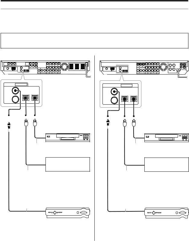
Setting up the system
Digital connections
The digital in jacks can accept DTS,Dolby Digital,or PCM signals.Connect components capable of outputting DTS,Dolby Digital or PCM (CD) digital signals.
If you have connected a DVD player to the receiver with digital connection,be sure to read the "Input mode settings", "Re-assignment of rear panel jacks" section carefully. 8•
DTS disclaimer clause
When playing DTS-encoded discs, excessive noise will be exhibited from the analog stereo outputs of the CD or DVD player. To enjoy DTS Digital Surround™ playback, this unit must be connected to the digital output of the CD or DVD player.
For U.S.A. and Canada
DIGITAL IN |
(ASSIGNABLE) |
|
COAX 2 |
OPT 1 |
OPT 2 |
(VIDEO 2) |
(VIDEO 1) |
(AUX) |
COAX 1 |
|
|
(DVD) |
|
|
CD player or DVD player
OPTICAL DIGITAL OUT (AUDIO) (Optical fiber cord)
OPTICAL DIGITAL OUT (AUDIO) (Optical fiber cord)
COAXIAL DIGITAL OUT (AUDIO) (Coaxial cord)
Component with DTS,
Dolby Digital,or PCM
OPTICAL DIGITAL OUT
Connect the analog audio signals
to the AUX jacks.
(See "Connecting video components,audiocomponents". 0)
Satellite Cable Tuner
Connect the video signal and analog audio signals to the VIDEO 2 jacks.
(See "Connecting video components,audiocomponents". 0)
For Europe and Australia
DIGITAL IN |
(ASSIGNABLE) |
|
COAX 2 |
OPT 1 |
OPT 2 |
(VIDEO 2) |
(VIDEO 1) |
(AUX) |
COAX 1 |
|
|
(DVD) |
|
|
CD player or DVD player
OPTICAL DIGITAL OUT (AUDIO) (Optical fiber cord)
OPTICAL DIGITAL OUT (AUDIO) (Optical fiber cord)
COAXIAL DIGITAL OUT (AUDIO) (Coaxial cord)
Component with DTS,
Dolby Digital,or PCM
OPTICAL DIGITAL OUT
Connect the analog audio signals
to the AUX jacks.
(See "Connecting video components,audiocomponents". !)
Satellite Cable Tuner
Connect the video signal and analog audio signals to the VIDEO 2 jacks.
(See "Connecting video components,audiocomponents". !)
12 EN
Setting up the system
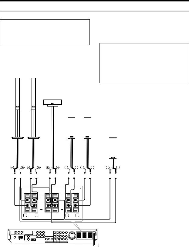
Connecting the speakers
For U.S.A. and Canada
CAUTION
Make sure that the power cord plug is disconnected from the AC wall outlet before proceeding to speaker cord connections.
If the conductor wires on the extremity of speaker cord are untwisted, there is a risk of short-circuiting. Be sure to twist them well before connecting the speaker cord.
Whether each speaker is connected properly can be confirmed by outputting the test tone and checking if each speaker channel outputs audio. For details, see "Speaker settings" (Step 6 Adjust the speaker volume level). §
|
Protection circuitry |
|
This unit incorporates protection circuitry, which may be activated |
|
during high-power reproduction or in case of extreme rise in tempera- |
|
ture. |
|
When the protection circuitry is activated, the output from this unit is |
|
shut down and the STANDBY indicator blinks. |
Front Speakers |
In this case, turn this unit OFF then ON again and reduce the output |
|
volume level. |
Right |
Left |
|
Center |
|
Speaker |
|
Surround Speakers |
|
Be sure to connect both surround speakers |
|
|
|
|
|
|
|
|
|
|
|
|
|
|
|
|
|
|
|
|
|
|
|
|
Subwoofer/ Surround Back Speaker |
|
|
|
|
|
|
|
|
|
|
|
|
|
|
|
|
|
|
|
|
|
|
|
|
|
|
|
|
|
|
|
|
|
|
|
|
|
|
|
|
|
|
|
|
|
|
|
|
|
When the surround back speaker is connected to these |
|
|
|
|
|
|
|
|
|
|
|
|
|
|
|
|
|
|
|
|
|
|
|
|
terminals, set the speaker setting to "BS/SW BS". |
|
|
|
|
|
|
|
|
|
|
|
|
|
|
|
|
|
|
|
|
|
|
|
|
In this case, the subwoofer should be connected to the |
Right |
|
|
|
|
|
|
Left |
|
|
|
PRE OUT SUBWOOFER jack ^ |
|||||||||||||
|
|
|
|
|
|
|
|
|||||||||||||||||
|
|
|
|
|
|
|
|
|||||||||||||||||
|
|
|
|
|
|
|
|
|
|
|
|
|
|
|
|
|
|
|
|
|
|
|
|
|
SPEAKERS (6-8Ω)
R FRONT L |
CENTER SURR BACK /SW
R SURR L |
13 EN
Setting up the system
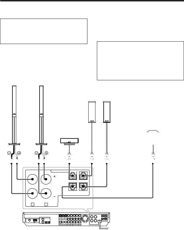
For Europe and Australia
CAUTION
Make sure that the power cord plug is disconnected from the AC wall outlet before proceeding to speaker cord connections.
If the conductor wires on the extremity of speaker cord are untwisted, there is a risk of short-circuiting. Be sure to twist them well before connecting the speaker cord.
Whether each speaker is connected properly can be confirmed by outputting the test tone and checking if each speaker channel outputs audio. For details, see "Speaker settings" (Step 6 Adjust the speaker volume level). §
Protection circuitry
This unit incorporates protection circuitry, which may be activated during high-power reproduction or in case of extreme rise in temperature.
When the protection circuitry is activated, the output from this unit is shut down and the STANDBY indicator blinks.
In this case, turn this unit OFF then ON again and reduce the output volume level.
Front Speakers
Right |
Left |
Center
Speaker
Surround Speakers
Be sure to connect both surround speakers
|
|
|
|
|
|
|
|
|
|
|
|
|
|
Subwoofer/ Surround Back Speaker |
||||||
|
|
|
|
|
|
|
|
|
|
|
|
|
|
When the surround back speaker is connected to these |
||||||
|
|
|
|
|
|
|
|
|
|
|
|
|
|
terminals, set the speaker setting to "BS/SW BS". |
||||||
|
|
|
|
|
|
|
|
|
|
|
|
|
|
In this case, the subwoofer should be connected to the |
||||||
|
|
|
|
|
|
|
|
|
|
|
|
|
|
|||||||
Right |
|
|
|
Left |
PRE OUT SUBWOOFER jack ^ |
|||||||||||||||
|
|
|
|
|
|
|
|
|
|
|||||||||||
|
|
|
|
|
|
|
|
|
|
|
|
|
|
|
|
|
|
|
|
|
|
|
|
|
|
|
|
|
|
|
|
|
|
|
|
|
|
|
|
|
|
|
|
|
|
|
|
|
|
|
|
|
|
|
|
|
|
|
|
|
|
|
|
|
|
|
|
|
|
|
|
|
|
|
|
|
|
|
|
|
|
|
|
|
|
|
|
|
|
|
|
|
|
|
|
|
|
|
|
|
|
|
|
|
|
|
|
|
|
|
|
|
|
|
|
|
|
|
|
|
|
|
|
|
|
SPEAKERS (6-8Ω) 

CENTER SURR R
SURR BACK SURR L /SW
R FRONT L
14 EN
Setting up the system
Connecting the speaker terminals
For U.S.A. and Canada
1 |
Strip coating. |
3 |
Insert the cord. |
|
Twist |
|
|
2 |
Push the lever. |
4 |
Return the lever. |
For Europe and Australia
1 Strip coating. |
3 Insert. |
Twist |
|
2 Loosen. |
4 Secure. |
If the provided speaker cords are too short, they can be replaced with commercially available speaker cords [AWG24-18 standard (conductor section diameter 0.511 to 1.024 mm(0.02 to 0.04 in.))]. When using commercially available speaker cords, strip the vinyl coating on the end of each cord by about 1 cm (0.39 in.) and twist the conductor wires so that they are not disentangled.
Attaching the speaker cord connectors;
Connect each speaker cord by matching the color of the connector with that of the terminal to which the speaker cord is to be connected.
Connected speaker |
Connector |
Connected |
|
terminal |
|||
|
|
||
Center speaker |
Green |
CENTER |
|
|
|
|
|
Surround speaker (Right) |
Grey |
SURR R |
|
|
|
|
|
Surround speaker (Left) |
Blue |
SURR L |
|
|
|
|
|
Surround back speaker |
Brown |
SURR BACK/SW |
|
or Subwoofer |
|||
|
|
||
|
|
|
While applying the projected part of the connector against a hard desktop, etc., insert the conductor sections of the speaker cord into the connector.
Projected part (White)
¶After attaching the speaker cord connector, hold it and pull the speaker cord lightly to ensure that it will not come out.
Connect the connector to the terminal on the receiver with the same color by inserting the connector straight until it clicks.
Green |
Grey |
|
CENTER |
SURR R |
|
Brown |
|
Confirm the connector |
|
|
|
SURR BACK |
SURR L |
orientation before insertion. |
/SW |
|
|
|
Blue |
|
¶Never short circuit the + and – speaker cords.
¶If the left and right speakers are connected inversely or the speaker cords are connected with reversed polarity, the sound will be unnatural with ambiguous acoustic imaging. Be sure to connect the speakers correctly.
Speaker impedance
After confirming the speaker impedance indications printed on the rear panel of the receiver, connect speakers with matching impedance ratings. Using speakers with a rated impedance other than that indicated on the rear panel of the receiver could result in malfunctions or damage to the speakers or receiver.
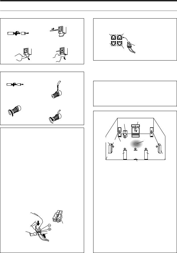
Speaker placement
Center speaker
Subwoofer |
|
|
Surround |
Listening |
|
speakers |
||
position |
||
Front |
||
|
||
speakers |
|
|
*Surround Back |
*Surround Back |
|
*Left speaker |
*Right speaker |
*Surround Back speaker
*For Surround Back speaker, you may place either two Surround Back speakers (Surround Back Left speaker and Surround Back Right speaker) for 7.1 channel surround sound system or one Surround Back speaker for 6.1 channel surround sound system.
Front speakers : Place the left and right speakers at each side of your TV. Angle the speakers towards the listening area to enhance the stereo effect.
Center speaker : Place the center speaker on the center between the front left and right speakers. Tilt the speaker upward or down-ward so that it is directly facing the listening area.
Surround speakers : Place the surround speakers as high as possible, either directly to the sides of the listening area or else slightly behind the listening area. Adjust the angles so that these speakers are facing directly towards the listeners.
Subwoofer : Usually, place the subwoofer in the front center position in the listening room, near one of the front speakers near the center speaker. (Since the subwoofer has less directivity than other speakers, it can be placed almost in any position that can offer the best low frequency reproduction according to the room layout.)
Surround back speakers : Place the surround back speaker behind the listining position, at the same height as the left and right surround speakers.
¶Although the ideal surround system consists of all the speakers listed above, if you don't have a center speaker or a subwoofer, you can divide those signals between the available speakers in the speaker settings steps to obtain the best possible surround reproduction from the speakers you have available. ¢
15 EN
Setting up the system
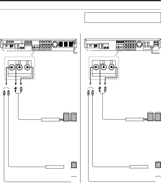
PRE OUT connections
The receiver has additional PRE OUT jacks.
Note that the output from the PRE OUT jacks needs to be connected to an external power amplifier.
If you want to connect surround back speakers to these jacks, be always sure to connect two surround back speakers for the left and right.
¶Connecting a speaker cord directly to a PRE OUT jack will not produce any sound from the speaker.
For U.S.A. and Canada
R |
L |
SUB |
|
WOOFER SURROUND BACK |
|
PRE OUT
Example:
¶ When you want to connect two surround back speakers.
¶When the subwoofer is connected to the
SURR BACK/SW terminals.
Surround Back speakers
L R
Power amplifier
Example:
¶When the surround back speaker is connected to the SURR BACK/SW terminals.
Subwoofer
Power amplifier
For Europe and Australia
R |
L |
SUB |
|
WOOFER SURROUND BACK |
|
PRE OUT
Example:
¶ When you want to connect two surround back speakers.
¶When the subwoofer is connected to the
SURR BACK/SW terminals.
Surround Back speakers
L R
Power amplifier
Example:
¶When the surround back speaker is connected to the SURR BACK/SW terminals.
Subwoofer
Power amplifier
Powered subwoofer |
Powered subwoofer |
||
|
|
|
|
|
|
|
|
16 EN
Setting up the system
Connecting to the GAME jacks / FRONT AUX jacks
If you use a component that you do not usually connect to the receiver, such as a portable video camera, connect it to the GAME or FRONT AUX jacks on the front panel of the receiver. These jacks are particularly convenient when dubbing audio/video from a portable video camera.
INPUT SELECTOR
|
|
|
|
OPTICAL |
|
|
|
|
||
|
|
|
|
DIGITAL |
|
|
|
|
||
VIDEO |
|
OUT |
AUDIO |
|||||||
OUT |
|
(AUDIO) |
OUT |
|||||||
|
AUDIO |
|
|
|
|
|
|
VIDEO |
||
|
|
|
|
|
|
|
||||
|
OUT |
|
|
|
|
|
|
OUT |
||
|
|
|
|
|
|
|
|
|
|
|
|
|
|
|
|
|
|
|
|
|
|
|
|
|
|
|
|
|
|
|
|
|
Camcorder
Game Player
¶The DIGITAL IN (OPTICAL) jack in the GAME jack section can be used for connection of digital audio input. This is convenient for playing a video game through the receiver. ¶
17 EN
Setting up the system
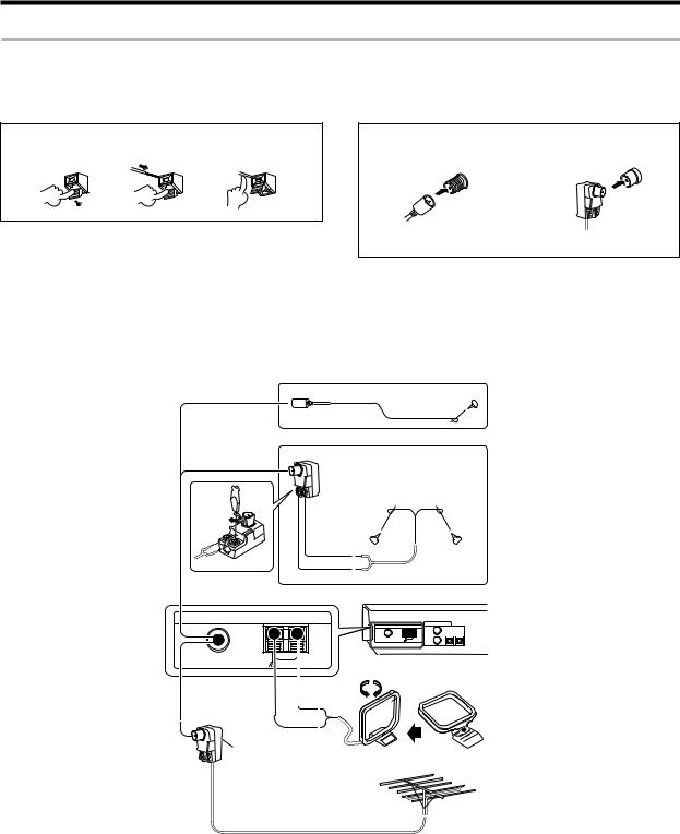
Connecting the antennas
AM loop antenna
The supplied loop antenna is for use indoors. Place it as far as possible from the receiver, TV set, speaker cords and power cord, and adjust the direction for best reception.
FM indoor antenna
The supplied indoor antenna is for temporary use only. For stable signal reception we recommend using an outdoor antenna. Disconnect the indoor antenna when you connect one outdoors.
AM antenna terminal connections
1 Push lever. |
2 Insert cord. |
3 Release lever. |
FM antenna terminal connections
Insert the connector.
(For the U.S.A. and Canada) |
(For Europe and Australia) |
FM outdoor antenna
Lead the 75Ωcoaxial cable connected to the FM outdoor antenna into the room and connect it to the FM 75Ω terminal.
For the U.S.A. and Canada
FM indoor antenna
For Europe and Australia
Antenna adaptor
FM indoor antenna
|
ANTENNA |
|
FM 75 Ω |
GND |
AM |
|
|
White |
Black
Use an antenna adaptor (Commercially available)
Attach to the stand
AM loop antenna
FM outdoor antenna
18 EN
Setting up the system
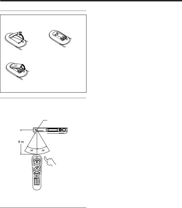
Preparing the remote control
Loading the batteries
1 Remove the cover. |
2 Insert the batteries. |
3 Close the cover.
¶Insert two AA-size (R6) batteries as indicated by the polarity markings.
Remote control operation
When the STANDBY indicator is lit, the power turns ON when you press the POWER RCVR on the remote control. When the power comes ON, press the key you want to operate.
Operating other |
|
|
Remote sensor |
||
component range |
|
|
|
|
|
|
|
|
|
|
|
|
|
|
|
|
|
|
|
|
|
|
|
|
|
|
|
|
|
|
|
|
|
|
|
POWER RCVR 
¶When pressing more than one remote control key successively, press the keys securely by leaving an interval of 1 second or more between keys.
Notes
1.The supplied batteries may have shorter lives than ordinary batteries due to use during operation checks.
2.When the remote-controllable distance gets shorter than before, replace both batteries with new ones.
3.Placing the remote sensor in direct sunlight, or in direct light from a high frequency fluorescent lamp may cause a malfunction.
In such a case, change the location of the system installation to prevent malfunction.
19 EN
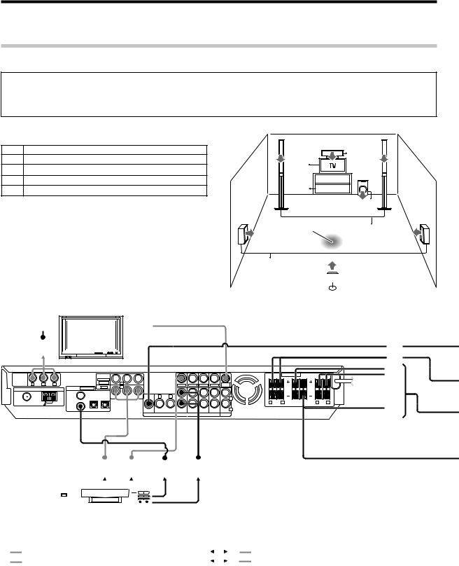
Let’s play DVD video software (For U.S.A. and Canada)
STEP 1 Connect the speakers and TV to the receiver.
For details, see "Setting up the system" 8~ &
CAUTION
Make sure that the power cord plug is disconnected from the AC wall outlet before proceeding to speaker cord connections.
If the conductor wires on the extremity of speaker cord are untwisted, there is a risk of short-circuiting. Be sure to twist them well before connecting the speaker cord.
Connection of speakers: |
|
|
C |
|
|
||
A |
Front speakers (L,R) |
|
|
B |
|
||
|
|
|
|
||||
|
|
|
|
|
|||
B |
Center speaker |
|
1~ |
|
|
|
|
C |
Subwoofer |
L |
|
SW |
R |
||
D |
Surround speakers (L,R) |
1~ |
RECEIVER |
||||
|
|
|
|||||
E |
Surround back speaker |
|
DVD |
|
|
||
÷ If you want to connect two surround back speakers (LB and RB) |
|
|
C |
|
to the PRE OUT SURROUND BACK jacks, see "PRE OUT |
LS |
|
RS |
|
connections". ^ |
Listening position |
|||
|
A |
|||
|
|
|
D
BS 
 E
E


 2
2 1
1 
COMPONENT |
|
|
|
COMPONENT |
|
|
|
|
|
|
|
SPEAKERS (6-8Ω) |
|
|
|
||
|
|
|
VIDEO INPUT |
|
|
|
|
|
|
|
|
|
|
|
|
||
VIDEO |
|
|
|
(ASSIGNABLE) |
|
|
|
|
|
|
|
|
|
|
|
|
|
OUTPUT |
|
|
|
|
(VIDEO 2) |
|
|
|
|
|
|
|
|
|
|
|
|
|
Y |
|
CR |
|
|
|
|
|
|
|
MONITOR |
|
|
|
|
|
|
|
|
|
DIGITAL IN |
(ASSIGNABLE) |
(DVD) |
|
|
|
VIDEO IN |
VIDEO IN |
VIDEO OUT VIDEO IN |
OUT |
|
|
|
|
|
|
ANTENNA |
|
|
|
|
|
|
|
|
|
|
|
|
|
|
||
|
|
|
COAX 2 |
OPT 1 |
OPT 2 |
Y |
R |
L |
|
|
|
|
|
|
|
|
|
|
|
|
(VIDEO 2) |
(VIDEO 1) |
(AUX) |
|
|
|
|
|
|
L |
|
|
|
|
|
FM 75 Ω |
|
|
|
|
|
|
|
|
|
|
|
R FRONT |
L |
CENTER |
SURR BACK |
R SURR |
L |
GND |
AM |
COAX 1 |
|
|
|
|
|
|
|
|
|
|
|
/SW |
|
|
|
|
|
|
(DVD) |
|
|
SUB |
|
|
|
|
|
R |
|
|
|
|
|
|
|
|
|
|
|
WOOFER |
SURROUND BACK |
IN |
PLAY IN |
REC OUT PLAY IN |
IN |
|
|
|
|
|
|
|
|
|
|
|
|
|
PRE OUT |
|
DVD |
VIDEO 2 |
VIDEO 1 |
AUX |
|
|
|
|
|
C A
B D E
1 2 3 4
|
|
|
|
|
|
|
|
|
|
|
|
Connection of DVD player: |
||
|
|
|
|
|
|
|
|
|
|
|
|
|||
|
|
|
|
|
|
|
|
|
|
|
|
|||
Connection of TV monitor: |
|
|||||||||||||
|
|
|
|
|
|
|
|
|
|
|
|
|
|
|
1 |
Component video connection |
|
|
|
1 |
Component video connection |
||||||||
|
|
|
||||||||||||
2 |
Composite video connection |
|
|
|
2 |
Composite video connectiona |
||||||||
|
|
|
||||||||||||
|
|
|
|
|
|
|
|
|
|
|
|
|
|
|
÷ For the video input connection from the DVD player and the video |
|
|
|
|
||||||||||
|
|
3 |
Digital audio connection (Coaxial cord) |
|||||||||||
output connection to the TV monitor, use either the component video |
|
|
||||||||||||
|
|
4 |
Analog audio connection |
|||||||||||
or composite video connection for both of them. |
|
|
||||||||||||
20 EN
 Loading...