


AMPLIFIER-TUNER/CD PLAYER
RD-VH7
CASSETTE TAPE DECK
X-VH7
INSTRUCTION MANUAL
KENWOOD CORPORATION
Before installation, be sure to read “System configuration” and “Installa-
tion” in this manual to ensure correct installation. |
0,! |
This instruction manual is used to describe multiple models listed above. Model availability and features (functions) may differ depending on the country and sales area.
COMPACT
DIGITAL AUDIO
TEXT
B60-4280-10 EN
2 |
Before applying power |
Caution : Read this page carefully to |
ensure safe operation. |
|
Before applying power |
||
|
|
|
|
|
|
|
RD-VH7/X-VH7 (EN) |
Units are designed for operation as follows.
U.S.A. ............................................................................. |
AC 120 V only |
EUROPE & U.K. ............................................................ |
AC 230 V only |
SAFETY
Safety precautions
WARNING : TO PREVENT FIRE OR ELECTRIC SHOCK, DO NOT EXPOSE THIS APPLIANCE TO RAIN OR MOISTURE.
CAUTION
RISK OF ELECTRIC SHOCK
DO NOT OPEN
CAUTION: TO REDUCE THE RISK OF ELECTRIC SHOCK, DO NOT REMOVE COVER (OR BACK). NO USER-SERVICEABLE PARTS INSIDE. REFER SERVICING TO QUALIFIED SERVICE PERSONNEL.
THE LIGHTNING FLASH WITH ARROWHEAD SYMBOL, WITHIN AN EQUILATERAL TRIANGLE, IS INTENDED TO ALERT THE USER TO THE PRESENCE OF UNINSULATED “DANGEROUS VOLTAGE” WITHIN THE PRODUCT’S ENCLOSURE THAT MAY BE OF SUFFICIENT MAGNITUDE TO CONSTITUTE A RISK OF ELECTRIC SHOCK TO PERSONS.
THE EXCLAMATION POINT WITHIN AN EQUILATERAL TRIANGLE IS INTENDED TO ALERT THE USER TO THE PRESENCE OF IMPORTANT OPERATING AND MAINTENANCE (SERVICING) INSTRUCTIONS IN THE LITERATURE ACCOMPANYING THE APPLIANCE.
The marking of products using lasers (Except for some areas)
|
|
|
|
|
|
|
|
|
|
|
|
CAUTION |
|
|
|
|
|
|
||
|
CLASS 1 |
|
|
|
INVISIBLE LASER RADIATION |
|
|
LASER PRODUCT |
|
|
|
WHEN OPEN. AVOID EXPOSURE |
|
|
|
|
|
|
TO BEAM. |
|
|
|
|
|
|
||
|
|
|
|
|
|
|
The marking is located on the rear panel and says that this product has been classified as Class 1. It means that there is no danger of hazardous radiation outside the product.
Inside of this laser product, a component (a laser diode: Wavelength: 760-800nm) classified as Class 3A laser radiation is contained as alerted by the internal caution label shown above. To avoid exposure to laser beams, do not open the cover.
3
Before applying power
RD-VH7/X-VH7 (EN)
Contents
Caution : Read the pages marked  carefully to ensure safe operation.
Before applying power ....................................... |
2 |
Introduction ........................................................... |
6 |
Special features ................................................................ |
7 |
SAFETY |
|
IMPORTANT SAFEGUARDS................................ |
8 |
PREPARATION |
|
TUNER OPERATIONS |
|
Receiving broadcast station…........................ 34 |
|
Selecting a preset station (Preset call) .................... |
34 |
Manual tuning and preset operation ........................ |
35 |
Using R.D.S. (Radio Data System) |
|
(For U.K. and Europe ) ..................................... |
36 |
Searching for a desired program type |
|
System configuration, Installation.................. |
10 |
System configuration .................................................... |
10 |
Installation ...................................................................... |
11 |
System connection ............................................ |
12 |
Connection of antenna .................................................. |
12 |
Connection of audio cord ............................................. |
13 |
Connection of system control cord ............................ |
14 |
Connection of speakers ................................................ |
15 |
Controls and indicators..................................... |
16 |
Main Unit ......................................................................... |
16 |
Remote control Unit ....................................................... |
18 |
Operation of remote control unit ..................... |
20 |
Clock adjustment ............................................... |
21 |
BASIC OPERATIONS |
|
Hearing sound..................................................... |
22 |
CD OPERATIONS |
|
Playback of CD ................................................... |
26 |
Recording a HDCD disc ................................................ |
29 |
Listening in the desired sequence |
|
(program playback) ........................................... |
30 |
Repeated playback .............................................. |
32 |
Playing tracks in a random order |
|
(random playback) ............................................. |
33 |
(PTY search) ................................................................ |
|
37 |
To be able to listen to the desired information at any |
||
time (EON reservation) .............................................. |
38 |
|
CASSETTE DECK OPERATIONS |
|
|
Playback of tape ................................................. |
|
40 |
DPSS (Direct Program Search System) ..................... |
42 |
|
Recording onto cassette tape .......................... |
44 |
|
Recording CD tracks in the desired sequence |
|
|
(Program recording) |
.......................................... |
47 |
Recording only desired tracks |
|
|
(ONE TOUCH EDIT..... |
single track recording) ...... |
48 |
One-touch recording of an entire CD |
|
|
(ONE TOUCH EDIT..... |
recording of all tracks) ........ |
49 |
TIMER OPERATIONS |
|
|
Timer operation .................................................. |
|
50 |
O.T.T. Timer ..................................................................... |
|
50 |
Program timer playback (AI timer playback) |
|
|
and timer recording .................................................... |
|
51 |
Sleep timer ...................................................................... |
|
54 |
REFERENCE INFORMATION |
|
|
Important Items ................................................... |
|
55 |
Handling of discs and tapes ........................................ |
55 |
|
Precautions and Notes ................................................. |
57 |
|
In case of difficulty ............................................ |
|
58 |
Specifications..................................................... |
|
62 |
4
Before applying power
RD-VH7/X-VH7 (EN)
Demonstration
The demonstration consists of sequential switching of display for showing the functions available with the system.
The audio does not change while the demonstration is active.
Demonstration cannot be started during playback (or recording) of a source.
÷Provided that the power is set to ON, demonstration is switched automatically to “DEMO ON” after there is a power failure or the power cord is unplugged then plugged in again.
DEMO ON (Demonstration executed):
While the power is set to ON , press and hold the “auto/mono, demo” key on the amplifier-tuner/ CD player for more than 2 seconds.
auto /mono
demo
DEMO OFF (Demonstration cancelled):
÷Press the “auto/mono, demo” key in the “DEMO ON” mode.
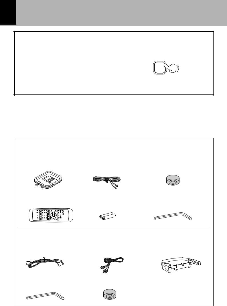
Accessories
Accessories supplied with RD-VH7
AM loop antenna (1) |
FM indoor antenna (1) |
Replacement front feet (2) |
Remote control unit (1) |
Batteries (R6/AA) (2) |
Front feet replacement tool |
|
|
(Allen wrench) (1) |
O.T.E. |
|
|
Accessories supplied with X-VH7 (optional)
System control cord (1) |
Audio cord (2) |
Spacer for stacked installation (1) |
||
|
|
|
|
|
|
|
|
|
|
Front feet replacement tool |
Replacement front feet (2) |
(Allen wrench) (1) |
|

5
Before applying power
RD-VH7/X-VH7 (EN)
Note on the instruction manuals
Among the VH series models, some are provided with a system instruction manual describing both the RD-VH7 (amplifier-tuner/ CD player) and X-VH7 (cassette deck) while some are provided with an independent instruction manual describing only the purchased model. This is intended to facilitate each purchaser perform system operations any time if he or she purchases other separately available system components later. Please read the information related only to the model you purchased if the manual provided with it contains information on other models.
For the DM-VH7 (MD recorder) in the VH series, only the connection method is described in the system instruction manual. For details on the DM-VH7, please refer to the independent instruction manual provided with it.
Model (Purchased model) |
Provided Manual (Models described in it) |
|
|
Amplifier-tuner/CD player (RD-VH7) |
System instruction manual (RD-VH7, X-VH7) |
|
|
Cassette deck (X-VH7) |
Independent instruction manual (X-VH7) |
|
|
MD recorder (DM-VH7) |
Independent instruction manual (DM-VH7) |
|
|
Unpacking
Unpack the unit carefully and make sure that all accessories are put aside so they will not be lost.
Examine the unit for any possibility of shipping damage. If your unit is damaged or fails to operate, notify your dealer immediately. If your unit was shipped to you directly, notify the shipping company without delay. Only the consignee (the person or company receiving the unit) can file a claim against the carrier for shipping damage.
We recommend that you retain the original carton and packing materials for use should you transport or ship the unit in the future.
Keep this manual handy for future reference.

6 Introduction
Before applying power
RD-VH7/X-VH7 (EN)
VH series
Thank you for purchasing an VH series product.
The VH series system components include the amplifier-tuner/ CD player, MD recorder and cassette deck, so the user can select and purchase desired models among them.
By connecting some of these components using KENWOOD system control cords, convenient system operations will be available as described below.
Remote control
The basic operations of the source components (cassette deck, MD recorder) can be controlled from the remote control unit provided with the amplifier-tuner/ CD player.
Automatic operation
When an input source is selected on the amplifier-tuner/ CD player, the source component of the newly selected source (CD player, MD recorder, cassette deck, tuner) starts playback automatically.
Synchronized recording
When recording audio of a CD or MD onto a cassette, the recording of the cassette deck can be started automatically in synchronism with the start of playback of the source component.
Timer operations
The recording or playback of a source component (CD player, cassette deck, MD recorder, tuner) can be started automatically using the timer built into the amplifier-tuner/ CD player.
VH series components
RD-VH7 (Amplifier-tuner/ CD player)
DM-VH7 (MD recorder)
X-VH7 (Cassette deck)
Note on installation
Be sure to read “System configuration” (page 10) and “Installation” (page 11) before installing the system.
7
Before applyingIntroductionpower
RD-VH7/X-VH7 (EN)
Special features
Amplifier designed with emphasis on sound quality (Pure A amplification)
The Pure A class reproduction mode is built in to improve the sound quality during low-level listening. The sound quality is switched automatically into AB-class as the volume level is decreased to ensure transparent, clear sound at all levels.
Free layout
The system components can be installed vertically on the sides (lengthwise) as well as the conventional, horizontally stacked installation. Much flexible system setting than before is now possible.
LCD (Liquid Crystal Display) with backlit illumination
A high-definition graphic display on each component shows the operating modes such as CD playback and tuner reception conditions at a glance. The display orientation can be changed according to whether the system components are installed vertically or stacked horizontally.
CD player with HDCD (High-Definition Compatible Digital recording) compatibility
CDs recorded in the HDCD format can be played back with higher resolution and wider dynamic range. CDs recorded in the normal format can naturally be played back more delicately than before.
“ ,HDCD®, High Definition Compatible Digital® and Pacific Microsonics™ are either registered trademarks or trademarks of Pacific Microsonics, Inc. in the United States and/or other countries.”
CD-TEXT data display
The text data (disc title, track titles) recorded in CDs can be displayed on the LCD.
R.D.S. (Radio Data System) (For U.K. and Europe)
The RDS data included in FM broadcasts can be used to search for the intended broadcasting contents and for automatic reception from standby.
One-touch operation playback
Even when the power is set to OFF (standby), simply pressing the play key on the front panel of the CD player, MD recorder or tape deck or the “band” key of the tuner starts playback of the corresponding source component immediately.
Convenient timer functions
1O.T.T. timer :
When the set time comes, a source starts to play automatically only for an hour.
2Program timer for playback (AI timer playback) and timer recording:
Two timer programs (PROG.1 and PROG.2) are available for each of the timer playback (AI timer playback) and timer recording functions. (When playback is started with the AI timer, the volume increases automatically until the specified level.)
3Sleep timer :
When the set time comes, the power of the system is set automatically to OFF (standby). This is convenient for example when you want to fall asleep while listening to music.
8 IMPORTANT SAFEGUARDS
Please read all of the safety and operating instructions before operating this appliance. Adhere to all warnings on the appliance and in the instruction manual. Follow all the safety and operating instructions. These safety and operating instructions should be retained for future reference.
|
1. Power sources – The appliance should be connected |
|
SAFETY |
to a power supply only of the type described in the in- |
|
struction manual or as marked on the appliance. If you |
||
|
||
|
are not sure of the type of power supply to your home, |
|
|
consult your appliance dealer or local power company. |
|
|
For appliances intended to operate from battery power, |
|
|
or other sources, refer to the instruction manual. |
|
|
2. Power-cord protection – Power-supply cords should |
|
|
be routed so that they are not likely to be walked on or |
|
|
pinched by items placed upon or against them, pay par- |
|
|
ticular attention to cords at plugs, convenience recepta- |
|
|
cles, and the point where they exit from the appliance. |
|
|
Never pull or stretch the |
|
|
cord. |
3. CAUTION – Polarization – This appliance may be equipped with a polarized alternating-current line plug (a plug having one blade wider than the other). This plug will fit into the power outlet only one way. This is a safety feature. If you are unable to insert the plug fully into the outlet, try reversing the plug. If the plug should still fail to fit, contact your electrician to replace your obsolete outlet. Do not defeat the safety purpose of the polarized plug.
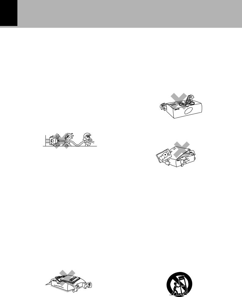
4.Ventilation – Slots and openings in the cabinet are provided for ventilation and to ensure reliable operation of the appliance and to protect it from overheating, and these openings must not be blocked or covered. The appliance should be situated so that its location or position does not interfere with its proper ventilation.
To maintain good ventilation, do not put records or a tablecloth on the appliance. Place the appliance at least 10 cm away from the walls.
Do not use the appliance on a bed, sofa, rug or similar surface that may block the ventilation openings. This appliance should not be placed in a built-in installation such as a bookcase or rack unless proper ventilation is provided or the manufacturer’s instructions have been adhered to.
5.Water and moisture – The appliance should not be used near water - for example, near a bathtub, washbowl, kitchen sink, laundry tub, in a wet basement, or near a swimming pool, etc.
6.Temperature – The appliance may not function properly if used at extremely low, or freezing temperatures. The ideal ambient temperature is above +5°C (41°F).
 Caution : Read this page carefully to ensureBeforesafeapplyingoperationpower.
RD-VH7/X-VH7 (EN)
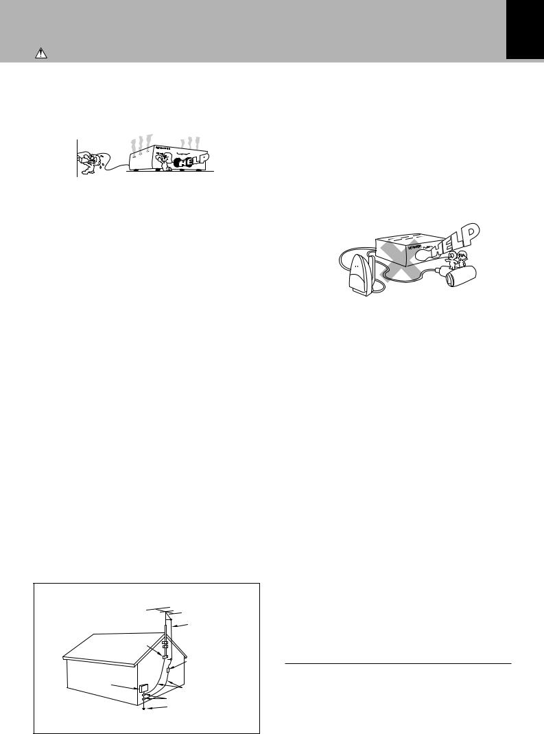
7.Heat – The appliance should be situated away from heat sources such as radiators, heat registers, stoves, or other appliances (including amplifiers) that produce heat.
8.Electric shock – Care should be taken so that objects do not fall and liquid is not spilled into the enclosure through openings. If a metal objects, such as a hair pin or a needle, comes into contact with the inside of this appliance, a dangerous electric shock may result. For families with children, never permit children to put anything, especially metal, inside this appliance.
9.Enclosure removal – Never remove the enclosure. If the internal parts are touched accidentally, a serious electric shock might occur.
10.Magnetic fields – Keep the appliance away from sources of magnetic fields such as TV sets, speaker systems, radios, motorized toys or magnetized objects.
11.Cleaning – Unplug this appliance from the wall outlet before cleaning. Do not use volatile solvents such as alcohol, paint thinner, gasoline, or benzine, etc. to clean the cabinet. Use a clean dry cloth.
12.Accessories – Do not place this appliance on an unstable cart, stand, tripod, bracket, or table. The appliance may fall, causing serious injury to a child or adult, and serious damage to the appliance. Use only with a cart, stand, tripod, bracket, or table recommended by the manufacturer, or sold with the appliance. Any mounting of the appliance should follow the manufacturer’s instructions, and should use a mounting accessory recommended by the manufacturer. An appliance and cart combination should be moved with care. Quick stops, excessive force, and uneven surfaces may cause the appliance and cart combination to overturn.
13.Lightning – For added protection for this appliance during a lightning storm, or when it is left unattended and unused for long periods of time, unplug it from the wall outlet and disconnect the antenna or cable system. This will prevent damage to the appliance due to lightning and power-line surges.
9
Caution : Read this page carefully to ensure safe operation. |
IMPORTANTBeforeapplyingSAFEGUARDSpower |
|
RD-VH7/X-VH7 (EN) |
14.Abnormal smell – If an abnormal smell or smoke is detected, immediately turn the power OFF and unplug the appliance from the wall outlet. Contact your dealer or nearest service center.
15.Damage requiring service – The appliance should be serviced by qualified service personnel when:
A.The power-supply cord or the plug has been damaged.
B.Objects have fallen, or liquid has been spilled into the appliance.
C.The appliance has been exposed to rain or water.
D.The appliance does not appear to operate normally by following the instruction manual. Adjust only those controls that are covered by the instruction manual as an improper adjustment of other controls may result in damage and will often require extensive work by a qualified technician to restore the appliance to its normal operation.
E.The appliance has been dropped, or the enclosure damaged.
F.The appliance exhibits a marked change in performance.
16.Servicing – The user should not attempt to service the appliance beyond that described in the instruction manual. All other servicing should be referred to qualified service personnel.
17.Outdoor antenna grounding – If an outside antenna is connected to the appliance, be sure the antenna system is grounded so as to provide some protection against voltage surges and built up static charges. Article 810 of the National Electrical Code ANSI/ NFPA 70, provides information with respect to proper grounding of the mast and supporting structure, grounding of the lead-in wire to an antenna discharge unit, size of grounding conductors, location of antenna discharge unit, connection to grounding electrodes, and requirements for the grounding electrode. See Figure.
18.Power lines – An outside antenna system should not be located in the vicinity of overhead power lines or other electric light or power circuits, or where it can fall into such power lines or circuits. When installing an outside antenna system, extreme care should be taken to keep from touching such power lines or circuits as contact with them might be fatal.
19.AC outlets – Do not connect other audio equipment with a power consumption larger than that specified to the AC outlet on the rear panel. Never connect other electrical appliances, such as an iron or toaster, to it to prevent fire or electric shock.
20.Overloading – Do not overload wall outlets, extension cords, or integral convenience receptacles as this can result in a risk of fire or electric shock.
21.Attachment – Do not use attachments not recommended by the appliance manufacturer as they may cause hazards.
22.Replacement parts – When replacement parts are required, be sure the service technician has used replacement parts specified by the manufacturer or have the same characteristics as the original parts. Unauthorized substitutions may result in fire, electric shock, or other hazards.
23.Safety check – Upon completion of any service or repairs to this appliance, ask the service technician to perform safety checks to determine that the appliance is in proper operating condition.
SAFETY
EXAMPLE OF ANTENNA GROUNDING AS
PER NATIONAL ELECTRICAL CODE
|
ANTENNA |
|
LEAD IN WIRE |
GROUND |
|
CLAMPS |
ANTENNA |
|
DISCHARGE UNIT |
|
(NEC SECTION 810-20) |
ELECTRIC |
GROUNDING |
SERVICE |
|
EQUIPMENT |
CONDUCTORS |
|
(NEC SECTION 810-21) |
|
GROUND CLAMP |
|
POWER SERVICE |
|
GROUNDING |
|
ELECTRODE SYSTEM |
|
(NEC ART 250, PART H) |
NEC – NATIONAL ELECTRICAL CODE
Notes:
1.Item 3 is not required except for grounded or polarized equipment.
2.Item 17 and 18 are not required except for units provided with antenna terminals.
3.Item 17 complies with UL in the U.S.A.
10 System configuration, Installation
System configuration, Installation
RD-VH7/X-VH7 (EN)
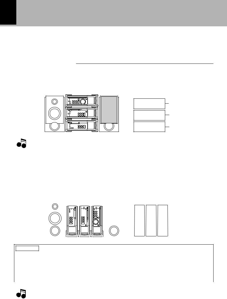
System configuration
The VH series system components can be installed either vertically on the sides (lengthwise) or horizontally by stacking one component on another. If you purchased the RD-VH7 alone, install it properly by also referring to the instruction manuals of the components to which it is connected.
RD-VH7 + DM-VH7+ X-VH7
(Amplifier-tuner/ CD player, MD recorder, Cassette deck )
(Horizontally stacked installation)
(Layout)
PREPARATION
RD-VH7
DM-VH7
X-VH7
With the horizontally stacked installation, be sure to use
Note the provided spacer. !
(Vertical, lengthwise installation)
Place each component so that its LCD comes at the bottom as shown
in the illustration. |
|
|
|
|
|
|
|
|
|
|
|
|
|
|
|
|
|
|
|
|
|
|
|
|
|
(Layout) |
|||||||
Be sure to change the feet before |
|
|
|
|
|||||||||||||||||||||||||||||
vertical installation. |
! |
|
|
|
|
|
|
|
|
|
|
|
|
|
|
|
|
|
|
|
|
|
|
|
|
||||||||
|
|
|
|
|
|
|
|
|
|
|
|
|
|
|
|
|
|
|
|
|
|
|
|
|
|
|
|
|
|
|
|
|
|
|
|
|
|
|
|
|
|
|
|
|
|
|
|
|
|
|
|
|
|
|
|
|
|
|
|
|
|
|
|
|
|
|
|
|
|
|
|
|
|
|
|
|
|
|
|
|
|
|
|
|
|
|
|
|
|
|
|
|
|
|
|
|
|
|
|
|
|
|
|
|
|
|
|
|
|
|
|
|
|
|
|
|
|
|
|
|
|
|
|
|
|
|
|
|
|
|
|
|
|
|
|
|
|
|
|
|
|
|
|
|
|
|
|
|
|
|
|
|
|
|
|
|
|
|
|
|
|
|
|
|
|
|
|
|
|
|
|
|
|
|
|
|
|
|
|
|
|
|
|
|
|
|
|
|
|
|
|
|
|
|
|
|
|
|
|
|
|
|
|
|
|
|
|
|
|
|
|
|
|
|
|
|
|
|
|
|
|
|
|
|
|
|
|
|
|
|
|
|
|
|
|
|
|
|
|
|
|
|
|
|
|
|
|
|
|
|
|
|
|
|
|
|
|
|
|
|
|
|
|
|
|
|
|
|
|
|
|
X-VH7
DM-VH7
RD-VH7
CAUTION Caution for Installation
To prevent fire hazard due to overheating, be sure to observe the information on this page when installing components horizontally by stacking them.
÷The RD-VH7 incorporates a ventilation fan and should always be stacked on the top of other components.
÷To avoid blocking heat radiation from the RD-VH7, do not place any object above it or behind the ventila-
|
tion hole on the rear panel. |
|
Top : 50 cm Back panel : 10 cm |
|
|
|
÷ Before changing the installation layout, be sure to take out the CD, MD and cassette tape from the |
Notes |
system components and unplug the power cords. |
÷Be careful not to tilt down the system components by mistake. Otherwise the CD, MD and/or cassette tape left in them may be damaged.
11
System configuration, Installation
RD-VH7/X-VH7 (EN)
Installation
When the components are to be installed horizontally for stacking, be sure to use the spacer for stacked installation which is provided with each component unit.
The front feet attached at the factory to each component unit of this series can be replaced with the provided replacement feet.
Installation accessories and installation precautions
Replacement front feet ............ 2 with each unit |
÷ Only the front feet can be replaced. |
|
Spacer for stacked installation |
|
Notes ÷ When attaching replacement front feet, use only |
................................. 1 with DM-VH7 and X-VH7 |
the screws which have been used with the re- |
|
Allen wrench ............................. 1 with each unit |
moved feet. (Using other screws may result in a |
|
|
|
fire or malfunction.) |
|
|
÷ Eject the CD, MD and/or tape and unplug the |
Changing the installation method |
power cord before installation. |
|
|
||
Horizontal, stacked installation |
|
Vertical installation |
Use the provided spacer for horizontal installa- |
Change the left front foot location as described |
|
tion. |
|
below. |
1Attach the spacer by inserting its claws into |
1Using the Allen wrench, remove the 2 |
|
the spacer mount holes on the rear of the |
screws from the front foot located on the |
|
DM-VH7/X-VH7. |
|
left when the unit is seen from the front. |
CAUTION When inserting the claws, align them |
2Align the removed front foot with the |
|
with the holes by tilting the spacer slightly (about 20 |
||
degrees) as shown in the illustration. |
|
threaded holes on the rear part of the right |
Spacer |
|
side panel, and attach the front foot using |
|
the screws removed in step 1. |
|
|
|
|
|
|
Step 2 |
claw |
Mount hole |
Step 1 |
|
||
2Arrange the cords by winding them around the spacer.
The audio cords and system control cord can be accommodated into the trench on the spacer by winding them as shown in the illustration.
Front feet removed in step 1
3Stack the component on this unit by align- |
|
|
ing the feet of the upper component with |
View of the unit when it is placed vertically |
|
the foot support cavities on the spacer. |
||
|
PREPARATION
How to replace the front feet
The factory-attached front feet can be exchanged |
Step 1 |
Step 2 |
with the provided replacement front feet. |
|
|
1Using the Allen wrench, remove the 4 screws from each front foot.
2Attach the provided replacement front feet.
Attach using two of the 4 screws removed in step 1.
Threaded holes
12 System connection
System connection
RD-VH7/X-VH7 (EN)
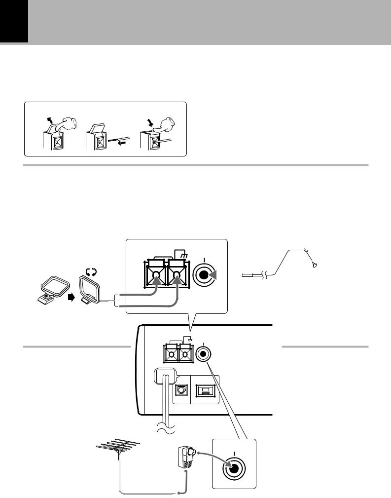
1. Connection of antenna
Connect the antenna as shown in the figure.
Do not plug the power cord into a wall AC outlet until the connection has been completed.
1 2 3
PREPARATION
Connection of the Accessory Antenna
AM loop antenna
The supplied antenna is for indoor use. Place it as far as possible from the main system, TV set, speaker cords and power cord, and set it to a direction which provides the best reception.
FM indoor antenna
The accessory antenna is for temporary indoor use only. For stable signal reception we recommend using an outdoor antenna. Remove the indoor antenna if you connect one outdoors.
ANTENNA |
GND |
AM |
FM 75Ω |
AM loop antenna
In case of bad reception
FM outdoor antenna
Lead the 75Ω coaxial cable connected to the FM outdoor antenna into the room and connect it to the FM 75Ω terminal.
GND
ANTENNA
AM |
FM 75Ω |
|
DIGITAL
OUT SYSTEM
OPTICAL CONTROL
FM indoor antenna
1 Plug into the terminal.
2Locate the position providing good reception condition.
3 Fix the antenna.
Amplifier-tuner/ CD player (RD-VH7)
(Commercially available)
FM 75Ω
FM outdoor antenna 
 (commercially available)
75Ω coaxial cable (Commercially available)
System connection 13
RD-VH7/X-VH7 (EN)
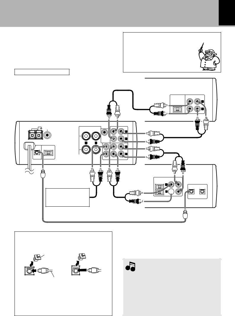
2. Connection of audio cord
Here, connection of separately sold components also will be explained under consideration of system connection. Please install correctly according to the purchased components and connect the required cords.
Caution for Connection
When connections are to be made, make sure that the power plug is not plugged into a wall AC outlet. Connect the equipment as shown in the figures.
Malfunction of microcomputer
If operation is not possible or erroneous display appears even though all connections have been made properly, reset the microcomputer referring to “In case of difficulty”. I
CassetteCassettedeckdeck
(X-VH7)X-VH7
Audio cord
(Supplied with X-VH7)
Amplifier-tuner/ CD player (RD-VH7)
ANTENNA |
GND |
|
|
|
REC OUT PLAY IN |
AM |
|
FM 75Ω |
SPEAKERS |
||
|
|
|
(6~16Ω ) |
|
|
|
|
|
|
L |
|
|
|
|
|
|
|
|
|
|
|
|
TAPE |
|
|
|
|
SUPER |
R |
|
|
|
|
WOOFER |
|
|
|
|
|
PRE OUT |
|
|
|
|
R |
L |
|
|
|
|
|
|
L |
|
|
|
|
|
MD |
DIGITAL |
|
|
|
|
R |
|
SYSTEM |
|
|
|
|
OUT |
|
|
AUX IN |
REC OUT PLAYIN |
|
OPTICAL |
CONTROL |
|
|||
Analog record turntable with built-in phono amp (P-110/ optional), VCR, etc. Audio cord
(Supplied with DM-VH7)
SYSTEM CONTROL |
REC |
PLAY |
|
IN |
OUT |
||
|
L
R
MD recorder (DM-VH7)
SYSTEM |
REC |
REC |
COMOROR |
IN |
OUT |
L
1 2
R 
DIGITAL IN
OPTICAL
PREPARATION
Connection with Optical Fiber Cable
RD-VH7 |
DM-VH7 |
Remove cap
Optical fiber cable
This is used for digital connections. Digital transmission permits recording without loss of the high CD sound quality.
Remove the cap and connect an optical fiber cable.
Optical fiber cable (Supplied with DM-VH7)
Notes
1.In case an associated system component is connected, also read the instruction manual of the component.
2.Insert the optical-fiber cable straight into the connector until it clicks.
3.Be sure to attach the protection cap when the connector is not used.
4.Be careful not to bend, coil or bundle the optical fiber cable.
14
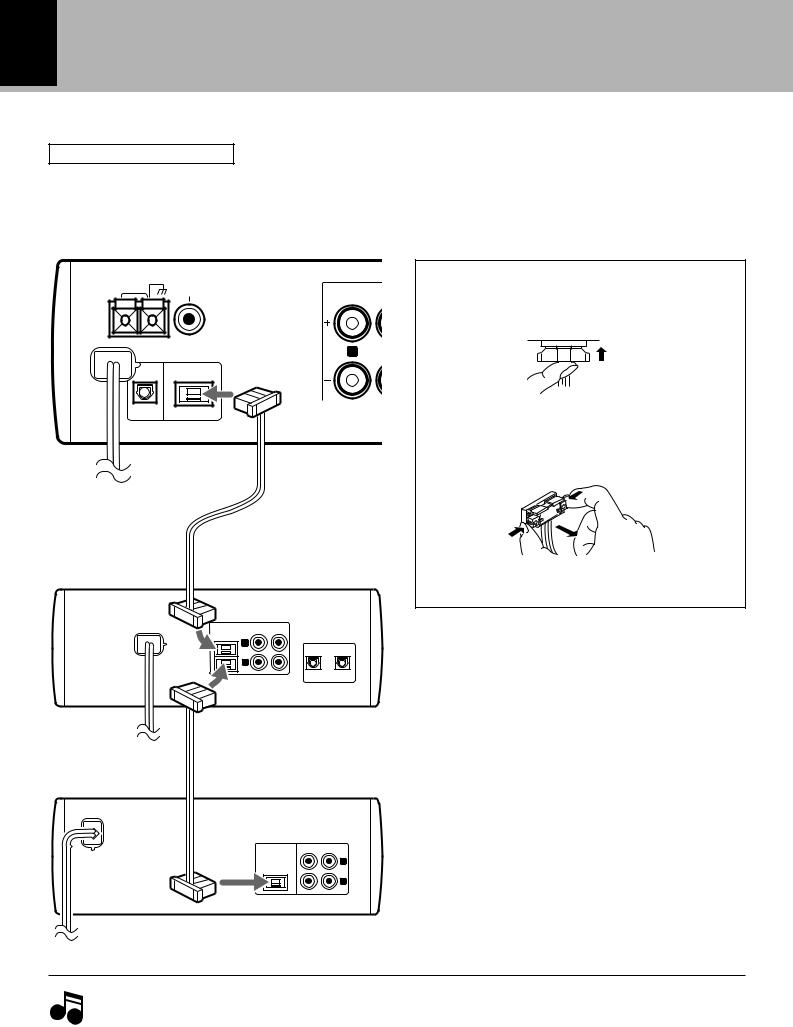
3. Connection of system control cord
System connection
RD-VH7/X-VH7 (EN)
Caution for Connection
When connections are to be made, make sure that the power plug is not plugged into a wall AC outlet. Connect the equipment as shown in the figures.
PREPARATION
Amplifier-tuner/ CD player (RD-VH7)
ANTENNA |
GND |
|
|
SPEAKERS |
|
AM |
FM 75Ω |
|
|
|
(6~16Ω ) |
R ¶
DIGITAL
OUT SYSTEM
OPTICAL CONTROL
To wall AC outlet
System control cord (Supplied with DM-VH7)
MD recorder (DM-VH7)
SYSTEM |
PLAY |
REC |
COMOROR |
IN |
OUT |
L
1 2
R
DIGITAL IN
OPTICAL
System control cord
(Supplied with X-VH7)
To wall AC outlet
Cassette deck (X-VH7)
SYSTEM CONTROL |
REC |
PLAY |
|
OUT |
IN |
||
|
L
R
Connection of system control cord
Plugging the connector
Insert straight until it clicks and locks.
Unplugging the connector
Push both ends of the connector to unlock it then pull it straight out.
To wall AC outlet
1. Be sure to insert all connection cords securely. If their connections are imperfect, the sound may not be pro-
Notes |
duced or noise may interfere. |
|
2.Before plugging or unplugging a connection cord, be sure to unplug the power cord from the wall AC outlet. If connection cords are plugged or unplugged with the power cord left plugged in, malfunction or damage may result.
System connection 15
RD-VH7/X-VH7 (EN)
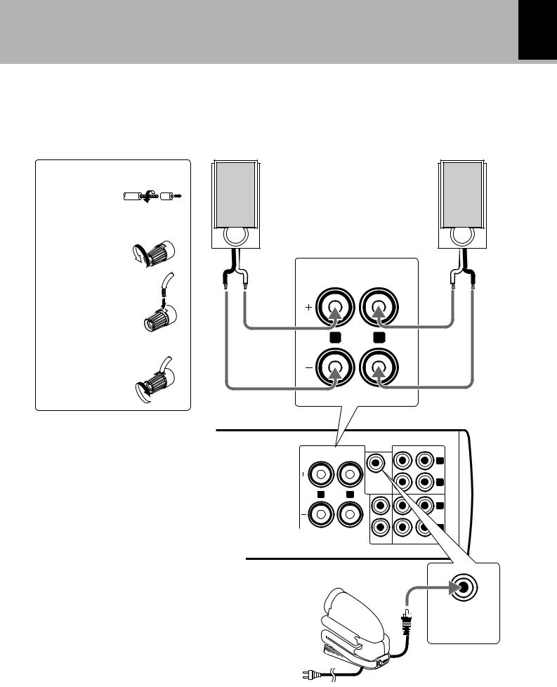
4. Connection of speakers
Connect the speakers as shown in the figure.
Do not plug the power cord into a wall AC outlet until the connection has been completed.
|
Speaker (Right) |
Speaker (Left) |
1Cord prepara- |
(6-16Ω) |
(6-16Ω) |
tion. |
|
|
2Loosen. |
· ª |
ª · |
SPEAKERS (6~16Ω )
3Insert.
R L
4Secure.
Amplifier-tuner/ CD player
(RD-VH7) |
SPEAKERS |
REC OUT |
PLAY IN |
(6~16Ω ) |
|
L |
|
|
|
||
|
|
|
|
|
|
|
TAPE |
|
SUPER |
|
R |
|
WOOFER |
|
|
|
PRE OUT |
|
|
R |
L |
|
|
|
|
|
L |
|
|
|
MD |
|
|
|
R |
|
AUX IN |
REC OUT |
PLAYIN |
PREPARATION
÷Never short-circuit the + and – speaker cords.
The protection circuit will operate and no sound will be put out.
÷If the left and right speaker connections or the + and
– polarity are inverted, the sound will be unnatural with unclear localization of musical instruments, etc. Be sure to connect them without mistake.
SUPER
WOOFER
PRE OUT
Super woofer (SW-500) (optional)
Extremely low frequency sound is played back powerfully.

16 Controls and indicators
Controls and indicators
RD-VH7/X-VH7 (EN)
Main Unit
Amplifier-tuner/ CD player |
|
|
|
|
(RD-VH7) |
|
|
|
|
1 |
^ |
% |
$ |
# |
|
stereo amplifier/tuner/CD RD-VH7 |
|
|
|
|
eject |
|
|
|
|
|
|
|
|
|
multi control |
mode |
|
|
|
|
|
|
|
|
|
|
|
|
|
|
|
|
|
|
|
|
|
2 |
|
|
|
input |
|
|
|
|
|
|
|
|
PREPARATION |
|
tuning |
p.call |
enter |
|
|
|
|
|
|
on/standby |
|
|
3 |
standby |
band |
|
|
|
|
|
|
|
|
|
||
timer |
|
|
|
|
|
|
|
|
|
||||
|
|
|
|
|
|
|
|
|
|
||||
|
phones |
|
|
|
|
|
|
|
|
|
|
||
|
|
auto |
|
stop |
|
|
|
|
|
|
|
||
|
|
/mono |
|
|
|
|
|
|
|
|
|||
|
|
|
|
|
|
|
|
|
|
|
|||
|
|
demo |
|
|
|
|
|
|
|
|
|
||
|
|
|
|
|
|
|
|
|
|
|
|
||
|
|
4 5 6 7 890 |
! |
|
|
|
@ |
|
|
|
|||
|
|
|
|
|
|
|
on/standby |
|
|
|
|
power |
on/standby |
|
Cassette deck |
|
|
|
|
|
|
|
|
|
|
|
|
|
(X-VH7) |
|
|
|
|
|
U.K. and Europe |
|
|
|
|
U.S.A. |
|
|
|
|
|
|
|
|
|
|
|
|
|||
|
1 |
|
$ |
|
|
|
|
|
|
|
|
# |
|
|
|
|
auto reverse cassette deck X-VH7 |
|
|
|
|
|
|
|
|
||
|
eject |
|
|
|
|
|
|
|
|
|
|
|
|
|
|
|
tape loading mechanism |
|
|
|
|
|
|
|
|
|
|
|
|
|
|
|
|
|
function indicator |
|
|
||||
|
2 |
recording |
|
|
|
Dolby NR |
|
direction |
|
|
|||
|
|
|
|
|
|
-type |
-type |
reverse forward |
on/standby |
||||
|
|
|
|
|
|
|
|||||||
|
|
|
|
|
|
|
B |
C |
|
||||
|
3 |
standby |
|
|
crls |
pause |
fwd |
|
ode |
|
|||
|
|
|
|
|
pause |
||||||||
|
|
|
|
|
|
.m |
|
|
|||||
|
|
|
|
|
|
|
|
crls |
|
|
|||
|
|
|
|
|
|
|
rev |
|
|
|
|
||
|
|
rev.mode |
Dolby NR |
|
|
|
|
|
|
|
|
|
|
|
|
|
|
|
rec |
stop |
rev |
|
|
|
|
|
|
|
|
|
|
|
/arm |
|
|
|
|
|
|
||
|
|
4 5 |
|
678 90 ! |
|
|
@ |
|
|
|
|||
|
Standby mode |
|
|
|
|
|
|
|
|
|
|
|
|
While the standby indicator of the unit is lit, a small amount of current is flowing into the unit’s internal circuitry to back up the memory. This condition is referred to as the standby mode of the unit. While the unit is in the standby mode, it can be turned ON from the remote control unit.

17
Controls and indicators
RD-VH7/X-VH7 (EN)
Amplifier-tuner/CD player (RD-VH7)
1“0eject” key
The key lights in blue when a CD is loaded inside.
2“standby/timer” indicator |
p,E |
When power is ON |
:Not lit. |
When power is OFF (standby) |
:Lights in red. |
During timer standby |
:Lights in green. |
3Remote sensor |
|
4“phones” jack |
£ |
Plug headphones with a stereo mini-plug (optional).
5“auto/mono, demo” key
Press to switch the demonstration mode ON and OFF.
4
Press to switch the tuning mode when receiving radio.
fi
6“band” key
When power is OFF (standby):
Press to turn the system power ON and start radio
reception on the tuner. |
™ |
When power is ON: |
›,fi |
Press to select the tuner input. |
|
During tuner reception: |
›,fi |
Press to switch the radio band. |
|
7“tuning 1, ¡” keys |
|
During CD playback: |
|
Press to fast forward or fast reverse the track being
played. |
¶ |
During tuner reception: |
|
Press to select a radio station. |
fi |
8“p.call 4, ¢” keys |
|
During CD playback: |
|
Press to skip CD tracks. |
¶ |
During tuner reception: |
|
Press to select a preset radio station. |
› |
9“7 stop” key
When power is OFF (standby):
Press to display the time of the day for 5 seconds.
|
¡ |
During CD playback: |
|
Press to stop playback. |
¶ |
0“enter, 6” key |
|
During operation mode setting: |
|
Press to set an entry. |
|
When power is OFF (standby): |
|
Press to turn the system power ON and start CD
playback. |
™ |
When CD input is selected: |
|
Press to start playback or let it pause. |
¶ |
!“multi control” knob ¡,™,°,p
This knob is usually used to adjust the listening volume but can also be used in setting selection, timer reservation and clock adjustment operations.
@Character data display
#“ 

 on/standby, (power on/standby)” key
™,p,E
Press to switch the power ON and OFF (standby). When system components are connected through system control cords, press to turn the entire system power ON and OFF.
$“mode” key |
¡,¢,° |
Press to initial a setting/selection mode. |
|
%CD insertion slot |
™,r |
^“input” key |
|
Press to select an input source.
When TAPE, CD or MD is selected, the corresponding component starts to play automatically provided that a tape or disc has already been loaded in it.
PREPARATION
Cassette deck (X-VH7)
1“0 eject” key |
‚ |
8“1, ¡” keys |
q~e |
The key lights in blue when a cassette tape is loaded |
Press to fast forward or rewind tape. |
||
inside. |
|
9“8 pause” key |
q,t |
2“recording” indicator |
t |
Press to let playback or recording pause temporarily. |
|
3“standby” indicator |
|
0“7 stop” key |
q,t,u~o |
When power is ON |
:Not lit. |
When power is OFF (standby) :Lights in red. |
|
4“rev. mode” key |
q,t |
Press to switch the reverse mode (two-way, one-way) of the cassette deck.
5“Dolby NR” key |
q,t |
Press to switch the Dolby Noise Reduction on/off and its type.
6“crls” key |
y |
Press to set the recording level automatically according to the recording source.
7“¶ rec/arm” key |
t |
Press to start recording. Pressing during recording stops it after leaving a non-recorded space (blank) of about 4 seconds.
Press to stop an operation.
!“2 rev, 3fwd” keys ‚~r
Press to play a cassette tape. When power is OFF (standby):
Press to turn the system power ON and start cassette tape playback.
@“function indicator” |
‚~y |
Press to display the playback/ recording conditions including the Dolby NR mode, tape direction, reverse mode, etc.
#“ 

 on/standby, (power on/standby)” key
Press to switch the power ON and OFF (standby). When system components are connected through system control cords, press to turn the entire system power ON and OFF.
$Cassette insertion slot
18
Controls and indicators
RD-VH7/X-VH7 (EN)
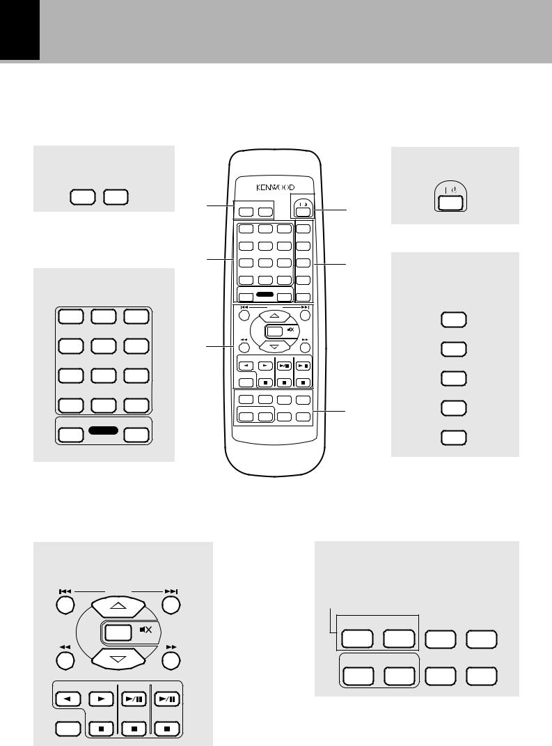
Remote control Unit
When the system control cord is connected, this remote control can be used to operate the entire system. The keys on the remote control unit with the same names as on the main unit have the same function as the keys on the main unit.
1Timer-related keys
|
SLEEP |
TIMER |
|
|
|
|
|
|
|
|
|
|
|
|
|
|
|
|
|
|
|
|
|
POWER |
|
|
|
|
|
1 |
SLEEP |
|
|
|
TIMER |
|
|
4 |
|
|
|
|
|
|
|
|
|
|
|
REPEAT |
|
|
|
|
|
|
1 |
|
|
|
2 |
3 |
|
|
|
|
|
|
|
|
|
|
|
|
|
RANDOM |
|
PREPARATION |
|
|
|
|
4 |
|
|
|
5 |
6 |
|
|
|
|
|
2 |
|
|
|
|
P.CALL |
P.MODE |
5 |
||
|
|
|
|
7 |
|
|
|
8 |
9 |
|
||
|
|
|
|
|
|
|
|
|
||||
|
2Numeric/ O.T.E. keys |
|
|
|
|
|
|
|
CHECK |
|
||
|
|
+10 |
|
|
|
0 |
+100 |
|
|
|||
|
|
|
|
|
TAPE |
|
|
|
O.T.E. |
MD |
CLEAR |
|
|
|
|
|
|
|
|
|
|
|
|
|
|
|
1 |
2 |
3 |
|
|
|
|
|
L |
|
|
|
|
|
|
|
|
|
|
R |
O |
|
|
|
|
|
|
|
|
|
|
T |
|
|
|
|
||
|
|
|
|
|
N |
|
|
|
|
|
||
|
|
|
|
|
|
|
|
|
|
|
||
|
|
|
|
|
O |
|
|
|
|
|
|
|
|
|
|
|
|
C |
|
|
|
|
MUTE |
|
|
|
|
|
|
|
M |
|
|
|
||||
|
|
|
|
|
E |
|
|
|
|
|
|
|
|
|
|
|
|
U |
|
|
|
|
|||
|
|
|
|
3 |
|
L |
|
|
|
|||
|
|
|
|
|
|
|
O |
|
|
|
||
|
4 |
5 |
6 |
|
|
|
|
V |
|
|
|
|
|
|
|
|
|
|
|
|
|
||||
|
|
|
|
|
TAPE |
MD |
CD |
|
||||
|
7 |
8 |
9 |
|
INPUT |
|
|
|
|
|
|
|
|
|
|
|
|
TA/NEWS |
|
|
PTY |
AUTO/MONO TUNER/BAND |
|
||
|
+10 |
0 |
+100 |
|
DISPLAY |
|
|
MEMORY |
TONE |
N.B. |
6 |
|
|
|
|
|
|
|
|
||||||
|
TAPE |
|
MD |
|
|
|
|
|
|
|
|
|
|
O.T.E. |
|
|
REMOTE CONTROL UNIT |
|
|||||||
RC-RP0702E
Model: |
|
For U.K. and Europe ................. |
RC-RP0702E |
For U.S.A. and U.S. military .... |
RC-RP0702 |
4POWER key
POWER
5CD play mode/ pro- gram-related keys
REPEAT
RANDOM
P.MODE
CHECK
CLEAR
3Basic operation/ input selec- tion-related keys
P.CALL
|
|
R |
O |
L |
|
|
|
T |
|
|
|
||
N |
|
|
|
|
||
|
|
|
|
|
||
|
|
|
|
|
|
|
O |
|
|
|
|
|
|
C |
|
|
|
|
MUTE |
|
E |
|
|
|
|
||
M |
|
|
|
|||
U |
|
|
|
|||
|
L |
|
|
|||
|
|
|
O |
|
|
|
|
|
|
|
V |
|
|
TAPE |
MD |
CD |
||||
6Tuner/ RDS operation, tone adjustment and display switching-related keys
RC-RP0702E only
TA/NEWS |
PTY |
AUTO/MONO TUNER/BAND |
|
DISPLAY |
MEMORY |
TONE |
N.B. |
INPUT

1Timer-related keys
“SLEEP” key |
R |
Press to set the sleep timer. |
p, R |
“TIMER” key |
Press to execute or cancel a timer program.
2Numeric/ O.T.E. key
Numeric keys
When CD or MD input is selected:
Press to enter numbers. ¶ During tuner reception:
Press when recalling a preset radio station.
“O.T.E.” (One-Touch Edit) key |
›,‡ |
|
|
This key is also used when programming tracks in a |
|
desired sequence and recording them. |
u |
Press during CD playback to record the currently play- |
|
ing track onto a cassette tape or MD. |
i |
Press during stop to record a CD from track number 1. o
3Basic operation/ input selection-related keys
“4, ¢” keys
When the CD or MD input is selected:
Press to skip tracks. ¶ During tuner reception:
Press to select a radio station. ›,‡,·
“1, ¡” keys
During CD or MD playback:
Press to fast forward or fast reverse the disc. ¶ During tuner reception:
Press to select radio stations. fi When the TAPE input is selected:
Press to fast forward or rewind the cassette tape. q
“VOLUME CONTROL” key ™,£
Press to adjust the listening volume or tone.
MD control keys (6, 7)
Press to control the MD recorder (DM-VH7).
CD control keys (6, 7)
|
¶, º, ¤, ‹ |
Press to control the CD player. |
|
Cassette deck control keys (2, 3, 7) |
|
These keys are used to control the cassette deck (X- |
|
VH7). |
‚, q, r, t |
“MUTE” key |
£ |
Press to mute sound temporarily. |
|
“INPUT” key |
™, r |
Press to select an input source.
When TAPE, CD or MD is selected, the corresponding component starts to play automatically provided that a tape or disc has already been loaded in it.
19
Controls and indicators
RD-VH7/X-VH7 (EN)
4POWER key
“ 

 POWER” key ™,p,E
Press to switch the power of the amplifier-tuner/CD player (RD-VH7) ON and OFF (standby). When system components are connected through system control cords, press to turn the entire system power ON and OFF. This key is also used in timer programming.
5CD play mode/ program-related keys
“REPEAT” key |
¤ |
Press for repeat playback of a CD. |
|
“RANDOM” key |
‹ |
Press to play the tracks in a CD in a random order.
“P.MODE” key |
º, ⁄ |
PREPARATION |
playback. |
|
|
Press when programming CD tracks for program play- |
|
|
back or program recording. |
|
|
“CHECK” key |
⁄ |
|
Press to check the tracks programmed for CD program |
|
|
“CLEAR” key |
⁄, u |
|
Press to clear the last track from the programmed CD tracks.
6Tuner/ RDS operation, tone adjustment and display switching-related keys
“TA/NEWS”, “PTY” key (RC-RP0702E only)
‡, °
Press to switch the modes during RDS broadcast reception.
“AUTO/MONO” key |
fi |
Press to switch the tuning mode of the tuner.
“TUNER/BAND” key ›, fi
Press to select the tuner input.
This key is also used to switch the broadcast bands.
“DISPLAY” key |
•, fl |
Press to switch the displayed information on the am- plifier-tuner/CD player (RD-VH7).
“MEMORY” key |
fi |
Press when presetting radio stations. |
|
“TONE” key |
£ |
Press to adjust the highest and lowest frequencies.
“N.B.” (Natural Bass) key |
£ |
Press to compensate for the tone.
20 Operation of remote control unit
Controls and indicators
PREPARATION
RD-VH7/X-VH7 (EN)
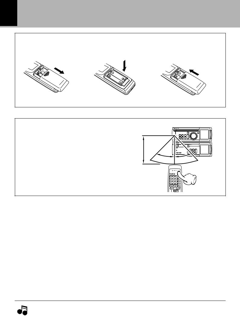
Loading batteries
1Remove the cover. |
2Insert batteries. |
3 Close the cover. |
÷Insert two R6 (“AA”-size) batteries following the polarity indications.
Operation
Plug the power cord into a power outlet and press the “ 

 POWER” key on the remote control unit to switch the power ON. Then press the key of the function you want to control.
Operating range (approx.)
Remote sensor
6m
30˚ 30˚
30˚
POWER
|
SLEEP |
TIMER |
|
|
|
|
REPEAT |
|
1 |
2 |
3 |
|
|
|
RANDOM |
|
4 |
5 |
6 |
÷ When pressing more than one remote control keys |
|
|
P.MODE |
7 |
8 |
9 |
|
TAPE |
|
MD CLEAR |
|
|
|
|
CHECK |
|
+10 |
0 |
+100 |
successively, press the keys securely by leaving an |
|
O.T.E. |
|
|
P.CALL |
||
interval of 1 second or more between keys. |
E |
|
MUTE |
|
MU |
|
|
|
1. |
The provided batteries are intended for use in operation checking, and their service life may be short. |
Notes |
2. |
When the remote controllable distance becomes short, replace both of the batteries with new ones. |
|
|
3.If direct sunlight or the light of a highfrequency fluorescent lamp (inverter type, etc.) is incident to the remote sensor, malfunction may occur. In such a case, change the installation position to avoid malfunction.
 Loading...