


TS-850S
Table of contents
 Loading...
HF TRANSCEIVER
TS-850S
INSTRUCTION MANUAL
KENWOOD CORPORATION
©PRINTED IN JAPAN B62-0061-10(K, X)(T)
92/12 1110 987654321 91/12 1110 9 8 7 6 5

Thank you for purchasing this new transceiver.
IMPORTANT
Please read this Instruction Manual carefully before
placing the transceiver in service.
SAVE THIS INSTRUCTION MANUAL
The following explicit definitions apply in this manual:
Note ; If disregarded, inconvenience only, no
risk of equipment damage or personal
injury.
Caution : Equipment damage may occur, but not
personal injury.
This Instruction Manual covers the TS-850S, with
and without AT (Automatic Antenna Tuner) unit.
When there are differences in operation, separate
instructions will be given for each model.
Illustrations show the TS-850S with AT unit.
Notice to the user:
One or more of the following statements may be
applicable to this equipment.
FCC WARNING
This equipment generates or uses radio frequency
energy. Changes or modifications to this
equipment may cause harmful interference unless
the modifications are expressly approved in the
instruction manual. The user could lose the
authority to operate this equipment if an
unauthorized change or modification is made.
Information to the digital device user required by
the FCC:
This equipment has been tested and found to
comply with the limits for a Class B digital device,
pursuant to Part 15 of the FCC Rules. These limits
are designed to provide reasonable protection
against harmful interference in a residential
installation. This equipment generates, uses and
can generate radio frequency energy and, if not
installed and used in accordance with the
instructions, may cause harmful interference to
radio communications. However, there is no
guarantee that the interference will not occur in a
particular installation. If this equipment does cause
harmful interference to radio or television
reception, which can be determined by turning the
equipment off and on, the user is encouraged to
try to correct the interference by one or more of
the following measures:
Reorient or relocate the receiving antenna.
Increase the separation between the
equipment and receiver.
Connect the equipment into an outlet on a
circuit different from that to which the
receiver is connected.
Consult the dealer for technical assistance.
_____
CONTENTS
1. BEFORE OPERATION
2. SPECIFICATIONS AND ACCESSORIES
2-1. SPECIFICATIONS
2- 2. ACCESSORIES ..........................................6
3. INSTALLATION AND CONNECTION..................7
3- 1. INSTALLATION
3- 2. CONNECTION
4. OPERATION .....................................................10
4- 1. OPERATING CONTROLS .......................10
4-2. INITIAL SETTING ........................................19
4-3. SSB OPERATION
4-4. CW OPERATION
4-5. FM OPERATION ..........................................25
4-6. AM OPERATION ..........................................26
4-7. FSK OPERATION
4-8. PACKET (AFSK) OPERATION
4-9. AUTO ANTENNA TUNER OPERATION
4-10. OTHER OPERATION ................................31
4-11. MEMORY
4-12. SCAN
4-13. DRS FUNCTION
4-14. REPEATER OPERATION ..........................45
4-15. OPERATION WITH A PERSONAL
COMPUTER
4-16. VOICE SYNTHESIZER
4-17. DIGITAL MODULATION FUNCTION
4-18. Transfer function when two TS-850S
transceivers are connected together
4-19. When used as the master machine for the
transverter .................................................49
4- 20. Remote control function..........................51
5. CIRCUIT DESCRIPTION
5- 1. BLOCK DIAGRAM
5- 2. CIRCUIT DIAGRAM
6. MAINTENANCE AND ADJUSTMENTS.............62
6- 1. GENERAL INFORMATION
6-2. SERVICE ......................................................62
6-3. CLEANING ...................................................62
6-4. IN CASE OF DIFFICULTY
6-5. ORDERING SPARE PARTS.........................64
6- 6. ADJUSTMENTS
7. OPTIONAL ACCESSORIES
7- 1. FILTER INSTALLATION ...........................67
7-2. VS-2 VOICE SYNTHESIZER
INSTALLATION
7-3. DRU-2 DIGITAL RECORDING UNIT
INSTALLATION
7-4. SO-2 TCXO UNIT INSTALLATION
7-5. DSP-100 DIGITAL SIGNAL PROCESSOR
CONNECTION ............................................69
7-6. TL-922/922A LINEAR AMPLIFIER
CONNECTION ............................................69
7-7. SM-230 STATION MONITOR
INSTALLATION
7-8. AT-850 AUTOMATIC ANTENNA TUNER
UNIT INSTALLATION .................................70
7-9. AT-300 AUTOMATIC ANTENNA TUNER
CONNECTION ............................................70
7-10. OTHER ACCESSORIES ...........................71
8. REFERENCE
...................................................
...........................................................
....................................................
.......................................
...........
.........................................
..........................................
...........................................
........................................
.........................................
........................................
.....................
........
........................................
.............................................
..............................
.........
...........
..................................
...................................
.................................
.......................
...........................
.......................................
.............................
..........................................
..........................................
...............
..........................................
20
22
27
28
37
43
46
46
46
52
52
53
62
63
64
67
67
68
68
69
73
3
4
4
7
7
30
41
47
1.
BEFORE OPERATION
TO PREVENT ELECTRIC SHOCK, FIRE AND OTHER INJURY. PLEASE NOTE THE
FOLLOWING:
V - !
Do not place this unit, where it will be exposed to
direct sunlight or close to heating appliances.
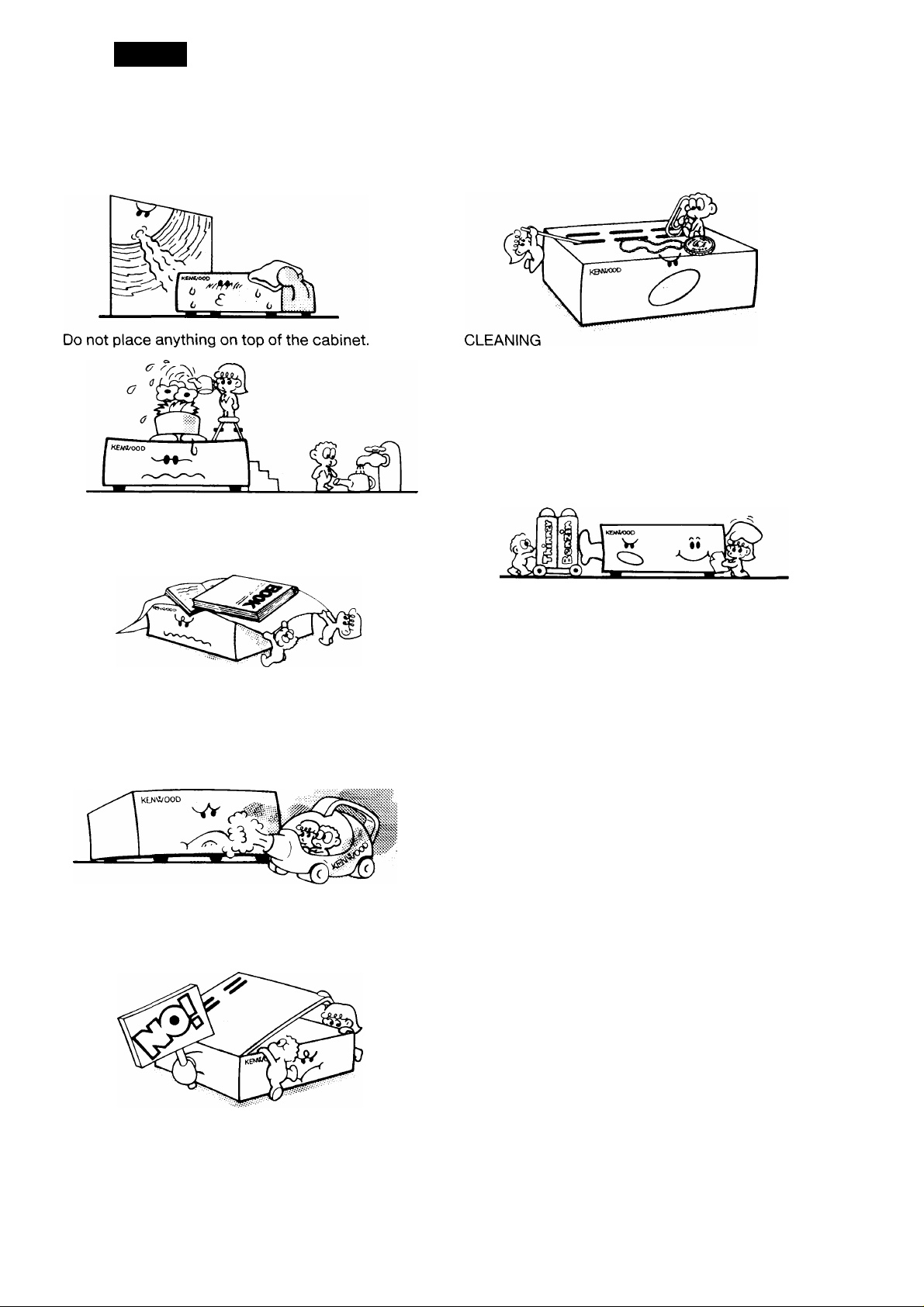
To ensure good ventilation, do not put anything on
top of the cabinet and allow at least 15 cm (6
inches) of space behind the unit.
Do not drop pieces of metal, needles, coins and
other electrically conductive materials into the unit.
1. Turn the power off, before cleaning the unit.
2. Do not use any type of abrasive pad, thinner,
benzine or any substances which may damage
the unit.
3. Wipe the front panel and other exterior surfaces
of the unit with a soft dry cloth or a soft cloth
lightly moistened with water.
Do not place the unit in areas of excessive dust,
high humidity or on unstable surfaces.
v'-X
To avoid risk of electric shock, under no
circumstances should the unit be opened:
2. SPECIFICATIONS AND ACCESSORIES
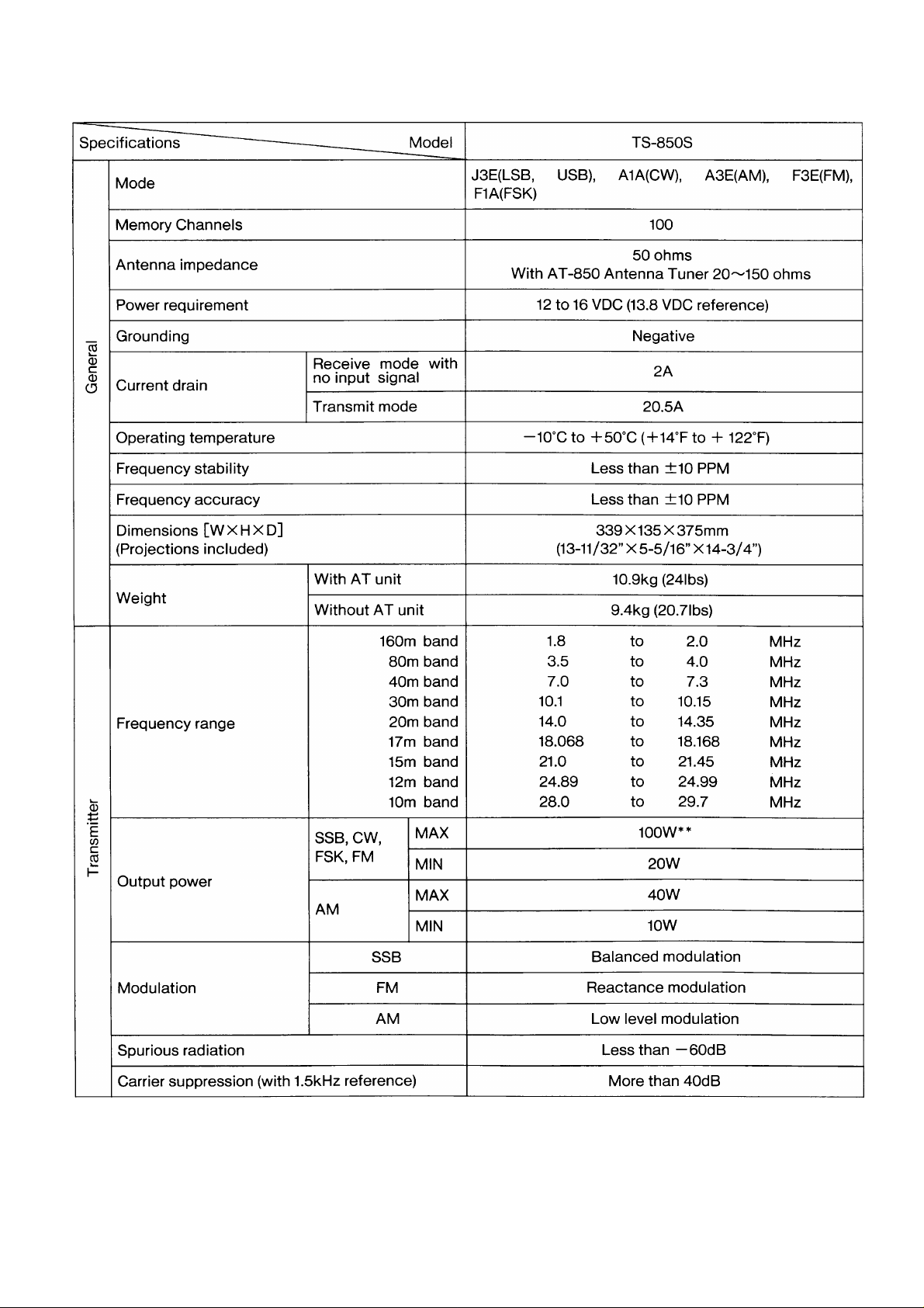
2-1. SPECIFICATIONS
Specifications
----
Model
TS-850S
CT3
Unwanted sideband suppression (with 1.5kHz
reference)
Maximum frequency deviation (FM)
o
E
Frequency response (—6dB)
CO
I-
Ai 1 vanaoie range
10 Hz step
20 Hz step
Less than ±5kHz
More than ±1.2kHz
More than ±2.4kHz
Microphone impedance 600n
Circuitry
Frequency range
Intermediate frequency
SSB, CW,
FSK
(at lOdB S
100kHz~500kHz
500kHz~1.62MHz*
*1.62MHz~24.5MHz
Triple conversion superheterodyne
100kHz to 30MHz
1st; 73.05MHz, 2nd : 8.83MHz, 3rd : 455kHz
Less than 0.2 //V
Less than 0.2 pc\/
+ N/N)
Sensitivity
AM
24.5MHz~30MHz
100kHz~500kHz Less than 2 //V
500kHz~1.62MHz* Less than 32 /^V
Less than 0.13 //V
(at lOdB S
+ N/N)
*1.62MHz~24.5MHz
More than 40dB
400 to 2600Hz
Less than 4 //V
Less than 2
0)
>
■(D
O
CD
CC
Selectivity
Image ratio
1st IF rejection
Notch filter attenuation
HM vanaoie range
Squelch
sensitivity
Output
FM
(at12dBSINAD)
SSB, CW,
FSK, AM
FM
24.5MHz~30MHz Less than 1.3//V
28MHz~30MHz
SSB, CW, FSK
AM
Less than 0.25 //V
-6dB:2.4kHz, -60dB:3.8kHz
-6dB:6kHz, -60dB;15kHz
FM -6dB:12kHz, -60dB:24kHz
More than 80dB
More than 80dB
More than 40dB
10 Hz step
20 Hz step
100kHz~500kHz
500kHz~1.62MHz*
♦1.62MHz~30MHz
28MHz~30MHz
More than ±1.2kHz
More than ± 2.4kHz
Less than 2 //V
Less than 20 /uV
Less than 2 ;c^V
Less than 0.25 //V
1.5W across 8 ohms load (10% distortion)
Output load impedance
8 ohms
Notes
1. Circuit and ratings are subject to change without notice due to advancements in technology.
2. Remember to keep the transmit output power within the power limitations of your license.
3. *: The U.S.A. version is 1.705 MHz.
4. **: With auto antenna tuner in “THRU” or bypass position.

2-2. ACCESSORIES
Unpack your TS-850S carefully and confirm that it is supplied with the following accessories.
Dynamic microphone
DIN plug (7-pin) ................................................................E07-0751-05
DIN plug (13-pin) ..............................................................E07-1351-05
DC power cable assembly
Calibration cable
Fuse (25A)
Fuse (3A)
External control Instruction Manual
Instruction Manual ................................................................B62-0061-XX ...........................1 copy
Warranty card (U.S.A., Canada and Europe version only) ........................................................1 ea.
After unpacking
Shipping container:
Save the boxes and packing in the event your unit needs to be transported for remote operation, maintenance,
or service.
...........................................................................
.............................................................................
...........................................................
...................................................
..................................................................
.....................................
T91-0352-15
E30-3035-05 ................................1 ea.
E31-2154-05
F51-0011-05
F06-3026-05 ................................1 ea.
B62-0065-XX ...........................1 copy
.............................
...............................
.............................
.............................
.............................
1 ea.
lea.
1 ea.
lea.
lea.
3. INSTALLATION AND CONNECTION
3-1. INSTALLATION
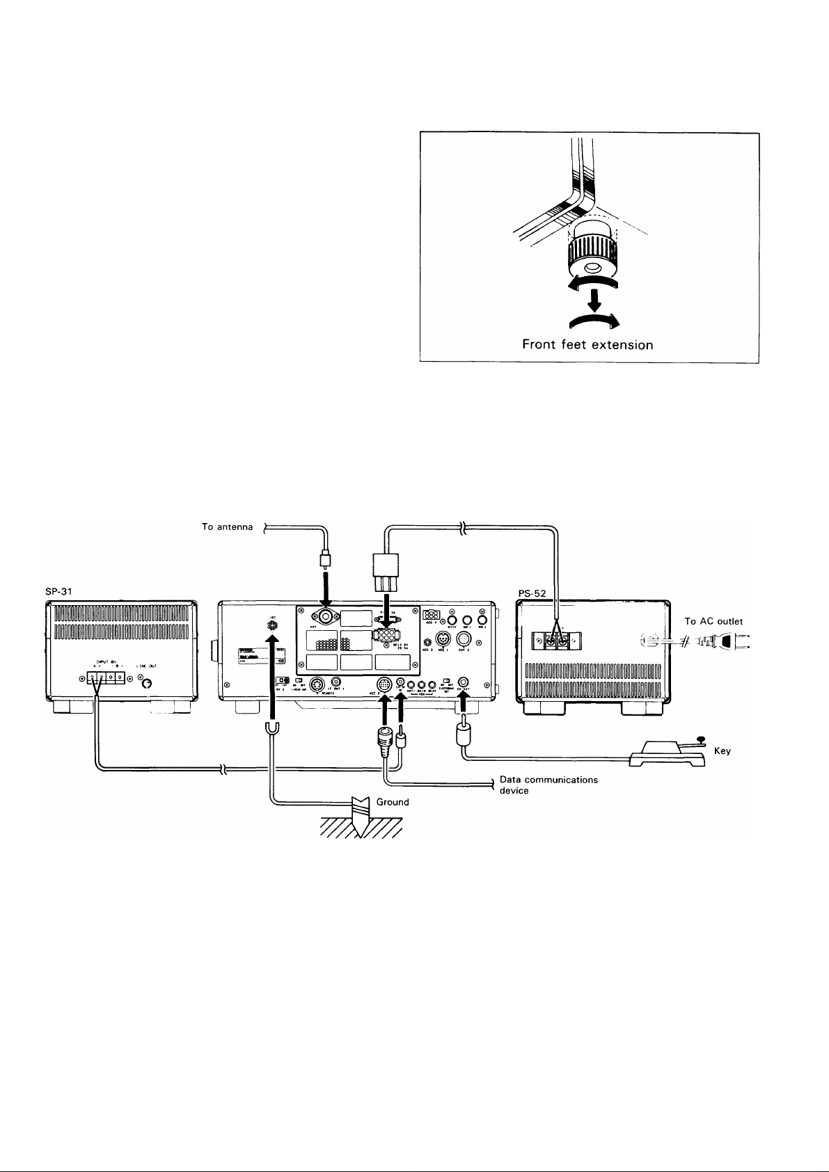
■FRONT FEET
By extending the front feet, the front panel can be
elevated for operating convenience.
Turn the front foot left and pull down.
Then turn right to lock.
3-2. CONNECTION
The TS-850S requires more than 20.5 A at 13.8 VDC
when transmitting at full power. Use the PS-52 power
supply for fixed station operation.
A. Rear Panel

(1) Antenna (4) Key connection
Caution
Protect your equipment — Use a LIGHTNING
ARRESTER.
The type of antenna that is used will greatly affect
the performance of the transceiver. Use a properly
adjusted antenna, of good quality, to enable your
transceiver to perform at its best. The antenna input
impedance is 50 ohms. Use 50-ohm coaxial cable
such as 5D-2V or RG-213/U (RG-8A/U) for this
connection. If the antenna is far from the transceiver
the use of low loss coaxial cable, such as 5D-2V or
RG-213/U (RG-8A/U) are recommended. Match the
impedance of the coaxial cable and that of the
antenna so that the SWR is less than 1.5 to 1. The
protection circuit in the transceiver will activate if the
SWR is particularly poor (greater than 3 to 1). High
SWR value will cause transmitter output to drop, and
may lead to TVI or BCI reports.
(2) Grounding
Caution
Never use a gas pipe or electrical conduit pipe.
Notes
1. A ground connection that is a 1/4 wavelength or
its multiple may provide a good DC ground, but
it will not provide a good RF ground.
2. A city water pipe cannot be used as a good
earth in some cases.
Your key should be connected as illustrated in the
figure below. When using an electronic keyer, make
sure that polarity is set for positive. Always use
shielded line from the key to transceiver, (diameter
6.0 mm)
|To use external straight key
+5V, Contact
Current about 1
mA
Ground Not used +
or
Ground +
Note
Check the polarity of the plug when you use an
electronic keyer.
Please refer to Section 4-4.
-I-5V, Contact
Current about 1
mA
Making a good earth connection is important for
preventing dangers such as electric shock and for
emitting a high quality signal with minimum spurious
radiation. Bury a commercially available ground rod
or copper plate under the ground and connect it to
the GND terminal. A thick wire, cut as short as
possible, should be used for the connection. To
make a good earth connection, connect the GND
terminal to a grounded metal water pipe.
(3) External speaker
The TS-850S includes a built-in speaker. If you
would like to use an external speaker, such as the
SP-31, it may be connected to the EXT SP jack on
the rear of the transceiver. The speaker may be any
good 8 ohm permanent magnet type speaker. The
diameter should be at least 4 inches for good audio
quality. If you plan on using a speaker other than the
SP-31 it should be equipped with a miniature phone
jack plug, (diameter 3.5 mm)
8
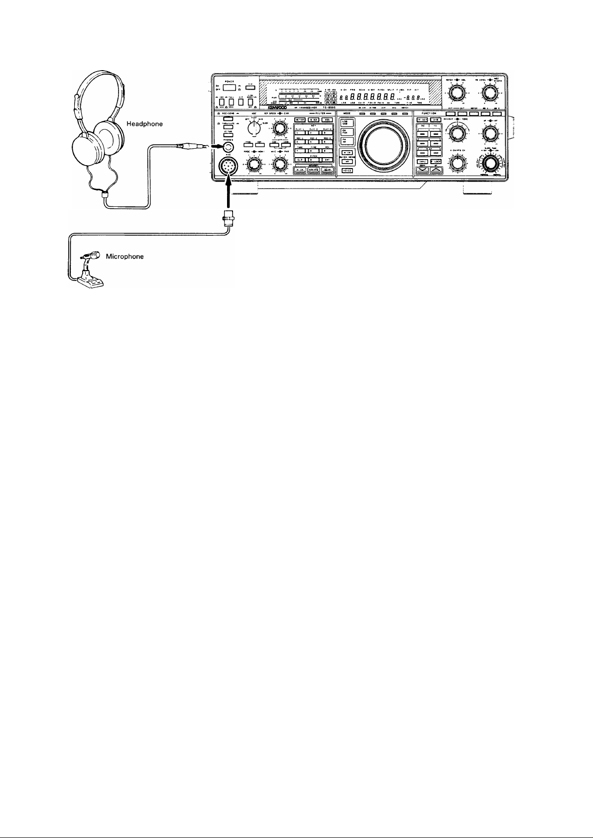
B. Front Panel
(1) Headphones
Any low-impedance (4-16 ohms) headphone may be
used with the transceiver. Connect the headphones
to the front panel PHONES jack, (diameter 6.0 mm).
The optional HS-5 or HS-6 headphones are best
suited for use with the transceiver. Stereo type
headphones can also be used.
(2) Microphones
Any microphone with an impedance to 6000 may be
used with this transceiver. The KENWOOD
microphones MC-43S (handheld), MC-60A, MC-80,
MC-85 (table-top type) are recom-mended.
4. OPERATION
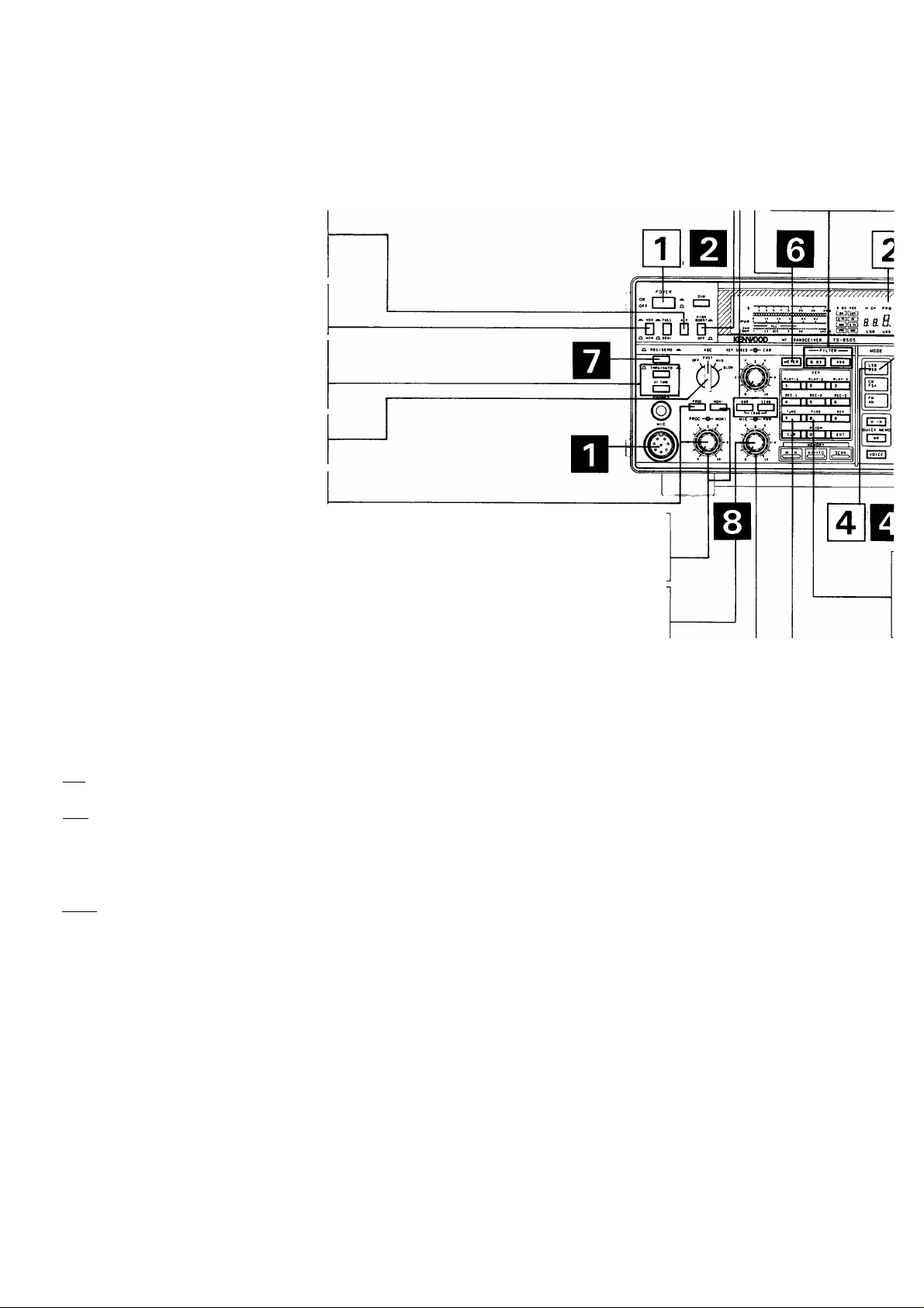
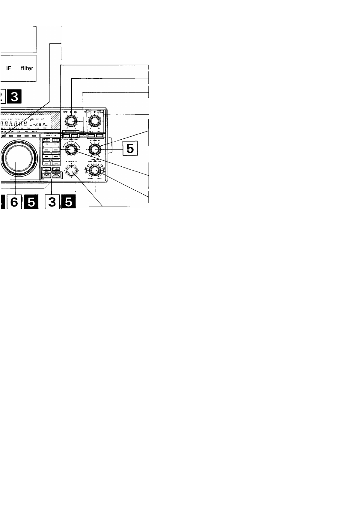
4-1. OPERATING CONTROLS 4-1-1. Front Panel
P.10
I I: cb
L vox A FULL AlP eOO$T.a
□ □ □ □
HIGH
GCDOocoooaaooooocooaocooacxxxic
-J_—1-
«OOOyCIOr>y>OO^yiOOOOOO^^^ I gTf ] riiS~]
KBNKXX3 Hf TBAWScetVEB TS-850S
.. .. . rmnn
P.12 P.13
ri»HTtn
P.11
PPO SCAN
a tt
Lse USB cv-R
Note
All segments on the Display Panel and Indicators
are shown on for this explanation.
P.12
NOTCH SQL NB LEVEL •
i .H. -a a a.H.
P.14
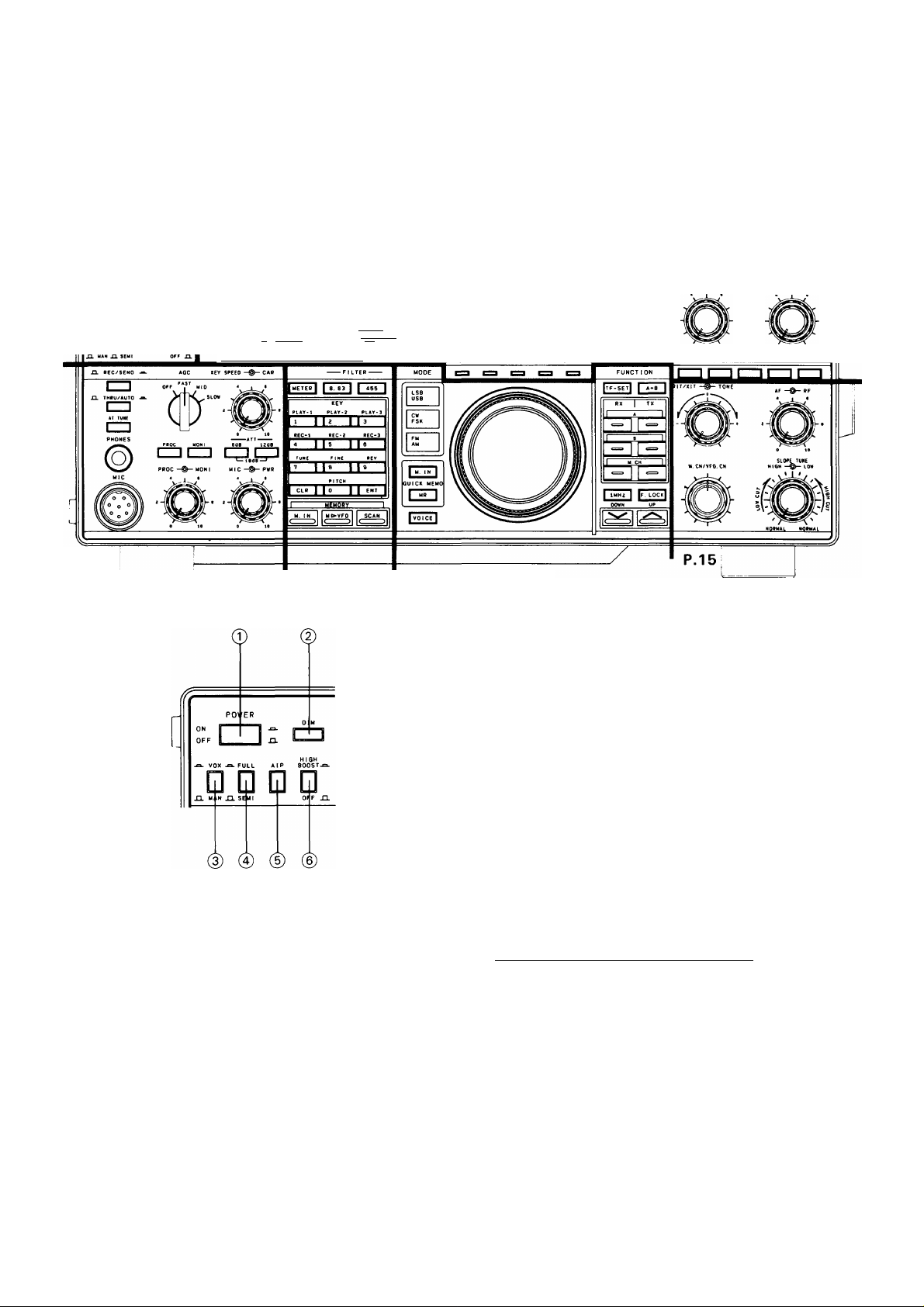
© POWER switch
Press to turn the power ON or OFF.
@ DIM (Dimmer) switch
Selects the intensity of both the digital display and
the meter illumination, bright or dim.
©VOX/MAN switch
VOX (Voice Operated Switch) operation is possible
in SSB, AM or FM operations. Break-in operation is
possible in CW operation. To activate the VOX
circuitry place the VOX switch ON(a).
0FULL/SEMI (Break-in) switch
This switch affects the transmit/receive recovery
time. In the SEMI position the transceiver will key
when the key is depressed and remain in the
transmit position until a preset delay has been
reached. In the FULL position the transceiver will
return to receive as soon as the key is released,
thus allowing you to copy incoming signals between
characters.
® AlP (Advanced Intercept Point) switch
Use AlP when good signal reception can not be
obtained. When switched on, it reduces interference
from strong signals.
When the frequency falls below 9.5 MHz,
initialization takes place automatically.
____________
Note
When AlP is on, the sensitivity of the receiver is
reduced about 10 dB.
©HIGH BOOST switch
The high-frequencies of the transmit audio signal are
emphasized. Intelligibility may be improved,
depending on the characteristics of the microphone
and atmospheric conditions.
10
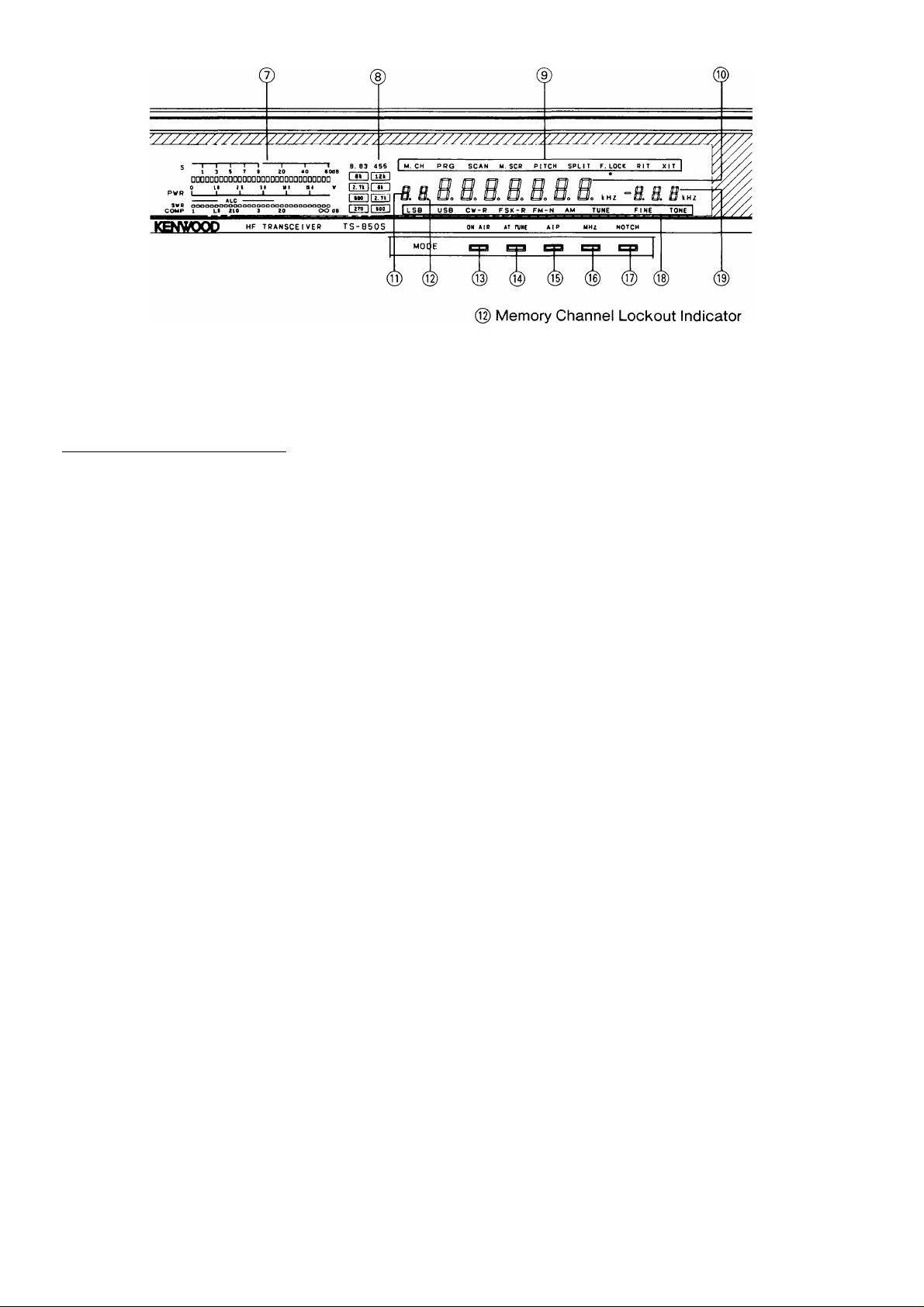
@ Meter
During receive the meter is used as an S-meter.
During transmit the meter is used as a POWER
meter, and is controlled by the METER key, and
provides either VSWR, COMP level or ALC level
readings.
The meter can be used as a peak hold meter.
Please refer to Section 4-10-15.)
________________
Note
One or two segments of the S meter may light
when there is no signal, due to atmospheric noise.
The • display indicates the Memory Channel
currently in the display will be skipped during
Memory Channel scan.
(§)ON AIR indicator
Lights during transmit.
(@ AT TUNE (Antenna Tuner) indicator
Lights to show that the automatic antenna tuner is in
operation. Do not attempt to operate further until it
goes off.
(8) Filter indicators
Indicates which filters have been selected.
(9) M.CH (Memory channel) display
Turns ON during a Memory Channel operation.
PRO (Program) display
Lights during selection or operation on memory
channels 90 to 99.
SCAN display
Turns ON during scanning.
M.SCR (Memory scroll) display
Lights when the M.IN key is pressed. When the
memory scroll function is active you can review
the contents of the memory channels without a
loss of the incoming receive frequency.
PITCH display
Lights when the PITCH function is ON.
SPLIT display
Turns ON during split operation.
F.LOCK display
Lights when the F.LOCK key is ON.
RIT display
Turns ON when using RIT.
XIT display
Turns ON when using XIT.
(10) Frequency display
Indicates the operating frequency. The 10 Hz digit
may be suppressed. (Please refer to Section 4-10-
15.)
(i])Memory Channel number display
Memory Channel Number is displayed.
(g) AIP(Advanced Intercept Point) indicator
Lights when the AlP switch is ON.
(@MHz indicator
Lights when the 1 MHz key is ON.
(17) NOTCH indicator
Lights when the NOTCH switch is ON.
(i|) LSB indicator
Indicates the LSB has been selected.
USB indicator
Indicates the USB has been selected.
CW indicator
Indicates the CW has been selected.
CW-R indicator
Indicates the CW-R(Reverse) has been selected.
FSK indicator
Indicates the FSK has been selected.
FSK-R indicator
Indicates the FSK-R(Reverse) has been
selected.
FM indicator
Indicates the FM has been selected.
FM-N indicator
Indicates the FM-N(narrow) has been selected.
AM indicator
Indicates the AM has been selected.
TUNE indicator
Indicates the TUNE has been selected.
FINE indicator
Indicates the FINE tuning has been selected.
TONE indicator
Indicates the TONE function has been selected.
11
(i|) RIT/XIT frequency display
Shows the amount of RIT/XIT offset to the nearest
10 Hz. Minus “ —” appears in the display when the
RIT / XIT offset is below the transmit / receive
frequency.
Shows the scan speed during scanning.
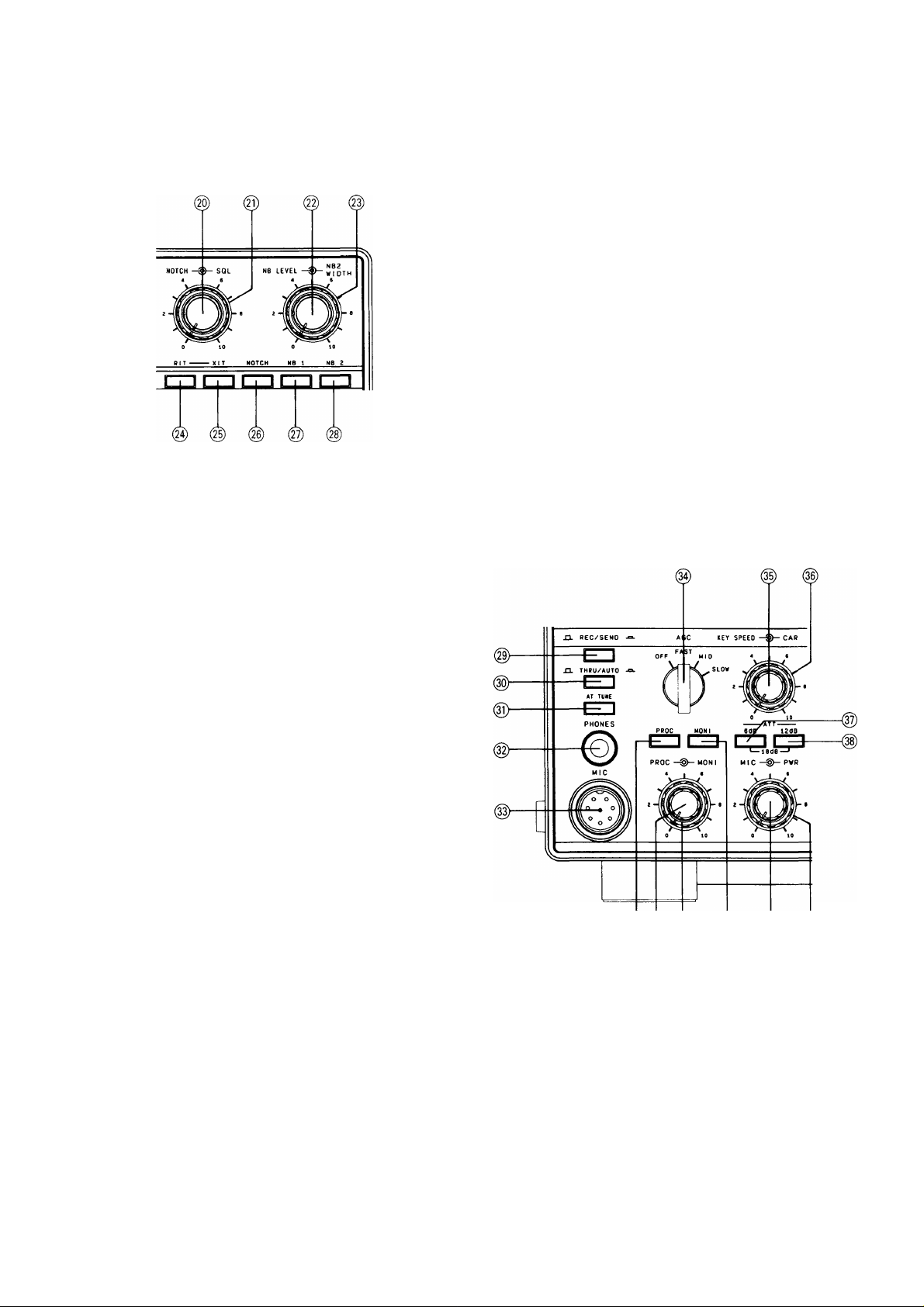
@ NOTCH control
The NOTCH function is used to reduce or eliminate
heterodyne, or CW type signals. The NOTCH filter
will not be effective against SSB, AM or FM type
signals.
Note
This switch is disabled during FM operation.
@NB 1 switch
For pulse type noise, such as generated by
automotive ignition systems, turn the NB 1 switch
ON.
This switch will not help to eliminate atmospheric or
line noises, only pulse type noise.
(^ NB 2 switch
Noise blanker 2 is used for long duration pulse
noise, like the “woodpecker”. To reduce
“woodpecker” radar noise interference, set switch
NB 2 to the ON position (NB 2’s effectiveness
depends on the specific type of interference). If you
use NB 2 for short duration pulse noise, the receive
signal may become distorted, making it difficult to
hear.
Unfortunately no noise blanker can remove all
different types of interference; but the two noise
blankers that have been provided in the TS-850 are
effective in most cases.
If there is no “woodpecker” present, the switch
should be in the OFF position.
@ SQL (Squelch) control
This control is used to eliminate atmospheric noise,
and receiver static noise during no signal periods.
Slowly rotate the control clockwise to the point
where the ambient noise just disappears, and the
speaker shuts off. This point is known as the
squelch threshold point. Now you will only hear
output from the speaker when an incoming signal is
present. For weak signal reception this control
should be fully counterclockwise.
@ NB LEVEL control
Controls the noise blanker operating level.
Use only the minimum level necessary.
(§) NB2 WIDTH control
This control varies the width of the blanking pulse of
NB2.
Notes
1. The NB2 control only works on woodpecker
type noise.
2. If the control is turned too far, the received
signal may be distorted. Set the control for the
best receive signal.
(24) RIT switch
Press to turn the RIT ON or OFF.
@XIT switch
Press to turn the XIT ON or OFF.
® @ ® 0
(§) REC/SEND switch
This switch is used when you want to manually
control transmit or receive.
REC : Places the transceiver into receive.
SEND : Places the transceiver into transmit.
(§)THRU/AUTO switch
THRU : The auto antenna tuner is not used in
transmit.
AUTO: The auto antenna tuner is used in transmit.
(§) NOTCH switch
When this switch is ON, the notch filter is activated.
12
0 AT TUNE switch
When this switch is tuned ON and the THRU/AUTO
switch is placed in the AUTO position, the automatic
tuner will be engaged and the tuner will try to match
the antenna.
©PHONES jack
Output terminal for headphones.
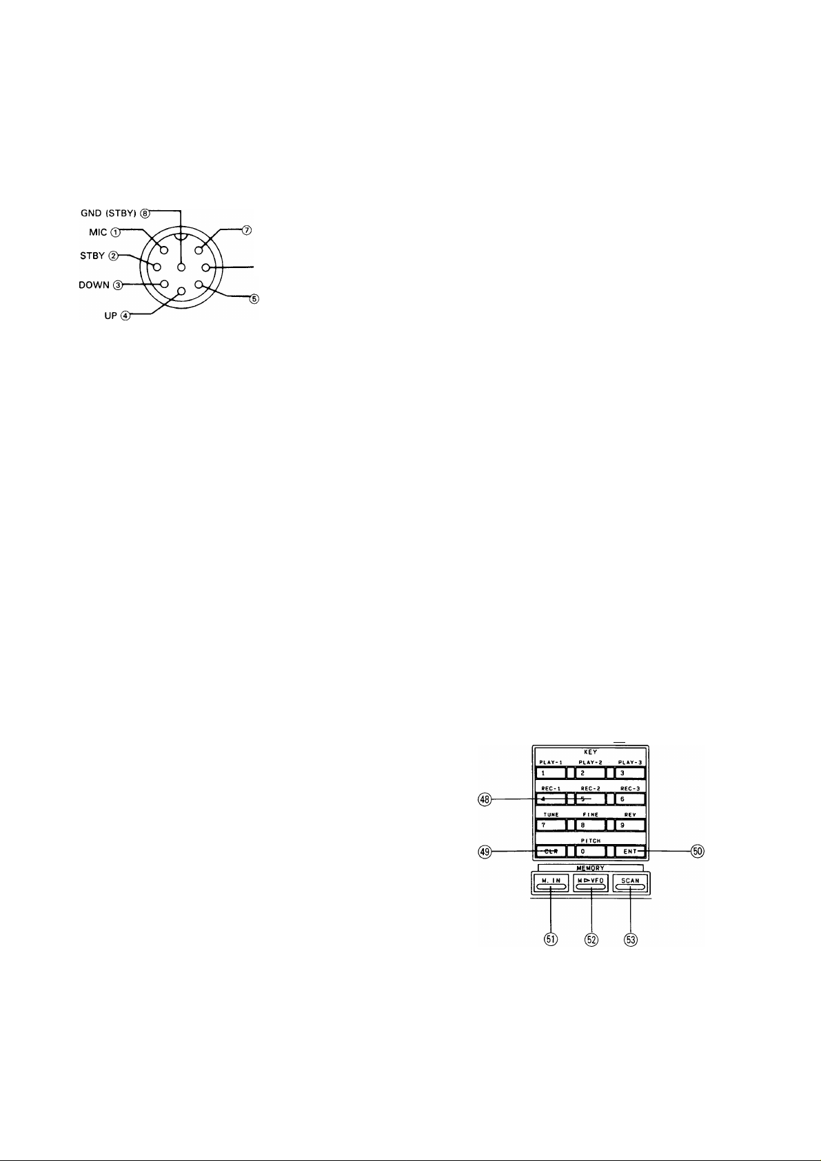
©MIC jack
Microphone connection.
GND (MIC)
<D NC
© PROC (Processor) switch
Effective transmit power output will increase when
the PROC switch is turned ON during SSB mode
operations.
© PROC (Processor) control
Adjust the PROC control while speaking into the
microphone in a normal tone of voice, for a peak
COMP scale reading of no more than 10 dB. Do not
overdrive the COMPRESSOR.
Over driving the compressor will deteriorate voice
quality, increase transmitter noise level, and in
general make copying your signal more difficult.
8 V/approx. 10 mA
MIC connector (Front view)
©AGO switch
This switch selects the operating time constant of
the AGO (Automatic Gain Control) circuit. When the
AGC switch is set to SLOW, the receiver gain and
S-meter readings will react slowly to large input
changes, and when set to FAST, the receiver gain
and S-meter will react quickly to changes in the
input signal level.
The normal position when using all modes is the
SLOW position. When working any of the following
you might wish to use the FAST position.
• When tuning rapidly, use the FAST position.
• When receiving weak signals.
• When a high-speed CW signal is being received.
Note
This switch is disabled during FM operation.
© KEY SPEED control
This controls the speed of the electronic keyer. Turn
the knob clockwise to increase speed.
©MONI (Monitor) control
This controls the volume of the transmit monitor.
This control is operational in the SSB and FSK
mode.
® MONI (Monitor) switch
Allows monitoring of your transmit signal.
This control is operational in the SSB and FSK
mode.
® MIC gain control
Microphone gain can be adjusted during SSB and
AM operations. Gain is increased by turning the
control clockwise.
(© PWR (Power) control
Power can be controlled in all modes. Power is
increased by turning the control clockwise.
Keep the transmit power within the output power
limits of your license.
© ®
©CAR (Carrier level) control
Used to adjust carrier level during CW, AM and FSK.
©6dB ATT (Attenuator) switch
The incoming receive signal level is attenuated by
approximately 6 dB when this switch is activated.
©12dB ATT (Attenuator) switch
The incoming receive signal level is attenuated by
approximately 12 dB when this switch is activated.
The incoming receive signal level is attenuated by
approximately 18 dB when both the 6 dB switch and
12 dB switch are activated.
This control is also useful when a strong signal is
near your desired signal; while some loss will occur
to the desired signal, as well as the undesired signal,
the use of the attenuator will sometimes allow you to
understand what is being received. For normal
receiver performance, this switch should be in the
OFF position.
METER I I 8. ^3
I I
® METER key
The meter function can be changed as follows
during transmission.
13
r*“ SWR---------► ALC
------
► COMP
(The PROC switch
is ON when
the SSB mode.)
■No in(dicator<-
SWR : Indicates voltage standing wave ratio
(VSWR).
ALC : Indicates internal ALC voltage, or the ALC
voltage fed back from a linear amplifier
connected to this transceiver.
COMP: Indicates compression level during speech
processor operations. Do not exceed 10 dB
of compression. The PROC switch is ON
when the SSB mode.
(§)8.83 FILTER key
Selects the desired 8.83MHz filter regardless of
mode.
@455 FILTER key
Selects the desired 455kHz filter regardless of
mode.
@ Numeric keypad
Consists of a series of switches which will be used
to set, turn on and/or turn off functions.
When used in conjunction with the ENT key, the
keypad is used to directly enter a frequency.
When used in conjunction with the M.IN key, the
keypad is used to enter data into a memory channel.
PLAY, REC key
Used to record and play voice or CW messages
for transmission. (The optional DRU-2 digital
recording unit is required.)
TUNE key
Sets the transmit power to half the rated power
regardless of the position of the PWR control.
Outputs a zero beat in CW receive mode. This
key is useful when tuning a linear amplifier.
FINE key
Makes one turn of the tuning knob equal 1 kHz (1
Hz step) to facilitate precise tuning. When the key
is pressed again, normal tuning returns.
REV key
The BFO uses USB for normal CW reception.
With this key, reception becomes possible on
LSB. The BFO uses LSB for normal FSK
operation. With this key, reception becomes
possible on USB. By pressing this key, reverse
shift is also used for transmission.
PITCH key
Press to turn the PITCH function ON or OFF.
@ CLR (Clear) key
Used when reentering memory channel data, erasing
a memory channel, clearing scan, or when
specifying the channels that will be skipped during
scan operations.
@ M.IN key
Used to enter data into a memory channel.
@M^VFO key
Used to transfer
a frequency from memory to the
VFO.
(§)SCAN key
Pressing during VFO operation will initiate program
scan, and pressing during memory operation will
initiate memory scan.
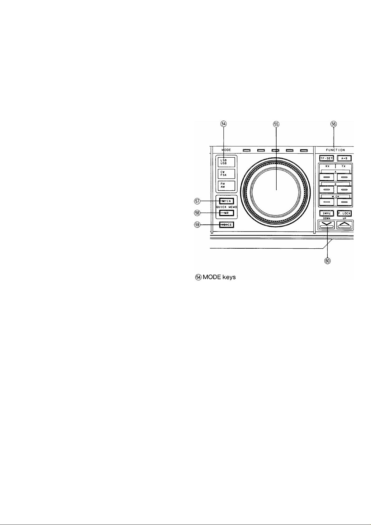
These keys are used to select the desired mode of
operation. When a MODE key is pressed the first
character of that mode will be sounded in Morse
code thru the internal speaker.
LSB/USB key
Press the LSB/USB key to alternate between LSB
and USB mode.
CW/FSK key
Press the CW/FSK key to alternate between CW
(R) and FSK(R) mode.
FM/AM key
Press the FM/AM key to alternate between FM(N)
and AM mode.
(§) TUNING knob (VFO)
Rotate the knob to select the desired frequency.
Fast tuning is possible by rotating the knob rapidly.
The dial drag is adjustable by holding the outside
knob and turning the inside knob clockwise to
increase drag, and counterclockwise to decrease
drag.
(50) ENT (Enter) key
Used to directly enter a frequency from the numeric
keypad.
14
TF-SET key
Depressing this key will allow you to rapidly set
or check the transmit frequency, during SPLIT
operations, without the need of actually
transmitting.
A = B key
Equalizes the frequencies, modes and filter
selection of VFO A and VFO B.
A (VFO A) key
RX ; Press this key to receive signals on VFO A.
TX : Press this key to transmit signals on VFO A.
B (VFO B) key
RX ; Press this key to receive signals on VFO B.
TX : Press this key to transmit signals on VFO B.
M.CH (Memory Channel) key
RX: Press this key to receive signals on the
memory channel.
TX: Press this key to transmit signals on the
memory channel.
Note
When just an RX key (VFO A, VFO B, or M.CH.) is
pressed, the same VFO or memory channel is
used for both reception and transmission. For split
operation, select VFO A or VFO B for reception,
and, for transmission, either select the other VFO
or select TX M.CH.
1MHz key
This key is used to determine if the UP/DOWN
switches will function in 1 MHz steps or only
thru the amateur bands. When the 1 MHz step
position is selected, the MHz indicator will light.
F.LOCK key
The selected dial frequency and mode are
locked.
_________________________________
Note
When the F.LOCK key is on the TF-SET,
FILTER, METER, VOICE keys, AlP, RIT, XIT
switches and RIT/XIT control are still active.
(g)QUICK MEMO M.IN key
This key writes data to the quick memory.
(§) VOICE key
Press this key to activate the optional voice
synthesizer unit VS-2.
(§) UP/DOWN switch
Pressing the UP switch increases the frequency,
and pressing the DOWN switch decreases it.
When the function setting at power on is on, this
switch changes the setting.
RlT/XIT —TONE
(g) RIT/XIT control
RIT (Receiver Incremental Tuning)
The RIT control allows shifting the receiver
frequency. Use of the RIT control will not affect
the transmit frequency.
When the RIT switch is ON, the RIT indicator
will light, and the receive frequency can be
adjusted by using the RIT control.
Note
When the RIT is ON the transmit frequency
may be different from the receive frequency.
For normal operation leave the RIT switch
OFF. It should be used only when necessary.
The scan speed can be changed during scanning
with the RIT control.
XIT (Transmitter Incremental Tuning)
XIT is very similar to RIT. XIT is only active in
the transmit mode. By using the XIT function it is
possible to offset the transmit frequency without
the normal loss of receiver audio that is
experienced when using the SPLIT function.
The RIT / XIT offset can be preset, without
affecting the actual operating frequency by
turning OFF the RIT/XIT and using the RIT/XIT
display to determine the offset.
This is useful when working a DX station who is
“split” within the XIT range.
The RIT / XIT step size is either 10 Hz or 20 Hz.
Please refer to Section 4-10-15 for information on
how to select the desired step size.
@QUICKMEMOMRkey
This key recalls the quick memory.
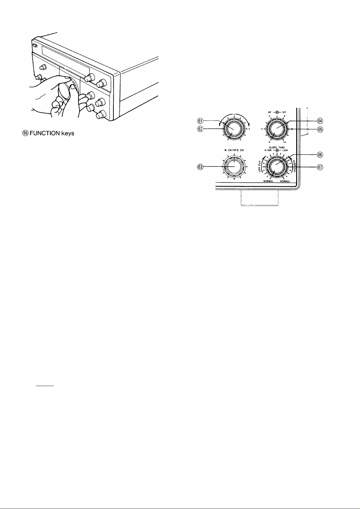
@TONE control
Turn the control to increase or decrease the receiver
audio tone.
15
The standard position is with the control turned fully
clockwise. As the control is turned counterclockwise,
high frequencies are cut.
(§)M.CH/VFO CH control
This control is used to select the desired memory
channel during Memory Channel Operation.
This control is also used to change the frequency in
10 kHz steps during VFO operations.
The control is also used to select the desired power
on function you wish to change. See section 4-10-
15.
(g)AF gain control
Turn the knob to increase or decrease the volume.
Clockwise rotation increases the volume and
counterclockwise rotation decreases the volume.
Note
The output level of the “Beep” and “Sidetone” are
not affected by adjusting of the AF gain control.
(§)RF gain control
This control adjusts the gain of the receiver highfrequency amplifier section.
For normal receiver performance, and maximum
gain, this control should be all the way to the right. If
you are having trouble copying the desired signal
make a note of the stations peak S-meter reading.
Then, adjust the RF gain control left, so that the
meter needle is stationary at this level. Now, all
signals that were less than the desired signal will be
attenuated, such as static noise, etc., making
reception easier.
If the incoming signal pegs the S-meter you can also
reduce the receiver gain by moving the RF gain
control to the left. The S-meter pointer will always
advance up-scale as the RF gain control is moved,
to indicate that the gain has been reduced.
(g) SLOPE TUNE LOW CUT control
Adjust the LOW CUT control clockwise, and
interference from signals lower than the operating
frequency will be reduced. As with the HIGH CUT
control, use of the LOW CUT control will also affect
the audio frequency passband. In this case the low
frequency components of the audio signal will be
reduced.
Note
This control is disabled during FM operation.
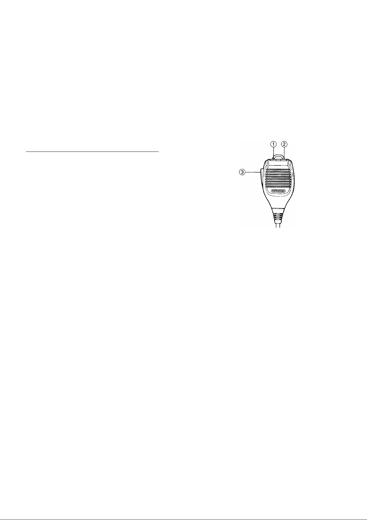
IMicrophone
©(2)UP/DWN(Up/Down) switches
These switches are used to step the VFO frequency
or memory channel up and down. The frequency will
change continuously if the switches are pressed and
held.
(3)PTT (Push To Talk) switch
The transceiver will be placed
whenever this switch is pressed.
into Transmit
Simultaneous use of the RF gain control and AGC
switch
If a strong signal (such as a local station) appears in
the vicinity of the intended receive signal, the S-
meter may show unusual deflection due to the AGC
voltage developed from the strong disturbing signal.
If this occurs, move the RF gain control to the left so
the meter pointer remains at about the original
deflection peak and turn the AGC switch to the
FAST position. This will reduce the unwanted AGC
voltage and permit clear reception.
Note
This control is disabled during FM operation.
(§)SLOPE TUNE HIGH CUT control
Adjust the HIGH CUT control counterclockwise, and
interference from signals higher than the operating
frequency will be reduced. The high-frequency
components of the resulting receiver audio will also
be reduced.
Note
This control is disabled during FM operation.
16
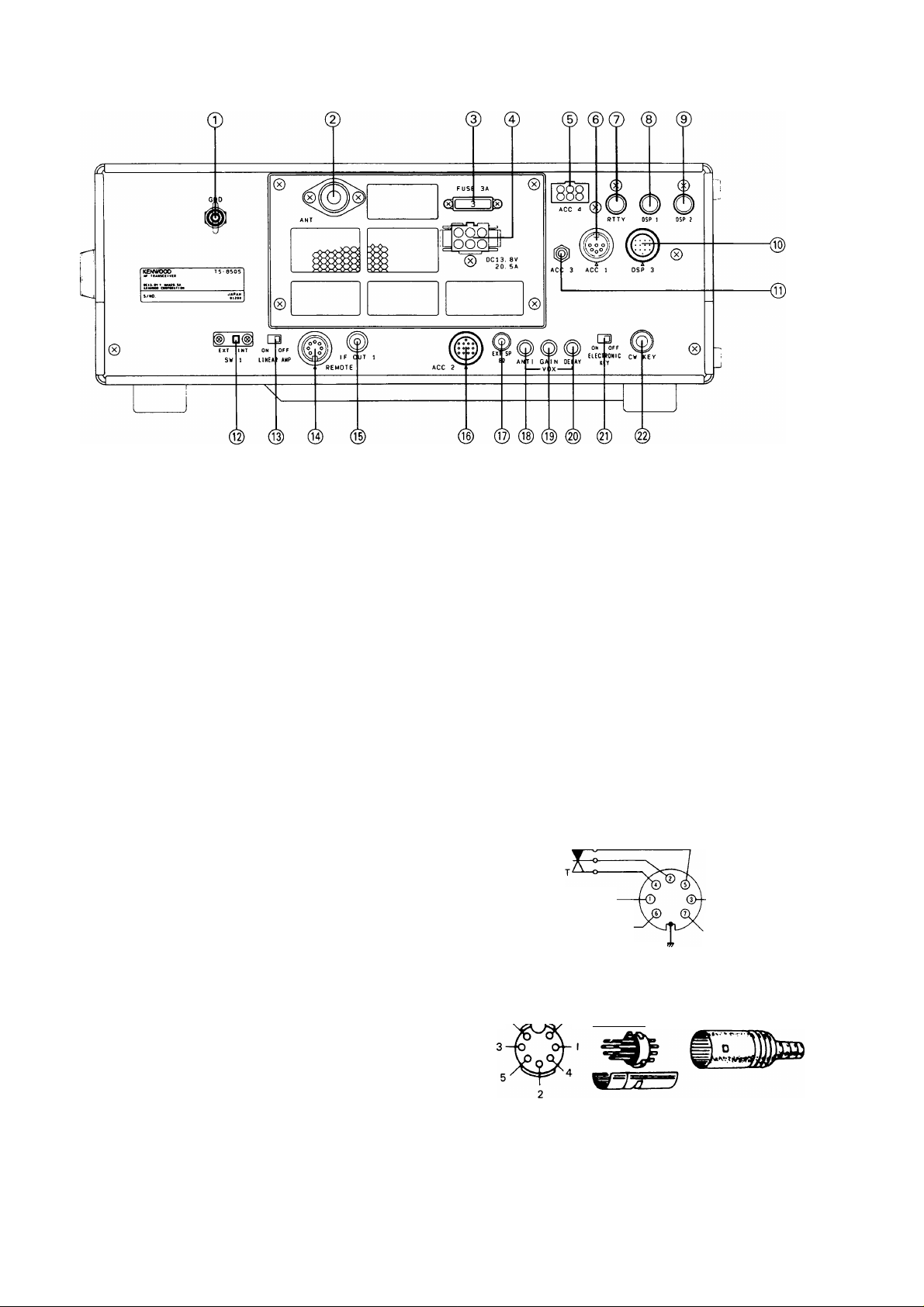
4-1-2. Rear Panel
©GND (Ground) terminal
To prevent electric shock, as well as RFI and BCl,
connect the transceiver to a good earth ground.
(D ANT (Antenna) connector
This connector should be attached to a suitable
antenna for transmitting and receiving. The antenna
cable should be 50-ohm coax, terminated with a PL259 connector.
©FUSE
Power fuse for the ACC 4 connector.
@ DC power connector
This is used to connect the DC power supply.
© ACC 4 connector
The optional AT-300 may be connected here.
©ACC 1 connector
The optional DSP-100 or the optional IF-232C is
connected here.
© RTTY terminal
For connection to an RTTY interface unit, (direct
FSK keying) The terminal is equipped the short pin
plug for the factory.
©DSP 1 terminal
The optional DSP-100 is connected here.
©ACC 3 terminal
This is used to connect the remote controller.
® SW1 switch
This transceiver has a cover on the back to protect
against misoperation. To connect the external
antenna tuner to this unit, remove the cover and
slide switch SW1 to EXT. The built-in antenna tuner
will then not operate.
© LINEAR AMP switch
Activates the internal keying relay for linear amplifier
control.
© REMOTE connector
This connector is used when a linear amplifier is
used.
Control relay p
Speaker output
ALC input
GND'
From standby switch
(PTT circuit for foot switch)
+ 12 VDC ON transmit
max. 10 mA
Internal wiring
View from cord
7. ^ 6
aaa—w-
® DSP 2 terminal
The optional DSP-100 is connected here.
(© DSP 3 connector
The optional DSP-100 is connected here.
© IF OUT 1 terminal
This terminal is for the band scope of the station
monitor.
IF 1 is for connection to the SM-230 for Pan Display.
(8.83 MHz)
17

0|) ACC 2 connector
Terminal numbers and their applications are as
follows :
ACC2 pin assignments
Pin number
Symbol
Use
© © ©©'^
0©0
.0 0©©;
13-pin DIN plug (E07-1351-05)
ACC2 pin assignments
Pin number
1 NO
2
3
4
Symbol Use
NO
ANO
GND Grounding (The shielded wire
©
View from the
©
nrmrrmwy.
No connection
No connection
The receiver audio at a fixed
level independent of AF gain
control setting. Output
voltage : 300 mV / 4.7ki2 or
more at high input level
of the audio output terminal
is connected here.)
rear panel.
11
12
13 SS Standby terminal.
® EXT SP (External speaker) jack
This jack is for connection of an external speaker.
® ANTI control
VOX operations are sometimes difficult with high
speaker volume control settings. The ANTI control is
used to reduce the tendency of the VOX to activate
from inputs from the speaker. The ANTI control is
not active when headphones are connected.
(19) GAIN control
This control adjusts the sensitivity of VOX amplifier.
Adjust this control for your personal preference.
(§) DELAY control
This control adjusts how long the transceiver will
remain keyed after voice input has stopped.
PKD
GND
This is the MIC (microphone)
input pin from the terminal
unit. The input level is
approximately 20 mV.
Grounding (The shielded wire
of the audio output terminal
is connected here.)
Grounding transmits.
5
6
7
8
9
PSQ
Output
voltage
pin for
S-meter.
NO No connection
GND
PKS
This pin is used for
connecting a TNG (Terminal
Node Controller) for use with
packet radio. It is the
Squelch Control terminal and
will not allow packet
communications while
squelch is off.
Output voltage varies with Smeter indication.
Grounding
This is the standby pin used
exclusively for the terminal
unit. When this pin is in use
for standby, the microphone
input is automatically shut off
and the transmit is
operational.
(g) ELECTRONIC KEY switch
Turns the electronic keyer on or off. Turn the switch
off when CW is initiated by a straight key or when
using an external electronic keyer.
@ CW KEY jack
Using shielded line, connect a 6.0mm diameter
phone plug to this jack for CW operation. Connect a
paddle type key to the key jack use a 6.0mm
diameter stereo plug. Open-terminal voltage is
approximately 5 VDC. (See Section 4-4 for additional
key information.)
18
10
NO
No connection
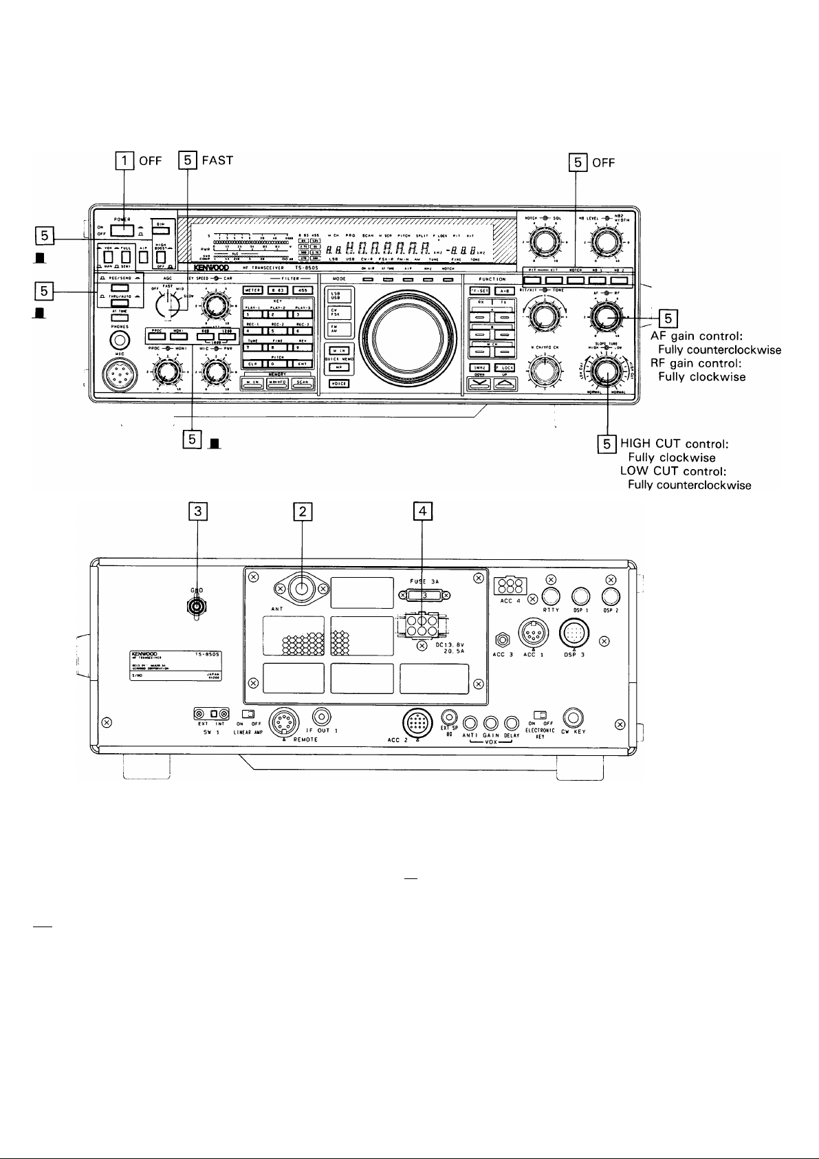
4-2. INITIAL SETTING
Prior to operation ensure the following switches and
controls are set as indicated in the figure below:
pT| Ensure the POWER switch is OFF.
[Y] An antenna must be connected.
Caution
Never transmit without the antenna connected.
3 A ground must be connected.
[4] The DC power cable is connected.
Ensure the front panel controls and switches are
set as shown in the figures above.
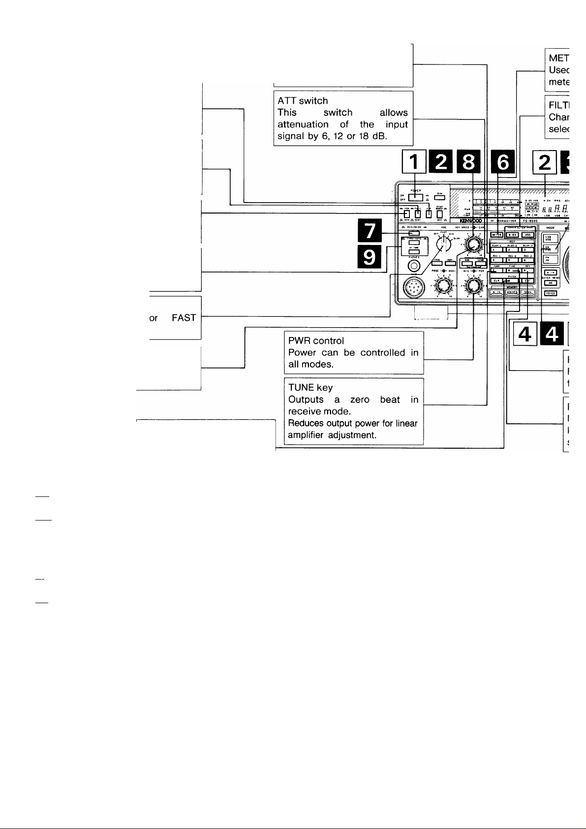
4-3. SSB OPERATION
ATT switch
This switch allows attenuation of the
input signal by 6, 12 or 18 dB.
METER key
Used to select
meter function in
AlP switch
When switched on, it
reduces interference from
strong signals.
VOX/MAN switch
Used to operate VOX.
THRU/AUTO switch
THRU: Antenna tuner is off.
AUTO: Antenna tuner is on.
AGO switch
Set to SLOW.
PROC switch/control
Used to actuate the speech
processor circuit.
PWR control
Power can be controlled in
all modes.
HIGH BOOST switch
The high-frequencies of the transmit
audio signal are emphasized.
MONI switch/control
Allows monitoring of your
transmit signal.
MIC gain control
Microphone gain can be
adjusted during operation.
FILTER key
Changes the
selectivity.
(RECEIVING)
pT| Turn on the DC power supply and then turn the transceiver’s power switch ON.
|~2] A frequency is shown in the display.
3~| Press the UP/DOWN switches to select the desired frequency band.
When the 1 MHz step position is selected, the MHz indicator will light.
[~4~| Select USB or LSB with the MODE key.
The automatic switchover point on the transceiver is 9.5 MHz.
Turn the AF gain control clockwise until a signal or noise is heard.
Q Rotate the TUNING knob and select an open channel.
20
the desired
transmit.
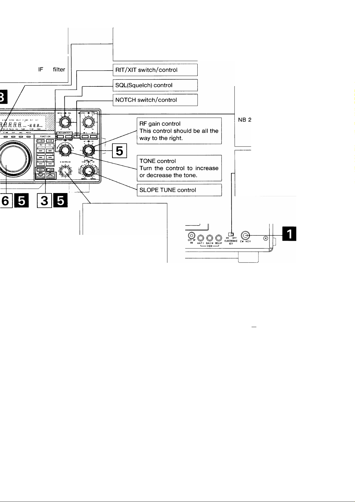
MODE key
Press the LSB/USB key to
alternate between LSB and
USB.
RIT/XIT switch/control
SQL(Squelch) control
FINE key
Makes one turn of the tuning
knob equal 1 kHz (1 Hz
step) to facilitate tuning.
TUNE key
Reduces output power for
linear amplifier adjustment.
NOTCH switch/control
RF gain control
This control should be all the
way to the right.
TONE control
Turn the control to increase
or decrease the tone.
SLOPE TUNE control
M.CH/VFO CH control
This control is also used to
select the desired memory
channel during Memory
Channel Operation.
This control is used to
change the frequency in 10
kHz steps during VFO
operations.
NB switch/control
NB 1 : For pulse type noise,
such as generated by au
tomotive ignition systems.
NB 2 : Noise blanker 2 is used
for long duration pulse
noise, like the “wood
pecker”.
(TRANSMISSION)
D Connect a microphone to the MIC jack.
Q Turn on the DC power supply and then turn the transceiver’s power switch ON.
Q A frequency is shown in the display.
Qj Select USB or LSB with the MODE key.
The automatic switchover point on the transceiver is 9.5 MHz.
Q Enter the desired frequency.
Before transmitting check the frequency for activity so that you do not interrupt another QSO.
Q Press the METER key until the ALC meter lights.
Q Press the microphone PTT switch, or set the REC/SEND switch to SEND.
Q Speak into the microphone and adjust the MIC gain control so that the meter deflection does not exceed the ALC
zone on voice peaks.
Note
Speak into the microphone, holding the microphone
about 5 cm away from your mouth. Close talking or
talking too loudly may reduce transmission clarity or
spread the side bands too much.
—I I I I I
------------
1 3 S T 9 20 40 «006
QOODDQGDDOaOQQDQOOQDOOOOOOOOOO
0 II £1 II Ul 111 V
■ t 1 1 I 1
$WR ooooooaoaooooooQoooooooooooooo
1.1 210
)f- ALC zone -?|
1—T
------
r

4-3-1. SSB AUTO mode shift
This transceiver automatically selects the appropriate sideband when in the SSB mode.
30kHz 9.5MHz 30MHz
LSB
Notes
1. USB is selected for 9.5 MHz and above.
2. The AUTO mode selection will not function when using RIT.
USB
4-3-2. Speech Processor
The Speech Processor is used when signals from your station are weak at the distant station.
During SSB operation (especially DX operations), it may be desirable to increase the relative “talk-power” of the
transmitter by using the speech processor circuitry. This may make the difference between a marginal, and a
copyable signal.
•Operation
Turn the PROC switch ON and place the METER switch to COMP. Adjust the PROC control while speaking
into the microphone in a normal tone of voice, for a peak COMP scale reading of no more than 10 dB. Do not
overdrive the COMPRESSOR. This will deteriorate voice quality, increase transmitter noise level, and in
general make copying your signal more difficult.
Next, set the METER switch to ALC and adjust the MIC gain control while speaking into the microphone.
Ensure that the meter deflection is within the ALC zone!
4-4. CW OPERATION
AlP switch
When switched on, it
reduces interference from
strong signals.
FULL/SEMI switch
During CW operation, selects
either Full Break-in (FULL) or
Semi Break-in (SEMI).
VOX/MAN switch
Used to select Break-in
operation.
THRU/AUTO switch
THRU; Antenna tuner is off.
AUTO: Antenna tuner is on.
AGC switch
Set to MID
normally.
PLAY, REC keys
Records and plays CW
messages for transmission.
KEY SPEED control
This control the speed of the
electronic keyer.
PITCH key
Select the CW receive tone
(RECEIVING)
pT| Turn on the DC power supply and then turn the transceiver’s power switch ON.
|~2] A frequency is shown in the display.
Press the UP/DOWN switches to select the desired frequency band.
When the 1 MHz step position is selected, the MHz indicator will light.
[4] Select CW with the MODE key.
[~^ Turn the AF gain control clockwise until a signal or noise is heard.
Rotate the TUNING knob and select an open channel.
(Tl
i
i
E
E
E
E
22
E
E
E
ER key
to select the desired
r function in transmit.
ER key
ges the
tivity.
MODE key
Press the CW / FSK key to
alternate between CW and
FSK.
NB switch/control
NB 1 : For pulse type noise,
such as generated by au
tomotive ignition systems.
Noise blanker 2 is used
for long duration pulse
noise, like the “wood
pecker”.
ELECTRONIC KEY switch
Turns the electronic keyer on or
off. Turn the switch off when
CW is initiated by a straight key
or when using an external elec
tronic keyer.
M.CH/VFO CH control
iEV key
Reverses the BFO frequency
rom USB to LSB.
This control is used to
change the frequency in 10
kHz steps during VFO
operations.
HNE key
4akes one turn of the tuning
nob equal 1 kHz (1 Hz
tep) to facilitate tuning.
This control is also used to
select the desired memory
channel during Memory
Channel Operation.
^ANSMISSION)
I Connect a key or electronic keyer to the rear panel CW KEY jack.
I Turn on the DC power supply and then turn the transceiver’s power
switch ON. Place the VOX/MAN switch to the VOX position.
I A frequency is shown in the display.
I Select CW with the MODE key.
I Enter the desired frequency.
Before transmitting check the frequency for activity so that you do
not interrupt another QSO.
I Press the METER key until the ALC meter lights.
To use external straight key.
■
Ground Not used
+ 5 V. Contact
Current about 1 mA
+ 5 V, Contact
Current about 1 mA
I Press the key; the ON AIR indicator lights and the meter pointer
deflects.
I Adjust the CAR control until the meter deflection is within the ALC
zone.
OOODQaDQOOQOQaoaaOOQQDODaaODDD
SWR OOOOOOOOOQOO
ALC zone
I Release the key. Receive will be restored and the ON AIR indicator
will turn off.
Electronic keyer connection.
lil
D D
DASH DOT
( )
IIO
Ground
+ 5V
Contact Current
about 1 mA
4-4-1. CW zero-beat Operation
In CW operation equalizing the receiving frequency
with that of your transmit is called “Zero beating”.
The TS-850 enable you to zero beat in the following
manner.
You can forceable change the ratio to you own
personal preference or you can select AUTO
WEIGHT control where the weighting adjusts for
changes in keyer speed.
• Auto Weight (Initial state) [When the Power on
function selection (Number 21) is ON.]
Press the TUNE key and adjust the tuning knob so
that the signal from the other transceiver is zero
beat, and deactivate the TUNE key. The CW can
then be used with the other transceiver zeroed in.
B.
1. If the VOX/MAN switch is VOX, set it to MAN and
depress the key.
2. A side tone will be heard from the speaker.
3. Adjust the TUNING knob so that the transmit
frequency of the station you are receiving is equal
to the side tone frequency.
Zero beating is now completed.
4-4-2. PITCH function
You can specify the desired pitch of the receive tone
during CW reception.
1. Press the PITCH key during CW receiving.
2. Select the desired pitch with the M.CH/VFO CH
control.
400-450 - 500-550-600-650 - 700
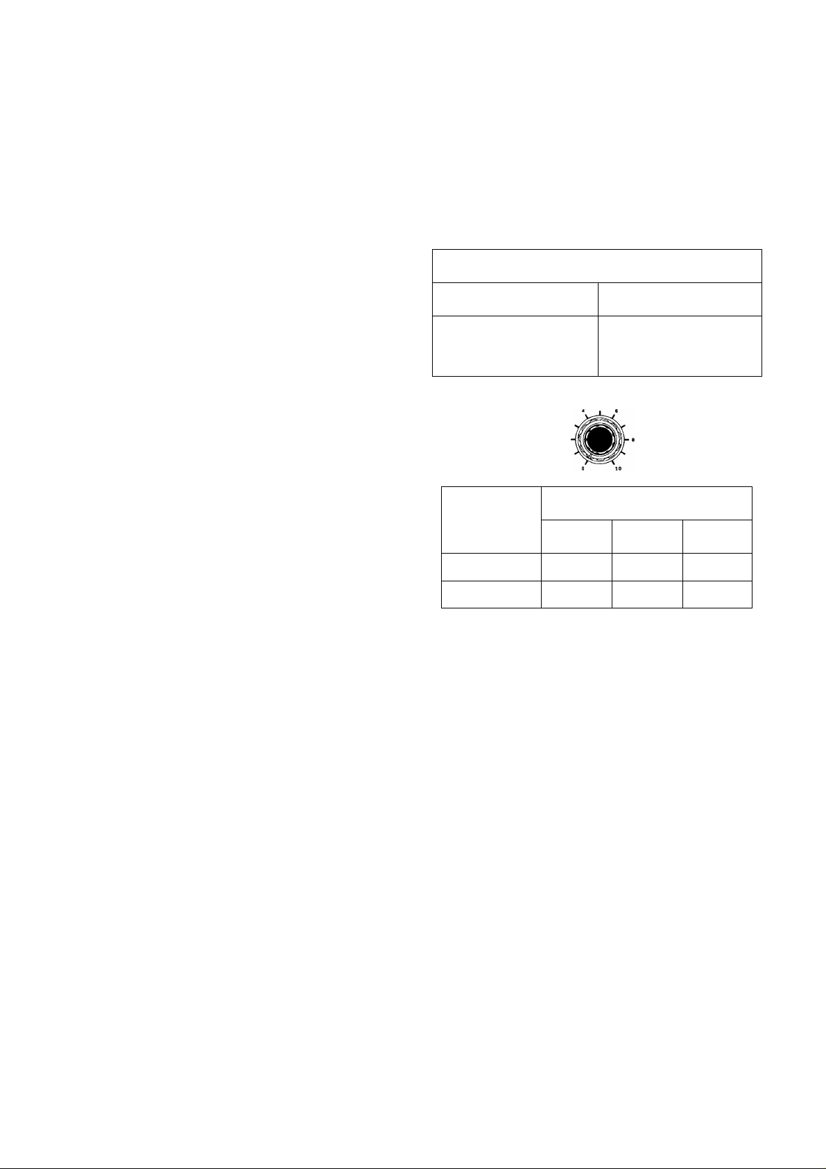
The dot-dash ratio can be set according to the
keying speed. The reverse mode can be turned on
or off with the power on function (menu number 22).
(Please refer to Section 4-10-15.)
Reverse mode
OFF
The faster the keying
speed the longer the
dash.
KEY SPEED —CAR
The faster the keying
speed the shorter the
dash.
ON
KEY SPEED Control Position
Number 22
OFF
ON
0~3 3~7
1 :2.8
1 :3.2
1 :3.0 1 :3.2
1 :3.0
7~10
1 :2.8
1000--950-- 900--850--800^750
(Initial
state)
(Hz)
3. When the PITCH key is pressed again, the pitch
is set, and the normal frequency display returns.
4. The sidetone frequency is the same as the
frequency set for the pitch.
4-4-3. Electronic Keyer Circuit Operation
Place the ELECTRONIC KEY switch on the rear
panel to ON. Connect a paddle type key to the CW
KEY jack use a 6.0 mm diameter stereo plug.
Adjust the KEY SPEED control for the desired
speed.
■Weight Adjustment
The ratio of dot / space / dash can be adjusted as
follows:
DOT SPACE
1 1
The dot-dash ratio has been factory preset to 1 : 3
and will remain so regardless of the keyer speed.
DASH
3
SPACE
1
Notes
1. It requires a little time to change the ratio at
about the 3 and 7 positions of the KEY SPEED
control where some hysteresis occurs.
2. These dot/dash ratios are only approximate.
• Manual Weight [When the Power on function
selection (Number 21) is OFF.]
The dot-dash ratio can be set between 1:2.5 and
1:4.0 with the power on function (menu number 23).
(Please refer to Section 4-10-15.)
For the CW message storing, see Section 4-13.
DRS function.
■SEMI and FULL break-in operation
Two break-in methods are provided with the
transceiver, SEMI and FULL break-in. With either
break-in operation, depressing the CW key will
cause the radio to transmit without the need for
manually switching the REC / SEND switch. The
difference between FULL and SEMI break-in is that
during FULL break-in operation it is possible to listen
between dots and dashes, and that during SEMI
break-in it is not.
23

Note
With either SEMI or FULL break-in operation, cross
band / cross mode operation is not possible.
Additionally, when you are using FULL break-in
you should not work cross band splits, only in the
same band.
This transceiver also provides a sidetone oscillator
circuit to allow monitoring of your CW signal during
transmission.
(a) Semi-automatic break-in
Depressing the CW key will automatically place
the transceiver into the transmit mode. Transmit
mode will be maintained for a period determined
by the setting of the DELAY control on the front
panel of the transceiver, even after the CW key is
released.
(b) Full-automatic break-in
Depressing the CW key will automatically place
the transceiver into the transmit mode. Releasing
the CW key will return the radio to receive
immediately enabling reception between
characters.
■ When the electronic keyer is used as Bug key
When the electronic keyer is used as the Bug key,
turn the function on with the function setting (menu
number 24) at power on. (Please refer to Section 4-
10-15.)
____________________________________
Note
When the ELECTRONIC KEY changeover switch
is on, menu number 24 is displayed.
Cautions
1. The TL-922 / 922A linear amplifier is not
designed for full break-in type operation.
Attempting to use this accessory in the FULL
break-in mode may cause damage to the
linear amplifier.
2. The switching time between transmit and
receive decreases as you increase your
keying speed. This limits the maximum
keying speed that is available during FULL
break-in operation. When using high speed
CW you should use SEMI break-in.
3. During SPLIT operations with FULL break-in,
clicks may be heard in the monitoring tone or
received signal depending on the
combination of the transmit / receive
frequencies.
4. During full break-in, the received audio that
passes through the 250 Hz band CW narrow
filter may click because of its delay time.
5. If the TS-850S is used with CW filter YK88CN-1 (option) or YG-455CN-1 (option), it is
not suitable for full break-in operation
because it has a delay time when the signal
passes through the narrow-band filter. In this
case, you are recommended to perform
SEMI break-in operations.
24
Loading...