


 Loading...
Distinctive Performance
TS-590S
HF/50 MHz ALL MODE TRANSCEIVER

ABOUT THIS MANUAL
This in-depth manual is intended to explain the features of the TS-590S and its convenient use. We hope that this manual, as a general HF transceiver guide will be of your benefit, to whoever reads this manual, whether you have already purchased a TS-590S, are thinking of purchasing of this product, or are interested in HF transceivers.
About Copyright
 Copyright of this Manual and Software
All copyrights and other intellectual property rights for this in-depth manual and relevant technical documents as well as the software described in this in-depth manual and relevant technical documents, and help texts and manuals attached to the software are owned by Kenwood Corporation.
A right to use the software described in this in-depth manual and relevant technical documents, and help texts and manuals attached to the software is granted to a licensee by Kenwood Corporation; however, the title to and ownership for the software shall be owned by Kenwood Corporation. Refer to this in-depth manual and relevant technical documents, and help texts and manuals attached to the software for details.
Kenwood Corporation does not warrant that quality and performance of the software described in this in-depth manual and relevant technical documents, and help texts and manuals attached to the software conform to the applicability of any use, and Kenwood Corporation shall be free from liability for any defects, damage or loss, or from any warranty for anything other than what is expressly described in this in-depth manual and relevant technical documents, and help texts and manuals attached to the software.
Any distribution, resale, lease, waiver, assignment or disclosure on a website of all in-depth manual and relevant technical documents, and help texts and manuals attached to the software written and made by Kenwood Corporation.
 About Trademarks and Intellectual Properties
•Microsoft, Windows®XP, Windows Vista®, Windows®7 and Windows logo are registered trademarks of Microsoft Corporation.
•All other product names referenced herein are trademarks or registered trademarks of their respective manufacturers. ™ and ® are omitted in this manual.
 Other Restrictions
The measured values exampled in this document are examples and do not guarantee the performance of the model.
Cover 2 |
TS-590S |

CONTENTS
1 |
RECEPTION ..................................... |
1 |
|
|
1.1 |
Type of Conversion ............................ |
1 |
|
1.2 |
Down Conversion ............................... |
3 |
|
1.3 |
Up Conversion.................................... |
8 |
|
1.4 |
RX Auxiliary Circuits........................... |
9 |
2 |
TRANSMISSION............................. |
11 |
|
2.1Kenwood Traditional Transmitting
Circuitry ............................................ |
11 |
|
2.1.1 |
IF Circuits ......................................... |
11 |
2.1.2 |
FET Final Circuit............................... |
11 |
2.2High-speed Relay-controlled
|
|
Antenna Tuner.................................. |
13 |
|
2.3 |
REMOTE Connector ........................ |
13 |
|
2.4 |
DRV Terminal................................... |
15 |
3 |
LOCAL OSCILLATOR ................... |
19 |
|
4 |
DSP................................................. |
20 |
|
4.1Multipurpose 32-bit Floating Point
DSP.................................................. |
20 |
4.2Advanced AGC Control via IF Digital
Processing........................................ |
21 |
4.3Interference Elimination Within AGC
Loop ................................................. |
23 |
|
4.3.1 |
Digital IF Filter .................................. |
23 |
4.3.2 |
Types of Digital IF Filters.................. |
24 |
4.3.3Manual Notch Filter and Auto Notch
|
Filter.................................................. |
25 |
4.3.4 Digital Noise Blanker (NB2).............. |
26 |
|
4.4 |
Demodulation ................................... |
27 |
4.5 |
Modulation........................................ |
28 |
4.6 DSP-based Auxiliary Circuits |
|
(for RX)............................................. |
29 |
4.6.1 Beat Cancel (AF Processing) ........... |
29 |
4.6.2Noise Blanker NB2
|
(IF Processing) ................................. |
30 |
4.6.3 |
Overview of Noise Reduction ........... |
31 |
4.6.4NR1 (Spectral Subtraction Method)
(AF Processing)................................ |
32 |
4.6.5NR1 (Based on a Line Enhancer)
|
(AF Processing)................................ |
34 |
4.6.6 |
NR2 (AF Processing)........................ |
35 |
4.7DSP-based Auxiliary Circuits
(for TX) ............................................. |
36 |
4.7.1 Speech Processor |
|
(AF Processing) ................................ |
36 |
4.8 DSP-based Auxiliary Circuits |
|
(Common to TX/RX) ........................ |
37 |
4.8.1 TX Equalizer & RX Equalizer |
|
(AF Processing) ................................ |
37 |
5 SOFTWARE: ENHANCING |
|
OPERATING PLEASURE............... |
38 |
5.1Extended Data-mode Related
Functions ......................................... |
38 |
5.2 Drive Out.......................................... |
39 |
5.3Single Button Toggles IF Filters
between A and B.............................. |
40 |
5.4Double Function Keys and Hold Time
Selection .......................................... |
41 |
5.5Mode Selection of Built-in Electronic
Keyer................................................ |
41 |
5.6Switchover of Shift Frequency Interlocked with Change of Pitch
|
Frequency ........................................ |
41 |
5.7 |
Power-on Message .......................... |
41 |
5.8 |
Quick Memory Function ................... |
42 |
5.9 |
Cross Tone Function........................ |
42 |
5.10 |
PF Keys ........................................... |
42 |
5.11 |
Expansion of Voice Guide Function |
|
|
(Optional VGS-1 Required).............. |
44 |
5.12 |
Easy Updating of Firmware.............. |
45 |
6APPEARANCE DESIGN: “DESIGN CONCEPT” REVEALED
|
BY DESIGNING ENGINEER........... |
46 |
|
7 |
STRUCTURAL FEATURES............ |
47 |
|
|
7.1 |
Cooling............................................. |
47 |
|
7.2 |
LCD.................................................. |
50 |
|
7.3 |
Main Control Knob ........................... |
51 |
8 |
EXPANSIVE APPLICATION |
|
|
|
SOFTWARE.................................... |
52 |
|
|
8.1 |
Windows Related Software.............. |
52 |
|
8.2 |
System Configurations..................... |
52 |
8.2.1Controlling TS-590S from a PC using
the COM Connector.......................... |
52 |
TS-590S |
I |

CONTENTS
8.2.2Controlling TS-590S from a PC using
the USB Connector.......................... |
53 |
8.2.3Controlling TS-590S from a PC using the COM and ACC2 connectors
(microphone and speaker connected to |
|
the PC to be used)........................... |
53 |
8.2.4Controlling TS-590S from a PC using the USB connector (microphone and
speaker connected to the PC to be |
|
used)................................................ |
53 |
8.2.5Controlling TS-590S from a PC on a
Remote Site ..................................... |
54 |
8.3New ARCP-590 (Amateur Radio
Control Program for TS-590S) |
|
Freeware .......................................... |
54 |
8.3.1Basic Specifications Inherited from
ARCP-480........................................ |
55 |
8.3.2 User Interfaces ................................ |
55 |
8.3.3KNS (Kenwood Network Command
|
System)............................................ |
56 |
8.3.4 |
Visual Scan...................................... |
58 |
8.3.5 |
Audio Equalizer................................ |
58 |
8.4ARHP-590 (Amateur Radio Host
Program) Freeware .......................... |
59 |
8.4.1Basic Specifications Inherited from
ARHP-10.......................................... |
59 |
8.4.2 User Interfaces ................................ |
59 |
8.4.3KNS (Kenwood Network Command
System)............................................ |
60 |
8.4.4Disabling AF Gain Control from
ARCP-590........................................ |
60 |
8.5New ARUA-10 (USB Audio Controller)
Freeware .......................................... |
60 |
|
8.5.1 |
Basic Functions ............................... |
61 |
8.5.2 |
Operation ......................................... |
61 |
8.5.3 |
Setup ............................................... |
61 |
8.5.4 Starting and Stopping ARUA-10 ...... |
62 |
|
8.5.5 |
Adjusting Volume............................. |
62 |
8.5.6Automatic Execution when Windows
Starts ............................................... |
62 |
8.6New ARVP-10H (Amateur Radio VoIP
Program) Freeware .......................... |
63 |
8.6.1 Basic Functions ............................... |
64 |
8.6.2Setup of ARVP-10H
(Host Station)................................... |
64 |
8.6.3Making ARVP-10H (host station)
Online or Offline............................... |
64 |
8.6.4Setup of ARVP-10R
(remote station)................................ |
65 |
8.6.5Connecting and Disconnecting
ARVP-10R (Remote Station) ........... |
65 |
8.6.6 Adjusting Volume............................. |
65 |
8.7 New Virtual COM Port Driver ........... |
66 |
9 OPTIONAL ACCESSORY ............. |
67 |
9.1PS-60 Regulated DC Power
Supply .............................................. |
67 |
9.2 Rectifier Circuit................................. |
68 |
9.3Switching Circuit, Constant-voltage
Circuit and Protection Circuit............ |
68 |
II |
TS-590S |

PRODUCT PLANNING OBJECTIVES
At the end of September, 2010, the TS-590S, a Kenwood HF band amateur radio transceiver was launched after the 7-year long silence since the releasing of TS-480S.
As implied by this model name, TS-590S is the “legitimate successor to the TS-570S”.
The product category taken over from the TS-570S by the TS-590S was created by combining the line of compact HF transceivers that was initiated by the TS-120S and inherited by TS-450S; and the line of TS-500s represented by the TS-520S that swept the market. The product is designed as a transceiver in a preferable price-to-performance range that has sufficient features and performance for the day-to-day use and that arrives with a compact size that is convenient for operations from a fixed station as well as from a mobile station for use in any fields.
One of the noteworthy planning policies is improvement of fundamental receive performance. To achieve the objective, a new structure has been employed for the front end. However, the performance of a transceiver as a whole is not determined solely by the front end. It is imperative to carefully design, in addition to the DSP and local oscillator, all the other elements including transmit performance and ease of operation in a comprehensive manner.
On the TS-590S, we have also made a drastic modification to the external appearance and we are confident it has a “face” that satisfies all HF users.
Following are the major features of the TS-590S:
Superb receive performance and astounding adjacent dynamic range characteristics
•Adoption of powerful roofing filters of 500 Hz/ 2.7 kHz
(During the reception in CW, FSK and SSB modes in 1.8 MHz, 3.5 MHz, 7 MHz, 21 MHz amateur bands, and if the final passband is 2.7 kHz or less, either of the filters is automatically selected.)
•Superior C/N (carrier-to-noise ratio) thanking to the high-precision DDS (direct digital synthesizer) Substantial reduction of noise caused by unwanted adjacent signals
Adoption of a 32-bit floating point DSP to realize various functions
•Advanced digital AGC control realized with DSP processing of the signal derived from the IF stage
•A wide variety of interference removal functions including newly developed noise reductions, WIDTH/SHIFT and IF notch
High-reliability design that offers stable operation
•Heavy-duty specifications for a rig enduring from continuous operation in a contest and similar occasions
•Built-in automatic antenna tuner
•High frequency stability of ±0.5 ppm thanking to the optional SO-3 TCXO (from -10°C through +50°C or 33.8°F to 122.0°F) (The transceiver frequency is ±5ppm when the SO-3 option is not installed)
Outstanding operational ergonomics, more comfortable transmission and reception
•Easy-to-use menu structure allowing excellent operability
•Large-size display equipped with the selectable LED backlight from 2 colors
•USB port that accepts not only control signals but enables input/output of transmit/receive audio signals from a PC
For details, refer to these pages providing technical explanations.
TS-590S |
CONTENTS |
I |

Development Spirit
TS-590S was planned as the “legitimate successor to the TS-570S” after 14 years or more of time have elapsed since the first market appearance of TS-570S in 1996. TS-590S is titled with the 500s model number with the TS-570S but, needless to say, we started the development as a totally new transceiver.
First, let’s look back on the TS-570S.
The product concepts of the TS-570S were “ease of operation” and “providing basic performance sufficient for rag-chewing and DX operation at a preferable price range”.
Soon after the launch of the TS-570S, the simple exterior appearance with rounded buttons stirred both positive and negative market comments, but we have received many favorable opinions from users who actually used the transceiver, such as “Buttons are easy to press” and “Setup of functions is easy to understand”.
In fact, the TS-570S employed an up-conversion circuitry configuration that was very popular at that time and provided sufficient basic performance in a transceiver having the cost-to-performance-ratio price range. The TS-570S incorporated an AF DSP, which was usually offered as an external device around that time, and received favorable reception as “a younger brother” of TS-870S that was equipped with IF DSP.
The most notable feature of the TS-590S is the superior receive performance that exceeds expectations in its the cost-to-performance-ratio price range. It goes without saying, of course, that we invested as much effort in all the other elements as in the RX circuit in developing the TS-590S.
In evaluating a transceiver, in addition to electrical characteristics represented by numerical data, ease of operation and visibility are also important criteria. As for ease of operation, Kenwood has been developing transceivers on the basis of operability of successive HF transceivers, to which users' voices also have been reflected; therefore, we need to take the history and background into consideration while designing a product.
Though the new TS-590S inherits the DNA of Kenwood’s HF transceivers, new technologies and ideas are also added. We are confident that all users, from the newest user to the most experienced veteran user, will be satisfied with this transceiver.
As for the development objectives and backdrop of the “totally new” portion of the product, we will reveal them in the technical explanations of the chapters subsequently.
Be our guest and allow us to share the development background of the TS-590S and what’s in the spirit of the development engineers.
Kenwood HF Transceiver Development Team
II |
CONTENTS |
TS-590S |

1 RECEPTION
1.1 Type of Conversion
Receive performance is one of the key indicators that is used to evaluate a transceiver. And, above all, the capability to protect against interference from adjacent signals close to the target signal is of the utmost importance.
To attain this goal, a circuit with a good large signal behavior characteristic is used for the first mixer of the RX section. In recent years, a filter used between the mixer and the subsequent stage (roofing filter) is also gaining much attention as a very important component.
About 30 years ago, an up-conversion circuit configuration (where the first IF is higher than the upper limit of RX frequency) appeared as an RX circuit design to provide general coverage receiving from LF through the HF band. This RX system was also adopted by amateur radio transceivers of the time to enable reception of overseas broadcasting and other signals outside amateur bands and, as a result, from that time on, almost all HF transceivers have been equipped with an up-conversion RX section.
The passband of roofing filters used in an up-conversion RX design is typically 15 to 20 kHz. However, in the case an interfering signal is only several kHz away from the target signal, the interfering signal also passes the roofing filter and the target signal is masked first in the subsequent stage. As a result, sometimes the performance of the first mixer was not extended to the best use.
That is the reason a design to switch the pass bandwidth to be 3 kHz, 6 kHz, or 15 kHz is becoming prevalent in recent transceivers. Some products can select a bandwidth as narrow as several hundred Hz and these products are very highly accepted in the market.
Meanwhile, Kenwood’s HF transceivers, which were designed 7 years ago or earlier, adopt roofing filters with a wide passband. Obviously, they still have satisfactory performance outside the pass bandwidth.
Against this backdrop, we started the development of the TS-590S by considering the circuit type that mostly focuses on the characteristics of adjacent interference elimination.
In the early stage of the TS-590S’s product development, considering the product positioning in the market, we also examined the RX design to be able to switch among the roofing filters of 3 kHz, 6 kHz and 15 kHz. However, the bandwidth of 3 kHz is too wide for CW, though it is fairly narrow for an SSB. We wanted to adopt a 500 Hz filter by all means for CW enthusiasts. However, there was a big challenge to be solved.
When it comes to the pass bandwidth of a roofing filter, at a frequency as high as 73 MHz, which is Kenwood’s mainstream first IF frequency, it is difficult to mass-produce filters with bandwidth as narrow as 500 Hz. To solve this problem, there was no other choice but to lower the first IF frequency.
After reviewing, we decided to lower the first IF to 11.374 MHz. This is called a down-conversion design. (If the receive frequency is lower than 11.374 MHz, the operation will be up conversion. However, because the first IF is lower than the highest receive frequency (60 MHz), we call the conversion type “down conversion”.)
Yet, this circuit design has a drawback. When the IF frequency that was once raised 30 years ago to provide general coverage reception is lowered again (to 8.83 MHz that was then used), images and spurious signals are produced (which are relevant not only to reception but to transmission) and these causes must be addressed one by one.
Needless to say, it is technically possible to tackle individual problems but, to do so, many additional circuits and components are required, which may result in a higher product price. In terms of market positioning, TS-590S must be a product in a competitive price range having higher cost-to- performance ratio. After examining various frequency configurations, we have selected a dual-mode conversion frequency configuration for the new TS-590S to satisfy both the performance and price requirements.
TS-590S |
CONTENTS |
1 |
1 RECEPTION
1st 11.374 MHz
500 Hz
2.7 kHz
 Down-conversion path Double superheterodyne
For 1.8/ 3.5/ 7/ 14/ 21 MHz Amateur bands If RX passband is 2.7 kHz or less
When receiving in SSB/ CW/ FSK modes
IF
DSP
1st Mixer 73.095 MHz 2nd Mixer 10.695 MHz |
3rd Mixer |
24 kHz |
 Up-conversion path Triple superheterodyne
For all the conditions (incl. when transmitting) other than listed above for down conversion
(Blocks that are not relevant for the explanation of the conversion type are omitted.)
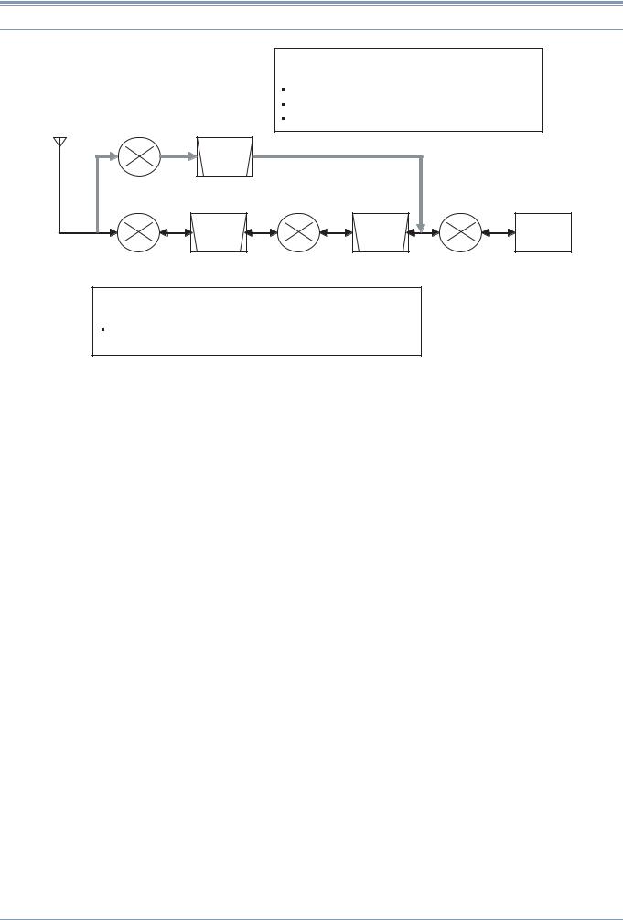
Figure 1-1 Dual-mode Conversion Frequency Configuration
First, let us begin with explanation about the up-conversion path.
In the up-conversion path, double-headed arrows are shown at each stage pointing in both directions. This means a transmit signal as well as a receive signal is processed in the upconversion path. The circuit configuration is a triple-conversion design featuring an IF DSP, a typical configuration for an HF transceiver. (Replacing the IF DSP with an AF DSP and the third Mixer with a modulator and demodulator changes it to be the configuration of TS-480S.)
The pass bandwidth of the filter is about 15 kHz at 73.095 MHz, and at 10.695 MHz, it varies depending on the mode and the RX bandwidth. In CW, SSB and FSK modes, the bandwidth is 2.7 kHz, in AM mode 6 kHz, and in FM mode 15 kHz. (In transmit, the signal passes the 6 kHz filter regardless of the mode. The final bandwidth is determined by the DSP.)
The up-conversion path is applied only in conditions when no down-conversion path is used. Next is the down-conversion path.
In the down-conversion path, only a single-ended arrow is shown at each stage. This means the down-conversion operation is applied only to RX signals.
Also, in the figure the conditions in which the down conversion operates are described. These conditions are designed to cover the bands, modes and bandwidths that are commonly used in a contest and on similar occasions.
On the surface, the circuit configuration may seem too complex and wasteful. Still, due to the frequency configuration that focuses on particular points, the general coverage reception across the continuous frequency range of 30 kHz through 60 MHz covered by the VFO is maintained as on previous models. As a result, we have successfully produced a transceiver in a competitive price range that achieves excellent receive performance comparable to the most high-end HF transceivers on the market.
As for the up-conversion path, though the same frequency configuration is used as in the previous models, the roofing filters have been improved to have better characteristics to protect against interference within the pass bandwidth. For details, refer to 1.3 Up Conversion.
2 |
CONTENTS |
TS-590S |
1 RECEPTION
1.2 Down Conversion
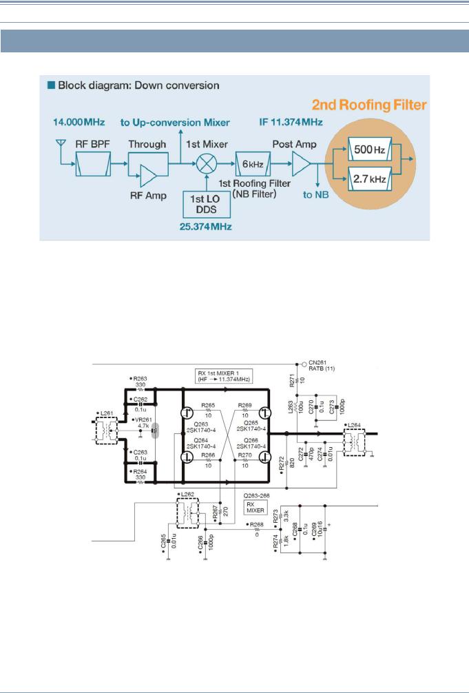
Figure 1-2 Block diagram: Down Conversion
Figure 1-2 describes the circuit configuration around the first mixer of the down-conversion path, showing the relationships between frequencies upon receipt of a 14 MHz signal.
The signal from the antenna passes the RF BPF or LPF (as a receive LPF, it divides the frequency band of 30 kHz to 60 MHz into 12 ranges) and RF Amp (or bypasses it) to be sent into the first mixer. Because in the first mixer section, a different mixer is used for the up conversion and down conversion respectively, the suitable mixer is selected according to the conditions.
Figure 1-3 Receiver Mixer Circuit
TS-590S |
CONTENTS |
3 |
1 RECEPTION
The receiver mixer circuit is a quad mixer consisting of four 2SK1740 JFETs.
The mixer circuit achieves superior characteristics thanks to the revision of I/O port matching and the optimization of biases.
With the signal provided by the first local oscillator, the RX signal is converted to 11.374 MHz (first IF frequency).
The converted RX signal passes the first roofing filter of pass bandwidth 6 kHz and in the subsequent stage the signal is moderately amplified by the post amplifier, and sent into the second roofing filter. Part of the signal is also sent to the noise blanker.
The role of the first roofing filer is to limit the bandwidth for the sake of the noise blanker. We have selected a pass bandwidth of 6 kHz that does not affect pulse noise. Besides, by setting the intercept point of the post amplifier higher than that of the mixer, the deterioration of the two-tone characteristics is minimized within the pass bandwidth.
For second roofing filters, two 6-pole MCFs of 500 Hz and of 2.7 kHz respectively are equipped as standard at the time of purchase of your transceiver. Which filter is used is automatically determined according to the final pass bandwidth, i.e. depending on the conditions including the bandwidth selection made with WIDTH or LO CUT/ HI CUT controls on the front panel.
For example, in CW or FSK mode, if WIDTH is 500 Hz or less, the 500 Hz filter is selected and if WIDTH is 600 Hz or more, 2.7 kHz filter is selected. In SSB mode, if the difference between the HI CUT and LO CUT frequencies is 2.7 kHz or less, the 2.7 kHz filter is selected and if the combination produces exceeds a difference of 2.7 kHz, the up-conversion path is automatically applied. (In SSBDATA mode, if WIDTH is 500 Hz or less, the 500 Hz filter is selected.)
In AM and FM modes, because the pass bandwidth of the down conversion path is too narrow, the signal is received with the up conversion path.
These operations are used in the amateur radio bands of 1.8 MHz, 3.5 MHz, 7 MHz, 14 MHz and 21 MHz, and for other amateur radio bands including WRC bands, and for other frequency ranges of general coverage receiving, up conversion is used regardless of the mode and pass bandwidth. (Since this switchover is determined by the CPU taking various conditions into its criteria, the conversion path cannot manually be selected.)
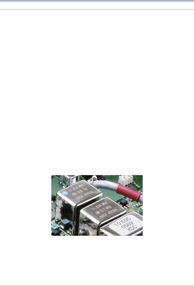
Figure 1-4 MCF
Figure 1-4 is an image of MCFs. From left to right, there is the 500 Hz filter at 11.374 MHz that is used in down conversion and next is the 2.7 kHz filter at 11.374 MHz.
At the rightmost filter is the 2.7 kHz filter at 10.695 MHz that is used during the up-conversion.
4 |
CONTENTS |
TS-590S |
1 RECEPTION
Hints and Tips “Which type of conversion is used?”
•During the transmission:
The up-conversion configuration is always used in all modes and bandwidths. During the transmission in SSB mode, the pass bandwidth is determined by the filter settings (digital filter of the DSP) selected in the menu mode. The pass bandwidth of the filter in the analog stage is 6 kHz and does not affect the final outcome of the frequency analysis.
•During the reception in AM or FM mode:
The up-conversion configuration is always used regardless of the frequency or pass bandwidth settings.
•If WIDTH is switched from 500 Hz to 600 Hz during the reception in the 3.5 MHz band in CW mode:
While the down conversion configuration is maintained, the roofing filter is switched from 500 Hz to 2.7 kHz.
•LO CUT is changed to 200 Hz when receiving in the 14 MHz band in SSB mode with LO CUT 300 Hz and HI CUT 3000 Hz:
Because the final pass bandwidth exceeds 2.7 kHz, the operation is switched from downconversion to up-conversion configuration.
•During the reception in the 50 MHz band in SSB mode with LO CUT 300 Hz and HI CUT 2700 Hz:
The up-conversion configuration is used. Though the pass bandwidth of the roofing filter is 15 kHz, the 2.7 kHz filter is selected at the second IF of 10.695 MHz.
Table 1-1 Combination of Filters at Conversion
|
Analog IF filter |
Frequency Setting |
|
||
Conversion Type |
|
Pass |
Setting Example |
||
Frequency |
Conditions |
||||
|
Bandwidth |
|
|||
|
|
|
|
||
|
|
|
|
|
|
Down conversion (in 1.8 |
|
500 Hz |
BW is no more than 500 Hz |
7.005 MHz/ CW WIDTH: |
|
MHz, 3.5 MHz, 7 MHz, |
11.374 MHz |
250 Hz |
|||
|
|
||||
14 MHz and 21 MHz |
|
|
|
||
(first IF) |
|
BW is between 550 Hz and |
14.175 MHz/ USB LO: |
||
bands and if BW is no |
2.7 kHz |
||||
|
2700 Hz |
100 Hz, HI 2800 Hz |
|||
more than 2700 Hz) |
|
|
|||
|
|
|
|
||
|
|
|
|
|
|
|
|
2.7 kHz |
BW is no more than 2700 Hz |
28.250 MHz/ USB LO: |
|
|
|
100 Hz, HI: 2800 Hz |
|||
|
|
|
|
||
|
|
|
|
|
|
Up conversion (in other |
10.695 MHz |
|
SSB BW is between 2750 Hz |
3.560 MHz/ LSB LO: |
|
6 kHz |
and 5000 Hz/AM HI CUT |
||||
than above conditions) |
(second IF) |
50 Hz, HI: 3000 Hz |
|||
|
between 2.5 kHz and 3 kHz |
||||
|
|
|
|
||
|
|
|
|
|
|
|
|
15 kHz |
AM HI CUT is between 4 kHz |
50.550 MHz/ AM LO: |
|
|
|
and 5 kHz*1/ FM |
100 Hz, HI: 4000 Hz |
||
|
|
|
|||
*1 In AM mode, the bandwidth |
at the IF stage |
is equal to the |
value as double as the value for HI CUT frequency at the AF stage. |
||
TS-590S |
CONTENTS |
5 |
1 RECEPTION
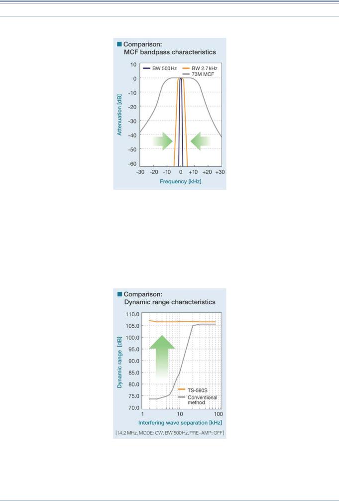
Following is a graph that provides the comparison between the performances of roofing filters.
Figure 1-5 Comparison of Bandpass Characteristics of MCFs
Figure 1-5 compares the band pass characteristics of a roofing filter of center frequency 73 MHz (gray line); and the roofing filters of the center frequency 11.374 MHz with bandwidth of 500 Hz (blue line) and with bandwidth of 2.7 kHz (orange line) that are both employed by the TS-590S.
Because the center frequency of the filters differ, graphs are overlapped at the center frequency. The frequency indicated as 0 kHz at the center of the Frequency [kHz] axis is the receive frequency.
It is apparent that when down conversion is active, large attenuation is achieved at frequencies other than the target signal.
Figure 1-6 Comparison of Dynamic Range Characteristics
Figure 1-6 shows a graph comparing the dynamic range characteristics of TS-590S and TS-480S (with CW filter) that are measured by changing the frequency spacing with the interfering signal.
6 |
CONTENTS |
TS-590S |

1 RECEPTION
Measurement Conditions:
Receive |
14.200 MHz |
|
Frequency |
||
|
||
|
|
|
Mode |
CW |
|
|
|
|
Pass bandwidth |
500 Hz |
|
|
|
|
PRE AMP |
OFF |
|
|
|
The abscissa axis shows the distance from the interfering signal. For example, it represents that at the point of 10 kHz the receive frequency is 14.200 MHz and two interfering signals of 14.210 MHz and 14.220 MHz are given.
The orange line shows the result of TS-590S and the gray line shows the result of TS-480S.
In the event the frequency separation is greater than 20 kHz, the dynamic ranges of both transceivers exceed 105 dB; however, as the separation becomes smaller (the interfering signals come closer to the receive frequency), the dynamic range of TS-480S with conventional MCFs is decreasing. As the graph of pass bandwidth shows, this results due to the difference of attenuation at the roofing filter.
Note: In the receive frequency and its adjacent band, the measurement at the level of “3 dB higher than the ordinary noise level” may not be feasible due to influence of the noise generated from its local oscillator. Instead, the level, which has been reached to S5 with the measurement by an S-meter, is predetermined as the reference level, and the level is converted to the same level as the predetermined level, namely “3 dB higher than the ordinary noise level”, and then appears on the graph of pass bandwidth. For comparison, both transceivers were measured using the same measuring method. The outcome is an example and does not warrant the performance of the product.
TS-590S |
CONTENTS |
7 |
1 RECEPTION
1.3 Up Conversion
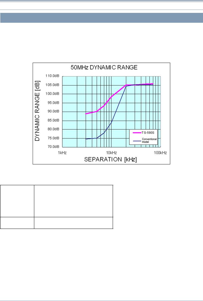
Difference of characteristics due to the pass bandwidth in the roofing filter can be viewed in graphs in Figure 1-5 and Figure 1-6. So, let’s see the characteristics of the up-conversion system in which the same front end configuration is used as previous models. We will explain using the measurement result that compares the dynamic range characteristics of TS-590S and of previous models in the 50 MHz band.
Figure 1-7 Dynamic Range in the 50 MHz Band
Measurement Conditions:
Receive |
50.200 MHz |
|
Frequency |
||
|
||
|
|
|
Mode |
CW |
|
|
|
|
Pass bandwidth |
500 Hz |
|
|
|
|
PRE AMP |
OFF |
Comparison
target
(The measurement method is the same as that was applied to 14.2 MHz.)
In the 50 MHz band, the signal is received with up conversion on both the TS-590S and the TS-480S. If the separation between the target signal and the interfering signal drops below 20 kHz, the dynamic range decreases on both transceivers. However, on the TS-590S, the outcome is improved for 15 dB even within the pass bandwidth of the MCF.
This is thanks to the drastic modification of circuitry of the up-conversion section that was reviewed coupled with the down-conversion path being added.
The same circuit is also used in WRC bands and in general coverage receiving as well as in the 50 MHz band, and therefore the equivalent performance improvement is made in those bands.
8 |
CONTENTS |
TS-590S |

1 RECEPTION
1.4 RX Auxiliary Circuits
Typical built-in RX auxiliary circuits include the variable pass bandwidth circuit, notch filter and noise blanker (NB). In modern HF transceivers, most of these auxiliary circuits (=auxiliary functions) are made possible by an arithmetic process of the DSP. As well as the TS-590S, only two auxiliary circuits operate genuinely at the IF stage: NB and AGC (ATT circuit that functions by receiving the control signal provided by the DSP).
On the TS-590S, there are two methods available to achieve noise blanking: NB1 and NB2. NB1 is realized by analog processing and NB2 by digital processing of the IF DSP. Still retaining an analog noise blanker, TS-590S may seem out of step with the times. But it is critical to have an analog noise blanker for a receiving system design using narrow roofing filters.
Noise is typically pulse-shaped and when the noise passes a narrow filter, the pulse waveform is changed to have a wider (longer) pulse width.
Within the DSP, the processing block of the noise blanker is placed in a stage earlier than the filter block that determines the final pass bandwidth. Thus, even if the final pass bandwidth is narrowed, the blanking operation can work properly, free of the influence of the narrowed bandwidth.
However, roofing filters are located far earlier than the DSP, in the later stage of the first mixer. As a result, in the event the bandwidth of the roofing filter becomes as narrow as 500 Hz, the pulse width becomes wider and a conventional digital noise blanker would not deliver a sufficient blanking effect.
This is the exact case while down conversion is active on the TS-590S and a digital noise blanker alone may not produce a great enough effect. That is the reason we have placed a filter of pass bandwidth 6 kHz right after the first mixer. The filter deters the transformation of the pulse shape and prevents false operation of the noise blanker due to adjacent signals while sending the noise signals to the analog noise blanker.
During the up conversion, the noise signal is derived from the second IF stage and delivered to the noise blanker circuit as in previous models.
Hints and Tips “What are NB1 and NB2?”
NB1and NB2 are the name of the functions that have been used in TS-930S and all subsequent products. NB2 was especially designed to have a blanking effect against noise with a long pulse width and a long period that has been known as the “Woodpecker.” After the woodpecker noise disappeared, the NB2 function was not employed, but in recent years a new breed of noise called the “China Dragon” has appeared. So, there may be cases when NB1 alone may not have a great enough effect on the China Dragon, NB2 has been spotlighted again. Note, however, NB2 on the TS-590S is realized with digital processing and, thereafter, totally different from NB2 in the TS-930S era.
As explained above, while the narrow bandwidth of the roofing filter is employed, the noise blanker of the DSP cannot have a sufficient effect. However, the NB2 realized with the DSP on the TS-590S turns out to be unexpectedly effective in many occasions, even while the bandwidth is less than 500 Hz in CW mode. This is because the new NB2 can fully adjust the blanking time to the length of the pulse.
NB2 of the TS-590S is most effective when you want to pick up a weak signal that is almost buried in the noise with a long pulse width that cannot be eliminated by NB1. Try NB2 in such occasions and be surprised.
Hints and Tips “Improvement of sensitivity in the BC band and alteration in ATT attenuation”
On the TS-590S, by changing the circuitry configuration inside the transceiver, you can change the sensitivity in the BC band and the attenuation amount of the [ATT] key on the front panel.
TS-590S |
CONTENTS |
9 |

1 RECEPTION
Following is a figure that represents the TX-RX UNIT that has the circuitry configuration in question. By detaching the lower case, you can access the jumper connectors CN101 through CN103.
CN101
CN102
CN103
Figure 1-8 TX-RX UNIT
1)Raising sensitivity in the BC band:
Remove the jumper for CN103 and insert the jumper into CN102. This will increase the sensitivity in the BC band for 20 dB. (Assuming that there is the high output power in local broadcasting stations in the BC band, the sensitivity is lowered by 20 dB as the is factory default.)
2)Changing the attenuation amount of ATT:
Remove the jumper of CN101. This changes the attenuation of ATT from 12 dB to 20 dB. (Store the removed jumper in a secure place for future use.)
Hints and Tips “The output level of the headphone jack is too high?”
The headphone jack of the TS-590S is designed to have, as on the previous HF transceivers, an impedance of 8 (standard). Therefore, if you use a headphone with impedance higher than 8 , you will experience the symptoms as below.
•The volume level is too high overall.
•Even if AF Volume is turned down, a hissing residual noise is audible.
•Even if the beep sound level is set to minimum, the beep sound is loud.
If you experience these symptoms, use a set of headphones with impedance close to 8 .
10 |
CONTENTS |
TS-590S |

2 TRANSMISSION
2.1 Kenwood Traditional Transmitting Circuitry
The tradition of high quality audio technology that users rely on Kenwood to deliver is produced by combining analog and digital technologies that Kenwood has nurtured thus far. The DSP controls modulation and determines the sound quality and analog circuits convey and amplify the signal cleanly.
 2.1.1 IF Circuits
The first IF transmit signal that is output at 24 kHz from the DSP and the DA converter is converted to 10.695 MHz in a dedicated IC for the mixer. The second IF signal at 10.695 MHz passes an IF filter of 6 kHz bandwidth at which undesired frequency components outside the pass bandwidth are attenuated before the signal is amplified. Then, the second IF signal passes to the ALC circuit that controls the output power to a stable level. After that, the signal goes through the gain control circuit that corrects the minutely small differences in gain from band to band, and the signal enters the mixer that is commonly used in TX and RX, and is converted to the third IF of 73.095 MHz. The signal passes the gain control circuit that adjusts the signal to the necessary gain level according to the specified power level. Then, the signal passes the filter that eliminates spurious components before going into the mixer circuit that converts the signal to the desired transmit frequency. Also, delicate gain control is done, such as decreasing the gain of the amplifier while the key is not depressed in CW mode. By means of these processes, a high-quality transmit signal with low noise can be acquired. The signal converted to the desired transmit frequency passes the BPF for removing spurious signals to prevent from generating interfering signals outside of the transmit bandwidth, and is amplified to a prescribed level before being sent to the final circuit. The drive signal produced here can be extracted from the DRV terminal. (While the output from DRV is selected.)
 2.1.2 FET Final Circuit
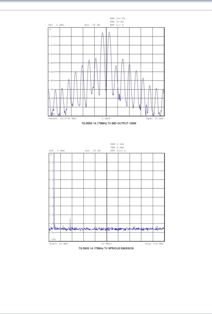
The final amplifier of the TS-590S is a push-pull amplifier using two pieces of RD100HHF1 MOSFET from Mitsubishi Electric Semiconductor (Pch 176.5 W). The drive amplifier also uses an RD100HHF1 MOSFET and the pre-drive amplifier employs an RD06HHF1 MOSFET and they, despite being 13.8V final circuits, amplify the signal reasonably in a stable and continuous manner with low distortion. Figure 2-1 shows the graph of IMD characteristics and Figure 2-2 shows the graph of harmonic spurious characteristics. Superior distortion characteristics and clean signals are acquired in this way.
TS-590S |
CONTENTS |
11 |
2 TRANSMISSION
Figure 2-1 Transmit IMD Characteristics
Figure 2-2 Transmit Spurious Characteristics
12 |
CONTENTS |
TS-590S |

2 TRANSMISSION
2.2 High-speed Relay-controlled Antenna Tuner
TS-590S has a built-in high-speed relay-controlled antenna tuner that was first employed in the TS-570S. In contrast to the variable capacitor type antenna tuner, it employs a small and lightweight relay to achieve a sufficient matching range and a fast tuning operation with digital control. The control speed has been further accelerated over previous models. When you return to a previously used operating band or frequency, the antenna tuner easily and quickly re-tunes.
2.3 REMOTE Connector
The transceiver has a REMOTE connector that has the same pin assignment and specifications as on previous models.
Pin 6 is the ALC terminal. When you use a linear amplifier or transverter, we recommend you connect the external accessory device to the ALC terminal in order to control the output to be within an appropriate range.
The ALC signal is a signal to shift the voltage in the minus direction (in Kenwood’s devices) when the output level requires regulation to satisfy the requirements of the external accessory device. Generally external accessory devices have a VR for adjusting the voltage. In the TS-590S, a negative voltage (approximately -10 V) is applied to the ALC terminal to decrease the internal gain.
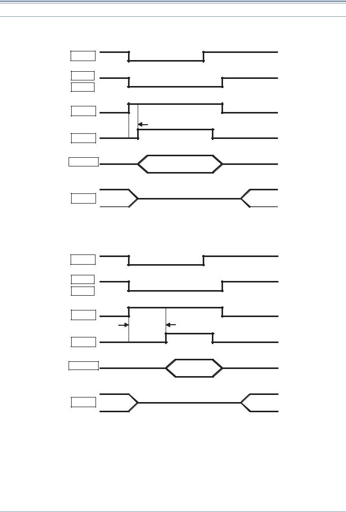
As well, for the purpose of controlling a linear amplifier and other external device, the transceiver is equipped with a relay output terminal and an RL terminal (Pin 7) to which an approximately 12 V voltage is output. The relay output and RL terminal output are coordinated with internal controls and can be adjusted in the linear amplifier control setting menu No. 53 (HF bands) or No. 54 (50 MHz band). Table 2-1 describes the possible settings of the menu, and Figure 2-3 and Figure 2-4 provide the timing charts.
If using equipment that is not designed for full break-in and requires a delay for internal switchover, such as TL-922, select “3”. In this way, you can increase the delay between the case when the transceiver is switched to transmit and the case when the signal is actually sent out. Note; however, if the full break-in setting is selected in CW mode (and if the delay time is set to “FBK”), the transmit start time cannot be delayed.
Table 2-1 Setting Menu of Linear Amplifier Control
Linear Amplifier Controls
Setting |
Control of Linear |
Control of Relay (COM/ |
Transmit Start Delay Time |
|
Amplifier (RL terminal) |
BRK/MKE terminals) |
|||
|
|
|||
|
|
|
|
|
OFF |
OFF |
OFF |
10 ms |
|
|
|
|
|
|
1 |
ON |
OFF |
10 ms |
|
|
|
|
|
|
2 |
ON |
ON |
10 ms |
|
|
|
|
|
|
3 |
ON |
ON |
25 ms |
|
|
|
|
|
TS-590S |
CONTENTS |
13 |
2 TRANSMISSION
Menu N o. 53 or N o. 54 "1 or 2"
KEY
RX
TX
RL
10 ms
Switch
RF Power
AF
Figure 2-3 Timing chart (1 or 2)
Menu N o. 53 or N o. 54 "3"
KEY
RX
TX
RL
25 ms
Switch
RF Power
AF
Figure 2-4 Timing chart (3)
14 |
CONTENTS |
TS-590S |
2 TRANSMISSION
2.4 DRV Terminal
TS-590S is equipped with a DRV terminal that formerly was provided only for high-end transceivers.
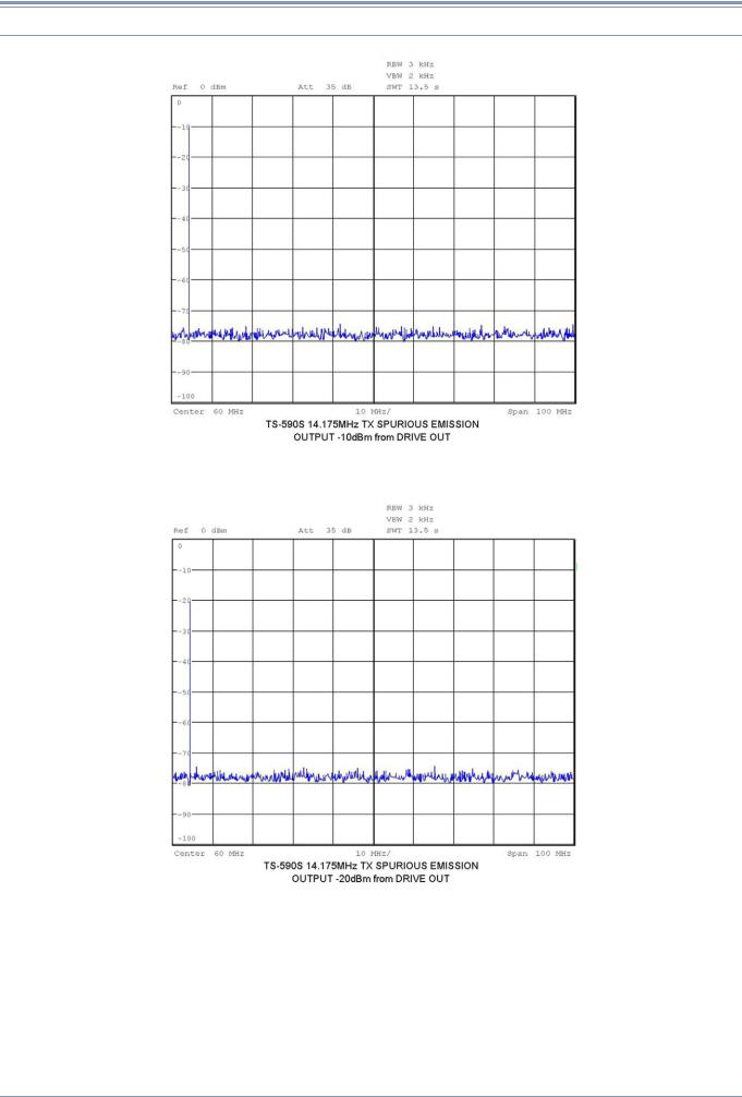
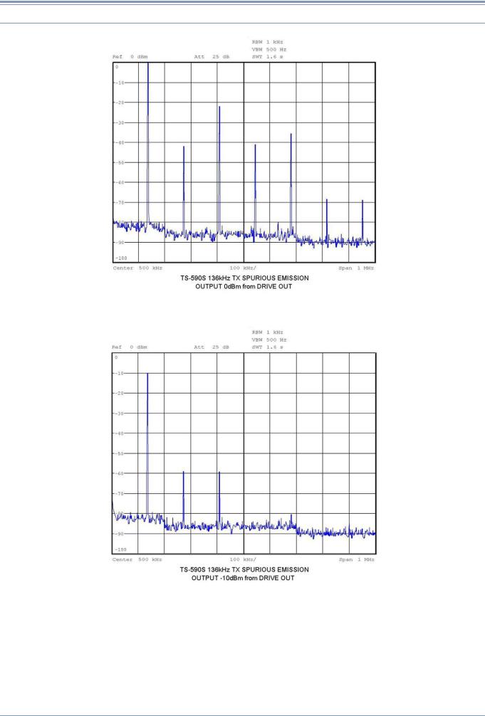
The output level of the DRV terminal is about 0 dBm (1 mW) and can be decreased to around 1/20 depending on the setting of the transmit power. To reduce the output level further, you can adjust the transmit power also by the carrier level in CW, FSK and AM modes or by the microphone gain or processor output level in SSB mode. The output level of the signal from the terminal is too low to be transmitted as is, but by connecting a high-gain linear amplifier, the signal can be used for operation in the 135 kHz band or for operation with a transverter. Figure 2-5 through Figure 2-7 show the spurious characteristics when using the signal from the DRV terminal in the 14 MHz band and Figure 2-8 through Figure 2-10 show the spurious characteristics in the 135 kHz band. If the output level is 0 dBm in the 135 kHz band, the harmonics increase slightly; therefore, you need to place an LPF after the amplifier or in some other way eliminate the harmonics. Also, lowering the setting of the transmit output level or limiting the output level at the DRV terminal by entering the ALC signal will also contribute to reduce distortion.
Figure 2-5 Output Characteristics of DRV Terminal at 14.175 MHz and 0 dBm
TS-590S |
CONTENTS |
15 |
2 TRANSMISSION
Figure 2-6 Output Characteristics of DRV Terminal at 14.175 MHz and -10 dBm
Figure 2-7 Output Characteristics of DRV Terminal at 14.175 MHz and -20 dBm
16 |
CONTENTS |
TS-590S |
2 TRANSMISSION
Figure 2-8 Output Characteristics of DRV Terminal at 136 kHz and 0 dBm
Figure 2-9 Output Characteristics of DRV Terminal at 136 kHz and -10 dBm
TS-590S |
CONTENTS |
17 |
Loading...