


TS570D

TS-570S
4 6
2
L
O
W
C
U
T
4 6
2
PF
ATT PRE-AMP
VOX PROC
SEND
CH1
MIC
CW
FSK
LSB
USB
FM
AM
AT TUNE
HF TRANSCEIVER TS-570D
PHONES
1
CH2
2
CH3
3
ANT
4
REC
5
FINE
6
NB
7
AGC/TONE
8
REV
9
CLR
F.LOCK
0
ENT
MIC
PWR
KEY
DELAY MENU
1MHz
SPLIT
M/V
DOWN
UP
MR
TF-SET
A=B
SCAN M>VFO M.IN
M.IN
FILTER
CW TUNE
B.C.
N.R.
A/B
CLEAR
RIT
XIT
RIT/XIT
IF SHIFT SQL
CH
0 10
8
A F R F
HIGH
DSP SLOPE
LOW
0 10
8
+–
© B62-1542-00 (K,E,M)(MC)
09 08 07 06 05 04 03 02 01 00
KENWOOD CORPORATION
INSTRUCTION MANUAL
ALL MODE MULTI-BANDER
TS-570D
HF TRANSCEIVER
Intelligent Digital Enhanced Communications System
INFORMATION TO THE DIGITAL DEVICE USER REQUIRED
BY THE FCC
This equipment has been tested and found to comply with the
limits for a Class B digital device, pursuant to Part 15 of the FCC
Rules. These limits are designed to provide reasonable
protection against harmful interference in a residential
installation.
This equipment generates, uses and can generate radio
frequency energy and, if not installed and used in accordance
with the instructions, may cause harmful interference to radio
communications. However, there is no guarantee that the
interference will not occur in a particular installation. If this
equipment does cause harmful interference to radio or television
reception, which can be determined by turning the equipment off
and on, the user is encouraged to try to correct the interference
by one or more of the following measures:
•
Reorient or relocate the receiving antenna.
•
Increase the separation between the equipment and
receiver.
•
Connect the equipment to an outlet on a circuit different from
that to which the receiver is connected.
•
Consult the dealer for technical assistance.
FCC WARNING
This equipment generates or uses radio frequency energy.
Changes or modifications to this equipment may cause harmful
interference unless the modifications are expressly approved in
the instruction manual. The user could lose the authority to
operate this equipment if an unauthorized change or modification
is made.
APPLICABLE MODEL
This manual applies to the following model:
TS-570S: All mode multi-bander
TS-570D: HF Transceiver
Intelligent Digital Enhanced Communications System
SUPPLIED ACCESSORIES
Carefully unpack the transceiver. We recommend that
you identify the items listed in the table below. In
addition, it is safe to keep the box and the packing
material. You may need to repack the transceiver in
the future.
NOTICE TO THE USER
One or more of the following statements may be
applicable to this equipment.
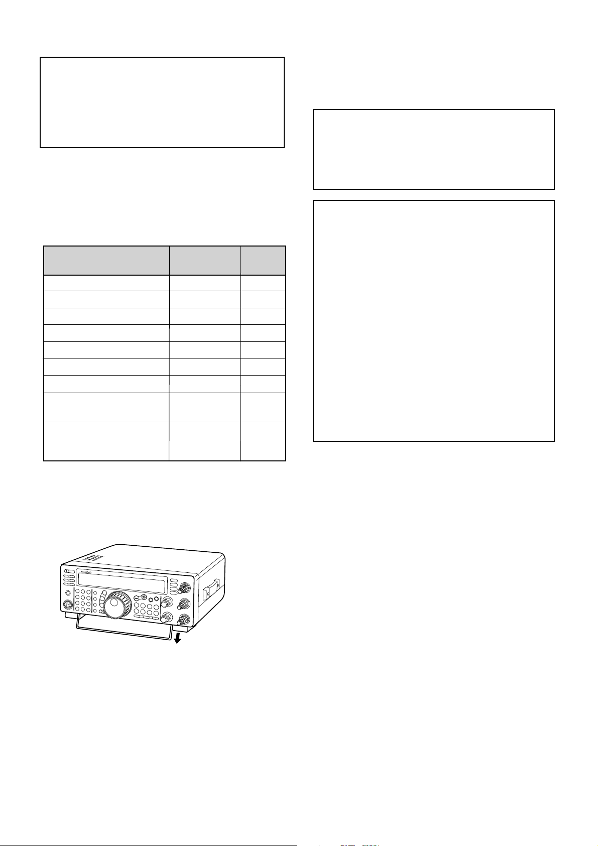
This transceiver is equipped with a bail on the bottom so
that you can angle the transceiver. Pull the bail forward
to the limit as shown:
Microphone
DC power cable
7-pin DIN plug
13-pin DIN plug
Fuse (25 A)
Fuse (4 A)
Instruction manual
Schematic/block diagrams
(U.S.A. and Canada only)
Warranty card
(U.S.A., Canada, and
Europe only)
1
1
1
1
1
1
1
1
1
Accessory
Part Number
Quantity
1
1
T91-0352-XX
E30-3157-XX
E07-0751-XX
E07-1351-XX
F05-2531-XX
F06-4027-XX
B62-1542-XX
—
—
For other markets, schematic and block diagrams are
available as options.
i
Thank you for choosing the KENWOOD TS-570 series.
This Intelligent Digital Enhanced Communications
System was developed by a team of engineers
determined to continue the tradition of excellence and
innovation in KENWOOD HF transceivers.
This transceiver includes a 16-bit Digital Signal
Processing (DSP) unit to process audio frequencies. By
taking maximum advantage of DSP technology the
transceiver gives you enhanced interference reduction
capabilities and improves the quality of audio that you
transmit. You will find the differences when you fight
QRM and QRN in the new solar cycle. As you learn
how to use this transceiver, you also will find
KENWOOD is pursuing “user friendliness”. For
example, each time you change the Menu No. in Menu
mode, you will see, on the display, scrolling messages
that tell what you are selecting.
Though user friendly, this transceiver is technically
sophisticated and some features may be new to you.
Consider this manual to be a personal tutorial from the
designers. Allow the manual to guide you through the
learning process now, then act as a reference in the
coming years.
FEATURES
Taking full advantage of DSP technology, this
transceiver
• Provides high performance receive filters.
• Enhances the Beat Cancel and Noise Reduction
tools.
• Allows total customization of transmitted audio
through the use of functions such as the Transmit
Equalizer.
• Enables Automatic Zero-beating for CW operation.
To pursue user friendliness, this transceiver
• When in Menu mode, scrolls messages to tell you
what you are selecting.
• Allows you to quickly and easily save the current
transceiver settings in Quick memory.
• Is equipped with a large, easy to read LCD display.
WRITING CONVENTIONS FOLLOWED
The writing conventions described below have been
followed to simplify instructions and avoid unnecessary
repetition. This format is less confusing for the reader.
Reviewing the following information now will reduce
your learning period. That means less time will be
spent reading this manual; more time will be available
for operating.
Furthermore, a system of advisories is used as follows:
WARNING!
➡ Possibility of personal injury
CAUTION:
➡ Possibility of equipment damage
Note:
➡ Important information or operating tip
Note:
Basic procedures are numbered sequentially to guide you
step-by-step. Additional information pertaining to a step, but not
essential to complete the procedure, is provided in bulleted form
following many steps.
THANK YOU
Instruction What to Do
Press and release KEY.
Press and hold KEY1 down,
then press KEY2. If there are
more than two keys, press and
hold down each key in turn
until the final key has been
pressed.
Press KEY1 momentarily,
release KEY1, then press
KEY2.
With the transceiver power
OFF, press and hold KEY,
then switch ON the transceiver
power by pressing the
[ ] (POWER) switch.
Press [KEY].
Press
[KEY1]+[KEY2].
Press
[KEY1], [KEY2].
Press
[KEY]+[ ].

ii
PRECAUTIONS IV
CHAPTER 1 INSTALLATION 1
ANTENNA CONNECTION ....................................... 1
GROUND CONNECTION ........................................ 2
LIGHTNING PROTECTION ..................................... 2
DC POWER SUPPLY CONNECTION ...................... 2
REPLACING FUSES ........................................... 2
ACCESSORY CONNECTIONS ............................... 3
FRONT PANEL .................................................... 3
Headphones (PHONES) ................................. 3
Microphone (MIC) ........................................... 3
REAR PANEL ...................................................... 3
External Speaker (EXT SP) ............................ 3
Keys and Keyboards for
CW Operation (PADDLE and KEY) ................. 3
CHAPTER 2 YOUR FIRST QSO 4
RECEIVING ............................................................. 4
TRANSMITTING ...................................................... 5
CHAPTER 3 GETTING ACQUAINTED 6
FRONT PANEL ........................................................ 6
MICROPHONE ........................................................ 9
REAR PANEL ........................................................ 10
DISPLAY ............................................................... 11
CHAPTER 4 OPERATING BASICS 13
SWITCHING POWER ON/OFF ............................. 13
ADJUSTING VOLUME .......................................... 13
AUDIO FREQUENCY (AF) GAIN....................... 13
RADIO FREQUENCY (RF) GAIN ...................... 13
SELECTING VFO A OR VFO B ............................. 13
SELECTING A BAND ............................................ 13
SELECTING A MODE ........................................... 14
ADJUSTING SQUELCH ........................................ 14
SELECTING A FREQUENCY ................................ 14
FRONT PANEL METER ........................................ 14
TRANSMITTING .................................................... 15
SELECTING TRANSMIT POWER ..................... 15
MICROPHONE GAIN ........................................ 15
CHAPTER 5 MENU SETUP 16
WHAT IS A MENU? ............................................... 16
MENU A/ MENU B ................................................. 16
MENU ACCESS .................................................... 16
MENU CONFIGURATION ..................................... 17
CROSS REFERENCE FOR
MENU FUNCTIONS .............................................. 19
CHAPTER 6 BASIC COMMUNICATING 20
SSB TRANSMISSION ........................................... 20
CW TRANSMISSION ............................................ 21
AUTO ZERO-BEAT ........................................... 21
TX SIDETONE/ RX PITCH FREQUENCY ......... 21
FM TRANSMISSION ............................................. 22
TX DEVIATION SELECTION ............................. 22
CONTENTS
AM TRANSMISSION ............................................. 22
CHAPTER 7 SPECIALIZED COMMUNICATING 23
SPLIT-FREQUENCY OPERATION ........................ 23
TF-SET (TRANSMIT FREQUENCY SET) .......... 23
FM REPEATER OPERATION ................................ 24
SELECTING SUBTONE FREQUENCY ............. 25
CONTINUOUS OR BURST SUBTONES? ......... 25
FM CTCSS OPERATION ....................................... 25
DIGITAL OPERATION ........................................... 26
RTTY (FREQUENCY SHIFT KEYING) .............. 26
AMTOR/ PACKET/ PACTOR/ G-TOR
TM
/ CLOVER . 27
SLOW SCAN TV/ FACSIMILE ............................... 28
SATELLITE OPERATION ...................................... 28
CHAPTER 8 COMMUNICATING AIDS 29
RECEIVING ........................................................... 29
SELECTING YOUR FREQUENCY .................... 29
Direct Frequency Entry ................................. 29
Using 1 MHz Steps ....................................... 29
Quick Changes ............................................. 29
Fine Tuning................................................... 29
Equalizing VFO Frequencies (A=B) .............. 30
RIT (RECEIVE INCREMENTAL TUNING) ......... 30
AGC (AUTOMATIC GAIN CONTROL) ............... 30
RX EQUALIZER ................................................ 30
TRANSMITTING .................................................... 31
VOX (VOICE-OPERATED TRANSMIT) ............. 31
Microphone Input Level ................................. 31
Delay Time ................................................... 31
SPEECH PROCESSOR .................................... 32
XIT (TRANSMIT INCREMENTAL TUNING) ....... 32
CUSTOMIZING TRANSMIT SIGNAL
CHARACTERISTICS ......................................... 33
Changing Transmit
Bandwidth (SSB/AM) .................................... 33
Equalizing Transmit Audio (SSB/FM/AM) ...... 33
MONITORING TRANSMITTED SIGNALS ......... 33
TRANSMIT INHIBIT ........................................... 33
CHANGING FREQUENCY WHILE
TRANSMITTING ................................................ 33
CW BREAK-IN ....................................................... 34
USING SEMI BREAK-IN OR
FULL BREAK-IN ................................................ 34
ELECTRONIC KEYER .......................................... 34
CHANGING KEYING SPEED ............................ 34
AUTO WEIGHTING ........................................... 34
Reversible Auto Weighting ............................ 34
CHANGING LOCKED-WEIGHT ........................ 35
BUG KEY FUNCTION ....................................... 35
CW MESSAGE MEMORY ................................. 35
Storing CW Messages .................................. 35
Checking CW Messages without Transmitting35
Transmitting CW Messages .......................... 35
CHAPTER 9 REJECTING INTERFERENCE 36
IF FILTER .............................................................. 36
CHANGING IF FILTER BANDWIDTH ................ 36
IF SHIFT ............................................................ 36
NOISE BLANKER .................................................. 36
iii
Transferring Data .......................................... 50
Receiving Data ............................................. 50
COMPUTER CONTROL ........................................ 51
SETTING UP ..................................................... 51
Equipment Needed ....................................... 51
Connections ................................................. 51
COMMUNICATION PARAMETERS ................... 51
USING A TRANSVERTER ..................................... 51
AUTOMATIC ANTENNA TUNER ........................... 52
PRESETTING ................................................... 52
DRU-3A DIGITAL RECORDING UNIT
(OPTIONAL) .......................................................... 53
RECORDING MESSAGES ................................ 53
MESSAGE PLAYBACK ..................................... 53
Checking Messages ..................................... 53
Sending Messages ....................................... 54
Changing Inter-message Interval .................. 54
Changing Volume ......................................... 54
VS-3 VOICE SYNTHESIZER (OPTIONAL) ............ 55
CHAPTER 13 OPTIONAL ACCESSORIES 56
CHAPTER 14 INSTALLING OPTIONS 57
REMOVING THE BOTTOM CASE ........................ 57
DRU-3A DIGITAL RECORDING UNIT ................... 57
VS-3 VOICE SYNTHESIZER UNIT ........................ 58
YK-88C-1/ YK-88CN-1/ YK-88SN-1 FILTERS ........ 58
SO-2 TEMPERATURE-COMPENSATED CRYSTAL
OSCILLATOR (TCXO) ........................................... 59
CHAPTER 15 CONNECTING PERIPHERAL EQUIPMENT 60
COMPUTER .......................................................... 60
COMPATIBLE TRANSCEIVER .............................. 60
RTTY EQUIPMENT ............................................... 61
LINEAR AMPLIFIER .............................................. 61
ANTENNA TUNER ................................................ 61
MCP AND TNC ...................................................... 62
CHAPTER 16 MAINTENANCE 63
GENERAL INFORMATION .................................... 63
SERVICE ........................................................... 63
SERVICE NOTE ................................................ 63
CLEANING ........................................................ 63
INTERNAL ADJUSTMENTS .................................. 64
REFERENCE FREQUENCY CALIBRATION ..... 64
ACCESSING THE INTERNAL FUSE................. 64
TROUBLESHOOTING ........................................... 65
SPECIFICATIONS 68
APPENDIX: COM CONNECTOR PROTOCOL 70
INDEX 82
ATTENUATOR ....................................................... 37
PREAMPLIFIER .................................................... 37
DSP TOOLS .......................................................... 37
CHANGING RECEIVE BANDWIDTH ................ 37
SSB/ FM/ AM Modes .................................... 37
CW/ FSK Modes ........................................... 38
BEAT CANCEL .................................................. 38
NOISE REDUCTION ......................................... 38
Changing NR1 Performance ......................... 38
Setting NR2 Time Constant........................... 38
CHAPTER 10 MEMORY FEATURES 39
MICROPROCESSOR MEMORY BACKUP............ 39
CONVENTIONAL MEMORY.................................. 39
STORING DATA IN MEMORY ........................... 39
Simplex Channels ......................................... 39
Split-Frequency Channels ............................. 40
MEMORY RECALL AND SCROLL .................... 40
Memory Recall .............................................. 40
Memory Scroll ............................................... 41
Temporary Frequency Changes .................... 41
Memory-VFO Split Operation ........................ 41
MEMORY TRANSFER ...................................... 42
Memory ➡ VFO Transfer ............................. 42
Channel ➡ Channel Transfer ....................... 42
STORING FREQUENCY RANGES ................... 43
Confirming Start/End Frequencies ................ 43
Programmable VFO ...................................... 43
ERASING MEMORY CHANNELS ..................... 43
Full Reset ..................................................... 43
Memory Channel Lockout ............................. 44
QUICK MEMORY .................................................. 44
STORING INTO QUICK MEMORY .................... 44
RECALLING QUICK MEMORY ......................... 45
TEMPORARY FREQUENCY CHANGES .......... 45
QUICK MEMORY ➡ VFO TRANSFER .............. 45
CHAPTER 11 SCAN 46
PROGRAM SCAN ................................................. 46
SCAN HOLD ..................................................... 46
MEMORY SCAN ................................................... 47
ALL-CHANNEL SCAN ....................................... 47
GROUP SCAN .................................................. 47
CHAPTER 12 OPERATOR CONVENIENCES 48
MICROPROCESSOR RESET ............................... 48
INITIAL SETTINGS ............................................ 48
PARTIAL RESET ............................................... 48
FULL RESET ..................................................... 48
SWITCHING ANT 1/ ANT 2.................................... 48
FREQUENCY LOCK FUNCTION .......................... 48
BEEP FUNCTION .................................................. 49
DISPLAY DIMMER ................................................ 49
PROGRAM FUNCTION BUTTON ......................... 49
QUICK DATA TRANSFER ..................................... 50
SETTING UP ..................................................... 50
Equipment Needed ....................................... 50
Connections ................................................. 50
USING QUICK TRANSFER ............................... 50
iv
PRECAUTIONS
Please read all safety and operating instructions before
using this transceiver. For best results, be aware of all
warnings on the transceiver and follow these operating
instructions. Retain these safety and operating
instructions for future reference.
1 Power Source
Connect this transceiver only to the power source
described in the operating instructions or as marked
on the transceiver itself.
2 Power Cable Protection
Route all power cables safely. Ensure the power
cables can neither be walked upon nor pinched by
items placed near or against the cables. Pay
particular attention to locations near AC receptacles,
AC outlet strips and points of entry to the transceiver.
3 Electrical Shocks
Take care not to drop objects or spill liquids into the
transceiver through enclosure openings. Metal
objects, such as hairpins or needles, inserted into
the transceiver may contact voltages resulting in
serious electrical shocks. Never permit children to
insert any objects into this transceiver.
4 Grounding and Polarization
Do not attempt to defeat methods used for
grounding and electrical polarization in the
transceiver, particularly involving the input power
cable.
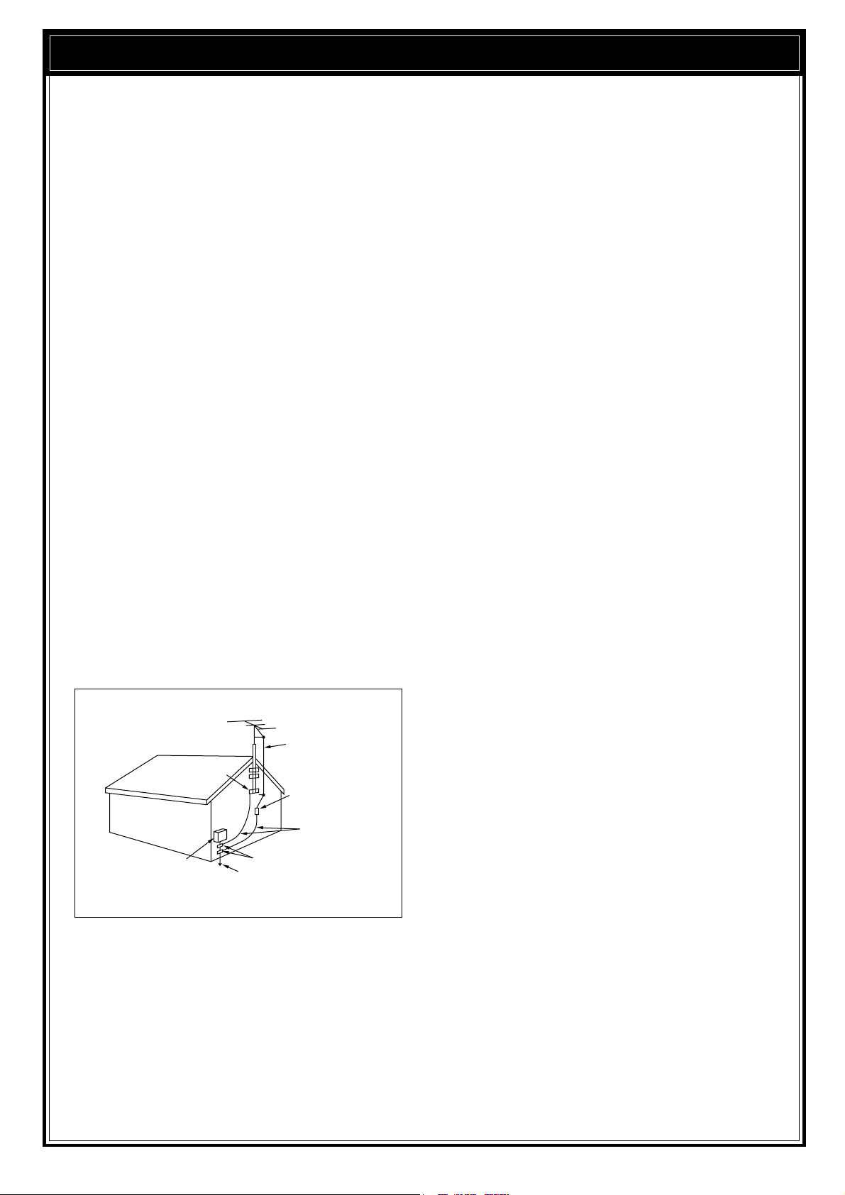
5 Outdoor Antenna Grounding
Adequately ground all outdoor antennas used with
this transceiver using approved methods.
Grounding helps protect against voltage surges
caused by lightning. It also reduces the chance of a
build-up of static charges.
6 Power Lines
Minimum recommended distance for an outdoor
antenna from power lines is one and one-half times
the vertical height of the associated antenna support
structure. This distance allows adequate clearance
from the power lines if the support structure should
fail for any reason.
7Ventilation
Locate the transceiver so as not to interfere with its
ventilation. Do not place books or other equipment
on the transceiver that may impede the free
movement of air. Allow a minimum of 4 inches
(10cm) between the rear of the transceiver and the
wall or operating desk shelf.
8Water and Moisture
Do not use the transceiver near water or sources of
moisture. For example, avoid use near bathtubs,
sinks, swimming pools, and in damp basements and
attics.
9 Abnormal Odors
The presence of an unusual odor or smoke is often a
sign of trouble. Immediately turn the power OFF and
remove the power cable. Contact a dealer or the
nearest Service Center for advice.
10 Heat
Locate the transceiver away from heat sources such
as radiators, stoves, amplifiers or other devices that
produce substantial amounts of heat.
11 Cleaning
Do not use volatile solvents such as alcohol, paint
thinner, gasoline or benzene to clean the cabinet.
Use a clean cloth with warm water or a mild
detergent.
12 Periods of Inactivity
Disconnect the input power cable from the power
source when the transceiver is not used for long
periods of time.
13 Servicing
Remove the transceiver’s enclosure only to do
accessory installations described by this manual or
accessory manuals. Follow provided instructions
carefully to avoid electrical shocks. If unfamiliar with
this type of work, seek assistance from an
experienced individual, or have a professional
technician do the task.
14 Damage Requiring Service
Enlist the services of qualified personnel in the
following cases:
a) The power supply or plug is damaged.
b) Objects have fallen or liquid has spilled into the
transceiver.
c) The transceiver has been exposed to rain.
d) The transceiver is operating abnormally or
performance has degraded seriously.
e) The transceiver has been dropped or the
enclosure damaged.
EXAMPLE OF ANTENNA GROUNDING
ANTENNA
LEAD IN
WIRE
GROUND
CLAMP
ELECTRIC SERVICE
EQUIPMENT
ANTENNA
DISCHARGE UNIT
GROUNDING
CONDUCTORS
GROUND CLAMPS
POWER SERVICE
GROUNDING ELECTRODE
SYSTEM
1
INSTALLATION
ANTENNA CONNECTION
The type of the antenna system, consisting of the
antenna, ground, and feed line, will greatly affect the
successful performance of the transceiver. Use a
properly adjusted 50 Ω antenna of good quality to let
your transceiver perform at its best. Use a good-quality
50 Ω coaxial cable and a first-quality connector for the
connection. Match the impedance of the coaxial cable
and antenna so that the SWR is 1.5:1 or less. All
connections must be clean and tight.
While the transceiver’s protection circuit will activate if
the SWR is greater than 2.5:1, do not rely on protection
to compensate for a poorly functioning antenna system.
High SWR will cause the transmit output to drop, and
may lead to radio frequency interference to consumer
products such as stereo receivers and televisions. You
may even interfere with your own transceiver. Reports
that your signal is garbled or distorted, especially at
peak modulation, may indicate that your antenna
system is not efficiently radiating the transceiver’s
power. If you feel a tingle from the transceiver’s cabinet
or the microphone’s metal fittings when you modulate,
you can be certain that, at the least, your coax
connector is loose at the rear of the radio and, at the
worst, your antenna system is not efficiently radiating
power.
Connect your antenna feed line to ANT1. If you are
using two antennas, connect the second antenna to
ANT2.
CAUTION:
◆
TRANSMITTING WITHOUT FIRST CONNECTING AN
ANTENNA OR OTHER MATCHED LOAD MAY DAMAGE THE
TRANSCEIVER. ALWAYS CONNECT THE ANTENNA TO THE
TRANSCEIVER BEFORE TRANSMITTING.
◆
USE A LIGHTNING ARRESTOR TO PREVENT FIRE,
ELECTRIC SHOCK, OR DAMAGE TO THE TRANSCEIVER.
APPROX. LOSS (dB) PER 30 METERS (100 FEET) OF
CORRECTLY MATCHED 50 Ω LINE
• Use only as a general guide. Specifications may vary
between cable manufacturers.
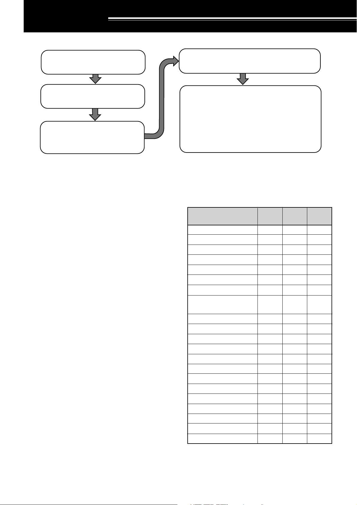
Connect all accessories to the transceiver {pages 3, 60}.
Accessories include the following:
• Microphone
• Antenna Tuner
• CW Key
• Computer
• TNC/ Multimode Communications
Processor
|nstall and connect an antenna system
{page 1}.
Install a ground system that satisfies DC
and RF grounding requirements {page 2}.
Install lightning protection to protect the
antenna system, your personal safety,
and your property {page 2}.
Install and connect a DC power supply {page 2}.
• Headphones
• External Speaker
• RTTY Equipment
• Linear Amplifier
6.4
2.6
2.3
2.3
2.1
2.0
1.4
1.2
1.0
0.90
0.90
0.72
0.70
0.68
0.54
0.45
0.48
0.40
0.39
0.32
0.26
4.3
1.6
1.5
1.5
1.4
1.0
0.93
0.80
0.80
0.60
0.60
0.50
0.48
0.48
0.37
0.33
0.29
0.26
0.25
0.21
0.16
2.3
0.75
0.80
0.65
0.70
0.50
0.45
0.38
N/A
0.29
0.29
0.24
0.24
N/A
N/A
N/A
0.13
0.12
< 0.10
< 0.10
< 0.10
RG-174, -174A
RG-58A, -58C
3D-2V
RG-58, -58B
RG-58 Foam
RG-8X
5D-2V
RG-8, -8A, -9, -9A, -9B,
-213, -214, -215
5D-FB
RG-8 Foam
8D-2V
10D-2V
9913
8D-FB
10D-FB
12D-FB
RG-17, -17A
1/2" Hardline
20D-2V
3/4" Hardline
7/8" Hardline
Transmission Line
3.5 MHz
14 MHz 30 MHz
N/A: Not available
2
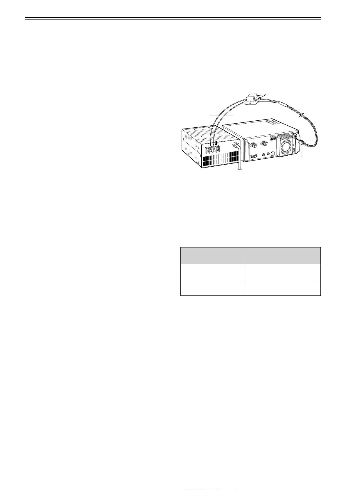
First connect the DC power cable to the regulated DC
power supply and check that polarities are correct
(Red: positive, Black: negative). Then connect the
connectorized end of the DC power cable to the
DC13.8V power connector on the transceiver rear
panel. Press the DC power cable connector firmly into
the connector on the transceiver until the locking tab
clicks.
REPLACING FUSES
If the fuse blows, determine the cause then correct the
problem. After the problem is resolved, only then
replace the fuse. If newly installed fuses continue to
blow, disconnect the power plug and contact your
dealer or nearest Service Center for assistance.
CAUTION:
REPLACE BLOWN FUSES ONLY AFTER
INVESTIGATING AND CORRECTING THE CAUSE OF THE
FAILED FUSE. ALWAYS REPLACE A BLOWN FUSE BY A NEW
FUSE WITH THE SPECIFIED RATINGS.
1 INSTALLATION
GROUND CONNECTION
At the minimum, a good DC ground is required to
prevent such dangers as electric shock. For superior
communications results, a good RF ground is required,
against which the antenna system can operate. Both of
these conditions can be met by providing a good earth
ground for your station. Bury one or more ground rods,
or a large copper plate under the ground, and connect
this to the transceiver GND terminal. Use heavy gauge
wire or a copper strap, cut as short as possible, for this
connection. Just as for antenna work, all connections
must be clean and tight.
LIGHTNING PROTECTION
Consider carefully how to protect your equipment and
your home from lightning. Even in areas where
lightning storms are less common, there are usually a
limited number of storms each year. Take the time to
study the best way to protect your installation from the
effects of lightning by consulting reference material on
the subject.
The installation of a lightning arrestor is a start, but there
is more that you can do. For example, terminate your
antenna system transmission lines at an entry panel
that you install outside your home. Ground this entry
panel to a good outside ground, and then connect
appropriate feed lines between the entry panel and your
transceiver. When a lightning storm occurs, you can
ensure added protection by disconnecting the feed lines
from your transceiver.
CAUTION:
DO NOT ATTEMPT TO USE A GAS PIPE (WHICH IS
CLEARLY DANGEROUS), AN ELECTRICAL CONDUIT (WHICH
HAS THE WHOLE HOUSE WIRING ATTACHED AND MAY ACT
LIKE AN ANTENNA), OR A PLASTIC WATER PIPE FOR A
GROUND.
DC POWER SUPPLY CONNECTION
In order to use this transceiver, you will need a separate
13.8 V DC power supply that must be purchased
separately. DO NOT directly connect the transceiver to
an AC outlet! Use the supplied DC power cable to
connect the transceiver to a regulated power supply. Do
not substitute a cable with smaller gauge wires. The
current capacity of your power supply must be 20.5 A
peak or more.
CAUTION:
◆
BEFORE CONNECTING THE DC POWER SUPPLY TO THE
TRANSCEIVER, BE SURE TO SWITCH THE TRANSCEIVER
AND THE DC POWER SUPPLY OFF.
◆
DO NOT PLUG THE DC POWER SUPPLY INTO AN AC
OUTLET UNTIL YOU MAKE ALL CONNECTIONS.
Fuse Location
Fuse Current Rating
Supplied Accessory
Cable
25 A
TS-570
4 A
(For an external antenna tuner)
DC power supply
TS-570
Black
Red
Fuse holders
DC 13.8 V
3
1 INSTALLATION
ACCESSORY CONNECTIONS
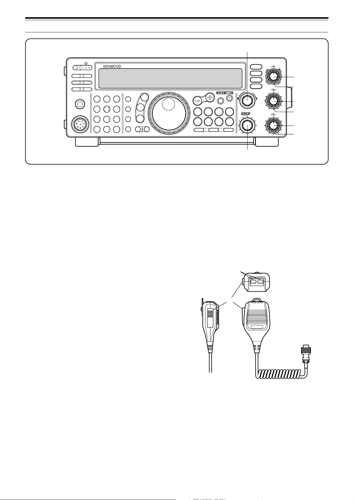
FRONT PANEL
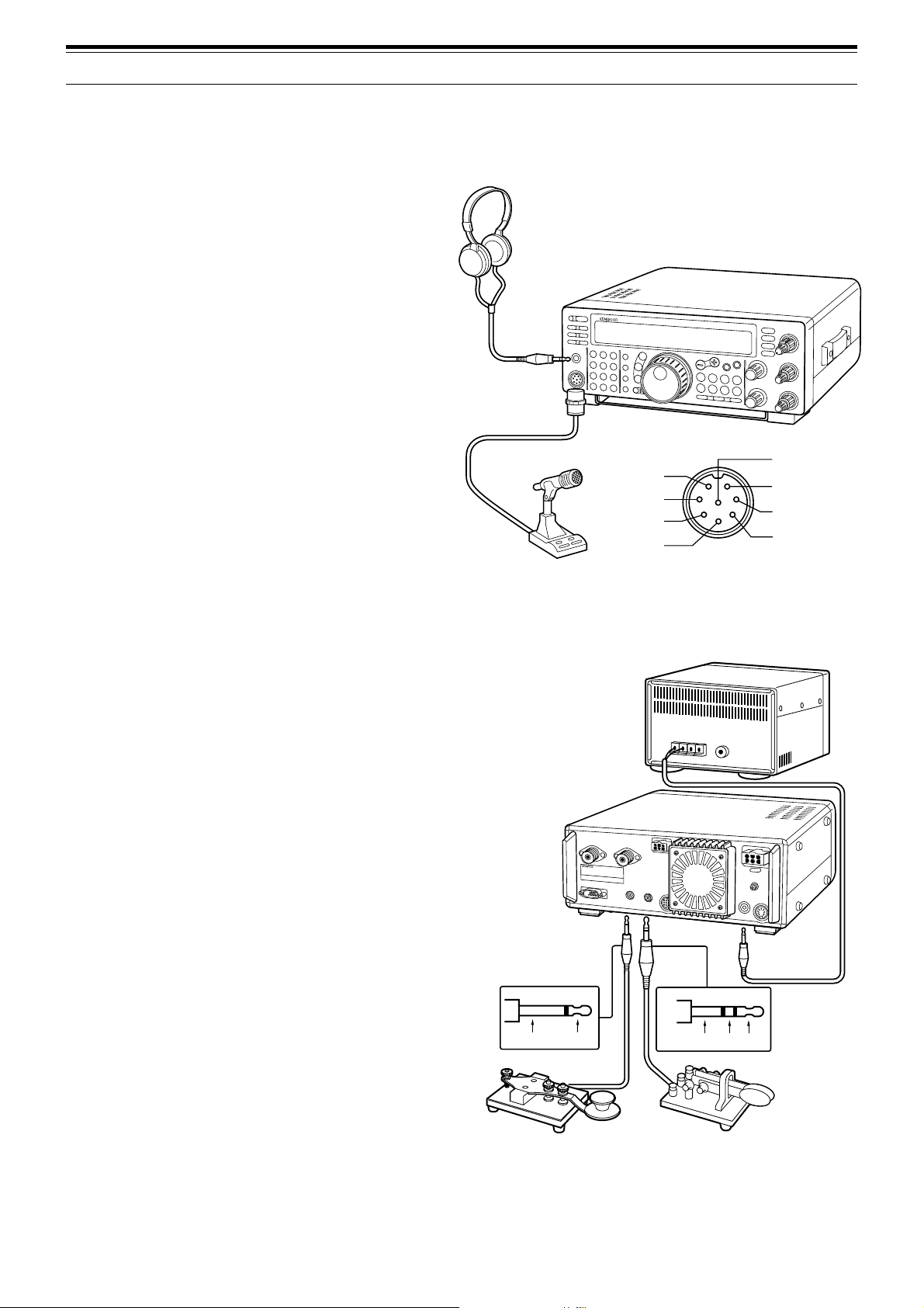
■ Headphones (PHONES)
Use headphones having 4 to 32 Ω impedance. You
can also use stereo headphones. When
headphones are used, no sound is heard from the
internal (or optional external) speaker. Use a 6.0 mm
(1/4") diameter, 2-conductor (mono) or 3-conductor
(stereo) plug.
■ Microphone (MIC)
To communicate in the voice modes, connect to the
MIC connector a microphone having an impedance
between 250 Ω and 600 Ω. Insert the connector
from your microphone fully, then screw the retaining
ring clockwise until snug. Compatible microphones
include the MC-43S, MC-47, MC-60A, MC-80,
MC-85, and MC-90. Do not use the MC-44,
MC-44DM, MC-45, MC-45E, MC-45DM,
MC-45DME, MC-52DM, or MC-53DM microphone.
REAR PANEL
■ External Speaker (EXT SP)
Ensure any external speaker used has an
impedance of 8 Ω. Use a 3.5 mm (1/8") diameter,
2-conductor (mono) plug. When an external speaker
is used, no sound is heard from the internal speaker.
WARNING!
DO NOT CONNECT HEADPHONES TO THIS
JACK. THE HIGH AUDIO OUTPUT AT THIS JACK COULD
DAMAGE YOUR HEARING.
■ Keys and Keyboards for CW Operation
(PADDLE and KEY)
For CW operation using the internal electronic keyer,
connect a keyer paddle to the PADDLE jack. For
CW operation without using the internal electronic
keyer, connect a straight key, semi-automatic key
(bug), electronic keyer, or the CW keyed output from
a Multimode Communications Processor (MCP) to
the KEY jack. The jacks mate with a 6.0 mm (1/4")
3-conductor plug and a 3.5 mm (1/8") 2-conductor
plug respectively. External electronic keyers or
MCPs must use positive keying to be compatible
with this transceiver. Use a shielded cable between
the key and the transceiver.
Note:
Due to the full-featured functionality of the internal
electronic keyer, you may decide it’s unnecessary to connect
both a paddle and another type of key unless you specifically
want to use a keyboard for CW. It’s recommended that you
become familiar with the internal keyer by reading
“ELECTRONIC KEYER” {page 34} before making your decision.
TS-570
Headphones
Microphone
iGND(STBY)
MICq
uGND(MIC)
yNC
t8 V(10 mA max)
PTTw
DOWNe
UPr
MIC connector (Front view)
External speaker
TS-570
• Paddle
• Straight key
• Bug
• Electronic keyer
• MCP CW output
Ground +
Ground Dash
Dot
YOUR FIRST QSO
4
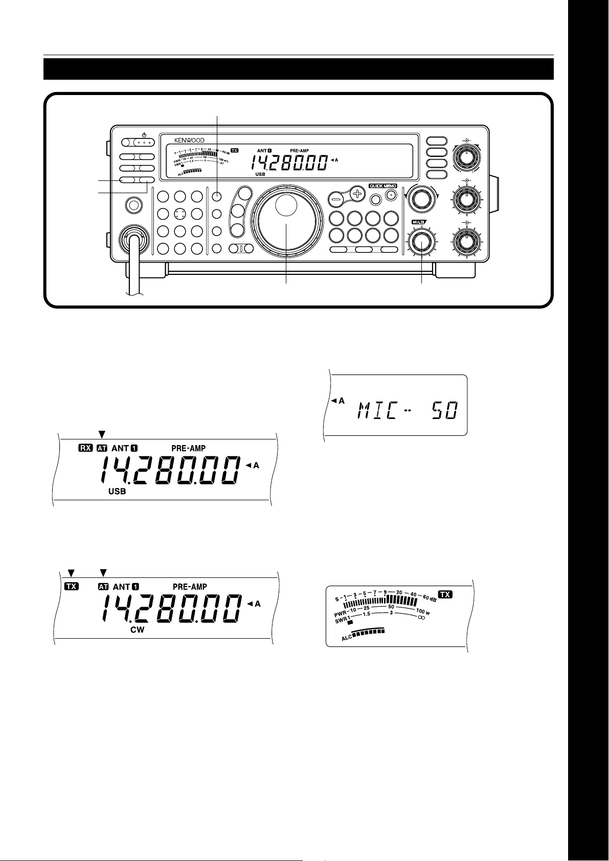
RECEIVING
2 YOUR FIRST QSO
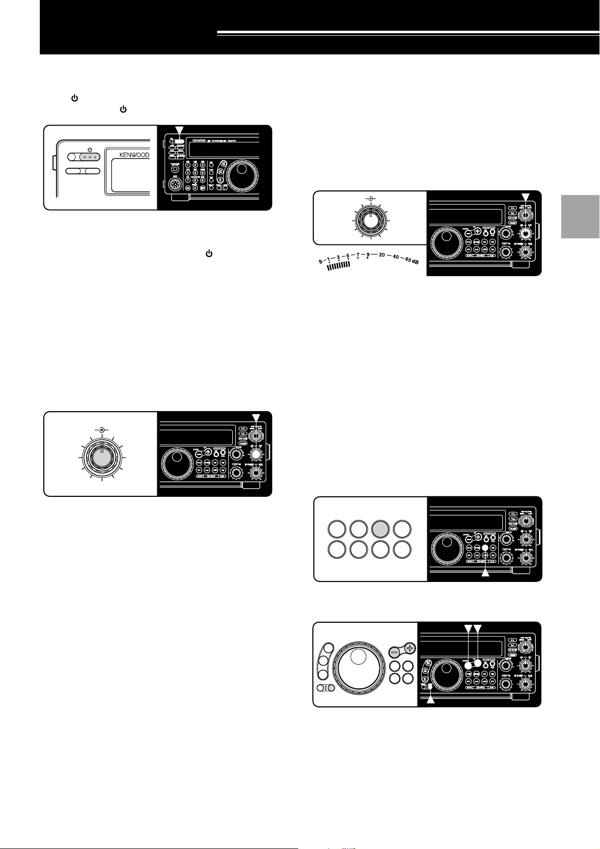
Note:
Only those buttons and controls required to briefly try the
transceiver are explained in this section.
q Set the following as specified:
• AF control: Fully counterclockwise
• RF control: Fully clockwise
• DSP SLOPE (HIGH) control:
Fully clockwise
• DSP SLOPE (LOW) control:
Fully counterclockwise
• IF SHIFT control: Center
• SQL control: Fully counterclockwise
w Switch ON the DC power supply, then press and
hold the [ ] (POWER) switch briefly.
• The transceiver switches ON. Indicators and
frequency digits should appear on the display.
e VFO A should already be selected for receiving
and transmitting, and you should see “tA” on the
display. If not, press the [A/B] button.
r Increase the AF control slowly clockwise until you
hear a suitable level of background noise.
t Select an Amateur band by pressing the [UP] or
[DOWN] button.
y Select an operating mode by pressing the
[LSB/USB] or [CW/FSK] button.
• Press the same button again to toggle to the
second function on the button. For example,
repeatedly pressing the [LSB/USB] button
switches between LSB and USB modes.
u Turn the Tuning control to tune in a station.
• If no stations are heard but you have an
antenna connected, possibly the wrong
antenna connector is selected. Pressing the
[ANT] button toggles between the Antenna 1
and the Antenna 2 connectors.
Since you’ve now installed the TS-570, why not try it? The instructions below are abbreviated. They are intended
only to act as a quick introduction. If you encounter problems or there’s something you don’t understand, you can
read about the subject in more detail later.
• Note that pressing [ ] (POWER) for more
than approximately 2 seconds switches the
transceiver power OFF.
PF
ATT PRE-AMP
VOX PROC
SEND
CH1
MIC
CW
FSK
LSB
USB
FM
AM
AT TUNE
HF TRANSCEIVER TS-570D
PHONES
1
CH2
2
CH3
3
ANT
4
REC
5
FINE
6
NB
7
AGC/TONE
8
REV
9
CLR
F.LOCK
0
ENT
MIC
PWR
KEY
DELAY MENU 1MHz
SPLIT
M/V
DOWN
UP
MR
TF-SET
A=B
SCAN M>VFO M.IN
M.IN
FILTER
CW TUNE
B.C.
N.R.
A/B
CLEAR
RIT
XIT
RIT/XIT
IF SHIFT SQL
CH
46
010
28
AF RF
L
O
W
C
U
T
HIGH
DSP SLOPE
LOW
46
010
28
+–
tw
e
u
y
q
q
qr
q
q
q
5
YOUR FIRST QSO
TRANSMITTING
2 YOUR FIRST QSO
After tuning in a few stations as explained in the
previous section “RECEIVING”, try making a contact.
q Assuming you are already on the correct band
with the correct mode selected (steps 1~7 in
“RECEIVING”), use the Tuning control to tune in
a station or to select an unused frequency.
w Momentarily press the [AT TUNE] button.
•“AT” appears.
e Press and hold the [AT TUNE] button to allow the
built-in antenna tuner to function.
•“AT” blinks and “TX” appears.
•Tuning should be completed in less than
approximately 20 seconds. “AT” stops blinking
and “TX” disappears.
• If tuning is not completed in approximately 20
seconds, error beeps sound. Press
[ATTUNE] to stop the error beeps and to quit
tuning. Check your antenna system before
continuing.
Note:
Tuning will automatically turn off after approximately
60 seconds. In addition, “AT” will disappear and the error beeps
will stop.
r SSB: Press the [MIC] button to activate the
Microphone Gain Setting function.
• “MIC-50” appears.
CW: Skip this step.
t Press the [SEND] button.
• “TX” appears.
y Begin speaking into the microphone or sending
CW with your key.
u SSB: While speaking into the microphone, adjust
the MULTI/CH control so that the ALC meter
reflects according to your voice level.
CW: Skip this step.
i Press the [SEND] button again when you want to
return to receive mode.
o Press the [MIC] button again to quit the
Microphone Gain Setting function.
This completes your introduction to the TS-570, but
there is a great deal more to know. “OPERATING
BASICS” {page 13} and following chapters explain all
functions of the transceiver starting with the most
basic, commonly-used functions.
PF
ATT PRE-AMP
VOX PROC
SEND
CH1
MIC
CW
FSK
LSB
USB
FM
AM
AT TUNE
HF TRANSCEIVER TS-570D
PHONES
1
CH2
2
CH3
3
ANT
4
REC
5
FINE
6
NB
7
AGC/TONE
8
REV
9
CLR
F.LOCK
0
ENT
MIC
PWR
KEY
DELAY MENU 1MHz
SPLIT
M/V
DOWN
UP
MR
TF-SET
A=B
SCAN M>VFO M.IN
M.IN
FILTER
CW TUNE
B.C.
N.R.
A/B
CLEAR
RIT
XIT
RIT/XIT
IF SHIFT SQL
CH
46
010
28
AF RF
L
O
W
C
U
T
HIGH
DSP SLOPE
LOW
46
010
28
+–
we
ti
ro
u
q
6
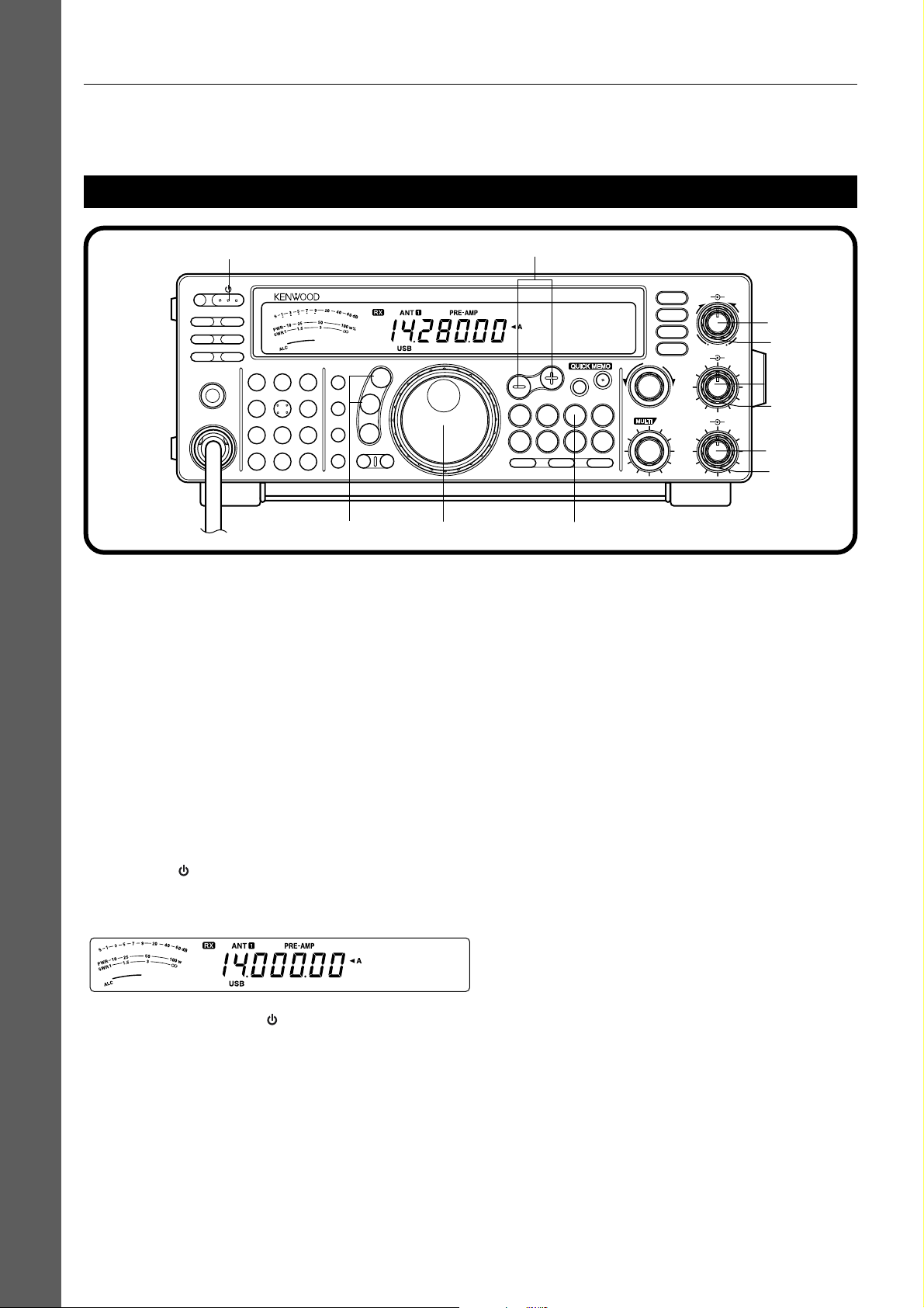
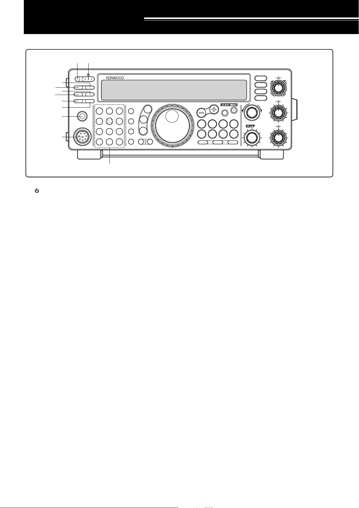
FRONT PANEL
oo
oo
o PHONES jack
Connect headphones to this jack. Inserting a plug into
the jack automatically mutes the audio from the speaker
{page 3}.
!0!0
!0!0
!0 MIC connector
Connect a compatible microphone, then snugly screw
down the connector locking ring {page 3}.
!1!1
!1!1
!1 Multi-purpose keypad
Consists of 10 buttons that are used for inputting
numeric data. Also used for the following functions.
• CH 1, CH 2, CH 3 buttons
Press to select functions associated with the internal
electronic keyer {page 34} and the DRU-3A Digital
Recording Unit {page 53} .
• ANT button
Press to select either Antenna 1 or Antenna 2 that
are connected to their respective antenna
connectors on the rear panel {pages 1, 48}.
• REC button
Press to select the record mode for CW Message
Memory {page 35} or for the optional DRU-3A Digital
Recording Unit {page 53}.
• FINE button
Press to reduce by one-tenth the Tuning control
step size to allow more precise tuning {page 29}.
• NB button
Press to switch ON or OFF the analog Noise Blanker
{page 36}.
• AGC/TONE button
Press to switch the Automatic Gain Control function
between Slow and Fast {page 30}. Also switches
ON or OFF the Subtone {page 24} or CTCSS
function {page 25}.
qq
qq
q (POWER) switch
Press and hold down briefly to switch ON the
transceiver power. Press again to switch OFF the
power {page 13}.
ww
ww
w PF button
A function can be assigned by the user to this
Programmable Function button {page 49}. The default
function is Voice 1 {page 55}.
ee
ee
e PRE-AMP button
Press to switch ON or OFF the receive preamplifier
{page 37}.
rr
rr
r AT T button
Press to switch ON or OFF the receive attenuator
{page37}.
tt
tt
t PROC button
Press to switch ON or OFF the Speech Processor for
transmitting {page 32}.
yy
yy
y VOX button
In voice modes, press to switch ON or OFF the Voice-
Operated Transmit function {page 31} or, in CW mode,
to switch ON or OFF the Break-in function {page 34}.
uu
uu
u AT TUNE button
Use for activating the internal antenna tuner {page 52}
or an external antenna tuner.
ii
ii
i SEND button
Press to switch the transceiver between receive mode
and transmit mode {page 15}.
GETTING ACQUAINTED
PF
ATT PRE-AMP
VOX PROC
SEND
CH1
MIC
CW
FSK
LSB
USB
FM
AM
AT TUNE
HF TRANSCEIVER TS-570D
PHONES
1
CH2
2
CH3
3
ANT
4
REC
5
FINE
6
NB
7
AGC/TONE
8
REV
9
CLR
F.LOCK
0
ENT
MIC
PWR
KEY
DELAY MENU 1MHz
SPLIT
M/V
DOWN
UP
MR
TF-SET
A=B
SCAN M>VFO M.IN
M.IN
FILTER
CW TUNE
B.C.
N.R.
A/B
CLEAR
RIT
XIT
RIT/XIT
IF SHIFT SQL
CH
46
010
28
AF RF
L
O
W
C
U
T
HIGH
DSP SLOPE
LOW
46
010
28
+–
q
w
!0
e
r
t
y
u
i
o
!1
7
3 GETTING ACQUAINTED
• REV button
In CW or FSK mode, press to select either the upper
or lower sideband while receiving {pages 21, 26}.
• CLR button
Press to exit from, abort, or reset various functions.
Also used for erasing memory channels {page 43}
or for locking out memory channels from the scan
list {page 44}.
• F.LOCK button
Press to switch ON or OFF the Frequency Lock
function {page 48}.
• ENT button
Press to enter the desired frequency via the keypad
{page 29}.
!2!2
!2!2
!2 Transmit function buttons
Used in conjunction with the MULTI/CH control to set
various transmit functions.
• MIC button
Used for setting the microphone gain level
{page15}.
• PWR button
Used for setting the transmit output power
{page15}.
• KEY button
Used for setting the internal electronic keyer speed
{page 34}.
• DELAY button
When using the VOX or Break-in function, used for
setting the time delay from transmit mode to receive
mode {pages 31, 34}.
!3!3
!3!3
!3 Mode buttons
Press these buttons to select your operating mode
{page14}.
• LSB/USB button
Press to select lower sideband or upper sideband
mode for voice or digital operation {pages 20, 27}.
• CW/FSK button
Press to select CW or frequency shift keying mode
{pages 21, 26}.
• FM/AM button
Press to select FM or AM mode {page 22}.
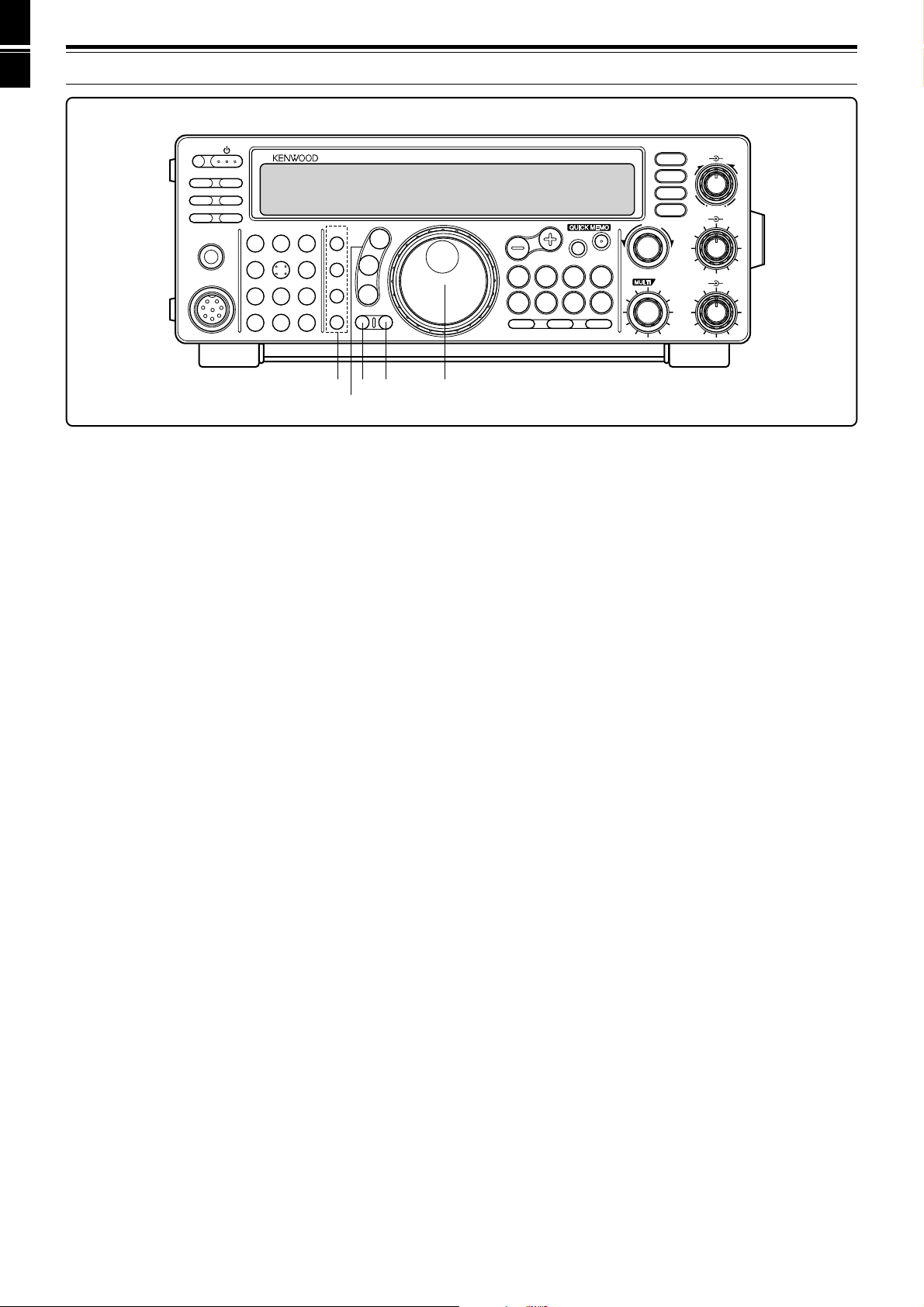
!4!4
!4!4
!4 MENU button
Press to select or cancel the Menu mode that is used for
activating and configuring functions {page 16}.
!5!5
!5!5
!5 1MHz button
Press to switch between the 1 MHz step mode and the
Amateur band mode {page 29}.
!6!6
!6!6
!6 Tuning control
Turn to select the desired frequency {page 14}. Use the
convenient finger-tip cavity for continuous tuning.
The lever behind the control adjusts the control torque
level; turn fully clockwise for light torque or fully
counterclockwise for slightly heavy torque.
PF
ATT PRE-AMP
VOX PROC
SEND
CH1
MIC
CW
FSK
LSB
USB
FM
AM
AT TUNE
HF TRANSCEIVER TS-570D
PHONES
1
CH2
2
CH3
3
ANT
4
REC
5
FINE
6
NB
7
AGC/TONE
8
REV
9
CLR
F.LOCK
0
ENT
MIC
PWR
KEY
DELAY MENU 1MHz
SPLIT
M/V
DOWN
UP
MR
TF-SET
A=B
SCAN M>VFO M.IN
M.IN
FILTER
CW TUNE
B.C.
N.R.
A/B
CLEAR
RIT
XIT
RIT/XIT
IF SHIFT SQL
CH
46
010
28
AF RF
L
O
W
C
U
T
HIGH
DSP SLOPE
LOW
46
010
28
+–
!2
!3
!4
!5
!6
8
3 GETTING ACQUAINTED
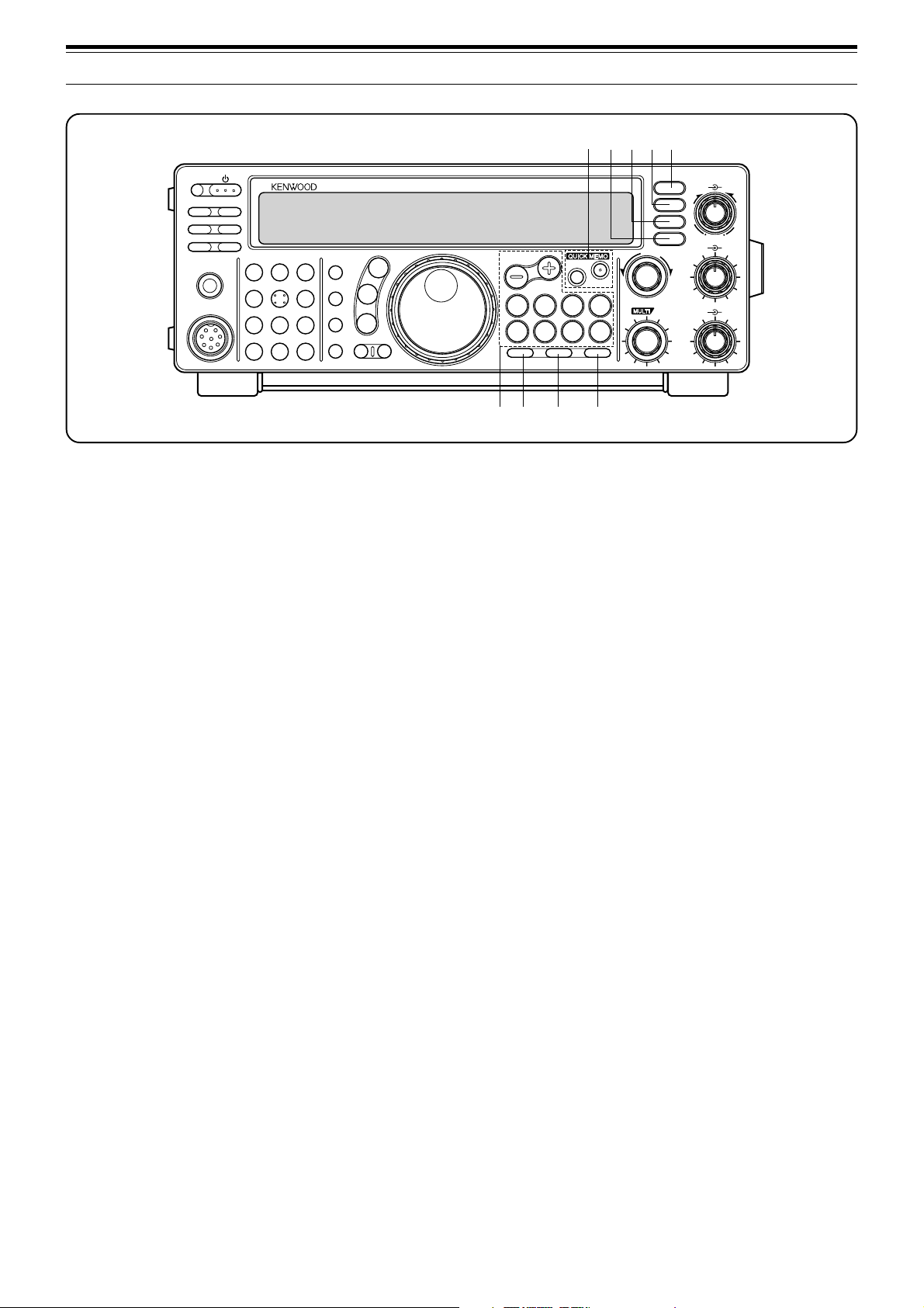
!7!7
!7!7
!7 Frequency control buttons
These buttons control functions related to selecting a
frequency, a VFO, or a memory channel.
• UP/DOWN buttons
Press to step through all Amateur bands
consecutively {page 13} or to step the transceiver
frequency in 1 MHz increments {page 29}. Also
used for making selections from the Menu
{page16}, and to check Start and End frequencies
for the Scan function {page 43}.
• SPLIT button
Press to use split-frequency operation which allows
a different transmit frequency and receive frequency
{page 23}.
• M/V button
Press to select either Memory or VFO mode
{page40}.
• TF-SET button
While operating split-frequency, press to monitor or
change your transmit frequency {page 23}.
• A=B button
Press to copy the data in the currently selected VFO
over to the other VFO {page 30}.
• A/B button
Press to select either VFO A or VFO B {page 13}.
Also, in menu mode, press to select either Menu A
or Menu B {page 16}.
• CLEAR button
Press to reset the RIT/XIT frequency offset to zero
{pages 30, 32}.
• RIT button
Press to switch ON or OFF the Receive Incremental
Tuning function {page 30}.
• XIT button
Press to switch ON or OFF the Transmit
Incremental Tuning function {page 32}.
!8!8
!8!8
!8 SCAN button
Press to start and stop Scan functions {pages 46, 47}.
!9!9
!9!9
!9 M>VFO button
Press to transfer data from a memory channel to a VFO
{page 42}.
@0@0
@0@0
@0 M.IN button
Writes data into a memory channel {page 39} or selects
Memory Scroll mode {page 41}.
@1@1
@1@1
@1 Quick Memory buttons
Controls the Quick Memory function {page 44}.
• M.IN button
Press to write data into Quick Memory {page 44}.
• MR button
Press to recall data from Quick Memory {page 45}.
@2@2
@2@2
@2 FILTER button
Press to select the receive filter bandwidth in SSB, CW,
FSK, or AM mode {pages 36, 38}, or press to select
either narrow-band or wide-band transmit deviation in
FM mode {page 22}.
Note:
Selecting the narrow filter bandwidth in SSB mode requires
the optional YK-88SN-1 filter {page 36}.
@3@3
@3@3
@3 CW TUNE button
Press to activate the automatic zero-beat function for
CW mode {page 21}.
@4@4
@4@4
@4 B.C. button
Press to switch ON or OFF the DSP Beat Cancel
function {page 38}.
@5@5
@5@5
@5 N.R. button
Press to toggle between Noise Reduction 1, Noise
Reduction 2, and OFF {page 38}.
PF
ATT PRE-AMP
VOX PROC
SEND
CH1
MIC
CW
FSK
LSB
USB
FM
AM
AT TUNE
HF TRANSCEIVER TS-570D
PHONES
1
CH2
2
CH3
3
ANT
4
REC
5
FINE
6
NB
7
AGC/TONE
8
REV
9
CLR
F.LOCK
0
ENT
MIC
PWR
KEY
DELAY MENU 1MHz
SPLIT
M/V
DOWN
UP
MR
TF-SET
A=B
SCAN M>VFO M.IN
M.IN
FILTER
CW TUNE
B.C.
N.R.
A/B
CLEAR
RIT
XIT
RIT/XIT
IF SHIFT SQL
CH
46
010
28
AF RF
L
O
W
C
U
T
HIGH
DSP SLOPE
LOW
46
010
28
+–
!7 ! 8 !9 @0
@1
@2
@3@4@5
9
3 GETTING ACQUAINTED
@6@6
@6@6
@6 DSP SLOPE (HIGH) control
In SSB or AM mode, turn to change the high cut-off
frequency of the receive pass band. Use the control to
improve readability of the desired signal when higher
frequency interference is present {page 37}.
@7@7
@7@7
@7 DSP SLOPE (LOW) control
In SSB or AM mode, turn to change the low cut-off
frequency of the receive pass band. Use the control to
improve readability of the desired signal when lower
frequency interference is present {page 37}.
@8@8
@8@8
@8 RIT/XIT control
After switching ON the RIT or XIT function, turn to
select the desired frequency offset {pages 30, 32}.
@9@9
@9@9
@9 AF control
Turn to adjust the audio frequency gain {page 13}.
#0#0
#0#0
#0 RF control
Turn to adjust the radio frequency gain {page 13}.
#1#1
#1#1
#1 IF SHIFT control
Turn to slide the receive pass band either lower or
higher in frequency when interference is present
{page36}.
#2#2
#2#2
#2 SQL control
Used for muting (“squelching”) the speaker output when
no receive signal is present {page 14}.
#3#3
#3#3
#3 MULTI/CH control
In VFO mode, turn to step the operating frequency up
or down {page 29}. In memory channel mode, turn to
select a memory channel {page 40}. Also used for
selecting Menu numbers when accessing the Menu
mode {page 16}, and as a selector to choose settings
for various functions activated by front panel buttons.
MICROPHONE
qq
qq
q UP/DWN buttons
Use these buttons to step up or down the VFO
frequency, memory channels, or Menu selections.
Press and hold down to continuously change the
settings.
ww
ww
w PTT (Push-to-Talk) switch
The transceiver is placed in transmit mode when this
non-locking switch is held down. Releasing the switch
returns the transceiver to receive mode.
PTT
DWN UP
q
w
PF
ATT PRE-AMP
VOX PROC
SEND
CH1
MIC
CW
FSK
LSB
USB
FM
AM
AT TUNE
HF TRANSCEIVER TS-570D
PHONES
1
CH2
2
CH3
3
ANT
4
REC
5
FINE
6
NB
7
AGC/TONE
8
REV
9
CLR
F.LOCK
0
ENT
MIC
PWR
KEY
DELAY MENU 1MHz
SPLIT
M/V
DOWN
UP
MR
TF-SET
A=B
SCAN M>VFO M.IN
M.IN
FILTER
CW TUNE
B.C.
N.R.
A/B
CLEAR
RIT
XIT
RIT/XIT
IF SHIFT SQL
CH
46
010
28
AF RF
L
O
W
C
U
T
HIGH
DSP SLOPE
LOW
46
010
28
+–
@6
@7
#0
@9
#1
#2
#3
@8
10
3 GETTING ACQUAINTED
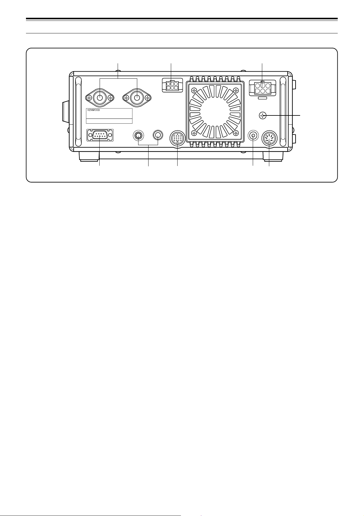
REAR PANEL
qq
qq
q ANT 1 and ANT 2 connectors
Connect the feed lines from your antennas to these
connectors. Refer to pages 1 and 48 for details.
ww
ww
w AT connector
Mates with the connector on the cable supplied with the
external antenna tuner. Refer to the instruction manual
supplied with this tuner for more information.
ee
ee
e DC 13.8 V power input connector
Connect a 13.8 V DC power source {page 2}. Use the
supplied cable with a regulated DC power supply.
rr
rr
r GND post
Connect a heavy gauge wire or copper strap between
the ground post and the nearest earth ground {page 2}.
tt
tt
t COM connector
Mates with a 9-pin female RS-232C connector for
connecting a computer via one of its serial
communication ports {page 60}. Also used with the
Quick Data Transfer function {page 60}.
yy
yy
y KEY and PADDLE jacks
The PADDLE jack mates with a 6.0 mm (1/4")
3-conductor plug for connecting a keyer paddle to the
internal electronic keyer. The KEY jack mates with a
3.5 mm (1/8") 2-conductor plug for connecting an
external key for CW operation. Read “Keys and
Keyboards for CW Operation” {page 3} before
connecting to these jacks.
uu
uu
u ACC 2 connector
Mates with a 13-pin male DIN connector for connecting
various accessory equipment {pages 61, 62}.
ii
ii
i EXT SP jack
Mates with a 3.5 mm (1/8"), 2-conductor (mono) plug for
connecting an external speaker {page 3}. Connecting
an external speaker cuts off the audio automatically to
the internal speaker.
oo
oo
o REMOTE connector
Mates with a 7-pin male DIN connector for connecting a
linear amplifier {page 61}.
European versions only:
Before connecting to the
ACC 2
and
COM
connectors, remove the protective covers.
ANT 2
AT
DC 13.8V
GND
EXT.SP
8Ω
REMOTE
ANT 1
KEY
COM
PADDLE ACC 2
o
w
e
r
t
y
u
i
q
11
3 GETTING ACQUAINTED
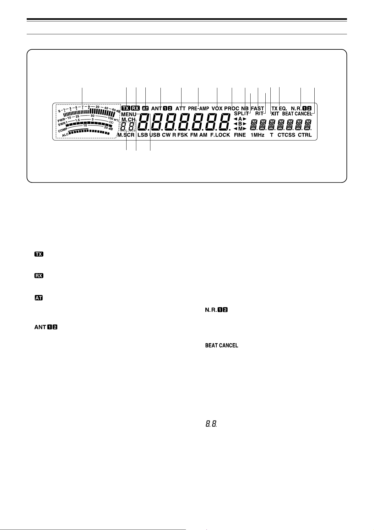
DISPLAY
!2!2
!2!2
!2 FAST
Appears when a fast time constant is selected for the
Automatic Gain Control function {page 30}.
!3!3
!3!3
!3 RIT
Appears when Receive Incremental Tuning is ON
{page30}.
!4!4
!4!4
!4 XIT
Appears when Transmit Incremental Tuning is ON
{page 32}.
!5!5
!5!5
!5 TX EQ.
Appears when the TX Equalizer function is ON
{page33}.
!6!6
!6!6
!6
Either “N.R. 1” or “N.R. 2” appears depending on
whether Noise Reduction 1 or Noise Reduction 2 is
selected {page 38}.
!7!7
!7!7
!7
Appears when Beat Cancel is ON {page 38}.
!8!8
!8!8
!8 MENU
Appears while Menu mode is being accessed
{page16}.
!9!9
!9!9
!9 M.CH
Appears while Memory Recall or Memory Scroll is
being used {page 40}.
@0@0
@0@0
@0
Shows 2-digit information such as a menu number or a
memory channel number.
qq
qq
q METER
While receiving, serves as an S-meter to measure and
display the received signal strength. While transmitting,
serves as a calibrated power meter plus an ALC meter,
an SWR meter, or a Speech Processor compression
meter. The Peak Hold function holds each reading for
about 2.5 seconds.
ww
ww
w
Appears while the transceiver is in the transmit mode.
ee
ee
e
Appears while the squelch is open in the receive mode.
rr
rr
r
Appears while the internal antenna tuner {page 52} or an
external antenna tuner is in-line.
tt
tt
t
Either “ANT 1” or “ANT 2” appears depending on
whether the Antenna 1 connector or the Antenna 2
connector is selected {page 48}.
yy
yy
y ATT
Appears when the receive attenuator is ON {page 37}.
uu
uu
u PRE -AMP
Appears when the receive preamplifier is ON {page 37}.
ii
ii
i VOX
Appears when the Voice-Operated Transmit function is
ON {page 31}. For CW operation, appears when the
Break-in function is ON {page 34}.
oo
oo
o PROC
Appears when Speech Processor is ON {page 32}.
!0!0
!0!0
!0 NB
Appears when Noise Blanker is ON {page 36}.
!1!1
!1!1
!1 SPLIT
Appears when the transmit frequency differs from the
receive frequency {page 23}.
o
qw
e
rt y
u
i
!9
!0
!2
!3
!4
!5
!6 !7
!8@0
!1
12
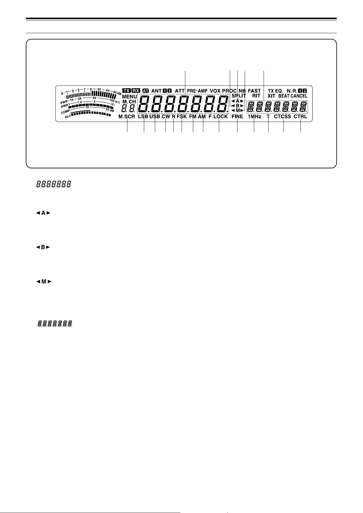
3 GETTING ACQUAINTED
#0#0
#0#0
#0 R
Appears while the sideband is being reversed for CW
{page 21}. Also appears while the mark and space
frequency relationship is being reversed for FSK
{page26}.
#1#1
#1#1
#1 FSK
Appears when in Frequency Shift Keying mode
{page26} or when you select one of the digital operation
filters via Menu No. 32 in SSB mode {page27}.
#2#2
#2#2
#2 FM
Appears when in FM mode {page 14}.
#3#3
#3#3
#3 AM
Appears when in AM mode {page 14}.
#4#4
#4#4
#4 F.LOCK
Appears when the Frequency Lock function is ON
{page48}.
#5#5
#5#5
#5 FINE
Appears when the Fine function is ON {page 29}.
#6#6
#6#6
#6 1MHz
Appears when the 1 MHz Step function is ON {page29}.
#7#7
#7#7
#7 T
Appears when the Subtone function is ON {page 24}.
#8#8
#8#8
#8 CTCSS
Appears when CTCSS is ON {page 25}.
#9#9
#9#9
#9 CTRL
Appears while Quick Data Transfer {page 50} or
Computer Control {page 51} is being used.
@1@1
@1@1
@1
Shows the current operating frequency. Also shows
Menu selections while in Menu mode.
@2@2
@2@2
@2
“tA” or “As” appears while VFO A is being selected
{page13}. “A” appears while Menu A is being
accessed {page16}.
@3@3
@3@3
@3
“tB” or “Bs” appears while VFO B is being selected
{page13}. “B” appears while Menu B is being
accessed {page16}.
@4@4
@4@4
@4
“tM” or “Ms” appears while a simplex memory
channel is being selected {page 40}. “tMs” appears
while a split-frequency memory channel is being
selected {page 40}.
@5@5
@5@5
@5
Shows menu information while Menu A or B is being
accessed. Also shows the transmit frequency during
split-frequency operation, and the RIT/XIT offset
frequency when these functions are ON.
@6@6
@6@6
@6 M.SCR
Appears while Memory Scroll is being used {page 41}.
@7@7
@7@7
@7 LSB
Appears when in Lower Sideband mode {page 14}.
@8@8
@8@8
@8 USB
Appears when in Upper Sideband mode {page 14}.
@9@9
@9@9
@9 CW
Appears when in CW mode {page 14}.
#3
@6
@7
@8
@9 #0
#1
#2
@3
#4
#5
#7
#8
#6
@2
@1
#9
@4 @5
1
2
3
4
5
6
7
8
9
10
11
12
13
14
15
16
13
OPERATING BASICS
SWITCHING POWER ON/OFF
Switch ON the DC power supply, then press and hold
down [
] (POWER) until “HELLO” appears on the
display. Release [ ] (POWER) when you see “HELLO”.
• After the “HELLO” message, the frequency and
other indicators appear.
To switch OFF the transceiver, press [ ] (POWER).
• After the transceiver has been switched ON, it can
then be switched OFF or ON by using only the
power switch on the DC power supply.
ADJUSTING VOLUME
AUDIO FREQUENCY (AF) GAIN
Turn the AF control clockwise to increase the audio
level and counterclockwise to decrease the level.
Note:
The position of the
AF
control does not affect the volume of
“beeps” caused by pressing buttons nor the CW transmit sidetone.
Also, the audio level for Packet operation is independent of the
AF
control setting.
RADIO FREQUENCY (RF) GAIN
Usually, set the RF control fully clockwise. If you are
having trouble hearing the desired signal due to
excessive atmospheric noise or interference from other
stations, it may help to reduce the RF gain.
To do this, take note of the peak S-meter reading of the
desired signal. Turn the RF control counterclockwise
until the S-meter reads the peak value that you noted.
Signals that are weaker than this level will be
attenuated. Reception of the station will be easier.
Depending on the type and gain of your antenna, and
the condition of the band, you may prefer leaving the RF
control turned counterclockwise by some amount
instead of turning it fully clockwise. When in FM mode,
always set the RF gain control fully clockwise.
SELECTING VFO A OR VFO B
VFO A and VFO B are modes that allow any desired
frequency to be selected within the frequency range of
the transceiver. VFO A and VFO B function
independently so that different or the same frequencies
can be selected for each VFO.
Press [A/B] to toggle between VFO A and VFO B.
•“tA” or “tB” appears and shows which VFO is
selected.
SELECTING A BAND
1 If “1MHz” is visible on the display, first press [1MHz]
to exit from the 1MHz Step mode.
• “1MHz” should disappear.
2 Press [UP] or [DOWN].
• Holding down either button consecutively steps
the transceiver to each band.
QUICK MEMO
AF RF
46
010
2
8
QUICK MEMO
CW
FSK
LSB
USB
FM
AM
MENU 1MHz
SPLIT
M/V
DOWN
UP
TF-SET
A=B
QUICK MEMO
SPLIT
M/V
TF-SET
A=B
A/B
CLEAR
RIT
XIT
PF
ATT PRE-AMP
QUICK MEMO
AF RF
46
010
2
8
1
2
3
4
5
6
7
8
9
10
11
12
13
14
15
16
14
4 OPERATING BASICS
SELECTING A FREQUENCY
There are two simple methods to select a frequency.
A Manual Tuning
Turn the Tuning control or press Mic [UP]/[DWN] to
select the exact frequency.
B Direct Frequency Entry (Keypad)
Press [ENT], then directly enter the desired
frequency using the numeric keypad. For details,
refer to “Direct Frequency Entry” {page 29}.
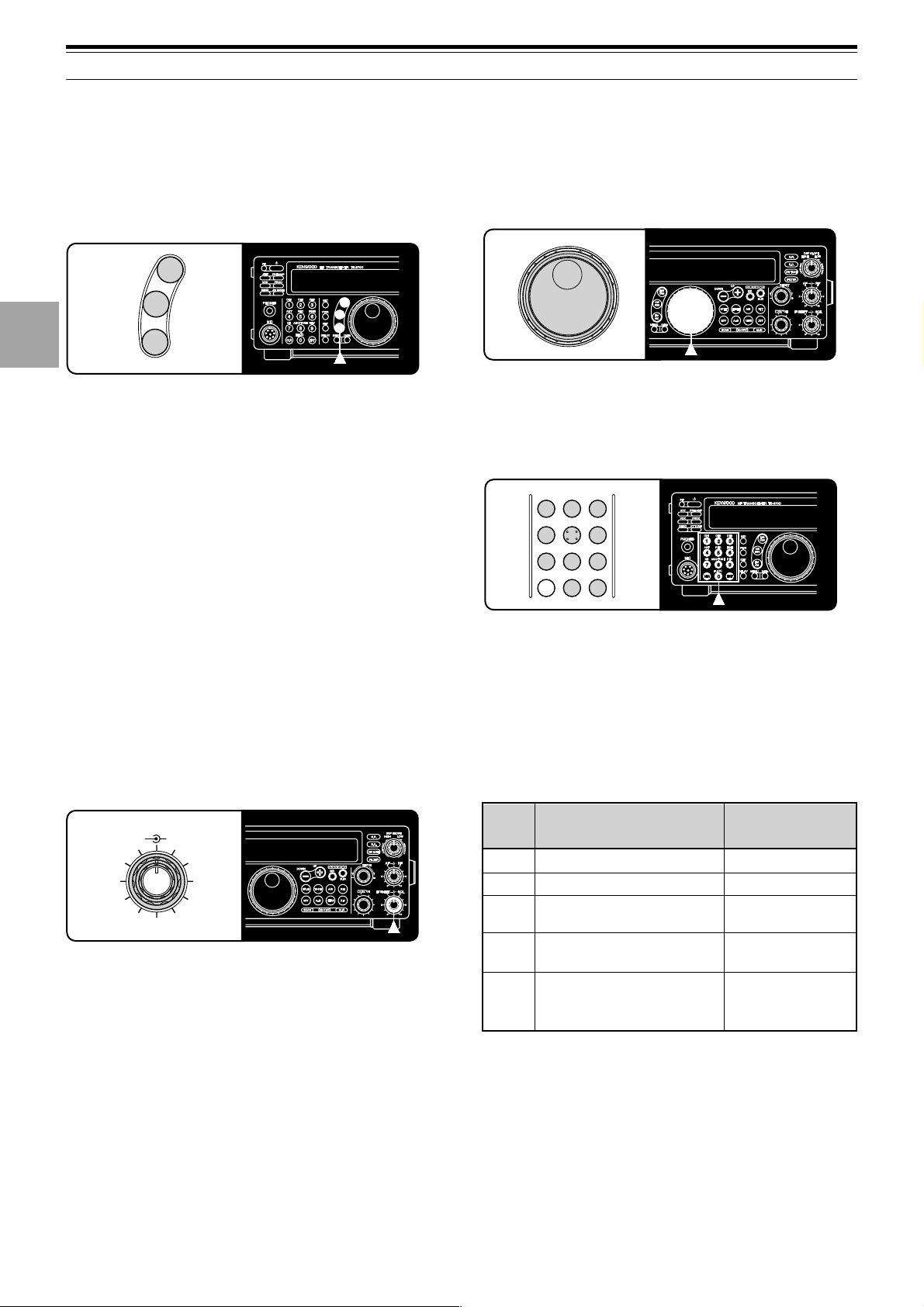
FRONT PANEL METER
The multifunction meter measures the parameters in the
table below. The appropriate meters automatically
become functional according to which state the
transceiver is in. Peak readings for the S-meter, ALC,
SWR, COMP, and PWR functions are held for a brief
moment.
QUICK MEMO
IF SHIFT SQL
46
010
2
8
QUICK MEMO
S
PWR
ALC
SWR
COMP
Received signal strength
Transmit output power
Automatic level control
status
Antenna system standing
wave ratio
Speech compression level
when using the Speech
Processor {page 32}
Receive
Transmit
Transmit
Transmit
Transmit plus
SSB/AM/FM mode
plus [PROC] ON
Display
Scale
Functional State
Note:
◆
The COMP meter functions only when the Speech Processor is
ON while using SSB, FM, or AM mode. When the COMP meter
appears, the SWR meter disappears.
◆
Peak Hold readings cannot be deactivated on this transceiver.
SELECTING A MODE
Depending on which operating mode you want to select,
press the [LSB/USB], [CW/FSK], or [FM/AM] button.
The second function on each button is accessed by
again pressing the same button. For example,
repeatedly pressing [LSB/USB] toggles between LSB
and USB modes.
In SSB mode, the transceiver automatically selects LSB
for frequencies lower than 9.5 MHz, and selects USB for
9.5 MHz or higher frequencies if the Tuning control, the
MULTI/CH control, or Mic [UP]/[DWN] is used to cross
the frequency of 9.5 MHz. This is also true if using the
front panel [UP] or [DOWN] button when the 1 MHz
Step mode is used.
ADJUSTING SQUELCH
The purpose of squelch is to silence audio output from
the speaker when no signal is present. When squelch
is set correctly, you will hear sound only while a station
is actually being received. The point at which ambient
noise on a frequency just disappears, called the squelch
threshold, depends on the frequency.
Turn the SQL control clockwise to just eliminate the
background noise when no signal is present. Many
operators prefer leaving the squelch control fully
counterclockwise unless operating full-carrier modes
such as FM or AM.
CW
FSK
LSB
USB
FM
AM
CH1
1
CH2
2
CH3
3
ANT
4
REC
5
FINE
6
NB
7
AGC/TONE
8
REV
9
CLR
F.LOCK
0
ENT
1
2
3
4
5
6
7
8
9
10
11
12
13
14
15
16
15
4 OPERATING BASICS
TRANSMITTING
Methods for transmitting include the following:
• Press [SEND].
• Press and hold down Mic [PTT].
• Connect a key or keyer paddle, select the CW mode,
press [VOX] to switch ON the Break-in function, and
close the key or keyer paddle.
For a detailed explanation on transmitting, refer to
sections in “BASIC COMMUNICATING” beginning on
page 20.
Note:
When CW, FSK, or AM is selected, the transmit carrier level is
automatically adjusted according to the selected mode.
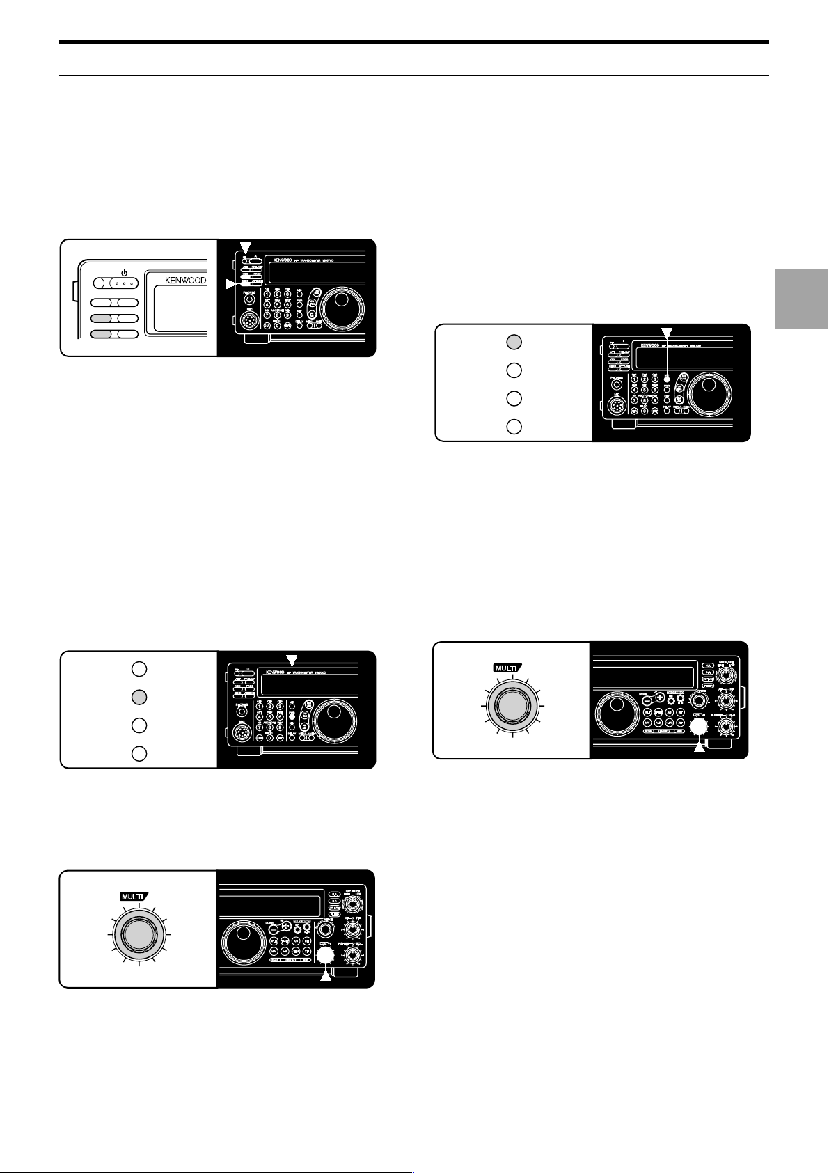
SELECTING TRANSMIT POWER
It’s wise, and required by law, to select the lowest
transmit power that allows reliable communication.
Reducing power lowers the risk of interfering with others
on the band. On this transceiver, it is possible to
change output power while transmitting.
1 Press [PWR].
• The current transmit power appears.
2 Turn the MULTI/CH control counterclockwise to
reduce power and clockwise to increase power.
• The displayed transmit power changes.
• SSB/CW/FSK/FM: Transmit power can be
changed from 5 W to 100 W in steps of 5 W.
• AM: Transmit power can be changed from 5 W to
25 W in steps of 5 W.
3 Press [PWR] again to complete the setting.
Note:
The transmit power can be separately selected for the AM
mode independent of the other modes.
MICROPHONE GAIN
The microphone gain is finely adjustable in the SSB or
AM mode. A different level can be selected between
when the Speech Processor {page 32} is ON and when
the Speech Processor is OFF.
1 Press [MIC].
• The current microphone gain level appears. The
default is 50.
2 Press [SEND] or press and hold Mic [PTT].
• “TX” appears.
3 SSB: While speaking into the microphone, adjust
the MULTI/CH control so that the ALC meter reflects
according to your voice level.
AM: While speaking into the microphone, adjust the
MULTI/CH control so that the calibrated power meter
slightly reflects according to your voice level.
4 Press [SEND] again or release Mic [PTT].
• “TX” disappears.
5 Press [MIC] again.
For the FM mode, set the microphone gain by
accessing Menu No. 17 {page 17} and selecting either
“L” (low) or “H” (high).
Note:
◆
When using the optional MC-90 microphone in FM mode, select
high microphone gain. The microphone sensitivity is low in FM
mode and this may cause insufficient modulation.
◆
When using a microphone that has an amplifier, be careful that
the output of the amplifier is not too large.
QUICK MEMO
CH
QUICK MEMO
CH
PF
ATT PRE-AMP
VOX PROC
SEND AT TUNE
MIC
PWR
KEY
DELAY
MIC
PWR
KEY
DELAY

16
MENU SETUP
WHAT IS A MENU?
Many functions on this transceiver are selected or
configured via a software-controlled Menu instead of
physical controls on the transceiver. Once familiar with
the Menu system, you will appreciate the versatility it
offers. No longer is the number and complexity of
features restricted by the physical controls and
switches on the front panel.
MENU A/ MENU B
The transceiver has two menus. These menus are
called MenuA and MenuB. The menus contain
identical functions; however, each menu can be
configured independently.
For example, you may enjoy two different kinds of
operating activities but you like to configure the
transceiver differently for each activity. MenuA could
be configured with one set of transmit signal
characteristics, DSP settings, programmable buttons,
frequency steps, etc. MenuB could be configured
completely differently. By switching from MenuA to
MenuB, you could instantly change Menu
configuration and button assignment to suit your
current operating style. Or, two operators may share a
single transceiver. By dedicating one Menu per
operator, each would always enjoy the best
configuration.
Note:
The COM communication parameter setting in Menu No. 35
is shared by Menu A and Menu B.
MENU ACCESS
The following procedure explains how to check or
change any of the Menu items.
1 Press [MENU].
• “MENU” appears.
2 Press [A/B] to toggle Menu A or Menu B.
• “A” or “B” appears to show which Menu is
selected.
3 Turn the MULTI/CH control to select the desired
Menu No.
• Each time you change the Menu No. , you will
see a scrolling message that briefly describes the
current Menu No.
4 Press [UP], [DOWN], Mic [UP], or Mic [DWN] to
change the current selection for this Menu item.
5 Press [MENU] or [CLR] to exit Menu mode.

17
5 MENU SETUP
MENU CONFIGURATION
00
01
02
03
04
05
06
07
08
09
10
11
12
13
14
15
16
17
18
19
20
21
22
23
24
25
Page
Ref.
Operator
Interface
Encoder
Memory
Channel
Scan
Antenna Tuner
DSP
TX
CW
DRU
Display brightness
d1: maximum, d4: minimum
Beep output level
1: minimum, 9: maximum
Frequency step size for the [UP]/[DOWN]
buttons in the 1 MHz step mode
Frequency step size for the MULTI/CH control
for SSB, CW, FSK, or AM mode
Frequency step size for the MULTI/CH control
for FM mode
Rounds off VFO frequencies changed by using
the MULTI/CH control
Frequency step size for the MULTI/CH control
for AM mode in the AM broadcast band
Memory-VFO split operation
Tunable (ON) or fixed (OFF) memory channel
frequencies
Program scan hold
Scan resume method
Antenna tuner operation while receiving signals
Time constant for the noise reduction 2 function
TX filter bandwidth for SSB or AM mode
TX equalizer
OFF: flat, Hb: high boost, FP: formant pass,
bb: bass boost, c: conventional
Speech processor compression level
VOX gain
0: minimum, 9: maximum
Microphone gain for FM mode
L: low, H: high
Subaudible tone frequency for FM mode
Type of subaudible tone for FM mode
B: burst, C: continuous
CW RX pitch/ TX sidetone frequency
TX sidetone volume
Semi-automatic key (“Bug”) function
Playback repeat
Interval between repeated playbacks
Playback volume
1: minimum, 9: maximum
Menu
No.
Function
Selections
Group
Default
49
49
29
29
29
29
29
41
41
46
47
52
38
33
33
32
31
22
25
25
21
21
35
35, 53
54
54
OFF/ d4/ d3/ d2/ d1
OFF, 1 to 9
100/ 500/ 1000 kHz
1/ 5/ 10 kHz
1/ 5/ 10/ 12.5/
20/ 25 kHz
ON/ OFF
9 kHz/ 10 kHz
ON/ OFF
ON/ OFF
ON/ OFF
Time-operated/
Carrier-operated
ON/ OFF
7.5/ 20 ms
2.4/ 2.0 kHz
OFF/ Hb/ FP/ bb/ c
(U: not currently
available)
0 to 25 dB in
steps of 5 dB
0 to 9
L/ H
See page reference
B/ C
400 to 1000 Hz in
steps of 50 Hz
OFF, 1 to 9
ON/ OFF
ON/ OFF
0 to 60 sec
OFF, 1 to 9
d2
4
1000 kHz
10 kHz
10 kHz
ON
See page
reference
OFF
OFF
OFF
Time-
operated
OFF
20 ms
2.4 kHz
OFF
10 dB
4
L
88.5 Hz
See page
reference
800 Hz
5
OFF
OFF
10 sec
4

18
26
27
28
29
30
31
32
33
34
35
Page
Ref.
Menu
No.
Function
Selections
Group
Default
34
34
35
26
26
26
27
27
27
51
CW Auto weighting
CW Auto weighting reversed
Keying priority over playback
FSK shift
Key-down polarity for FSK mode
Tone frequencies for FSK mode
2125: 2125 Hz mark, 1275: 1275 Hz mark
Filter bandwidth for digital operation
(SSB and FM modes only)
AF input level for digital operation
(excluding CW and FSK modes)
0: minimum, 2: maximum
AF output level for digital operation
0: minimum, 9: maximum
Communication parameters for COM connector
ON/ OFF
ON/ OFF
ON/ OFF
170/ 200/ 425/ 850 Hz
ON (space)/ OFF (mark)
2125/ 1275 Hz
OFF/ 1200 bps/
300 bps/ PSK
0/ 1/ 2
0 to 9
CW
Digital
Operation
Computer
Interface
Data Transfer
TX
Transverter
PF
RX
ON
OFF
OFF
170 Hz
OFF
2125 Hz
OFF
2
4
96-1
Note: To reliably use the
38400 or 57600 bps transfer
rates, the serial port of your
computer must support these
high-speed communications
parameters.
1200
2400
4800
4800
9600
19200
38400
57600
Data transfer enable
Method of receiving transferred data
ON: Transfer to VFO
OFF: Transfer to quick memory
TX inhibit
Linear amplifier control relay
Enables/disables the 50, 144, or 430 MHz
transverter function.
Programs the [PF] button on the front panel.
Programs the Mic [PF1] button.
Programs the Mic [PF2] button.
Programs the Mic [PF3] button.
Programs the Mic [PF4] button.
IF filter bandwidth
36
37
38
39
40
41
42
43
44
45
46
12-1
24-1
48-1
48-2
96-1
192-1
384-1
576-1
1
1
1
2
1
1
1
1
Setting Transfer Rate (bps) Stop Bits
50
50
33
61
51
49
49
49
49
49
36
ON/ OFF
ON/ OFF
ON/ OFF
ON/ OFF
OFF/ 50/ 144/ 430 MHz
See page reference
See page reference
See page reference
See page reference
See page reference
OFF/
1800/ 500/ 270 Hz
12-1/ 24-1/ 48-1/ 48-2/
96-1/ 192-1/ 384-1/
576-1
OFF
OFF
OFF
OFF
OFF
51
(Voice 1)
64
([A/B])
62
([SPLIT])
65
([M/V])
50
(Monitor)
OFF
5 MENU SETUP
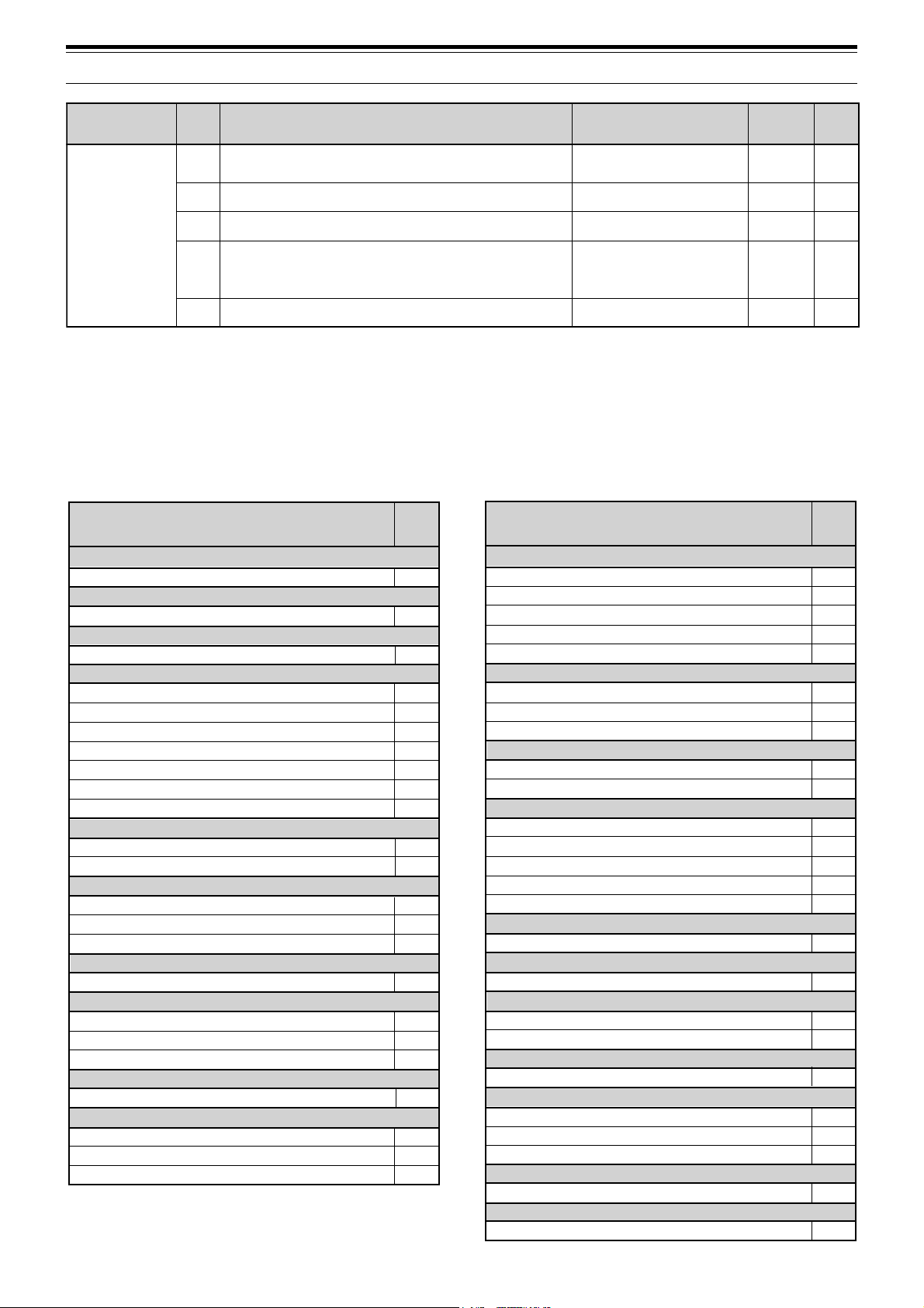
19
5 MENU SETUP
puorG
uneM
.oN
noitcnuF snoitceleS tluafeD
egaP
.feR
decnahnE
74
emulovrotinomlangis-dettimsnarT
mumixam:9,muminim:1
9ot1,FFOFFO33
84TIRhtiwtaeb-orezotuAFFO/NOFFO12
94egnahcthgiew-dekcolreyeK1:0.4ot1:5.21:0.353
05
rezilauqeXR
,ssaptnamrof:PF,tsoobhgih:bH,talf:FFO
lanoitnevnoc:c,tsoobssab:bb
c/bb/PF/bH/FFO
yltnerructon:U(
)elbaliava
FFO03
15egnahclevel1noitcuderesioN9ot1,otuAotuA83
Function
Menu
No.
AMPLIFIER
Linear amplifier relay
ANTENNA TUNER (AT)
RX enable/ disable
BEEP FUNCTIONS
Beep level
CW
Auto weighting
Auto weighting reversed
Keying priority over playback
RX pitch
Semi-automatic key (“Bug”) function
TX sidetone frequency
TX sidetone volume
DATA TRANSFER
Transfer enable
Transfer method
DIGITAL OPERATION
AF input (MCP/TNC TX)
AF output (MCP/TNC RX)
Filter bandwidth
DISPLAY
Brightness
DRU-3A DIGITAL RECORDING SYSTEM (DRS)
Playback repeat
Playback repeat interval
Playback volume
DIGITAL SIGNAL PROCESSING
NR2 time constant
FM
Microphone gain
Subtone frequency
Subtone type
39
11
01
26
27
28
20
22
20
21
36
37
33
34
32
00
23
24
25
12
17
18
19
Function
Menu
No.
03
04
06
05
02
30
29
31
07
08
41
42
43
44
45
46
35
09
10
15
13
14
38
40
16
FREQUENCY STEPS
MULTI/CH control (SSB, CW, FSK, AM)
MULTI/CH control (FM)
MULTI/CH control (AM and AM broadcast only)
MULTI/CH control (rounds off frequencies)
[UP]/[DOWN] buttons
FSK
Polarity (space/mark)
Shift
Tone
MEMORY CHANNELS
Memory-VFO split operation
Tunable/fixed frequency
PROGRAMMABLE BUTTONS
[PF] button
Mic [PF1] button
Mic [PF2] button
Mic [PF3] button
Mic [PF4] button
RECEIVE
IF filter bandwidth
REAR PANEL
COM communication parameters
SCAN
Hold (Program Scan)
Resume (Time or Carrier)
SPEECH PROCESSOR
Compression level
TRANSMIT
Bandwidth (SSB or AM)
Equalizer
Inhibit
TRANSVERTER
Enable/disable
VOICE-OPERATED TRANSMIT (VOX)
Gain
CROSS REFERENCE FOR MENU
FUNCTIONS
Use this table arranged by subject to help you locate the
function that you are interested in checking or changing.
Consult “MENU CONFIGURATION” {page17} for more
detail on each function.
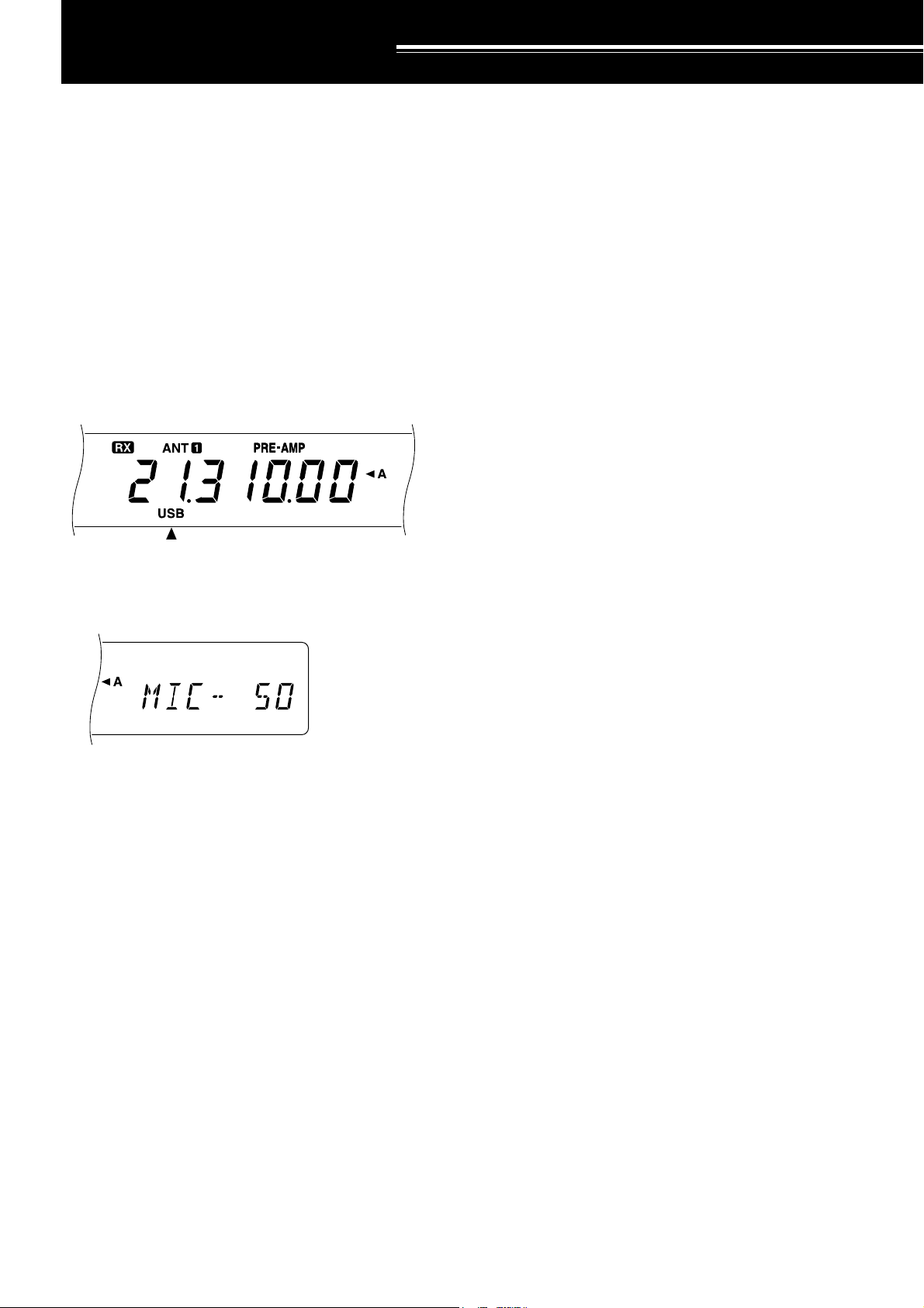
20
BASIC COMMUNICATING
SSB TRANSMISSION
SSB is now the most commonly-used mode on the HF
Amateur bands. Compared with other voice modes,
SSB requires a narrow bandwidth for communications.
SSB also allows long distance communication with
minimum transmit power. These reasons, combined
with the fact that modern Amateur transceivers deliver
reasonably good audio quality, make SSB the mode
that most prefer on HF.
Refer, if necessary, to “OPERATING BASICS”
beginning on page 13 for receiving details.
1 Select the operating frequency.
2 Press [LSB/USB] to select either upper or lower
sideband mode.
• “LSB” or “USB” appears to show which sideband
is selected.
3 Press [MIC] to activate the Microphone Gain Setting
function.
• The current gain level appears
4 Press and hold down Mic [PTT], or press [SEND].
• “RX” disappears and “TX” appears.
• Refer to “VOX” {page 31} for information on
automatic TX/RX switching.
5 Speak into the microphone and adjust the
MULTI/CH control so that the ALC meter reflects
according to your voice level.
• Speak in a normal tone and level of voice.
Speaking too close to the microphone, or too
loudly, may increase distortion and reduce
intelligibility.
•You may want to use the Speech Processor.
Refer to “SPEECH PROCESSOR” {page 32} for
details.
6 Release Mic [PTT], or press [SEND] again, to return
to the receive mode.
• “TX” disappears and “RX” appears.
7 Press [MIC] again to quit the Microphone Gain
Setting function.
Refer to “COMMUNICATING AIDS” beginning on
page29 for information about additional useful functions
for operating.
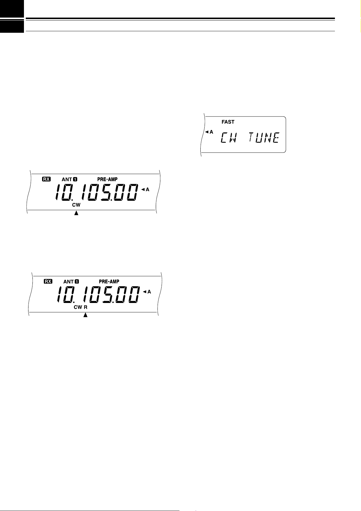
21
6 BASIC COMMUNICATING
CW TRANSMISSION
CW operators know that this mode is a reliable method
of communicating under the worst conditions. Although
it’s true that newer digital modes rival CW as being
equally as useful in poor conditions, these modes do not
have the long history of service yet nor the simplicity
that CW can have.
This transceiver has a built-in electronic keyer that
supports a variety of functions. For details on using
these functions, refer to “ELECTRONIC KEYER”
{page34}.
Refer, if necessary, to “OPERATING BASICS”
beginning on page 13 for receiving details.
1 Select the operating frequency.
2 Press [CW/FSK] to select CW mode.
• “CW” appears.
•To tune in another station so your transceiver is
precisely on their frequency, use Auto Zero-beat.
Refer to “AUTO ZERO-BEAT”.
• If you wish, you can press [REV] to switch
receive from the default upper sideband to the
lower sideband. “R” will appear.
3 Press [SEND].
• “RX” disappears and “TX” appears.
• No transmit carrier level adjustment is necessary.
• Refer to “CW BREAK-IN” {page 34} for
information on automatic TX/RX switching.
4 Begin sending.
• As you transmit, you should be hearing a
sidetone that lets you monitor your own sending.
Refer to “TX SIDETONE/ RX PITCH
FREQUENCY”.
5 Press [SEND] again to return to the receive mode.
• “TX” disappears and “RX” appears.
Note:
Auto Zero-beating may fail if there are other interfering signals
on frequency.
Refer to “COMMUNICATING AIDS” beginning on
page29 for information about additional useful functions
for operating.
AUTO ZERO-BEAT
Use Auto Zero-beat before transmitting whenever you
need to tune in a CW station. Auto Zero-beat
automatically and exactly matches your transmit
frequency with the station that you are receiving.
Neglecting to do this will reduce your chances for being
heard by the other station.
1 Press [CW TUNE] to start Auto Zero-beat.
• “CW TUNE” appears.
•Your transmit frequency is automatically changed
so that the pitch of the received signal exactly
matches the TX sidetone/ RX pitch frequency
that you have set in your transceiver Menu
configuration. Refer to “TX SIDETONE/ RX
PITCH FREQUENCY” below for further
information on that frequency.
• When matching is completed, “CW TUNE”
disappears.
• If matching is unsuccessful, the previous
frequency is restored.
2 To interrupt Auto Zero-beat, press [CW TUNE] or
[CLR].
Note:
◆
If using RIT {page 30}, you may access Menu No. 48 and switch
the function ON. Auto Zero-beat then will match the RIT-offset
frequency with the station that you are receiving. When this
function is OFF, Auto Zero-beat changes the transmit frequency.
◆
You cannot start Auto Zero-beat if you have selected 1.0 kHz or
2.0 kHz for the DSP filter bandwidth.
◆
When using Auto Zero-beat, the matching error is within
±
50 Hz
in most cases.
◆
Auto Zero-beat may fail if the keying speed of the target station is
too slow.
TX SIDETONE/ RX PITCH FREQUENCY
The transmit sidetone is the monitor tone you hear from
your transceiver as you send CW. It is necessary so
you can hear what you are transmitting. It is also useful
for checking that your key contacts are closing, the
keyer is functioning, or for sending practice without
putting a signal on the air.
Receive pitch refers to the frequency of the CW note
that you hear after tuning your receiver for maximum
receive signal strength.
On this transceiver, the frequency of the sidetone and
receive pitch are equal and selectable. Use Menu No.
20 to select the frequency that is most comfortable for
you.
To change the volume of the TX sidetone, use Menu
No. 21. The selections include OFF and 1 to 9. The
default is 4.
Note:
The position of the
AF
control does not affect the volume of
the TX sidetone.
 Loading...