


INSTRUCTION MANUAL
HF/50MHz ALL MODE TRANSCEIVER TS-480
PF |
|
|
|
|
|
|
||
ANT |
1/2 |
|
|
|
|
|
|
|
ATT/PRE |
|
|
|
|
|
|
||
AT |
1 REC |
2 REC |
3 REC |
|
|
|
||
CH1 |
CH2 |
CH3 |
DNL |
|
MODE |
|||
|
|
|
NAR |
|||||
AF |
|
|
SQL 4 TX MONI |
5 RF.G |
6 DELAY |
|
|
|
|
|
NR |
FIL |
F.LOCK |
||||
|
|
|
PWR |
MIC |
KEY |
|||
|
|
|
MENU |
|||||
|
|
|
7 |
8 |
9 |
BC |
CW.T |
|
|
|
|
NB/T |
VOX |
PROC |
|
||
|
|
|
CLR |
0 OFF |
|
STEP |
SG.SEL |
MHz |
|
|
|
MTR |
AGC |
ENT |
FINE |
SCAN |
|
|
|
|
|
|||||
M.IN QMI M VFO QMR
M/V
A / B
SPLIT A=B
CL
XIT
RIT
TF-SET
IF MULTI SHIFT
SHIFT
HF/ 50 MHz ALL MODE TRANSCEIVER
TS-480HX TS-480SAT
© B62-1735-20 (K, E)
09 08 07 06 05 04 03 02

NOTICE TO THE USER
One or more of the following statements may be applicable for this equipment.
FCC WARNING
This equipment generates or uses radio frequency energy. Changes or modifications to this equipment may cause harmful interference unless the modifications are expressly approved in the instruction manual. The user could lose the authority to operate this equipment if an unauthorized change or modification is made.
INFORMATION TO THE DIGITAL DEVICE USER REQUIRED BY THE FCC
This equipment has been tested and found to comply with the limits for a Class B digital device, pursuant to Part 15 of the FCC Rules. These limits are designed to provide reasonable protection against harmful interference in a residential installation.
This equipment generates, uses and can generate radio frequency energy and, if not installed and used in accordance with the instructions, may cause harmful interference to radio communications. However, there is no guarantee that the interference will not occur in a particular installation. If this equipment does cause harmful interference to radio or television reception, which can be determined by turning the equipment off and on, the user is encouraged to try to correct the interference by one or more of the following measures:
•Reorient or relocate the receiving antenna.
•Increase the separation between the equipment and receiver.
•Connect the equipment to an outlet on a circuit different from that to which the receiver is connected.
•Consult the dealer for technical assistance.
BEFORE STARTING
Amateur radio regulations vary from country to country. Confirm your local amateur radio regulations and requirements before operating the transceiver.
Depending on the size and type of vehicle, the maximum transmission output power for the mobile operation will vary. The maximum transmission output power is usually specified by the car manufacturer to avoid interference with other electric devices used in the vehicle. Consult your car manufacturer and amateur radio equipment dealer for the requirements and installation.

THANK YOU
THANK YOU
Thank you for choosing this KENWOOD TS-480HX/ SAT transceiver. It has been developed by a team of engineers determined to continue the tradition of excellence and innovation in KENWOOD transceivers.
This transceiver features a Digital Signal Processing (DSP) unit to process AF signals. By taking maximum advantage of DSP technology, the TS-480HX/ SAT transceiver gives you enhanced interference reduction capabilities and improves the quality of audio. You will notice the differences when you fight QRM and QRN. As you learn how to use this transceiver, you will also find that KENWOOD is pursuing “user friendliness”. For example, each time you change the Menu No. in Menu mode, you will see scrolling messages on the display that tell you what you are selecting.
Though user friendly, this transceiver is technically sophisticated and some features may be new to you. Consider this manual to be a personal tutorial from the designers. Allow the manual to guide you through the learning process now, then act as a reference in the coming years.
FEATURES
•All mode operation from HF to 50 MHz amateur radio band
•Separate Remote Control panel for mobile operation
•Digital Signal Processing (DSP) unit
•Adjustable DSP filter frequencies
•A built-in Antenna Tuner for the HF/ 50 MHz band (TS-480SAT)
•200 watts 1 output power (SSB, CW, FSK, FM) and 50 watts 2 output power (AM) for the TS-480HX.
1 50 MHz: 100 watts
2 50 MHz: 25 watts
•100 watts output power (SSB, CW, FSK, FM) and 25 watts output power (AM) for the TS-480SAT.
SUPPLIED ACCESSORIES
After carefully unpacking the transceiver, identify the items listed in the table below. We recommend you keep the box and packing materials in case you need to repack the transceiver in the future.
|
|
|
|
Quantity |
|
||
|
|
|
|
|
|
|
|
Accessory |
Part Number |
TS-480SAT |
TS-480HX |
||||
|
|
|
|
|
|
|
|
|
|
|
K |
E |
K |
E |
|
|
|
|
|
|
|
|
|
Microphone |
T91-0638-XX |
1 |
1 |
1 |
1 |
||
|
|
|
|
|
|
|
|
DC power cable |
E30-3489-XX |
1 |
1 |
2 |
2 |
||
|
|
|
|
|
|
|
|
mini DIN plug |
E57-0404-XX |
1 |
1 |
1 |
1 |
||
(6-pin male) |
|||||||
|
|
|
|
|
|
||
|
|
|
|
|
|
|
|
mini DIN plug |
E57-0405-XX |
1 |
1 |
1 |
1 |
||
(8-pin male) |
|||||||
|
|
|
|
|
|
||
|
|
|
|
|
|
|
|
Modular cable |
E30-3488-XX |
1 |
1 |
1 |
1 |
||
(RJ-11 4 m) |
|||||||
|
|
|
|
|
|
||
|
|
|
|
|
|
|
|
Modular cable |
E30-3500-XX |
– |
1 |
– |
1 |
||
(RJ-11 20 cm) |
|||||||
|
|
|
|
|
|
||
Fuse (25 A) |
F05-2531-XX |
1 |
1 |
2 |
2 |
||
|
|
|
|
|
|
|
|
Fuse (4 A) |
F06-4027-XX |
1 |
1 |
1 |
1 |
||
|
|
|
|
|
|
|
|
Screw Set for |
N99-2035-XX |
1 |
1 |
1 |
1 |
||
brackets (A) |
|||||||
|
|
|
|
|
|
||
|
|
|
|
|
|
|
|
L-bracket |
J29-0706-XX |
2 |
2 |
2 |
2 |
||
|
|
|
|
|
|
|
|
Panel holder |
J29-0663-XX |
1 |
2 |
1 |
2 |
||
|
|
|
|
|
|
|
|
Panel bracket |
J29-0707-XX |
1 |
1 |
1 |
1 |
||
(mobile) |
|||||||
|
|
|
|
|
|
||
|
|
|
|
|
|
|
|
Panel bracket |
J09-0409-XX |
1 |
1 |
1 |
1 |
||
(base) |
|||||||
|
|
|
|
|
|
||
|
|
|
|
|
|
|
|
Line filter with a |
L79-1408-XX |
– |
1 |
– |
2 |
||
retaining band |
|||||||
|
|
|
|
|
|
||
Line filter for |
L79-1417-XX |
1 |
1 |
1 |
1 |
||
Panel |
|||||||
|
|
|
|
|
|
||
Portable bracket |
J29-0705-XX |
– |
1 |
– |
1 |
||
|
|
|
|
|
|
|
|
Carrying handle |
K01-0420-XX |
– |
1 |
– |
1 |
||
|
|
|
|
|
|
|
|
Screw set for |
|
|
|
|
|
|
|
Portable bracket |
N99-2041-XX |
– |
1 |
– |
1 |
||
(B) |
|
|
|
|
|
|
|
|
B62-1735-XX |
E |
1 |
1 |
1 |
1 |
|
|
|
|
|
|
|
|
|
|
B62-1750-XX |
F |
– |
1 |
– |
1 |
|
|
|
|
|
|
|
|
|
Instruction |
B62-1752-XX |
S |
– |
1 |
– |
1 |
|
Manual |
B62-1736-XX |
G |
– |
1 |
– |
1 |
|
|
|
|
|
|
|
|
|
|
B62-1751-XX |
I |
– |
1 |
– |
1 |
|
|
|
|
|
|
|
|
|
|
B62-1753-XX |
D |
– |
1 |
– |
1 |
|
|
|
|
|
|
|
|
|
Schematic/ |
B52-0619-XX |
1 |
– |
1 |
– |
||
Block Diagrams |
B52-0620-XX |
||||||
|
|
|
|
||||
|
|
|
|
|
|
|
|
Warranty card |
– |
1 |
1 |
1 |
1 |
||
|
|
|
|
|
|
|
|
i

THANK YOU
MODELS COVERED BY THIS MANUAL
The models listed below are covered by this manual.
TS-480HX : HF/ 50 MHz All mode Transceiver (200 watts 1 output power: SSB, CW,
FSK, FM/ 50 watts 2 output power: AM)
1 50 MHz: 100 watts2 50 MHz: 25 watts
TS-480SAT : HF/ 50 MHz All mode Transceiver with Automatic Antenna Tuner (100 watts output power: SSB, CW, FSK, FM/
25 watts output power: AM)
MARKET CODES
K-type |
: |
The Americas |
E-type |
: |
Europe/ General |
The market code is shown on the carton box.
Refer to the specifications {page 91} for information on the available operating frequencies.
WRITING CONVENTIONS FOLLOWED
The writing conventions described below have been followed to simplify instructions and avoid unnecessary repetition.
Instruction |
|
|
What to Do |
|||
|
|
|
|
|
|
|
Press [KEY]. |
Press and release KEY. |
|||||
|
|
|
|
|
|
|
Press |
Press KEY1 momentarily, release |
|||||
[KEY1], [KEY2]. |
KEY1, then press KEY2. |
|||||
|
|
|
|
|
|
|
Press |
Press and hold KEY down for a |
|||||
[KEY] (1 s). |
second and then release KEY. |
|||||
|
|
|
|
|
|
|
|
|
|
Press and hold KEY1 down, then |
|||
Press |
press KEY2. If there are more |
|||||
than two keys, press and hold |
||||||
[KEY1]+[KEY2]. |
||||||
|
|
|
down each key in turn until the |
|||
|
|
|
final key has been pressed. |
|||
|
|
|
|
|
|
|
|
|
|
With the transceiver OFF, press |
|||
Press |
and hold KEY, then switch ON |
|||||
[KEY]+[ |
|
]. |
the transceiver power by pressing |
|||
|
||||||
|
||||||
|
|
|
[ |
|
] (POWER). |
|
|
|
|
|
|||
|
|
|
|
|||
|
|
|
|
|
|
|
ii
PRECAUTIONS
Please observe the following precautions to prevent fire, personal injury, and transceiver damage:
•Connect the transceiver only to a power source described in this manual or as marked on the transceiver itself.
•Route all power cables safely. Ensure the power cables can neither be stepped upon nor pinched by items placed near or against the cables. Pay particular attention to locations near AC receptacles, AC outlet strips, and points of entry to the transceiver.
•Take care not to drop objects or spill liquid into the transceiver through enclosure openings. Metal objects, such as hairpins or needles, inserted into the transceiver may contact voltages resulting in serious electrical shocks. Never permit children to insert any objects into the transceiver.
•Do not attempt to defeat methods used for grounding and electrical polarization in the transceiver, particularly involving the power input cable.
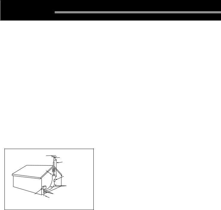
•Adequately ground all outdoor antennas for this transceiver using approved methods. Grounding helps protect against voltage surges caused by lightning. It also reduces the chance of a build-up of static charge.
EXAMPLE OF ANTENNA GROUNDING |
||
|
ANTENNA |
|
|
LEAD IN |
|
GROUND |
WIRE |
|
CLAMP |
ANTENNA |
|
|
||
|
DISCHARGE UNIT |
|
|
GROUNDING |
|
|
CONDUCTORS |
|
ELECTRIC SERVICE |
GROUND CLAMPS |
|
POWER SERVICE |
||
EQUIPMENT |
||
|
GROUNDING ELECTRODE |
|
|
SYSTEM |
|
•Minimum recommended distance for an outdoor antenna from power lines is one and one-half times the vertical height of the associated antenna support structure. This distance allows adequate clearance from the power lines if the support structure fails for any reason.
•Locate the transceiver so as not to interfere with its ventilation. Do not place books or other equipment on the transceiver that may impede the free movement of air. Allow a minimum of
10 cm (4 inches) between the rear of the transceiver and the wall or operating desk shelf.
•Do not use the transceiver near water or sources of moisture. For example, avoid use near a bathtub, sink, swimming pool, or in a damp basement or attic.
•The presence of an unusual odor or smoke is often a sign of trouble. Immediately turn the power OFF and remove the power cable. Contact a KENWOOD service station or your dealer for advice.
•Locate the transceiver away from heat sources such as a radiator, stove, amplifier or other devices that produce substantial amounts of heat.
•Do not use volatile solvents such as alcohol, paint thinner, gasoline or benzene to clean the cabinet of the transceiver. Use a clean cloth with warm water or a mild detergent.
•Disconnect the input power cable from the power source when the transceiver is not used for long periods of time.
•Remove the transceiver’s enclosure only to do accessory installations described in this manual or accessory manuals. Follow provided instructions carefully, to avoid electrical shocks. If unfamiliar with this type of work, seek assistance from an experienced individual, or have a professional technician do the task.
•Enlist the services of qualified personnel in the following cases:
a)The power supply or plug is damaged.
b)Objects have fallen or liquid has spilled into the transceiver.
c)The transceiver has been exposed to rain.
d)The transceiver is operating abnormally or performance has seriously degraded.
e)The transceiver has been dropped or the enclosure damaged.
•Do not attempt to perform any kind of configuration or menu setup configuration while driving your car.
•Do not wear headphones while driving.
•Install the transceiver in a safe and convenient position inside of your vehicle so as not to subject yourself to danger while driving. Consult your car dealer for the transceiver installation to ensure safety.
•HF/ 50 MHz mobile antennas are larger and heavier than VHF/ UHF antennas. Therefore, use a strong and rigid mount to safety and securely install the HF/ 50 MHz mobile antenna.
iii

CONTENTS
NOTICE TO USER |
|
|
BEFORE STARTING |
|
|
THANK YOU |
............................................................. |
i |
FEATURES............................................................... |
|
i |
SUPPLIED ACCESSORIES ..................................... |
i |
|
MODELS COVERED .................BY THIS MANUAL |
ii |
|
MARKET CODES .................................................... |
ii |
|
WRITING CONVENTIONS .................FOLLOWED |
ii |
|
PRECAUTIONS ....................................................... |
iii |
|
CONTENTS ............................................................ |
|
iv |
CHAPTER 1 |
INSTALLATION |
|
MOBILE INSTALLATION ......................................... |
1 |
|
INSTALLATION ..................................EXAMPLE |
1 |
|
REMOTE CONTROL .....PANEL INSTALLATION |
1 |
|
DC POWER ....................CABLE CONNECTION |
2 |
|
ANTENNA ...................................CONNECTION |
2 |
|
IGNITION ................................................NOISE |
2 |
|
FIXED STATION .............................INSTALLATION |
3 |
|
REMOTE CONTROL ....PANEL INSTALLATION |
3 |
|
DC POWER .................SUPPLY CONNECTION |
3 |
|
ANTENNA ...................................CONNECTION |
4 |
|
GROUND ....................................CONNECTION |
4 |
|
LIGHTNING .................................PROTECTION |
4 |
|
PORTABLE BRACKET ..................(E-TYPE ONLY) |
5 |
|
FUSES .................................................................... |
|
5 |
PANEL AND MICROPHONE |
|
|
CONNECTION .................................................... |
6 |
|
PANEL AND MICROPHONE CONNECTION |
|
|
USING PG .....................................-4Z (OPTION) |
6 |
|
ACCESSORY CONNECTIONS |
|
|
TX/ RX UNIT |
|
|
Micropohone .........................................(MIC) |
7 |
|
External .............................Speaker (EXT.SP) |
7 |
|
Keys for ...................CW (PADDLE and KEY) |
7 |
|
REMOTE CONTROL PANEL |
|
|
Headphones .................................(PHONES) |
7 |
|
CHAPTER 2 |
YOUR FIRST QSO |
|
RECEPTION............................................................ |
|
8 |
TRANSMISSION ..................................................... |
9 |
|
CHAPTER 3 |
GETTING ACQUAINTED |
|
REMOTE CONTROL .................................PANEL |
10 |
|
LCD DISPLAY ....................................................... |
13 |
|
TX/ RX UNIT .......................................................... |
|
15 |
REMOTE CONTROL ....................PANEL (REAR) |
17 |
|
MICROPHONE ...................................................... |
17 |
|
CHAPTER 4 |
OPERATING BASICS |
|
SWITCHING .............................POWER ON/OFF |
18 |
|
ADJUSTING ..........................................VOLUME |
18 |
|
AF (AUDIO .......................FREQUENCY) GAIN |
18 |
|
RF (RADIO ......................FREQUENCY) GAIN |
18 |
|
SELECTING .............................VFO A OR VFO B |
18 |
|
SELECTING ............................................A BAND |
19 |
|
SELECTING ............................................A MODE |
19 |
|
ADJUSTING ........................................SQUELCH |
19 |
|
SELECTING ................................A FREQUENCY |
19 |
|
MULTI-FUNCTION METER ................................... |
20 |
|
TRANSMITTING .................................................... |
20 |
|
SELECTING TRANSMISSION POWER ............ |
20 |
|
MICROPHONE GAIN ........................................ |
21 |
|
CHAPTER 5 |
MENU SETUP |
|
WHAT IS A MENU?................................................ |
22 |
|
MENU A/ MENU B ................................................. |
22 |
|
MENU ACCESS .................................................... |
22 |
|
QUICK MENU........................................................ |
22 |
|
PROGRAMMING THE QUICK MENU ............... |
22 |
|
USING THE QUICK MENU ............................... |
22 |
|
MENU CONFIGURATION ..................................... |
23 |
|
ALPHABETICAL FUNCTION LIST......................... |
26 |
|
CHAPTER 6 |
BASIC COMMUNICATIONS |
|
SSB TRANSMISSION ........................................... |
27 |
|
FM TRANSMISSION ............................................. |
27 |
|
AM TRANSMISSION ............................................. |
28 |
|
NARROW BANDWIDTH FOR FM ......................... |
28 |
|
NARROW BANDWIDTH FOR AM ......................... |
28 |
|
CW TRANSMISSION ............................................ |
29 |
|
AUTO ZERO-BEAT ........................................... |
29 |
|
TX SIDETONE/ RX PITCH FREQUENCY ......... |
29 |
|
CHAPTER 7 |
ENHANCED COMMUNICATIONS |
|
SPLIT-FREQUENCY OPERATION ........................ |
30 |
|
TF-SET |
|
|
(TRANSMISSION FREQUENCY SET) .............. |
30 |
|
FM REPEATER OPERATION ................................ |
31 |
|
TRANSMITTING A TONE .................................. |
32 |
|
Activating the Tone Function ......................... |
32 |
|
Selecting a Tone Frequency .......................... |
32 |
|
TONE FREQ. ID SCAN ..................................... |
32 |
|
FM CTCSS OPERATION ....................................... |
33 |
|
CTCSS FREQ. ID SCAN ................................... |
33 |
|
CHAPTER 8 |
COMMUNICATING AIDS |
|
RECEPTION |
.......................................................... |
34 |
SELECTING ....................YOUR FREQUENCY |
34 |
|
Direct Frequency .................................Entry |
34 |
|
Using the ........................................MHz key |
34 |
|
Quick QSY.................................................... |
34 |
|
Configuring the Tuning control as |
|
|
MULTI control .......................................(FM) |
34 |
|
Fine Tuning ................................................... |
35 |
|
Tuning ......................control adjustment rate |
35 |
|
Equalizing ..............VFO Frequencies (A=B) |
35 |
|
RIT (RECEIVE .....INCREMENTAL TUNING) |
35 |
|
AGC (AUTOMATIC ...............GAIN CONTROL) |
35 |
|
TRANSMISSION ................................................... |
36 |
|
VOX (VOICE .............-OPERATED TRANSMIT) |
36 |
|
Microphone .................................Input Level |
36 |
|
Delay Time ................................................... |
36 |
|
Anti-VOX ....................................Adjustment |
36 |
|
VOX Source ................................................. |
36 |
|
SPEECH PROCESSOR .................................... |
37 |
|
XIT (TRANSMIT .......INCREMENTAL TUNING) |
37 |
|
CUSTOMIZING TRANSMISSION SIGNAL |
|
|
CHARACTERISTICS ......................................... |
38 |
|
iv

CONTENTS
TX Filter Bandwidth (SSB/ AM) ..................... |
38 |
|
TX Equalizer (SSB/ FM/ AM) ......................... |
38 |
|
TRANSMIT INHIBIT ........................................... |
38 |
|
BUSY LOCKOUT .............................................. |
38 |
|
CHANGING FREQUENCY WHILE |
|
|
TRANSMITTING ................................................ |
38 |
|
CW BREAK-IN ....................................................... |
39 |
|
USING SEMI BREAK-IN OR |
|
|
FULL BREAK-IN ................................................ |
39 |
|
ELECTRONIC KEYER .......................................... |
39 |
|
CHANGING KEYING SPEED ............................ |
39 |
|
AUTO WEIGHTING ........................................... |
39 |
|
Reverse Keying Weight Ratio ....................... |
39 |
|
BUG KEY FUNCTION ....................................... |
40 |
|
CW MESSAGE MEMORY ................................. |
40 |
|
Storing CW Messages .................................. |
40 |
|
Checking CW Messages without |
|
|
Transmitting .................................................. |
40 |
|
Transmitting CW Messages .......................... |
40 |
|
Changing the Inter-message Interval Time .... |
41 |
|
Changing the Sidetone Volume ..................... |
41 |
|
Inset Keying .................................................. |
41 |
|
FREQUENCY CORRECTION FOR CW ............ |
41 |
|
AUTO CW TX IN SSB MODE ............................ |
41 |
|
MIC UP/ DWN KEY PADDLE MODE ................. |
41 |
|
SWAP DOT AND DASH PADDLE POSTION ..... |
41 |
|
CHAPTER 9 |
SPECIALIZED COMMUNICATIONS |
|
RADIO TELETYPE (RTTY) .................................... |
42 |
|
AMTOR/ PacTOR/ CLOVER/ G-TOR/ PSK31 ........ |
43 |
|
PACKET RADIO .................................................... |
43 |
|
SLOW SCAN TV/ FACSIMILE ............................... |
44 |
|
CHAPTER 10 |
REJECTING INTERFERENCE |
|
IF FILTER .............................................................. |
|
45 |
CHANGING THE IF FILTER BANDWIDTH ........ |
45 |
|
SSB/ AM ....................................................... |
45 |
|
CW/ FSK ...................................................... |
45 |
|
FM ................................................................ |
|
45 |
IF SHIFT (SSB/ CW/ FSK) ................................. |
45 |
|
DSP FILTERS |
|
|
CHANGING THE DSP FILTER BANDWIDTH .... |
46 |
|
SSB/ FM/ AM ................................................ |
46 |
|
CW/ FSK ...................................................... |
46 |
|
BEAT CANCEL (SSB/ FM/ AM) .......................... |
47 |
|
NOISE REDUCTION (ALL MODES) .................. |
47 |
|
Setting the NR1 Level Adjustment ................. |
47 |
|
Settign the NR2 Time Constant ..................... |
47 |
|
NOISE BLANKER .................................................. |
47 |
|
DIGITAL NOISE LIMITER (DNL) ............................ |
47 |
|
DSP FILTER FOR DATA COMMUNICATION |
|
|
(SSB/ FM) .............................................................. |
|
48 |
DSP RX MONITOR................................................ |
48 |
|
PRE-AMPLIFIER ................................................... |
49 |
|
ATTENUATOR ....................................................... |
49 |
|
CW REVERSE ...................................................... |
49 |
|
CHAPTER 11 |
MEMORY FEATURES |
|
MEMORY CHANNELS .......................................... |
50 |
|
STORING DATA IN MEMORY ........................... |
50 |
|
Simplex Channels ......................................... |
50 |
|
Split-Frequency Channels ............................. |
51 |
|
MEMORY RECALL AND SCROLL .................... |
51 |
|
Memory Recall.............................................. |
51 |
|
Memory Scroll............................................... |
52 |
|
Temporary Frequency Changes .................... |
52 |
|
MEMORY TRANSFER ...................................... |
52 |
|
Memory VFO Transfer .............................. |
52 |
|
Channel Channel Transfer ........................ |
52 |
|
STORING FREQUENCY RANGES ................... |
53 |
|
Confirming Start/End Frequencies ................ |
53 |
|
Programmable VFO ...................................... |
54 |
|
MEMORY CHANNEL LOCKOUT ....................... |
54 |
|
ERASING MEMORY CHANNELS ..................... |
54 |
|
MEMORY CHANNEL NAME ............................. |
54 |
|
QUICK MEMORY .................................................. |
55 |
|
STORING INTO QUICK MEMORY .................... |
55 |
|
RECALLING QUICK MEMORY CHANNELS ..... |
55 |
|
TEMPORARY FREQUENCY CHANGES .......... |
55 |
|
QUICK MEMORY VFO TRANSFER .............. |
55 |
|
CHAPTER 12 |
SCAN |
|
NORMAL SCAN .................................................... |
56 |
|
VFO SCAN |
........................................................ |
56 |
PROGRAM SCAN ............................................. |
56 |
|
PROGRAM SCAN PARTIALLY SLOWED .......... |
57 |
|
SCAN HOLD ..................................................... |
57 |
|
MEMORY SCAN.................................................... |
58 |
|
SCAN RESUME METHOD ................................ |
58 |
|
ALL-CHANNEL SCAN ....................................... |
58 |
|
GROUP SCAN .................................................. |
59 |
|
Memory Group ............................................. |
59 |
|
Scan Group Select........................................ |
59 |
|
Performing Group Scan ................................ |
59 |
|
CHAPTER 13 |
OPERATOR CONVENIENCES |
|
ANTENNAS ........................................................... |
|
60 |
APO (Auto Power OFF) ......................................... |
60 |
|
AUTOMATIC ANTENNA TUNER ........................... |
60 |
|
PRESETTING ................................................... |
61 |
|
EXTERNAL ANTENNA TUNER TYPE ............... |
61 |
|
ATTENUATOR ....................................................... |
61 |
|
AUTO MODE ......................................................... |
|
61 |
BEEP FUNCTION .................................................. |
62 |
|
DISPLAY ............................................................... |
|
63 |
BRIGHTNESS ................................................... |
63 |
|
KEY ILLUMINATION .......................................... |
63 |
|
LINEAR AMPLIFIER CONTROL ............................ |
63 |
|
LOCK FUNCTIONS ............................................... |
63 |
|
FREQUENCY LOCK FUNCTION ...................... |
63 |
|
TUNING CONTROL LOCK FUNCTION ............. |
63 |
|
MICROPHONE PF KEYS ...................................... |
64 |
|
PF KEY.................................................................. |
|
64 |
RX DSP EQUALIZER ............................................ |
64 |
|
EQUALIZING RECEIVING AUDIO..................... |
64 |
|
RX MONITOR |
........................................................ |
64 |
v
CONTENTS
TIME-OUT TIMER ................................................. |
65 |
TRANSVERTER .................................................... |
65 |
FREQUENCY DISPLAY .................................... |
65 |
TRANSMISSION OUTPUT POWER.................. |
65 |
TX MONITOR ........................................................ |
65 |
TX POWER ........................................................... |
65 |
TX TUNE ............................................................... |
66 |
QUICK DATA TRANSFER ..................................... |
67 |
SETTING UP ..................................................... |
67 |
Equipment Needed ....................................... |
67 |
Connections ................................................. |
67 |
USING QUICK TRANSFER ............................... |
67 |
Transferring Data .......................................... |
67 |
Receiving Data ............................................. |
67 |
COMPUTER CONTROL ........................................ |
68 |
SETTING UP ..................................................... |
68 |
Equipment Needed ....................................... |
68 |
Connections ................................................. |
68 |
COMMUNICATION PARAMETERS ................... |
68 |
CONTROLLING THE TS-480 FROM PC ........... |
68 |
REMOTE CONTROLLING THE TS-480 |
|
ON THE NETWORK .......................................... |
68 |
VGS-1 VOICE GUIDE AND STORAGE UNIT |
|
(OPTIONAL) .......................................................... |
68 |
RECORDING MESSAGES ................................ |
68 |
MESSAGE PLAYBACK ..................................... |
69 |
Checking Messages ..................................... |
69 |
Sending Messages ....................................... |
69 |
Erasing a Recorded Message ....................... |
69 |
Changing Inter-message Interval Time .......... |
69 |
Changing Playback Volume .......................... |
69 |
CONSTANT RECORDING ................................ |
69 |
VOICE GUIDE ................................................... |
70 |
Voice Guide Announcement Volume ............. |
71 |
Voice Guide Announcement Speed ............... |
71 |
DX PACKETCLUSTER TUNE ............................... |
72 |
SKY COMMAND II (K-TYPE ONLY) ...................... |
73 |
SKY COMMAND II DIAGRAM ........................... |
73 |
PREPARATION ................................................. |
73 |
CONTROL OPERATION ................................... |
73 |
USING THE TH-D7A AS A COMMANDER ......... |
74 |
CONTROL OPERATION ................................... |
74 |
CHAPTER 14 CONNECTING PERIPHERAL EQUIPMENT |
|
COMPUTER .......................................................... |
76 |
COMPATIBLE TRANSCEIVER .............................. |
76 |
RTTY OPERATION ................................................ |
77 |
HF/ 50 MHz LINEAR AMPLIFIER .......................... |
77 |
ANTENNA TUNER ................................................ |
78 |
MCP AND TNC ...................................................... |
78 |
DX PACKETCLUSTER TUNE ............................... |
79 |
CROSSBAND REPEATER .................................... |
79 |
SKY COMMAND II (K-TYPE ONLY) ...................... |
80 |
CHAPTER 15 INSTALLING OPTIONS |
|
REMOVING THE TOP COVER ............................. |
81 |
VGS-1 VOICE GUIDE AND STORAGE UNIT ........ |
81 |
YF-107C/ CN/ SN IF FILTERS AND |
|
|
SO-3 TCXO ........................................................... |
|
81 |
REFERENCE FREQUENCY CALIBRATION ..... |
82 |
|
CHAPTER 16 |
TROUBLESHOOTING |
|
GENERAL INFORMATION .................................... |
83 |
|
SERVICE ........................................................... |
|
83 |
SERVICE NOTE ................................................ |
83 |
|
CLEANING |
........................................................ |
83 |
BACKUP BATTERY ............................................... |
83 |
|
TROUBLESHOOTING ........................................... |
84 |
|
MICROPROCESSOR RESET ............................... |
88 |
|
INITIAL SETTINGS ............................................ |
88 |
|
PARTIAL RESET ............................................... |
88 |
|
FULL RESET ..................................................... |
88 |
|
DEMONSTRATION MODE .................................... |
88 |
|
OPERATION NOTICES ......................................... |
89 |
|
DC POWER SUPPLY ........................................ |
89 |
|
FAN NOISES ..................................................... |
89 |
|
INTERNAL BEATS ............................................ |
89 |
|
AGC .................................................................. |
|
89 |
60 m BAND OPERATION |
|
|
(K-TYPE/ USA ONLY) ........................................ |
89 |
|
CHAPTER 17 |
OPTIONAL ACCESSORIES |
|
OPTIONAL ACCESSORIES .................................. |
90 |
|
CHAPTER 18 |
SPECIFICATIONS |
|
SPECIFICATIONS ................................................. |
91 |
|
CHAPTER 19 |
INDEX |
|
INDEX ................................................................... |
|
93 |
vi

INSTALLATION
MOBILE INSTALLATION
When you use this transceiver for mobile operation, do not attempt to perform any kind of configuration or menu setup configuration while driving your car; it is simply too dangeous. Stop the car and then perform transceiver configuration. In addition, do not wear headphones while driving.
You should install the transceiver in a safe and convenient position inside your vehicle so as not to subject yourself to danger while driving. For example, install the transceiver under the dash in front of the passenger seat so that knees or legs will not strike the transceiver if you brake suddenly. Additionally, do not install the transceiver and its accessories on to the air bag lids. We recommend you consult your car dealer for the transceiver installation to ensure safety.
INSTALLATION EXAMPLE
1Attach the 2 L-brackets using the 6 supplied SEMS screws (M4 x 10 mm) as shown below.
2Position the transceiver in the mounting bracket and tighten the 4 supplied tapping screws (5 mm x 16 mm) to fix the transceiver in place.
Tapping screw (5 mm x 16 mm)
Flat washer  (5 mm)
EXT.SP |
DATA |
REMOTE |
|
||
MIC |
|
|
|
|
|
P |
|
|
ANEL |
|
|
|
|
COM |
P |
|
ADDLE |
KEY |
|
|
SEMS screw |
L-bracket |
(M4 x 10 mm) |
|
Do not install the TX/ RX unit in non-ventilated areas. Air must flow through the TX/ RX unit to keep the unit cooled.
REMOTE CONTROL PANEL INSTALLATION
1Peel off the adhesive tape cover from the bottom of the fan-shaped base.
2Afix the holder to the vehicle with 4 tapping screws.
3Attach the Remote Control panel holder to the base with 2 supplied SEMS screws.
Tapping screw
 4 mm x 12 mm
 Flat washer (4 mm)
Remote Control panel holder
 SEMS screws
(M4 x 10 mm)
Adhesive tape cover
1
1 INSTALLATION
DC POWER CABLE CONNECTION
Connect the DC power cable directly to the vehicle’s battery terminals using the shortest route. Do not use the cigarette lighter socket! The current rating of the cigarette lighter socket is too small to operate the transceiver. Ensure to use a 12 V vehicle battery which has sufficient current capacity. If the current is insufficient, the display may darken during transmission or the trasceiver may work intermittiently. If you use the transceiver for a long period when the vehicle battery has not been fully charged or when the engine has been stopped, the battery may become discharged in a short time and will not have sufficient reserves to start the engine. Avoid using the transceiver under these conditions. Keep in mind that the TS-480SAT transceiver draws a peak current of approximately 20.5 A and the TS-480HX transceiver draws a peak current of approximately 41A (20.5A + 20.5A) during transmission.
•Attach the line filter(s) to the DC cable(s) as shown after the installation (E-type only).
Place the DC cable the wall of the engine compartment securely. Avoid applying excessive heat, vapor and water to the cable.
Engine compartment 
Red (+) |
|
|
Passenger |
|
AT |
|
|
|
Compartment |
|
DC 2 13.8V |
|
2 |
1 |
Black (ó) |
1 |
GND |
DC |
||
13.8V |
|
|


 Body
Body
DC IN
12 |
V battery |
|
TS-480SAT |
|
|
Use a rubber or plastic grommet so that the cable |
|||
|
|
does not directly touch the vehicle chassis. |
|
|
|
|
|
Place the DC cable the wall of the engine compartment |
|
Engine compartment |
securely. Avoid applying excessive heat, vapor and water to |
|||
the cable. |
|
|||
|
|
|
Red (+) |
|
|
|
|
Passenger |
|
|
|
|
Compartment |
|
|
|
Black (ñ) |
|
|
|
|
|
Body |
DC IN 2 |
|
|
|
DC IN 1 |
|
|
|
|
|
|
12 |
V battery |
Use a rubber or plastic grommet so that the cable |
TS-480HX |
|
|
||||
|
|
|
does not directly touch the vehicle chassis. |
|
Note: |
E-type only |
|
Do not use two separate batteries to connect each DC cables from the transceiver (TS-480HX). The DC voltage difference
between DC IN 1 and DC IN 2 connectors at the transceiver must be within DC 1.0 V to operate the transceiver.
Two supplied DC cables (or two optional PG-20 DC cables) must be used. Using different length and/ or different gauged cable could result in a voltage difference between DC IN 1 and DC IN 2 connectors at the transceiver (TS-480HX).
ANTENNA CONNECTION
In general, HF/ 50 MHz mobile antennas are larger and heavier than VHF/ UHF antennas. Therefore, use a strong and rigid mount to safety and securely install the HF/ 50 MHz mobile antenna.
A bumper mount is recommended for stable mounting. However, most recent models of vehicles have plastic bumpers. For such vehicles, ground the antenna mount to the body chassis with a large wire. Antenna installation is critical for successful mobile operation. For further information, refer to The Radio Amateur’s Handbook, Radio Handbook, or other published texts.
GROUND CONNECTION
The ground, which is the other half of the antenna system, is very important when using a mobile whip type antenna. Connect the feed line ground for the antenna securely to the vehicle’s chassis, and be certain to bond (electrically connect) the vehicle’s body to chassis. The sheet metal will provide the primary ground plane, so be sure to establish a good RF connection from the feed line to both the chassis and the body. For comprehensive information on mobile antennas installations and optimization, refer to the ARRL Handbook or similar publications.
IGNITION NOISE
This transceiver has been equipped with a Noise Blanker and Digital Noise Limiter to filter ignition noises out. However, some cars may generate excessive ignition noise. If there is excessive noise, use suppressor spark plugs (with resisters), and/ or DC line filters to reduce the electric noises. The ARRL Handbook, or similar refereneces, has a wealth of information regarding this topic.
Note:
After installation and wiring are completed, confirm that all work has been done correctly, then connect the DC power cable plug(s) to the transceiver.
If the fuse blows, disconnect the DC power cable plug(s) from the transceiver immediately, then check all the DC power cables to find the reasons of the short circuit. The DC cable may be damaged, short circuited, pinched, or squashed. After resolving the problem, replace the fuse with one of the same type and rating.
Do not remove the fuse holder for any reason.
2
1 INSTALLATION
FIXED STATION INSTALLATION
When you use the transceiver at a fixed location, the transceiver requires 13.8 V DC power supply (The TS-480HX requires 2 DC power supplies).
REMOTE CONTROL PANEL INSTALLATION
1Attach the oval-shaped base to the front panel mounting bracket using two SEMS screws (M4 x 10 mm) as shown below.
2Slide the Remote Control panel along the mounting bracket rails until secure.
|
SEMS screw |
|
|
(M4 x 10 mm) |
|
Panel holder |
|
|
SEMS screw |
Base stand |
|
(M4 x 10 mm) |
||
|
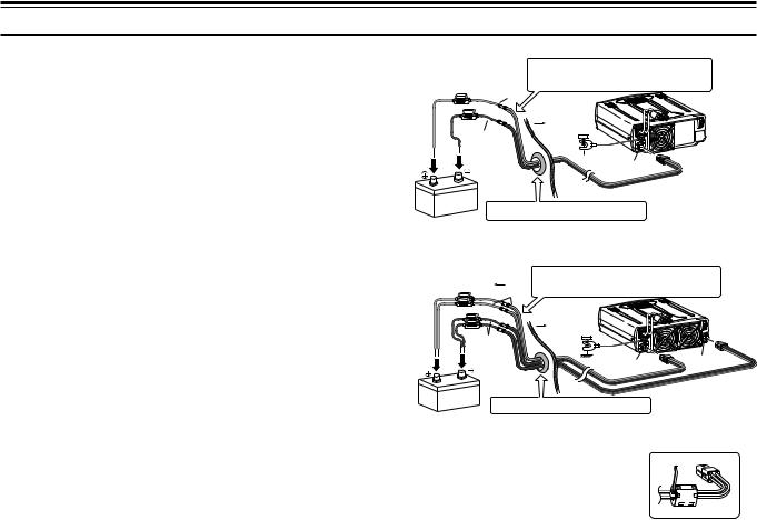
DC POWER SUPPLY CONNECTION
In order to use this transceiver, you need a separate 13.8 V DC power supply (two 13.8 V/ 20.5 A or single 13.8 V/ 41.0 A DC power supply(s) is required to transmit for the TS-480HX) that must be purchased separately. Do not directly connect the transceiver to an AC outlet. Use the supplied DC power cables to connect the
transceiver to a regulated power supply. Do not substitute a cable with smaller gauge wires. The current capacity of each power supply must be 20.5 A peak or more.
1Connect the DC power cable(s) to the regulated DC power supply (two 13.8 V/ 20.5 A or single 13.8 V/ 41.0 A DC power supply(s) must be used for the TS-480HX); the red lead to the positive terminal and the black lead to the negative terminal.
•When using a single 13.8 V/ 41 A DC power supply, connect 2 DC cables to the positive and negative terminals, as shown on page 2.
2Connect the DC power cable to the transceiver’s DC power connector.
•Press the connectors firmly until the locking tab clicks.
•Attach the line filter(s) to the DC cable(s) as shown below (E-type only).
Note:
Before connecting the DC power supply to the transceiver, be sure to switch OFF the DC power supply and the transceiver.
Do not plug the DC power supply into an AC outlet until you make all connections.
When two power supplies are used for the TS-480HX, the DC voltage difference at the transceiver DC IN connectors must be within 1.0 V DC.
Do not use different types (length and gauge) of DC cables to avoid voltage differences (TS-480HX).
E-type only
 Fuse (25 A)
Black (ó)
Red (+)
|
|
AT |
|
2 |
1 |
|
|
DC 2 13.8V |
DC |
1 |
GND |
13.8V |
|
|
|
|
Fuse (25 A) |
|
|
Red (+) |
Fuse (25 A) |
|
Black (ñ) |
|
|
|
|
Red (+) |
|
|
2 |
1 |
|
|
2 13.8V |
DC |
1 |
GND |
13.8V |
|
|
|
|
|
|
|
DC IN 2 |
DC Power supply |
DC IN 1 |
|
DC Power supply |
DC IN 1 |
DC 13.8 V |
|
|
||||
(20.5 A or more) |
DC 13.8 V |
DC Power supply |
(20.5 A or more) |
DC 13.8 V |
|
|
|
||||
|
TS-480SAT |
(20.5 A or more) |
|
|
TS-480HX |
|
|
|
|
3

1 INSTALLATION
ANTENNA CONNECTION
An antenna system consists of an antenna, feed line, and ground. The transceiver can give excellent results if the antenna system and its installation are given careful attention. Use a properly adjusted 50 Ω antenna of good quality, a high-quality 50 Ω coaxial cable, and first-quality connectors. All connections must be clean and tight.
After making the connections, match the impedance of the coaxial cable and antenna so that the SWR is 1.5:1 or less. High SWR will cause the transmit output to drop and may lead to radio frequency interference to consumer products such as stereo receivers and televisions. You may even interfere with your own transceiver. Reports that your signal is distorted could indicate that your antenna system is not efficiently radiating the transceiver’s power.
Connect your primary HF/ 50 MHz antenna feed line to ANT 1 on the rear of the transceiver. If you are using two HF/ 50 MHz antennas, connect the secondary antenna to ANT 2. Refer to page 16 for the location of the antenna connectors.
Note:
Transmitting without connecting an antenna or other matched load may damage the transceiver. Always connect the antenna to the transceiver before transmitting.
All fixed stations should be equipped with a lightning arrester to reduce the risk of fire, electric shock, and transceiver damage.
The transceiverís protection circuit will activate when the SWR is greater than 2.5:1; however, do not rely on protection to compensate for a poorly functioning antenna system.
GROUND CONNECTION
At the minimum, a good DC ground is required to prevent such dangers as electric shock. For superior communications results, a good RF ground is required against which the antenna system can operate. Both of these conditions can be met by providing a good earth ground for your station. Bury one or more ground rods or a large copper plate under the ground, then connect this to the transceiver GND terminal. Use heavy gauge wire or a copper strap, cut as short as possible, for this connection. Do not use a gas pipe, an electrical conduit, or a plastic water pipe as a ground.
LIGHTNING PROTECTION
Even in areas where lightning storms are less common, there are usually a limited number of storms each year. Consider carefully how to protect your equipment and home from lightning. The installation of a lightning arrestor is a start, but there is more that you can do. For example, terminate your antenna system transmission lines at an entry panel that you install outside your home. Ground this entry panel to a good outside ground, then connect the appropriate feed lines between the entry panel and your transceiver. When a lightning storm occurs, disconnecting the feed lines from your transceiver will ensure additional protection.
4

1 INSTALLATION
PORTABLE BRACKET (E-TYPE ONLY)
Using the supplied Portable Bracket, you can carry the Remote Control panel and TX/ RX unit together.
Two TX/ RX unit positions are available. If you do not use the EXT.SP, REMOTE and DATA connectors, place the TX/ RX unit in front position. If you use the EXT.SP, REMOTE or DATA connector, place the TX/ RX unit to the back position. You can also attach the handle as shown if necessary. Use the supplied short cable (RJ11/ 20 cm) to connect the Remote Control panel and the TX/ RX unit.
Binding head screw (M4 x 8 mm)
RJ11/ 20 cm
SEMS screw (M4 x 10 mm)
SEMS screw (M4 x 10 mm)
2 |
1 |
DC 2 13.8V
DC 1 13.8V
 GND
GND
Flat-head screw |
Carrying handle |
|
(M4 x 12 mm) |
||
|
FUSES
The following fuses are used in the TS-480HX/ SAT transceiver. If a fuse blows, determine the cause then correct the problem. Only after the problem has been resolved, replace the blown fuse with a new one with the specified ratings. If newly installed fuses continue to blow, disconnect the power plug and contact a KENWOOD service center or your dealer for assistance.
1 |
Remove 7 screws at the bottom of the TX/ RX unit. |
Fuse Location |
Fuse Current Rating |
|
|
|
|||
TS-480HX/ SAT |
4 A |
|||
2 |
|
|||
Remove 8 screws inside of the TX/ RX unit. |
(TX/ RX unit) |
(For an external antenna tuner) |
||
|
|
|
|
|
3 |
Lift the shield cover. |
Supplied DC power |
25 A |
|
|
|
cable |
||
4 |
Replace 4 A fuse. |
|
||
|
|
|||
|
|
|
|
KEY |
ADDLEP |
COM |
|
|
|
|
|
ANEL P |
|
REMOTE |
|
|
MIC |
ATAD |
|
|
|
|
SP.EXT |
|
|
|
|
|
|
|
KEY |
DDLEPA |
COM |
|
|
|
|
|
ANEL P |
|
REMOTE |
|
|
MIC |
ATAD |
|
|
|
|
SP.EXT |
|
|
|
|
|
5

1 INSTALLATION
PANEL AND MICROPHONE CONNECTION
Plug the microphone plug to the MIC jack (8-wire/ RJ45), then connect the Remote Control panel to the TX/ RX unit with the supplied cable (2 m/ 6-wire/ RJ11).
Microphone
To MIC
3cm
EXT.SP |
DATA |
REMOTE |
|
||
MIC |
|
|
|
|
|
PANEL |
|
|
|
|
COM |
P |
|
ADDLE |
KEY |
To PANEL
Line filter
PANEL AND MICROPHONE CONNECTION USING PG-4Z (OPTION)
Use the cables and connectors to connect the Remote Control panel and TX/ RX unit with the PG-4Z cable kit as shown below.
Extension cable (RJ45)
from the PG-4Z cable kit
Extension adaptor (RJ45) from the PG-4Z cable kit
PANEL
 EXT.SP
  DATA
DATA
REMOTE
Cable holder
Line filter (large) from the PG-4Z cable kit
Line filter (small) from the TS-480
To MIC
|
|
|
MIC |
|
|
3 |
cm |
|
|
|
|
|
|
|
|
|
|
P |
|
|
|
|
ADDLE |
KEY |
|
|
|
|
|
3 |
cm |
To EXT.SP |
||
|
|
|||
1 |
cm |
|
Line filter (small) from the PG-4Z cable kit
Tapping screw
 (4 mm x 14 mm)
Flat washer
Microphone cable
RJ45 (8-wire) adaptor
Double-sided adhesive tape
EXT.SP |
DATA |
REMOTE |
|
||
|
|
PANEL
COM
To external speaker
|
External speaker extension |
Extension cable (RJ11) |
cable from the PG-4Z cable |
from the PG-4Z cable kit |
kit (when the external speaker |
|
is used) |
|
Extension adaptor (RJ11) |
|
from the PG-4Z cable kit |
6
ACCESSORY CONNECTIONS
TX/ RX UNIT
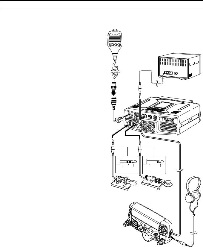
■Microphone (MIC)
Connect a microphone having an impedance between 250 and 600 Ω. As for the supplied microphone, fully insert the modular connector into the MIC jack until the locking tab clicks. You can still utilize 8-pin metal type plug microphones, such as MC-43S, MC-47, and MC-60A with the optional MJ-88 adaptor (optional) if necessary. However, do not use the MC-44, MC-44DM, MC-45, MC-45E, MC-45DM, MC-45DME, or MC-53DM condensor-type microphones.
■External Speaker (EXT.SP)
On the front panel of the TX/ RX unit, there is an external speaker jack. If an external speaker is connected to EXT.SP jack, the built-in speaker on the back of the Remote Control panel will mute. Use only external speakers with an impedance of 4 to 8 Ω (8 Ω nominal). The jacks accept only
3.5 mm (1/8") diameter, 2-conductor (mono) plugs.
•The “ ” projection indicates the external speaker jack.
Note: Do not connect headphones to this jack. The high audio output of this jack could damage your hearing.
■Keys for CW (PADDLE and KEY)
For CW operation using the internal electronic keyer, connect a keyer paddle to the PADDLE jack. For CW operation without using the internal electronic keyer, connect a straight key, semi-automatic key (bug), electronic keyer, or the CW keying output from a Multi-mode Communications Processor (MCP) to the KEY jack. The PADDLE and KEY jacks mate with a 3.5 mm (1/8") 3-conductor plug and a 3.5 mm (1/8") 2-conductor plug respectively. External electronic keyers or MCPs must have a positive keying output to be compatible with this transceiver. Use a shielded cable between the key and the transceiver.
•The “•” projection indicates the key jack and the “••” projection indicates the paddle jack.
Note: Due to the functionality of the internal electronic keyer, you may find it unnecessary to connect both a paddle and another type of keyer unless you want to use a PC-based keyer for CW. Refer to the ìELECTRONIC KEYERî section {page 39} to become familiar with the internal keyer.
REMOTE CONTROL PANEL
■Headphones (PHONES)
Connect monaural or stereo headphones having a 4 to 32 Ω impedance. This jack accepts a
3.5 mm (1/8") diameter, 2-conductor (mono) or
3-conductor (stereo) plug. After connecting the headphones, you will hear no sound from the internal (or optional external) speaker.
1 INSTALLATION
1 |
2 |
3 |
4 |
External speaker (Opt.)
Microphone
w/ 8-pin metal plug (Opt.)
MJ-88 (Opt.)
EXT.SP |
DATA |
REMOTE |
|
||
MIC |
|
|
|
|
|
PANEL |
|
|
|
|
COM |
PAD |
|
DLE |
KEY |
|
GND dash dot |
GND |
+ |
Headphones
Paddle |
Straight key |
|
Bug key |
||
|
||
|
Electric keyer |
|
|
MCP CW output |
7
YOUR FIRST QSO
RECEPTION
w
HF/50MHz ALL MODE TRANSCEIVER TS-480
PF
ANT 1/2
ATT/PRE
r |
AT |
1 REC |
2 REC |
3 REC |
|
|
|
|
|
CH1 |
CH2 |
CH3 |
DNL |
NAR |
MODE |
|
AF SQL 4 TX MONI |
5 RF.G |
6 DELAY |
|
|
||
|
NR |
FIL |
F.LOCK |
||||
|
|
PWR |
MIC |
KEY |
|||
|
|
|
|||||
|
|
7 |
8 |
9 |
BC |
|
MENU |
qu |
|
NB/T |
VOX |
PROC |
CW.T |
|
|
|
|
|
|||||
|
CLR |
0 OFF |
|
STEP |
SG.SEL |
MHz |
|
|
|
MTR |
AGC |
ENT |
FINE |
SCAN |
|
|
|
|
|||||
qr
y i
CL
XIT
RIT
 t
t
M.IN |
TF-SET |
|
QMI |
||
M VFO |
MULTI |
IF |
QMR |
SHIFT |
|
|
|
|
M/V |
|
|
A / B |
|
|
SPLIT |
|
|
A=B |
|
|
e
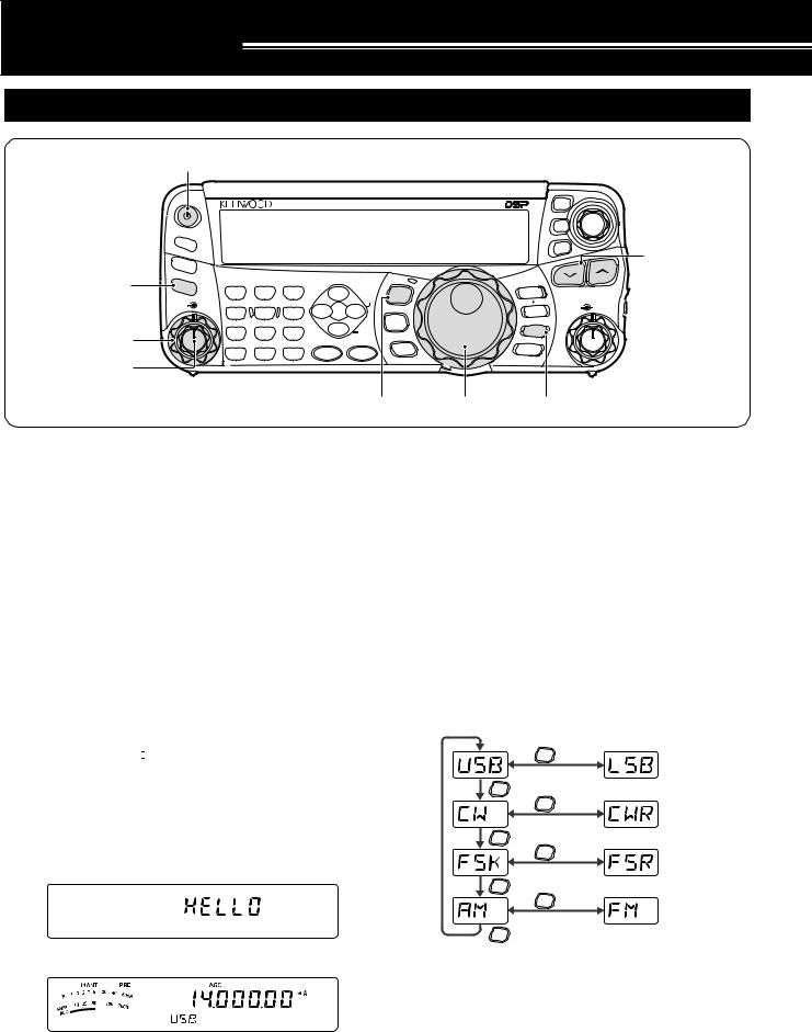
Are you ready to give your TS-480HX/ SAT a quick try? Reading these two pages should get your voice on the air in your first QSO on the HF/ 50 MHz band shortly. The instructions below are intended only for a quick guide. If you encounter problems or there is something you don’t understand, read the detailed explanations given later in this manual.
Note: This section explains only keys and controls required to briefly try the transceiver.
q Set the following as specified:
• |
AF control: |
Fully counterclockwise |
• |
SQL control: |
Fully counterclockwise |
Then, switch ON the DC power supply if you are using the DC power supply. If you are operating the transceiver with the car batteries, ensure that the DC power source(s) are available at the DC connector(s).
wPress and hold [  ] (POWER) briefly to turn ON the transceiver.
•Do not press the switch for more than approximately 2 seconds; the transceiver will be switched OFF.
•Upon power up, “HELLO” appears, followed by the selected frequency and other indicators.
d
eConfirm that VFO A has been selected for communications; “tA” should be visible on the display. If it has not, press [A/B / M/V] to select VFO A.
rTurn the AF control slowly clockwise until you hear a suitable level of background noise.
tPress [ ]/ [
]/ [ ] to select a desired HF/ 50 MHz Amateur radio band.
yPress [MODE] to select the desired communication mode.
•There are 4 mode pairs: USB/ LSB, CW/ CWR (Reversed pitch), FSK/ FSR (Reverse shift) and AM/ FM. Press [MODE] (1 s) to toggle the
mode within each pair: USB  LSB,
LSB,
CW  CWR, FSK
  FSR, or AM
  FM.
FM.
•To select the alternate mode on each operating mode, press and hold the key for 1 second. For example, if USB is selected, press [MODE] (1 s) to switch to LSB mode. The following diagram illustrates how to access each mode.
MODE (1 s)
MODE
MODE (1 s)
MODE
MODE (1 s)
MODE
MODE (1 s)
MODE
uIf you have selected FM, turn the SQL control clockwise until the background noise is just eliminated; the green LED (above the [MODE] key) turns OFF.
• With LSB or USB selected, skip this step.
iTurn the Tuning control to tune in a station.
•If you do not hear any stations, you may have the wrong antenna connector selected. In this case, try selecting another antenna by pressing and hold [ATT/PRE/ ANT1/2] (1 s).
8
2 YOUR FIRST QSO
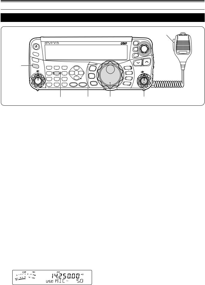
TRANSMISSION
we
HF/50MHz ALL MODE TRANSCEIVER TS-480
PF |
|
|
|
|
|
|
|
ANT |
1/2 |
|
|
|
|
|
|
ATT/PRE |
|
|
|
|
|
|
|
AT |
1 REC |
2 REC |
3 REC |
|
|
|
|
CH1 |
CH2 |
CH3 |
DNL |
|
MODE |
||
|
|
NAR |
|||||
AF |
|
SQL 4 TX MONI |
5 RF.G |
6 DELAY |
|
|
|
|
NR |
FIL |
F.LOCK |
||||
|
|
PWR |
MIC |
KEY |
|||
|
|
|
|||||
|
|
7 |
8 |
9 |
BC |
|
MENU |
|
|
NB/T |
VOX |
PROC |
CW.T |
|
|
|
|
|
|
|
|||
|
|
CLR |
0 OFF |
|
STEP |
SG.SEL |
MHz |
|
|
|
|
|
|||
|
|
MTR |
AGC |
ENT |
FINE |
SCAN |
|
|
|
|
|||||
ro t q
ti
CL
XIT
RIT
M.IN |
TF-SET |
|
QMI |
||
M VFO |
MULTI |
IF |
QMR |
SHIFT |
|
|
|
|
M/V |
|
|
A / B |
|
|
SPLIT |
|
|
A=B |
|
|
u
qTurn the Tuning control to tune in a desired station or to select an unused frequency.
•If you are operating the TS-480HX transceiver without the AT-300 antenna tuner, continue to step 4.
wPress [AT] momentarily.
• “ATsT” appears.
ePress and hold [AT] to start tuning the antenna tuner (TS-480SAT or TS-480HX with the AT-300 antenna tuner).
•“RtATsT” starts blinking and the LED above the [MODE] key turns red.
•Tuning should be completed in under
20 seconds, then a morse code “T” (a long single beep) sounds and “ATsT” stops blinking.
•If tuning is not completed within 20 seconds, error beeps sound. Press [AT] to stop the error beeps and quit tuning. Check your antenna system before continuing. If you do not press [AT], tuning will continue for approximately 60 seconds.
Note:
You will hear a lot of clicking sounds coming from the transceiver or external antenna tuner while the antenna tuner is trying to tune the antenna. This is simply the relay switches turning ON and OFF.
When the TS-480HX transceiver is used with the AT-300 external antenna tuner, the TX output power is automatically reduced to 100 watts (AM: 25 watts).
rWith LSB, USB, or AM selected, press
[MIC/ 5/ RF.G] to adjust the Microphone Gain.
• “MIC -- 50” appears.
tPress Mic [PTT].
• The LED lights red.
yBegin speaking into the microphone in your normal tone of voice.
uLSB/ USB: While speaking into the microphone, adjust the MULTI control so that the ALC meter reflects according to your voice level.
AM: While speaking into the microphone, adjust the MULTI control so that the power meter slightly reflects to your voice level.
FM: Skip this step.
iWhen you finish speaking, release Mic [PTT] to return to receive mode.
oPress [MIC/ 5/ RF.G] to finish adjusting the Microphone Gain.
Note: If desired, access Menu No. 44 {page 27} to adjust the Microphone Gain for FM mode.
This completes your introduction to the TS-480 transceiver, but there is a great deal more to know. “OPERATING BASICS” {page 18} and the following chapters explain all the functions of this transceiver, starting with the most basic, commonly-used functions.
•With FM selected, skip this step.
9
GETTING ACQUAINTED
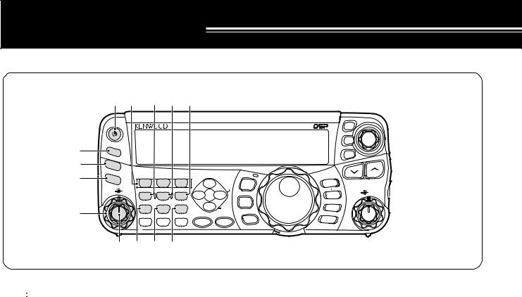
REMOTE CONTROL PANEL
|
q u |
i o !0 |
|
|
|
|
|
|||||
|
|
|
|
|
|
|
|
HF/50MHz ALL MODE TRANSCEIVER TS-480 |
|
CL |
|
|
|
|
|
|
|
|
|
|
|
|
|
XIT |
|
w |
PF |
|
|
|
|
|
|
|
|
RIT |
|
|
|
ANT |
1/2 |
|
|
|
|
|
|
|
|
|
|
e |
|
|
|
|
|
|
|
|
|
|
||
ATT/PRE |
|
|
|
|
|
|
|
|
|
|
||
r |
AT |
|
1 REC |
2 REC |
3 REC |
|
|
|
M.IN |
TF-SET |
||
|
CH1 |
CH2 |
CH3 |
DNL |
|
MODE |
QMI |
|||||
|
|
|
|
|
||||||||
|
|
|
|
NAR |
|
IF |
||||||
|
AF |
|
SQL |
4 TX MONI |
5 RF.G |
6 DELAY |
|
|
M VFO |
|
||
|
|
|
|
F.LOCK |
MULTI |
|||||||
|
|
|
|
PWR |
MIC |
KEY |
NR |
FIL |
QMR |
SHIFT |
||
|
|
|
|
|
|
|
||||||
|
|
|
|
7 |
8 |
9 |
BC |
|
MENU |
M/V |
|
|
t |
|
|
|
NB/T |
VOX |
PROC |
CW.T |
|
A / B |
|
|
|
|
|
|
CLR |
0 OFF |
|
STEP |
SG.SEL |
|
SPLIT |
|
|
|
|
|
|
|
MHz |
A=B |
|
|
|||||
|
|
|
|
MTR |
AGC |
ENT |
FINE |
SCAN |
|
|
||
|
|
|
|
|
|
|
|
|||||
|
|
y !1!2!3 |
|
|
|
|
|
|
||||
q [  ] (POWER) switch
Press and hold briefly to switch the transceiver power ON. Press again to switch the power OFF {page 18}.
w PF key
You can assign a function to this Programmable Function key. The default function is VOICE1.
To use the Voice Guide and Storage functions, the optional VGS-1 is required {page 64}.
e ATT/PRE/ ANT1/2 key
Press to cycle between receiver attenuator ON, preamplifier ON and OFF {pages 49, 61}.
Press and hold for 1 second, then release it to select either ANT 1 or ANT 2 {page 60}.
r AT
Press to activate the internal antenna tuner {page 60} or an external antenna tuner. Press and hold to start tuning the automatic antenna tuner.
t SQL control
Used for muting (“squelching”) the speaker, the head phones and the AF output on DATA (8-pin mini DIN connector) when no receive signal is present on the transceiver {page 19}.
y AF control
Turn to adjust the audio volume on the transceiver {page 18}.
u CH1/ 1/ REC, CH2/ 2/ REC, CH3/ 3/ REC key Press to play back the CW or voice messages (the VGS-1 is required) {page 40}. Press and hold to record the voice messages (the VGS-1 is required) {page 68} or CW messages that are associated with the internal electronic keyer {page 40}.
i PWR/ 4/ TX MONI key
Press to adjust the transmission output power. Press and hold to adjust the volume of the transmission signal monitor function {page 65}.
o MIC/ 5/ RF.G key
Press to adjust the microphone gain {page 27}. While the Speech Processor function is ON, press to adjust the Speech Processor output level {page 37}. Press and hold to adjust the receiver RF gain
{page 18}.
!0KEY/ 6/ DELAY key
Press to adjust the internal electronic keyer speed. Press and hold to adjust the VOX delay time {page 36} or Break-in time (Full Break-in/ Semi Break-in time) for CW mode {page 39}.
!1NB/T/ 7 key
Press to switch the Noise Blanker ON or OFF. Press and hold to adjust the Noise Blanker level {page 47}. In FM mode, press to turn the Tone function ON or OFF {page 32}. Press and hold to select a sub-audible tone for the Tone funtion {page 32}.
!2VOX/ 8 key
In voice mode, press to turn the VOX (VoiceOperated Transmit) function ON or OFF {page 36}. In CW mode, press to turn the Break-in function ON or OFF {page 39}. Press and hold to adjust the microphone input gain for VOX operation. The VOX icon appears when the VOX (Voice)/ Break-in (CW) function is active.
!3PROC/ 9 key
Press to turn the Speech Processor ON or OFF {page 37}. Press and hold to adjust the Speech Processor input level. The PROC icon appears when the Speech Processor function is ON.
10
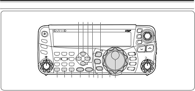
3 GETTING ACQUAINTED
!9@0@1@2@3
HF/50MHz ALL MODE TRANSCEIVER TS-480
PF |
|
|
|
|
|
|
|
|
|
ANT |
1/2 |
|
|
|
|
|
|
|
|
ATT/PRE |
|
|
|
|
|
|
|
|
|
AT |
|
1 REC |
2 REC |
3 REC |
|
|
|
M.IN |
|
|
CH1 |
CH2 |
CH3 |
DNL |
|
MODE |
QMI |
||
|
|
|
NAR |
||||||
AF |
|
SQL |
4 TX MONI 5 RF.G |
6 DELAY |
|
|
M VFO |
||
|
|
|
F.LOCK |
||||||
|
NR |
FIL |
QMR |
||||||
|
|
|
PWR |
MIC |
KEY |
||||
|
|
|
|
||||||
|
|
|
7 |
8 |
9 |
BC |
|
MENU |
M/V |
|
|
|
NB/T |
VOX |
PROC |
CW.T |
|
A / B |
|
|
|
|
|
|
|
SPLIT |
|||
|
|
|
CLR |
0 OFF |
|
STEP |
SG.SEL |
|
|
|
|
|
|
|
|
MHz |
A=B |
||
|
|
|
MTR AGC ENT FINE SCAN |
||||||
|
|
|
|
|
|||||
|
|
|
!4!5!6 !7 !8@4@5@6@7@8 |
|
|||||
CL
XIT
RIT
TF-SET
IF MULTI  SHIFT
SHIFT
!4MTR/ CLR key
Press to select the meter scales {page 20} or exit from, abort, or reset various functions. Press and hold to clear memory channels {page 54}.
!5AGC/ 0/ OFF key
Press to toggle the fast or slow response time for the Automatic Gain Control (AGC). Press and hold to switch the AGC OFF {page 35}.
!6ENT key
Press to enter your desired frequency using the keypad {page 34} or lock out memory channels from the scan list {page 54}.
!7FINE/ STEP key
Press to activate the Fine tuning function to allow more precise tuning {page 35}. Press and hold to select the frequency step size for the MULTI control {page 34}.
!8SCAN/ SG.SEL key
Press to start or stop the Scan function {page 56}. Press and hold to select a Scan group {page 59}.
!9NR key
Press to select the DSP Noise Reduction function, NR1, NR2 or OFF {page 47}. When the Noise Reduction function is turned ON, press and hold key to change the parameter of the Noise Reduction function {page 47}.
@0DNL key
Press to turn the DNL (Digital Noise Limiter) function ON or OFF. The “DNL” icon appears when it is ON. Press and hold the key to change the level of DNL function {page 47}.
@1FIL/ NAR key
Press to configure the low-cut and high-cut filter frequency for the DSP filter (AF). Press and hold to select the narrow IF filter if available {page 45}.
@2BC/ CW.T key
Press to select the DSP Beat Cancel funtion, BC1 (Beat Cancel 1), BC2 (Beat Cancel 2) or OFF
{page 47}. In CW mode, press to start the Auto Zerobeat in CW mode {page 29}.
@3LED
Lights red when the transceiver is transmitting, lights green when the transceiver is receiving signals, and turns OFF when the transceiver mutes with the squelch function.
@4MODE key
Press to change the operating mode pair. There are 4 pairs: USB/ LSB, CW/ CWR, FSK/ FSR, and AM/ FM. Press and hold for a second to toggle the mode within each pair: USB  LSB, CW
  CWR,
CWR,
FSK  FSR, or AM
  FM {page 19}.
@5MENU/ F.LOCK key
Press to enter Menu mode {page 22}. Press and hold to activate the Frequency Lock function {page 63}.
@6MHz key
Press to turn the MHz Up/ Down function ON or OFF. The MHz digit increases or decreases when you turn the MULTI control. Press and hold to change the increment/ decrement step value {page 34}.
@7Tuning control torque adjustment lever
The lever behind the Tuning control adjusts the control torque level; turn clockwise for light torque or counterclockwise for heavy torque.
@8Tuning control
Turn to select the desired frequency {page 19}. Use the convenient finger-tip cavity for continuous tuning.
11
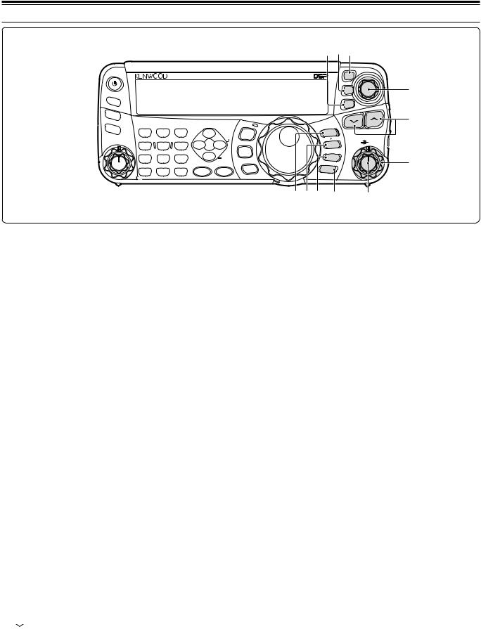
3 GETTING ACQUAINTED
#8#7#6
PF
ANT 1/2
ATT/PRE
AT
AF SQL
SQL
HF/50MHz ALL MODE TRANSCEIVER TS-480 |
CL |
XIT |
#9 |
RIT |
|
|
|
|
|
|
|
|
#5 |
1 REC |
2 REC |
3 REC |
|
|
|
M.IN |
TF-SET |
|
CH1 |
CH2 |
CH3 |
DNL |
|
MODE |
QMI |
||
NAR |
|
IF |
||||||
4 TX MONI |
5 RF.G |
6 DELAY |
|
|
M VFO |
|
||
|
|
|
|
|||||
PWR |
MIC |
KEY |
NR |
FIL |
F.LOCK |
QMR |
MULTI |
SHIFT |
|
|
|
||||||
7 |
8 |
9 |
BC |
|
MENU |
M/V |
|
|
NB/T |
VOX |
PROC |
CW.T |
|
A / B |
|
#4 |
|
|
|
|
SPLIT |
|
||||
CLR |
0 OFF |
|
STEP |
SG.SEL |
|
|
||
|
|
|
MHz |
A=B |
|
|
||
MTR |
AGC |
ENT |
FINE |
SCAN |
|
|
||
|
|
|
|
|||||
@9#0#1#2 #3
@9QMI/ M.IN key
Press to store data to the Quick Memory. Press and hold to store the current operating frequencies and other data to the Memory channel.
#0QMR/ MsVFO key
Press to recall data from the Quick Memory {page 55}. Press and hold to transfer the Memory Channel frequencies and other data to the VFO.
#1A/B / M/V key
Press to select either VFO A or VFO B {page 18}. Press and hold to toggle between Memory and VFO modes.
#2A=B/ SPLIT key
Press to duplicate the data in the currently selected VFO to the other VFO {page 35}. Press and hold to enter split-frequency operation which allows you to use different transmission and reception frequencies {page 30}.
#3MULTI control
In VFO mode, rotate to step the operating frequency up or down {page 34}. In Memory Channel mode, rotate to select a Memory Channel {page 51}.
Also, used for selecting Menu numbers when accessing the Menu mode {page 22} and as a selector to choose settings for various functions activated by Remote Control panel keys.
#4IF SHIFT control
Rotate to shift the center frequency of the IF passband either lower or higher, to remove interference {page 45}.
#5 /  key
key
#6CL key
Press to clear the RIT/ XIT frequency to zero {pages 35, 37}.
#7XIT key
Press to turn the XIT (Transmit Incremental Tuning) function ON or OFF {page 37}. When the XIT function is ON, the XIT icon appears.
#8RIT key
Press to turn the RIT (Receive Incremental Tuning) function ON or OFF {page 35}. When the RIT function is ON, the RIT icon appears.
#9RIT/ XIT control
When the RIT/ XIT function is ON, turn to adjust the offset frequency. The RIT/ XIT offset frequency appears on the sub-display {pages 35, 37}.
Normally, press to step through all the Amateur radio bands consecutively {page 19}. Also used to make selections from the Menu {page 22} and to check the Start and End frequencies of the Scan function {page 53}. When both the split-frequency and the frequency lock function are actived, press and hold to perform the TF-SET function {page 30}.
12
3 GETTING ACQUAINTED
LCD DISPLAY
q w |
e |
r t y u i o!0!1 !2 !3!4!5!6 !7!8!9 |
q METER
While receiving, serves as an S-meter to measure and display the received signal strength. While transmitting, serves as a power meter plus an ALC meter, an SWR meter, or a Speech Processor compression meter. The Peak Hold function holds each reading for approximately half a second.
w RtATsT
Appears while the internal antenna tuner {page 60} or an external antenna tuner is in-line for the operation.
e 1tANTs2
Either “1tANT” or “ANTs2” appears, depending on which antenna connector is selected for the operation {page 60}.
r ATT
Appears when the receiver’s attenuator (approx. 12 dB) is ON {pages 49, 61}.
t PRE
Appears when the receiver pre-amplifier (approx. 6 dB) is ON {page 49}.
y VOX
Appears when the VOX (Voice Operated Transmission) function is ON or the Break-in function is ON for the CW mode {pages 36, 39}.
u PROC
Appears when the Speech Processor function is ON {page 37}.
i MENU
Appears when configuring the parameters in the Menu mode {page 22}.
o 
Reserved for future updates.
!0
Appears while the Constant Recording function is working {page 69}.
!1NB
Appears when the Noise Blanker is ON {page 47}.
!2AGC OFF
“AGC - F” (fast) or “AGC” (slow) appears when the AGC (Automatic Gain Control) function is ON. “AGC OFF” appears when the AGC is OFF {page 35}.
!3NAR 2
“NAR” appears when the narrow IF filter is selected for the operating mode. If 2 optional IF filters are installed and the transceiver selects the secondary IF filter, “NAR 2” appears {page 45}.
!4MHz
Appears when the MHz Up/ Down mode using the MULTI control is ON {page 34}. It also appears when the Quick Menu function is ON {page 22}.
!5FINE
Appears when the Fine function is ON {page 35}.
!6
Appears when the selected Menu No. is in the Quick Menu list. It also appears when the transceiver is scanning the frequencies between the slow down frequency points {page 57}.
!7

Appears when the split-frequency operation is ON {page 30}.
!8
Appears when the Tuning control Lock function is ON {page 63}.
!9
Appears when the Frequency Lock function is ON {page 63}.
13

3 GETTING ACQUAINTED
|
|
#7 |
|
|
#6 |
|
|
#5 |
|
|
#4 |
@0@1@2@3@4@5@6@7@8@9 |
#0 |
#1#2#3 |
@0RtEQsT
“RtEQ” appears when the RX Equalizer function is ON {page 64}. “EQsT” appears when the TX Equalizer function is ON {page 38}.
@1tBCs2
“1tBC” or “BCs2” appears, as you select the DSP Beat Cancel 1 or Beat Cancel 2 {page 47}.
@21tNRs2
“1tNR” or “NRs2” appears, depending on whether DSP Noise Reduction 1 (Line Enhanced method) or Noise Reduction 2 (SPAC method) is selected {page 47}.
@3M.CH
Appears in Memory Recall mode {page 51}.
@4M.SCR
Appears in Memory Scroll mode {page 52}.
@5DNL
Appears when the Digital Noise Limiter function is ON {page 47}.
@6

Shows the Memory Channel number for the transceiver. In Menu mode, it displays the Menu No. In Quick Memory mode, it shows the Quick Memory number location (the Quick Memory number ranges from “0_” to “9_”) {page 55}.
@7


Displays a communication mode {page 19}.
@8AUTO
Appears when Auto Mode function is ON {page 61}.
@9


The transceiver operating frequency display. In Menu mode, it displays the parameters.
#0


In the normal operating mode, it displays the transceiver status and Menu item descriptions when necessary. While the RIT, XIT or SPLIT function is turned ON, it is used to display the frequency information for these functions {pages 35, 37}.
#1tAs
“tA” or “As” appears while VFO A is selected {pages 18, 30}. “A” appears while Menu A is being accessed in the Menu mode {page 22}.
#2tBs
“tB” or “Bs” appears while VFO B is selected {pages 18, 30}. “B” appears while Menu B is being accessed in the Menu mode {page 22}.
#3tMs
“tM” or “Ms” appears while a simplex memory channel is selected {page 50}.
#4RIT
Appears when Receive Incremental Tuning function is ON {page 35}.
#5XIT
Appears when Transmit Incremental Tuning function is ON {page 37}.
#6CT
“T” appears when the Tone function is ON {page 32}. “CT” appears when the CTCSS (Continuous Tone Coded Squelch System) is ON {page 33}.
#7PC
Appears when the transceiver is being controlled by a PC {page 67}.
14
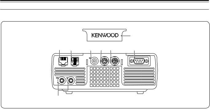
3 GETTING ACQUAINTED
TX/ RX UNIT
|
|
|
|
i |
q w |
e |
r |
t |
y |
|
EXT.SP |
DATA |
REMOTE |
|
MIC |
PANEL |
|
|
COM |
PADDLE KEY
u
q MIC connector
Connect a cable from the supplied microphone to this connector {page 6}.
w PANEL connector
Connect a cable from the Remote Control panel to this connector {page 6}.
e EXT.SP jack
Mate with a 3.5 mm (1/8"), 2-conductor (mono) plug for connecting an external speaker {page 7}.
r DATA connector
Mates with a 6-pin male DIN connector for connecting various accessory equipment, such as an external TNC/ MCP or a RTTY terminal {pages 77, 78}.
t REMOTE connector
Mates with a 6-pin male mini DIN connector for connecting an HF/ 50 MHz linear amplifier {page 77}.
y COM connector
Mates with a DB-9 female connector for connecting a computer via one of its serial communication (COM) ports {page 67}. Also used with the Quick Data Transfer function {pages 66, 76} and DX PacketCluster Tune function {pages 72, 79}.
u PADDLE and KEY jacks
The PADDLE jack mates with a 6.3 mm (1/4") 3-conductor plug for connecting a keyer paddle to the internal electronic keyer. The KEY jack mates with a 3.5 mm (1/8") 2-conductor plug for connecting an external key for CW operation. Refer to “Keys for CW (PANEL and KEY)” {page 7} before using these jacks.
i Plastic cover
If the EXT.SP jack, DATA connector and REMOTE connector are not used, attach this cover to protect the connectors from dust.
15
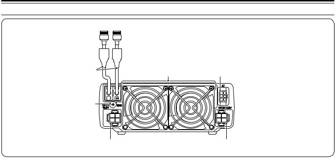
3 GETTING ACQUAINTED
ANT 2 ANT 1
q |
e |
r |
|
w
t |
y |
q ANT 1 and ANT 2 connectors
Connect your primary HF/ 50 MHz antenna to ANT 1 connector. If you are using 2 antennas for the HF/ 50 MHz band, connect the secondary antenna to the ANT 2 connector.
w GND post
Connect a heavy gauge wire or copper strap between the ground post and the nearest earth ground or vehicle body {pages 2, 4}.
e Cooling Fans
The TS-480SAT is equipped with 1 cooling fan.
The TS-480HX is equipped with 2 cooling fans.
Air flows in from these fans.
r AT connector
Mates with the connecter from the cable supplied with the AT-300 external antenna tuner. Refer to the instruction manual supplied with the tuner for more information.
t DC 1 13.8 V DC power input connector
Connect a primary 13.8 V DC power source to this connector {pages 2, 3}. Use the DC cable supplied with the transceiver.
yDC 2 13.8 V DC power input connector (TS-480HX only)
You must connect a secondary 13.8 V DC power source to this connector in order to transmit {pages 2, 3}. Use the cable supplied with the transceiver. If no DC power source is available on this connector, you cannot transmit at any output power. However, you can still receive {page 18}.
16
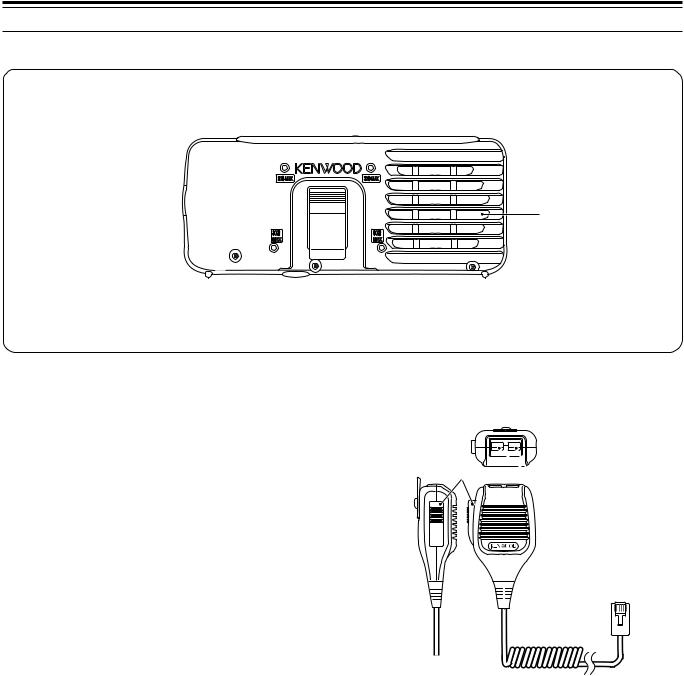
3 GETTING ACQUAINTED
REMOTE CONTROL PANEL (REAR)
q
qSpeaker
When the headphones are connected, the speaker mutes.
MICROPHONE
If you wish to use a commercially available 3rd party angle or mount, there are 4 screw holes available on the rear of the Remote Control panel so that you can mount it to the angle or mount. Use 3 mm x 8 mm tapping screws to mount the panel securely to the angle or mount. (The tapping screws are not supplied).
DWN UP
q w
w
PTT |
q PTT (Push-to-Talk) switch
The transceiver is placed in Transmission mode when this non-locking switch is held down. Releasing the switch returns the transceiver to Reception mode.
w UP/ DWN keys
Use these keys to step the VFO frequency, Memory Channels, or Menu selections up and down.
Press and hold these keys to continuously change the settings.
17
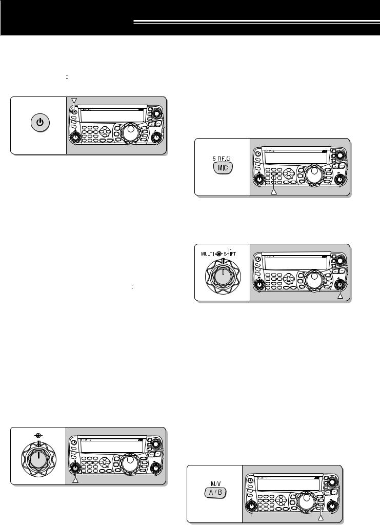
OPERATING BASICS
SWITCHING POWER ON/ OFF
1Switch the DC power supply(s) ON if you are using a DC power supply(s).
2Press and hold [  ] (POWER) briefly to switch the transceiver ON.
|
|
|
|
|
HF/50MHz ALL MODE TRANSCEIVER TS-480 |
|
CL |
|
|
|
|
|
|
|
|
|
|
XIT |
|
PF |
|
|
|
|
|
|
|
RIT |
|
ANT 1/2 |
|
|
|
|
|
|
|
|
|
|
|
|
|
|
|
|
|
|
|
ATT/PRE |
|
|
|
|
|
|
|
|
|
AT |
1 REC |
2 REC |
3 REC |
|
|
|
M.IN |
TF-SET |
|
CH1 |
CH2 |
CH3 |
DNL |
|
MODE |
QMI |
|||
|
NAR |
||||||||
AF |
SQL 4 TX MONI |
5 RF.G |
6 DELAY |
|
M VFO |
|
IF |
||
|
|
F.LOCK |
MULTI |
||||||
|
PWR |
MIC |
KEY |
NR |
FIL |
QMR |
SHIFT |
||
|
7 |
8 |
9 |
BC |
|
MENU |
M/V |
|
|
|
NB/T |
VOX |
PROC |
CW.T |
|
A / B |
|
|
|
|
CLR |
0 OFF |
|
STEP |
SG.SEL |
MHz |
SPLIT |
|
|
|
MTR |
AGC |
ENT |
FINE |
SCAN |
A=B |
|
|
|
•Do not press the switch for more than approximately 2 seconds; the transceiver will be switched OFF.
•TS-480HX only: If “RX ONLY” appears on the sub-display upon power up, confirm that two DC cable connectors are securely connected to the DC-1 and DC-2 connectors. When this warning message appears, you can receive signals as usual but you cannot transmit even if you decrease the output power. “TWIN PWR” appears when two DC power cables are connected to the DC-1 and DC-2 connectors.
•Upon power up, “HELLO” appears on the main display, followed by the selected frequency and other indicators.
3 To switch the transceiver OFF, press [  ] (POWER) again.
4Switch the DC power supply(s) OFF.
•You may skip step 3. After switching the transceiver ON, you can switch it OFF or ON using only the power switch of the DC power supply(s). The transceiver remembers the information of the POWER switch position when the DC power source is switched OFF.
ADJUSTING VOLUME
AF (AUDIO FREQUENCY) GAIN
Turn the AF control clockwise to increase the audio level and counterclockwise to decrease the level.
AF |
SQL |
|
|
|
|
|
|
|
|
|
|
|
|
|
|
|
HF/50MHz ALL MODE TRANSCEIVER TS-480 |
|
CL |
|
|
|
|
|
|
|
|
|
|
|
XIT |
|
|
PF |
|
|
|
|
|
|
|
RIT |
|
|
ANT 1/2 |
|
|
|
|
|
|
|
|
|
|
|
|
|
|
|
|
|
|
|
|
|
ATT/PRE |
|
|
|
|
|
|
|
|
|
|
AT |
1 REC |
2 REC |
3 REC |
|
|
|
M.IN |
TF-SET |
|
|
CH1 |
CH2 |
CH3 |
DNL |
|
MODE |
QMI |
|||
|
|
NAR |
||||||||
|
AF |
SQL 4 TX MONI |
5 RF.G |
6 DELAY |
|
M VFO |
|
IF |
||
|
|
|
F.LOCK |
MULTI |
||||||
|
|
PWR |
MIC |
KEY |
NR |
FIL |
QMR |
SHIFT |
||
|
|
7 |
8 |
9 |
BC |
|
MENU |
M/V |
|
|
|
|
NB/T |
VOX |
PROC |
CW.T |
|
A / B |
|
|
|
|
|
CLR |
0 OFF |
|
STEP |
SG.SEL |
MHz |
SPLIT |
|
|
|
|
MTR |
AGC |
ENT |
FINE |
SCAN |
A=B |
|
|
|
Note: The position of the AF control does not affect the volume of beeps caused by pressing keys nor the CW TX sidetone. The audio level for Digital mode operation is also independent of the AF control setting.
RF (RADIO FREQUENCY) GAIN
The RF gain is normally configured to the maximum level regardless of the operating modes. The transceiver has been configured to the maximum level at the factory. However, you may decrease the RF gain slightly when you have trouble hearing the desired signal because of excessive atmospheric noise or interference from other stations. First, take note of the peak S-meter reading of the desired signal.
1 Press [MIC/ RF.G] (1 s).
|
|
|
|
|
HF/50MHz ALL MODE TRANSCEIVER TS-480 |
|
CL |
|
|
|
|
|
|
|
|
|
|
XIT |
|
PF |
|
|
|
|
|
|
|
RIT |
|
ANT 1/2 |
|
|
|
|
|
|
|
|
|
|
|
|
|
|
|
|
|
|
|
ATT/PRE |
|
|
|
|
|
|
|
|
|
AT |
1 REC |
2 REC |
3 REC |
|
|
|
M.IN |
TF-SET |
|
CH1 |
CH2 |
CH3 |
DNL |
|
MODE |
QMI |
|||
|
NAR |
||||||||
AF |
SQL 4 TX MONI |
5 RF.G |
6 DELAY |
|
|
F.LOCK |
M VFO |
MULTI |
IF |
|
PWR |
MIC |
KEY |
NR |
FIL |
QMR |
SHIFT |
||
|
|
|
|
||||||
|
7 |
8 |
9 |
BC |
|
MENU |
M/V |
|
|
|
NB/T |
VOX |
PROC |
CW.T |
|
A / B |
|
|
|
|
CLR |
0 OFF |
|
STEP |
SG.SEL |
MHz |
SPLIT |
|
|
|
MTR |
AGC |
ENT |
FINE |
SCAN |
A=B |
|
|
|
•The current RF gain level appears on the sub-display (0: minimum ~ 100: maximum).
2Turn the MULTI control counterclockwise until the S-meter reads the peak value that you noted.
|
|
|
|
|
HF/50MHz ALL MODE TRANSCEIVER TS-480 |
|
CL |
|
|
|
|
|
|
|
|
|
|
XIT |
|
PF |
|
|
|
|
|
|
|
RIT |
|
ANT 1/2 |
|
|
|
|
|
|
|
|
|
ATT/PRE |
|
|
|
|
|
|
|
|
|
AT |
1 REC |
2 REC |
3 REC |
|
|
|
M.IN |
TF-SET |
|
|
CH1 |
CH2 |
CH3 |
DNL |
NAR |
MODE |
QMI |
||
AF |
SQL 4 TX MONI |
5 RF.G |
6 DELAY |
|
M VFO |
|
IF |
||
|
|
F.LOCK |
MULTI |
||||||
|
PWR |
MIC |
KEY |
NR |
FIL |
QMR |
SHIFT |
||
|
|
|
|
||||||
|
7 |
8 |
9 |
BC |
|
MENU |
M/V |
|
|
|
NB/T |
VOX |
PROC |
CW.T |
|
A / B |
|
|
|
|
CLR |
0 OFF |
|
STEP |
SG.SEL |
MHz |
SPLIT |
|
|
|
MTR |
AGC |
ENT |
FINE |
SCAN |
A=B |
|
|
|
•Signals that are weaker than this level will be attenuated and reception of the station will become easier.
Depending on the type and gain of your antenna, and the condition of the band, adjust the RF gain. When using FM mode, always adjust the RF gain to the maximum level.
SELECTING VFO A OR VFO B
Two VFOs are available for controlling the frequency on the transceiver. Each VFO (VFO A and VFO B) works independently so that a different frequency and mode can be selected. For example, when SPLIT operation is activated, VFO A is used for reception and VFO B is used for transmission. The opposite combination is also possible.
Press [A/B / M/V] to toggle between VFO A and B.
|
|
|
|
|
HF/50MHz ALL MODE TRANSCEIVER TS-480 |
|
CL |
|
|
|
|
|
|
|
|
|
|
XIT |
|
PF |
|
|
|
|
|
|
|
RIT |
|
ANT 1/2 |
|
|
|
|
|
|
|
|
|
|
|
|
|
|
|
|
|
|
|
ATT/PRE |
|
|
|
|
|
|
|
|
|
AT |
1 REC |
2 REC |
3 REC |
|
|
|
M.IN |
TF-SET |
|
CH1 |
CH2 |
CH3 |
DNL |
|
MODE |
QMI |
|||
|
NAR |
||||||||
AF |
SQL 4 TX MONI |
5 RF.G |
6 DELAY |
|
M VFO |
|
IF |
||
|
|
F.LOCK |
MULTI |
||||||
|
PWR |
MIC |
KEY |
NR |
FIL |
QMR |
SHIFT |
||
|
7 |
8 |
9 |
BC |
|
MENU |
M/V |
|
|
|
NB/T |
VOX |
PROC |
CW.T |
|
A / B |
|
|
|
|
CLR |
0 OFF |
|
STEP |
SG.SEL |
MHz |
SPLIT |
|
|
|
MTR |
AGC |
ENT |
FINE |
SCAN |
A=B |
|
|
|
•“tA” or “tB” appears to indicate which VFO is
selected.
18
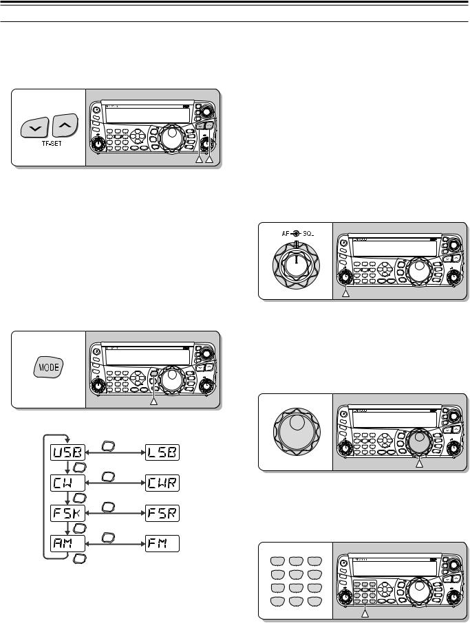
SELECTING A BAND
Press [ ]/ [
]/ [ ] to select your desired band.
•Holding down either key changes the bands continuously.
|
|
|
|
|
HF/50MHz ALL MODE TRANSCEIVER TS-480 |
|
CL |
|
|
|
|
|
|
|
|
|
|
XIT |
|
PF |
|
|
|
|
|
|
|
RIT |
|
ANT 1/2 |
|
|
|
|
|
|
|
|
|
|
|
|
|
|
|
|
|
|
|
ATT/PRE |
|
|
|
|
|
|
|
|
|
AT |
1 REC |
2 REC |
3 REC |
|
|
|
M.IN |
TF-SET |
|
CH1 |
CH2 |
CH3 |
DNL |
|
MODE |
QMI |
|||
|
NAR |
||||||||
AF |
SQL 4 TX MONI |
5 RF.G |
6 DELAY |
|
M VFO |
|
IF |
||
|
|
F.LOCK |
MULTI |
||||||
|
PWR |
MIC |
KEY |
NR |
FIL |
QMR |
SHIFT |
||
|
7 |
8 |
9 |
BC |
|
MENU |
M/V |
|
|
|
NB/T |
VOX |
PROC |
CW.T |
|
A / B |
|
|
|
|
CLR |
0 OFF |
|
STEP |
SG.SEL |
MHz |
SPLIT |
|
|
|
MTR |
AGC |
ENT |
FINE |
SCAN |
A=B |
|
|
|
SELECTING A MODE
Press [MODE] to cycle through the 4 mode pairs: USB/ LSB, CW/ CWR, FSK/ FSR, and AM/ FM. Each time you press [MODE], the mode display cycles USB or LSB, CW or CWR, FSK or FSR, FM or AM. To select the other mode on each pair, press [MODE] (1 s). For example, to select “LSB” while “USB” is visible, press [MODE] (1 s). “USB” changes to “LSB”. Press [MODE] (1 s) again to go back to “LSB” from “USB”. The following illustration describes how to access each mode with the [MODE] key.
|
|
|
|
|
HF/50MHz ALL MODE TRANSCEIVER TS-480 |
|
CL |
|
|
|
|
|
|
|
|
|
|
XIT |
|
PF |
|
|
|
|
|
|
|
RIT |
|
ANT 1/2 |
|
|
|
|
|
|
|
|
|
|
|
|
|
|
|
|
|
|
|
ATT/PRE |
|
|
|
|
|
|
|
|
|
AT |
1 REC |
2 REC |
3 REC |
|
|
|
M.IN |
TF-SET |
|
CH1 |
CH2 |
CH3 |
DNL |
|
MODE |
QMI |
|||
|
NAR |
||||||||
AF |
SQL 4 TX MONI |
5 RF.G |
6 DELAY |
|
M VFO |
|
IF |
||
|
|
F.LOCK |
MULTI |
||||||
|
PWR |
MIC |
KEY |
NR |
FIL |
QMR |
SHIFT |
||
|
7 |
8 |
9 |
BC |
|
MENU |
M/V |
|
|
|
NB/T |
VOX |
PROC |
CW.T |
|
A / B |
|
|
|
|
CLR |
0 OFF |
|
STEP |
SG.SEL |
MHz |
SPLIT |
|
|
|
MTR |
AGC |
ENT |
FINE |
SCAN |
A=B |
|
|
|
MODE (1 s)
MODE
MODE (1 s)
MODE
MODE (1 s)
MODE
MODE (1 s)
MODE
Access Menu No. 02 then press [ ] to select “on” to turn the Auto Mode selection ON. When it is ON, “AUTO” appears. As a default setting, if you change the frequency above or below 9.5 MHz, the transceiver automatically switches modes; LSB for frequencies under 9.5 MHz and USB for frequencies equal to or over 9.5 MHz. You can further add the frequency table data to change the mode automatically {page 61}.
4 OPERATING BASICS
ADJUSTING SQUELCH
The purpose of the Squelch is to mute the speaker when no signals are present. With the squelch level correctly set, you will hear sound only while actually receiving signals. The higher the selected squelch level, the stronger the signals must be to receive. The appropriate squelch level depends on the ambient RF noise conditions.
Turn the SQL control when there are no signals present to select the squelch level at which the background noise is just eliminated; the green LED will turn off. Many ham operators prefer leaving the SQL control fully counterclockwise unless operating on a full-carrier mode such as FM. The squelch level for the main transceiver is preset at the factory to approximately the 9 o’clock position for FM and 11 o’clock for SSB and AM.
|
|
|
|
|
HF/50MHz ALL MODE TRANSCEIVER TS-480 |
|
CL |
|
|
|
|
|
|
|
|
|
|
XIT |
|
PF |
|
|
|
|
|
|
|
RIT |
|
ANT 1/2 |
|
|
|
|
|
|
|
|
|
ATT/PRE |
|
|
|
|
|
|
|
|
|
AT |
1 REC |
2 REC |
3 REC |
|
|
|
M.IN |
TF-SET |
|
|
CH1 |
CH2 |
CH3 |
DNL |
NAR |
MODE |
QMI |
||
AF |
SQL 4 TX MONI |
5 RF.G |
6 DELAY |
|
M VFO |
|
IF |
||
|
|
F.LOCK |
MULTI |
||||||
|
PWR |
MIC |
KEY |
NR |
FIL |
QMR |
SHIFT |
||
|
|
|
|
||||||
|
7 |
8 |
9 |
BC |
|
MENU |
M/V |
|
|
|
NB/T |
VOX |
PROC |
CW.T |
|
A / B |
|
|
|
|
CLR |
0 OFF |
|
STEP |
SG.SEL |
MHz |
SPLIT |
|
|
|
MTR |
AGC |
ENT |
FINE |
SCAN |
A=B |
|
|
|
SELECTING A FREQUENCY
Turn the Tuning control clockwise or press Mic [UP] to increase the frequency. Turn the Tuning control counterclockwise or press Mic [DWN] to decrease the frequency.
|
|
|
|
|
HF/50MHz ALL MODE TRANSCEIVER TS-480 |
|
CL |
|
|
|
|
|
|
|
|
|
|
XIT |
|
PF |
|
|
|
|
|
|
|
RIT |
|
ANT 1/2 |
|
|
|
|
|
|
|
|
|
ATT/PRE |
|
|
|
|
|
|
|
|
|
AT |
1 REC |
2 REC |
3 REC |
|
|
|
M.IN |
TF-SET |
|
|
CH1 |
CH2 |
CH3 |
DNL |
NAR |
MODE |
QMI |
||
AF |
SQL 4 TX MONI |
5 RF.G |
6 DELAY |
|
M VFO |
|
IF |
||
|
PWR |
MIC |
KEY |
NR |
FIL |
F.LOCK |
QMR |
MULTI |
SHIFT |
|
|
|
|
||||||
|
7 |
8 |
9 |
BC |
|
MENU |
M/V |
|
|
|
NB/T |
VOX |
PROC |
CW.T |
|
A / B |
|
|
|
|
CLR |
0 OFF |
|
STEP |
SG.SEL |
MHz |
SPLIT |
|
|
|
MTR |
AGC |
ENT |
FINE |
SCAN |
A=B |
|
|
|
You may prefer directly entering a frequency using the numeric keypad if the desired frequency is far from the current frequency. Press [ENT], then press the numeric keys as necessary. For details, refer to “Direct Frequency Entry” {page 34}.
1 REC |
2 REC |
3 REC |
|
|
|
|
|
|
|
|
|
CH1 |
CH2 |
CH3 |
|
|
|
|
|
HF/50MHz ALL MODE TRANSCEIVER TS-480 |
|
CL |
|
4 TX MONI |
5 RF.G |
6 DELAY |
|
|
|
|
|
|
|
|
XIT |
PF |
|
|
|
|
|
|
|
|
|||
|
MIC |
KEY |
|
|
|
|
|
|
|
RIT |
|
PWR |
ANT 1/2 |
|
|
|
|
|
|
|
|||
|
|
|
|
|
|
|
|
||||
ATT/PRE |
|
|
|
|
|
|
|
|
|||
7 |
8 |
9 |
AT |
1 REC |
2 REC |
3 REC |
|
|
|
M.IN |
TF-SET |
NB/T |
VOX |
PROC |
|
CH1 |
CH2 |
CH3 |
DNL |
NAR MODE |
QMI |
||
|
PWR |
MIC |
KEY |
NR |
QMR |
IF |
|||||
|
FIL |
|
|||||||||
|
|
|
AF SQL 4 TX MONI 5 RF.G |
6 DELAY |
|
|
F.LOCK |
M VFO |
|||
|
|
|
|
|
|
|
|
|
|
MULTI SHIFT |
|
CLR |
0 OFF |
|
|
7 |
8 |
9 |
BC |
|
MENU |
M/V |
|
|
|
NB/T |
VOX |
PROC |
CW.T |
|
A / B |
|
|||
MTR |
AGC |
ENT |
|
CLR |
0 OFF |
|
STEP |
SG.SEL |
MHz |
SPLIT |
|
|
MTR |
AGC |
ENT |
FINE |
SCAN |
A=B |
|
||||
This transceiver provides many other methods for quickly selecting a frequency. For further information, refer to “SELECTING YOUR FREQUENCY”
{page 34}.
19
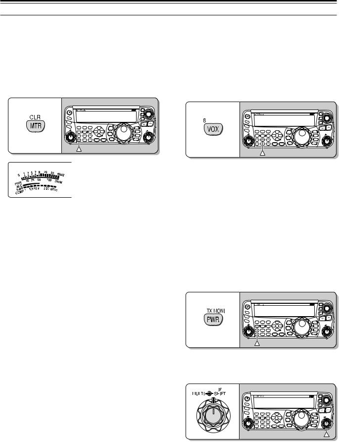
4 OPERATING BASICS
MULTI-FUNCTION METER
The multi-function meter measures the parameters in the table below. The S-meter scale appears when the transceiver is in reception mode, and the PWR meter appears when it is in transmission mode. Each time you press [MTR/ CLR], it cycles between the ALC, SWR, and COMP meters. Peak readings for the S-meter, ALC, SWR, COMP, and PWR functions are held momentarily.
|
|
|
|
|
HF/50MHz ALL MODE TRANSCEIVER TS-480 |
|
CL |
|
|
|
|
|
|
|
|
|
|
XIT |
|
PF |
|
|
|
|
|
|
|
RIT |
|
ANT 1/2 |
|
|
|
|
|
|
|
|
|
|
|
|
|
|
|
|
|
|
|
ATT/PRE |
|
|
|
|
|
|
|
|
|
AT |
1 REC |
2 REC |
3 REC |
|
|
|
M.IN |
TF-SET |
|
CH1 |
CH2 |
CH3 |
DNL |
|
MODE |
QMI |
|||
|
NAR |
||||||||
AF |
SQL 4 TX MONI |
5 RF.G |
6 DELAY |
|
M VFO |
|
IF |
||
|
|
F.LOCK |
MULTI |
||||||
|
PWR |
MIC |
KEY |
NR |
FIL |
QMR |
SHIFT |
||
|
7 |
8 |
9 |
BC |
|
MENU |
M/V |
|
|
|
NB/T |
VOX |
PROC |
CW.T |
|
A / B |
|
|
|
|
CLR |
0 OFF |
|
STEP |
SG.SEL |
MHz |
SPLIT |
|
|
|
MTR |
AGC |
ENT |
FINE |
SCAN |
A=B |
|
|
|
TRANSMITTING
For voice communications, press and hold Mic [PTT], then speak into the microphone in your normal tone of voice. When you finish speaking, release Mic [PTT] to receive.
To transmit CW, press [VOX/ 8] to switch the Break-in function ON. “VOX” appears. Close the key or keyer paddle. Connect a key or keyer paddle {pages 7, 15}, then select CW using [MODE] {page 19}.
|
|
|
|
|
HF/50MHz ALL MODE TRANSCEIVER TS-480 |
|
CL |
|
|
|
|
|
|
|
|
|
|
XIT |
|
PF |
|
|
|
|
|
|
|
RIT |
|
ANT 1/2 |
|
|
|
|
|
|
|
|
|
|
|
|
|
|
|
|
|
|
|
ATT/PRE |
|
|
|
|
|
|
|
|
|
AT |
1 REC |
2 REC |
3 REC |
|
|
|
M.IN |
TF-SET |
|
CH1 |
CH2 |
CH3 |
DNL |
|
MODE |
QMI |
|||
|
NAR |
||||||||
AF |
SQL 4 TX MONI |
5 RF.G |
6 DELAY |
|
M VFO |
|
IF |
||
|
|
F.LOCK |
MULTI |
||||||
|
PWR |
MIC |
KEY |
NR |
FIL |
QMR |
SHIFT |
||
|
7 |
8 |
9 |
BC |
|
MENU |
M/V |
|
|
|
NB/T |
VOX |
PROC |
CW.T |
|
A / B |
|
|
|
|
CLR |
0 OFF |
|
STEP |
SG.SEL |
MHz |
SPLIT |
|
|
|
MTR |
AGC |
ENT |
FINE |
SCAN |
A=B |
|
|
|
|
Multi-function meter |
|
|
|
|
Meter |
What Is Measured? |
|
|
|
|
S |
Strength of received signals |
|
|
|
|
PWR |
Transmission output power |
|
|
|
|
ALC |
Automatic level control status |
|
|
|
|
SWR |
Antenna system standing wave ratio |
|
|
|
|
COMP |
Speech compression level when using |
|
the Speech Processor {page 37} |
||
|
||
|
|
Note:
The COMP meter functions only when the Speech Processor is ON for SSB, FM, or AM mode.
Peak Hold readings cannot be deactivated.
The S-meter responds differently in FM mode, compared to other modes. This is not a malfunction.
For a detailed explanation on transmitting, refer to “BASIC COMMUNICATIONS”, beginning on page 27.
SELECTING TRANSMISSION POWER
It is wise to select a lower transmission power if communication is still reliable. This lowers the risk of interfering with others on the band. When operating from battery power, selecting a lower transmission power allows you more operating time before recharging is necessary. This transceiver allows you to change the transmission power even while transmitting.
1Press [PWR/ 4/ TX MONI].
• The current transmission power appears.
|
|
|
|
|
|
HF/50MHz ALL MODE TRANSCEIVER TS-480 |
|
CL |
|
|
4 |
|
|
|
|
|
|
|
|
XIT |
|
PF |
|
|
|
|
|
|
|
RIT |
|
|
|
ANT 1/2 |
|
|
|
|
|
|
|
|
|
|
ATT/PRE |
|
|
|
|
|
|
|
|
|
|
AT |
1 REC |
2 REC |
3 REC |
|
|
|
M.IN |
TF-SET |
|
|
|
CH1 |
CH2 |
CH3 |
DNL |
NAR |
MODE |
QMI |
||
|
AF |
SQL 4 TX MONI |
5 RF.G |
6 DELAY |
|
|
F.LOCK |
M VFO |
MULTI |
IF |
|
|
PWR |
MIC |
KEY |
NR |
FIL |
QMR |
SHIFT |
||
|
|
|
|
|
||||||
|
|
7 |
8 |
9 |
BC |
|
MENU |
M/V |
|
|
|
|
NB/T |
VOX |
PROC |
CW.T |
|
A / B |
|
|
|
|
|
CLR |
0 OFF |
|
STEP |
SG.SEL |
MHz |
SPLIT |
|
|
|
|
MTR |
AGC |
ENT |
FINE |
SCAN |
A=B |
|
|
|
2Turn the MULTI control counterclockwise to reduce the power or clockwise to increase the power.
|
|
|
|
|
HF/50MHz ALL MODE TRANSCEIVER TS-480 |
|
CL |
|
|
|
|
|
|
|
|
|
|
XIT |
|
PF |
|
|
|
|
|
|
|
RIT |
|
ANT 1/2 |
|
|
|
|
|
|
|
|
|
|
|
|
|
|
|
|
|
|
|
ATT/PRE |
|
|
|
|
|
|
|
|
|
AT |
1 REC |
2 REC |
3 REC |
|
|
|
M.IN |
TF-SET |
|
CH1 |
CH2 |
CH3 |
DNL |
|
MODE |
QMI |
|||
|
NAR |
||||||||
AF |
SQL 4 TX MONI |
5 RF.G |
6 DELAY |
|
M VFO |
|
IF |
||
|
|
F.LOCK |
MULTI |
||||||
|
PWR |
MIC |
KEY |
NR |
FIL |
QMR |
SHIFT |
||
|
7 |
8 |
9 |
BC |
|
MENU |
M/V |
|
|
|
NB/T |
VOX |
PROC |
CW.T |
|
A / B |
|
|
|
|
CLR |
0 OFF |
|
STEP |
SG.SEL |
MHz |
SPLIT |
|
|
|
MTR |
AGC |
ENT |
FINE |
SCAN |
A=B |
|
|
|
•The selectable range differs, depending on the transceiver model, the current band, and the mode.
3 Press [PWR/ 4/ TX MONI] to complete the setting.
Note: You may access Menu No. 21, and select “on” to change the step size from 5 W to 1 W {page 65}.
20
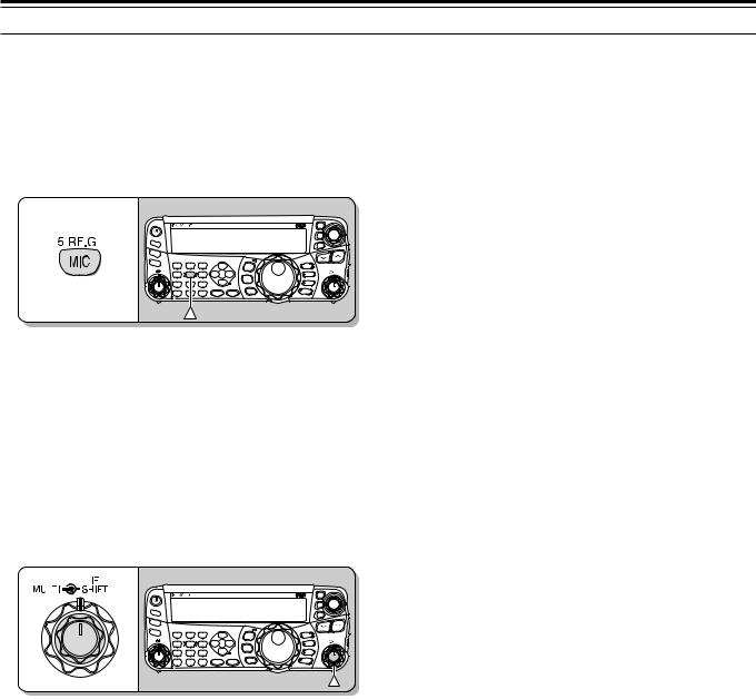
4 OPERATING BASICS
MICROPHONE GAIN
The microphone gain must be adjusted when SSB or AM mode is selected without using the speech processor {pages 27, 28}.
1Press [MIC/ 5/ RF.G].
•The current microphone gain level appears. The range is from 0 to 100 with a default of 50.
HF/50MHz ALL MODE TRANSCEIVER TS-480
PF |
|
|
|
|
|
|
|
ANT 1/2 |
|
|
|
|
|
|
|
ATT/PRE |
|
|
|
|
|
|
|
AT |
1 REC |
2 REC |
3 REC |
|
|
|
|
CH1 |
CH2 |
CH3 |
DNL |
|
MODE |
||
|
NAR |
||||||
AF |
SQL 4 TX MONI |
5 RF.G |
6 DELAY |
|
|||
NR |
FIL |
F.LOCK |
|||||
|
PWR |
MIC |
KEY |
||||
|
|
||||||
|
7 |
8 |
9 |
BC |
|
MENU |
|
|
NB/T |
VOX |
PROC |
CW.T |
|
||
|
CLR |
0 OFF |
|
STEP |
SG.SEL |
MHz |
|
|
MTR |
AGC |
ENT |
FINE |
SCAN |
M.IN QMI M VFO QMR
M/V
A / B
SPLIT A=B
CL
XIT
RIT
TF-SET
IF MULTI  SHIFT
SHIFT
2Press and hold Mic [PTT].
• The LED on the panel lights red.
3SSB: While speaking into the microphone, adjust the MULTI control so that the ALC meter reflects your voice level but does not exceed the ALC limit.
AM: While speaking into the microphone, adjust the MULTI control so that the power meter slightly reflects your voice level.
FM: Access Menu No. 44 and select “1” (Normal), “2” (Medium), or “3” (High) for the microphone gain if necessary {page 27}.
HF/50MHz ALL MODE TRANSCEIVER TS-480
PF |
|
|
|
|
|
|
|
ANT 1/2 |
|
|
|
|
|
|
|
ATT/PRE |
|
|
|
|
|
|
|
AT |
1 REC |
2 REC |
3 REC |
|
|
|
|
CH1 |
CH2 |
CH3 |
DNL |
|
MODE |
||
|
NAR |
||||||
AF |
SQL 4 TX MONI |
5 RF.G |
6 DELAY |
|
|||
NR |
FIL |
F.LOCK |
|||||
|
PWR |
MIC |
KEY |
||||
|
|
||||||
|
7 |
8 |
9 |
BC |
|
MENU |
|
|
NB/T |
VOX |
PROC |
CW.T |
|
||
|
|
|
|||||
|
CLR |
0 OFF |
|
STEP |
SG.SEL |
MHz |
|
|
MTR |
AGC |
ENT |
FINE |
SCAN |
||
|
|
M.IN QMI M VFO QMR
M/V
A / B
SPLIT A=B
CL
XIT
RIT
TF-SET
IF MULTI  SHIFT
SHIFT
4Release Mic [PTT] to return to receive.
•The LED lights green or turns off, depending on the SQL control setting.
Note: When using the MC-90 microphone with the MJ-88 in FM mode, select “3” (High) for the microphone gain. The microphone sensitivity is low in FM mode. This may cause insufficient modulation. For other microphones, select either “1” (Normal) or “2” (Medium).
21

MENU SETUP
WHAT IS A MENU?
Many functions on this transceiver are selected or configured via a software-controlled Menu, rather than through the physical controls of the transceiver. Once familiar with the Menu system, you will appreciate the versatility it offers. You can customize the various timings, settings, and programming functions on this transceiver to meet your needs without using many controls and switches.
QUICK MENU
Because the number of functions this transceiver provides is extraordinary, there are numerous items in each Menu. If you find accessing desired Menu Nos. to be too time consuming, use the Quick Menu to create your own customized, abbreviated Menu. You can then add those Menu Nos. which you frequently use, to the Quick Menu. Copying Menu Nos. to the Quick Menu has no effect on the Menu.
MENU A/ MENU B
This transceiver has 2 menus: Menu A and Menu B. These menus contain identical functions and can be configured independently. The transceiver, therefore, allows you to switch between 2 different environments quickly and easily. For example, you can configure Menu A for DXing and contesting while Menu B is for relaxed local ragchewing. By switching from Menu A to Menu B, you can instantly change the Menu configuration and key assignment to suit your current operating style. Or, 2 operators may share a single transceiver by dedicating one Menu to each operator. Both operators can always enjoy their own configuration.
MENU ACCESS
1Press [MENU/ F.LOCK].
•The Menu No. and setting appear on the display, and the explanation of the menu appears on the sub-display.
2Press [A/B / M/V] to select Menu A or Menu B.
•“A” or “B” appears, indicating which Menu is selected.
3Turn the MULTI control to select the desired Menu No.
•Each time you change the Menu No.,
a different scrolling message appears on the sub-display, describing the Menu No.
4Press [ ]/ [
]/ [ ], or Mic [UP]/ [DWN] to select a parameter.
PROGRAMMING THE QUICK MENU
1Press [MENU/ F.LOCK].
2Turn the MULTI control to select the desired Menu No.
3Press [QMI/ M.IN].
•An inverted star, “ ” appears, indicating that the Menu item has been added to the Quick Menu.
•To remove the item from the Quick Menu, press [QMI/ M.IN] again. “ ” disappears.
4Press [MENU/ F.LOCK] to exit Menu mode.
USING THE QUICK MENU
1Press [MENU/ F.LOCK].
2Press [MHz].
•“MHz” appears.
3Turn the MULTI control to select the desired Quick Menu No.
4Press [ ]/ [
]/ [ ], or Mic [UP]/ [DWN] to change the current setting for the selected Menu No.
•When the Menu is registered to the Quick Menu list, “ ” appears.
5Press [MENU/ F.LOCK] to exit Quick Menu mode.
Note: If the Quick Menu has not been programmed, turning the
MULTI control in step 2 causes “CHECK” to be output in Morse code.
5 Press [MENU/ F.LOCK] to exit Menu mode.
22
 Loading...