


INSTRUCTION MANUAL
VHF P25 TRANSCEIVER
TK-5710 series
UHF P25 TRANSCEIVER
TK-5810 series
© B62 1938 00 (K, K2)
09 08 07 06 05 04 03 02 01 00


Thank You
We are grateful you have chosen KENWOOD for your personal mobile applications. We believe this easy-to-use transceiver will provide dependable communications to keep personnel operating at peak efficiency.
KENWOOD transceivers incorporate the latest in advanced technology. As a result, we feel strongly that you will be pleased with the quality and features of this product.
Models Covered by this Manual
The models listed below are covered by this manual:
•TK-5710 series: VHF P25 Transceiver
•TK-5810 series: UHF P25 Transceiver
Notices to the User
Government law prohibits the operation of unlicensed transmitters within the territories under government control.
Illegal operation is punishable by fine and/or imprisonment.
Refer service to qualified technicians only.
SAFETY: It is important that the operator is aware of, and understands, hazards common to the operation of any transceiver.
EXPLOSIVE ATMOSPHERES (GASES, DUST, FUMES, etc.)
Turn OFF your transceiver while taking on fuel or while parked in gasoline service stations. Do not carry spare fuel containers in the trunk of your vehicle if your transceiver is mounted in the trunk area.
INJURY FROM RADIO FREQUENCY TRANSMISSIONS
Do not operate your transceiver when somebody is either standing near to or touching the antenna, to avoid the possibility of radio frequency burns or related physical injury.
DYNAMITE BLASTING CAPS
Operating the transceiver within 500 feet (150 m) of dynamite blasting caps may cause them to explode. Turn OFF your transceiver when in an area where blasting is in progress, or where “TURN OFF TWO-WAY RADIO” signs have been posted. If you are transporting blasting caps in your vehicle, make sure they are carried in a closed metal box with a padded interior. Do not transmit while the caps are being placed into or removed from the container.
This device made under license under one or more of the following US Patents: 4,590,473; 4,636,791; 4,716,407; 4,972,460; 5,148,482; 5,185,796; 5,271,017; 5,377,229; 5,502,767.
The IMBE™ voice coding Technology embodied in this product is protected by intellectual property rights including patent rights, copyrights, and trade secrets of Digital Voice Systems, Inc. This voice coding Technology is licensed solely for use within this Communications Equipment. The user of this Technology is explicitly prohibited from attempting to decompile, reverse engineer, or disassemble the
Object Code, or in any other way convert the Object Code into a human-readable form.

One or more of the following statements may be applicable:
FCC WARNING
This equipment generates or uses radio frequency energy. Changes or modifications to this equipment may cause harmful interference unless the modifications are expressly approved in the instruction manual. The user could lose the authority to operate this equipment if an unauthorized change or modification is made.
INFORMATION TO THE DIGITAL DEVICE USER REQUIRED BY THE FCC
This equipment has been tested and found to comply with the limits for a Class B digital device, pursuant to Part 15 of the FCC Rules. These limits are designed to provide reasonable protection against harmful interference in a residential installation.
This equipment generates, uses and can generate radio frequency energy and, if not installed and used in accordance with the instructions, may cause harmful interference to radio communications. However, there is no guarantee that the interference will not occur in a particular installation. If this equipment does cause harmful interference to radio or television reception, which can be determined by turning the equipment off and on, the user is encouraged to try to correct the interference by one or more of the following measures:
•Reorient or relocate the receiving antenna.
•Increase the separation between the equipment and receiver.
•Connect the equipment to an outlet on a circuit different from that to which the receiver is connected.
•Consult the dealer for technical assistance.
Precautions
Observe the following precautions to prevent fire, personal injury, and transceiver damage.
•Do not attempt to configure the transceiver while driving; it is too dangerous.
•Do not disassemble or modify the transceiver for any reason.
•Do not expose the transceiver to long periods of direct sunlight, nor place it near heating appliances.
•If an abnormal odor or smoke is detected coming from the transceiver, switch the transceiver power off immediately, and contact your KENWOOD dealer.
•Use of the transceiver while you are driving may be against traffic laws. Please check and observe the vehicle regulations in your area.
•Do not use options not specified by KENWOOD.
The transceiver operates in 12 V negative ground systems only! Check the battery polarity and voltage of the vehicle before installing the transceiver.
Use only a KENWOOD optional DC power cable.
Do not cut and/or remove the fuse holder on the DC power cable.
For passenger safety, install the transceiver securely using an optional mounting bracket and screw set so the transceiver will not break loose in the event of a collision.
ii

CONTENTS |
|
UNPACKING AND CHECKING EQUIPMENT..................................... |
1 |
Supplied Accessories........................................................................ |
1 |
PREPARATION.................................................................................... |
2 |
Tools Required................................................................................. |
2 |
Power Cable Connection.................................................................. |
2 |
Installing the Transceiver................................................................ |
3 |
GETTING ACQUAINTED..................................................................... |
4 |
KCH-14 (Basic Control Panel)........................................................ |
4 |
KCH-14 Display................................................................................ |
5 |
KCH-15 (Full-Featured Control Panel).......................................... |
6 |
KCH-15 Display................................................................................ |
7 |
Mid Power Model Rear Panel.......................................................... |
8 |
High Power Model Rear Panel......................................................... |
8 |
PROGRAMMABLE FUNCTIONS......................................................... |
9 |
BASIC OPERATIONS........................................................................ |
11 |
Switching Power ON/ OFF............................................................. |
11 |
Adjusting the Volume..................................................................... |
11 |
Selecting a Zone and Channel........................................................ |
12 |
Transmitting................................................................................... |
12 |
Receiving........................................................................................ |
14 |
Scan.................................................................................................. |
15 |
Temporary Channel Lockout.......................................................... |
15 |
Priority Scan.................................................................................. |
16 |
Scan Revert................................................................................... |
16 |
Scan Programming.......................................................................... |
17 |
FleetSync: alphanumeric 2-way paging FUNCTION............ |
19 |
Key Functions................................................................................. |
19 |
Selcall (Selective Calling)............................................................ |
20 |
Status Message.............................................................................. |
20 |
Short Messages............................................................................. |
22 |
Long Messages............................................................................... |
22 |
GPS Report................................................................................... |
22 |
iii

DTMF (DUAL TONE MULTI FREQUENCY) CALLS........................ |
23 |
Making a DTMF Call...................................................................... |
23 |
Autodial......................................................................................... |
23 |
Stun Code...................................................................................... |
23 |
TRUNKING CALLS............................................................................ |
24 |
Making a Telephone Call................................................................ |
24 |
Receiving a Telephone Call............................................................ |
24 |
Making a Status Call..................................................................... |
24 |
Emergency CALLS........................................................................ |
25 |
SCRAMBLER (FM)/ ENCRYPTION (P25)......................................... |
26 |
Secure (Encrypted) Transmission................................................... |
26 |
Selecting the Scrambler Code (FM).............................................. |
26 |
Selecting the Encryption Key (P25)............................................... |
26 |
Deleting the Encryption Key.......................................................... |
27 |
Password Protection..................................................................... |
27 |
Signaling........................................................................................ |
28 |
Quiet Talk (QT)/ Digital Quiet Talk (DQT).................................... |
28 |
Option Signaling............................................................................. |
29 |
Clock............................................................................................... |
30 |
Clock Adjustment.......................................................................... |
30 |
Advanced Operations............................................................... |
31 |
Background Operations......................................................... |
35 |
Time-out Timer (TOT)...................................................................... |
35 |
Signal Strength Indicator.............................................................. |
35 |
Compander...................................................................................... |
35 |
Busy Channel Lockout (BCL)........................................................ |
36 |
Out of Range.................................................................................. |
36 |
Site Trunking.................................................................................. |
36 |
Control Channel Hunt................................................................... |
36 |
PTT ID............................................................................................ |
36 |
VGS-1 OPTIONAL VOICE GUIDE & STORAGE UNIT..................... |
37 |
Voice Recorder.............................................................................. |
37 |
Voice Guide..................................................................................... |
38 |
iv

UNPACKING AND CHECKING EQUIPMENT
Note: The following unpacking instructions are for use by your KENWOOD dealer, an authorized KENWOOD service facility, or the factory.
Carefully unpack the transceiver. We recommend that you identify the items listed in the following table before discarding the packing material. If any items are missing or have been damaged during shipment, file a claim with the carrier immediately.
Supplied Accessories
Item |
Part Number |
Quantity |
Short plug |
E37-0733-XX |
1 |
|
|
|
Hex-headed screw with washer |
N99-2051-XX |
1 |
|
|
|
Sheet |
G11-4379-XX |
1 |
|
|
|
Instruction manual |
B62-1938-XX |
1 |
|
|
|
Short plug |
Hex-headed screw |
Sheet |
|
with washer |
|

PREPARATION
Various electronic equipment in your vehicle may malfunction if they are not properly protected from the radio frequency energy which is present while transmitting. Electronic fuel injection, antiskid braking, and cruise control systems are typical examples of equipment that may malfunction. If your vehicle contains such equipment, consult the dealer for the make of vehicle and enlist his/her aid in determining if they will perform normally while transmitting.
Note: The following preparation instructions are for use by your KENWOOD dealer, an authorized KENWOOD service facility, or the factory.
Tools Required
Note: Before installing the transceiver, always check how far the mounting screws will extend below the mounting surface. When drilling mounting holes, be careful not to damage vehicle wiring or parts.
The following tools are required for installing the transceiver:
•1/4 inch (6 mm) or larger electric drill
•5/32 inch (4.2 mm) drill bit for the self-tapping screws used to mount the optional mounting bracket
•Circle cutters
Power Cable Connection
The transceiver operates in 12 V negative ground systems only! Check the battery polarity and voltage of the vehicle before installing the transceiver.
Use only a KENWOOD optional DC power cable.
Do not cut and/or remove the fuse holder on the DC power cable.
1Check for an existing hole, conveniently located in the firewall, where a power cable can be passed through. If no hole exists, use a circle cutter to drill the firewall, then install a rubber grommet.
2Run the two power cable leads through the firewall and into the engine compartment, from the passenger compartment.
3Connect the red lead to the positive (+) battery terminal and the black lead to the negative (–) battery terminal.
•Locate the fuse as close to the battery as possible.
4Coil and secure the surplus cable with a retaining band.
•Be sure to leave enough slack in the cables so the transceiver can be removed for servicing while keeping the power applied.

Installing the Transceiver
For passenger safety, install the transceiver securely using an optional mounting bracket and screw set so the transceiver will not break loose in the event of a collision.
1Mark the position of the holes in the dash by using the mounting bracket as a template. Drill the holes, then attach the mounting bracket using self-tapping screws.
•Be sure to mount the transceiver in a location where the controls are within easy reach of the user and where there is sufficient space at the rear of the transceiver for cable connections.
2Connect the antenna and power cable to the transceiver.
3Slide the transceiver into the mounting bracket and secure it using hex-headed screws.
4Mount a microphone hanger in a location where it will be within easy reach of the user yet not interfere with the safe operation of the vehicle.
When replacing the fuse in the DC power cable, be sure to replace it with a fuse of the same value. Never replace a fuse with a fuse that has a higher value.
Microphone |
Hex-headed |
|
hanger |
screws |
|
|
|
Microphone |
Power input |
|
|
connector |
|
|
Short |
|
Mounting |
plug |
|
bracket |
DC power |
Antenna |
Fuse |
cable |
connector |
|
|
|
|
Hex-headed |
|
12 V vehicle |
screw |
Black (–) cable |
battery |
|
Fuse holder |
|
|
|
|
Ground lead |
Red (+) cable |
|
(commercially available) |
||
|
* The mid power model is shown in the above diagram.
Note: The items above shown in gray are optional accessories.
GETTING ACQUAINTED
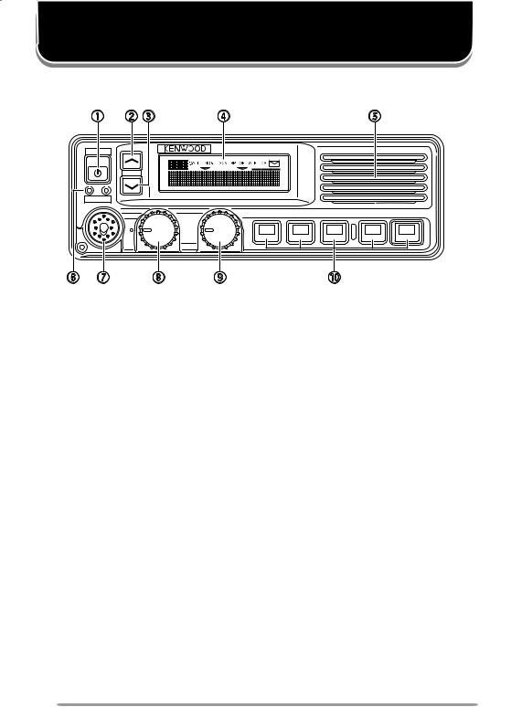
KCH-14 (Basic Control Panel) |
|
|
|
q |
w e |
r |
t |
POWER |
|
|
|
|
GRP |
|
|
TX BUSY |
|
|
|
|
VOL |
|
CH |
y u |
i |
o |
!0 |
qPower  switch
Press to switch the transceiver ON. Press and hold for approximately 1 second to switch the transceiver OFF.
wGRP  key
key
Press to increase the zone number. Also press to increase setting adjustments.
eGRP  key
key
Press to decrease the zone number. Also press to decrease setting adjustments.
rDisplay
Refer to page 5.
tSpeaker
Internal speaker.
yTX and BUSY indicators
The TX indicator lights red while transmitting. The BUSY indicator lights green while receiving.
uMicrophone jack
Insert the microphone plug into this jack.
iVOL (Volume) control
Rotate clockwise to increase the volume level. Rotate counterclockwise to decrease the volume level.
oCH (Channel) control
Rotate clockwise to increase the channel number. Rotate counterclockwise to decrease the channel number. Your dealer can also enable the CH control to be used when making setting adjustments, as an optional method for using the GRP  and GRP
  keys.
keys.
!0PF 1 ~ PF 5 (Programmable Function) keys
Press to activate their programmable functions {page 9}.
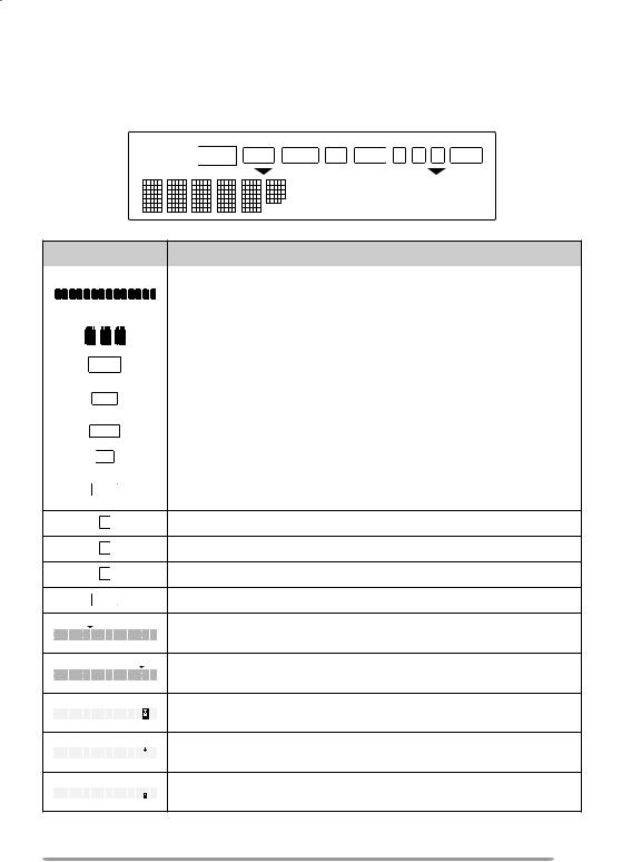
KCH-14 Display
Indicator |
Description |
||||||||||||||||||||||||
|
|
|
|
|
|
|
|
|
|
|
|
|
|
|
|
|
|
|
|
|
|
|
|
|
|
|
|
|
|
|
|
|
|
|
|
|
|
|
|
|
|
|
|
|
|
|
|
|
|
|
Displays the operating zone and channel numbers or zone |
|
|
|
|
|
|
|
|
|
|
|
|
|
|
|
|
|
|
|
|
|
|
|
|
|
and channel names. Also displays various text messages |
|
|
|
|
|
|
|
|
|
|
|
|
|
|
|
|
|
|
|
|
|
|
|
|
|
depending on the function being used. |
|
|
|
|
|
|
|
|
|
|
|
|
|
|
|
|
|
|
|
|
|
|
|
|
|
|
|
|
|
|
|
|
|
|
|
|
|
|
|
|
|
|
|
|
|
|
|
|
|
|
|
Displays various characters depending on dealer settings. |
|
|
|
|
|
|
|
|
|
|
|
|
|
|
|
|
|
|
|
|
|
|
|
|
|
|
|
|
|
|
|
|
|
|
|
|
|
|
|
|
|
|
|
|
|
|
|
|
|
|
|
Appears when a received call is using optional signaling. |
|
|
|
|
|
|
|
|
|
|
|
|
|
|
|
|
|
|
|
|
|
|
|
|
|
|
|
|
|
|
|
|
|
|
|
|
|
|
|
|
|
|
|
|
|
|
|
|
|
|
|
Appears when the Monitor function is active and when the |
|
|
|
|
|
|
|
|
|
|
|
|
|
|
|
|
|
|
|
|
|
|
|
|
|
transceiver squelch is open. |
|
|
|
|
|
|
|
|
|
|
|
|
|
|
|
|
|
|
|
|
|
|
|
|
|
Appears when you are using Scan mode. |
|
|
|
|
|
|
|
|
|
|
|
|
|
|
|
|
|
|
|
|
|
|
|
|
|
|
|
|
|
|
|
|
|
|
|
|
|
|
|
|
|
|
|
|
|
|
|
|
|
|
|
Appears when the external speaker function is activated. |
|
|
|
|
|
|
|
|
|
|
|
|
|
|
|
|
|
|
|
|
|
|
|
|
|
|
|
|
|
|
|
|
|
|
|
|
|
|
|
|
|
|
|
|
|
|
|
|
|
|
|
Appears when the Scrambler or Encryption function is |
|
|
|
|
|
|
|
|
|
|
|
|
|
|
|
|
|
|
|
|
|
|
|
|
|
activated. |
|
|
|
|
|
|
|
|
|
|
|
|
|
|
|
|
|
|
|
|
|
|
|
|
|
|
|
|
|
|
|
|
|
|
|
|
|
|
|
|
|
|
|
|
|
|
|
|
|
|
|
Appears when the AUX A function has been activated. |
|
|
|
|
|
|
|
|
|
|
|
|
|
|
|
|
|
|
|
|
|
|
|
|
|
|
|
|
|
|
|
|
|
|
|
|
|
|
|
|
|
|
|
|
|
|
|
|
|
|
|
Appears when the AUX B function has been activated. |
|
|
|
|
|
|
|
|
|
|
|
|
|
|
|
|
|
|
|
|
|
|
|
|
|
|
|
|
|
|
|
|
|
|
|
|
|
|
|
|
|
|
|
|
|
|
|
|
|
|
|
Appears when using the Operator Selectable Tone function. |
|
|
|
|
|
|
|
|
|
|
|
|
|
|
|
|
|
|
|
|
|
|
|
|
|
|
|
|
|
|
|
|
|
|
|
|
|
|
|
|
|
|
|
|
|
|
|
|
|
|
|
Appears when there is a message stored in the transceiver |
|
|
|
|
|
|
|
|
|
|
|
|
|
|
|
|
|
|
|
|
|
|
|
|
|
memory. Flashes when a new message has arrived. |
|
|
|
|
|
|
|
|
|
|
|
|
|
|
|
|
|
|
|
|
|
|
|
|
|
Appears when the selected zone is added to the scanning |
|
|
|
|
|
|
|
|
|
|
|
|
|
|
|
|
|
|
|
|
|
|
|
|
|
sequence. |
|
|
|
|
|
|
|
|
|
|
|
|
|
|
|
|
|
|
|
|
|
|
|
|
|
|
|
|
|
|
|
|
|
|
|
|
|
|
|
|
|
|
|
|
|
|
|
|
|
|
|
Appears when the selected channel is added to the scanning |
|
|
|
|
|
|
|
|
|
|
|
|
|
|
|
|
|
|
|
|
|
|
|
|
|
sequence. |
|
|
|
|
|
|
|
|
|
|
|
|
|
|
|
|
|
|
|
|
|
|
|
|
|
Appears when the AUX C function has been activated. |
|
|
|
|
|
|
|
|
|
|
|
|
|
|
|
|
|
|
|
|
|
|
|
|
|
|
|
|
|
|
|
|
|
|
|
|
|
|
|
|
|
|
|
|
|
|
|
|
|
|
|
|
|
|
|
|
|
|
|
|
|
|
|
|
|
|
|
|
|
|
|
|
|
|
|
|
|
Appears when the Auto Recording function on the VGS-1 |
|
|
|
|
|
|
|
|
|
|
|
|
|
|
|
|
|
|
|
|
|
|
|
|
|
|
|
|
|
|
|
|
|
|
|
|
|
|
|
|
|
|
|
|
|
|
|
|
|
|
|
option is activated. |
|
|
|
|
|
|
|
|
|
|
|
|
|
|
|
|
|
|
|
|
|
|
|
|
|
|
|
|
|
|
|
|
|
|
|
|
|
|
|
|
|
|
|
|
|
|
|
|
|
|
|
Appears when the Auto Reply Message on the VGS-1 option |
|
|
|
|
|
|
|
|
|
|
|
|
|
|
|
|
|
|
|
|
|
|
|
|
|
|
|
|
|
|
|
|
|
|
|
|
|
|
|
|
|
|
|
|
|
|
|
|
|
|
|
is activated. |
|
|
|
|
|
|
|
|
|
|
|
|
|
|
|
|
|
|
|
|
|
|
|
|
|
|

KCH-15 (Full-Featured Control Panel)
q w e |
r |
ty u |
POWER
|
MON |
SP |
A B C |
GRP |
|
SCN 
TX BUSY
VOL CH
i o |
!0 |
!1 |
!2 |
qPower  switch
Press to switch the transceiver ON. Press and hold for approximately 1 second to switch the transceiver OFF.
wGRP  key
key
Press to increase the zone number. Also press to increase setting adjustments.
eGRP  key
key
Press to decrease the zone number. Also press to decrease setting adjustments.
rDisplay
Refer to page 7.
tMON (Monitor) key
Press to activate the Monitor function. Press and hold to turn the transceiver Squelch OFF {page 32}.
ySCN (Scan) key
Press to activate the Scan function {page 15}.
uProgrammable Function keys
Press to activate their programmable functions {page 9}.
iTX and BUSY indicators
The TX indicator lights red while transmitting. The BUSY indicator lights green while receiving.
oMicrophone jack
Insert the microphone plug into this jack.
!0VOL (Volume) control
Rotate clockwise to increase the volume level. Rotate counterclockwise to decrease the volume level.
!1CH (Channel) control
Rotate clockwise to increase the channel number. Rotate counterclockwise to decrease the channel number. Your dealer can also enable the CH control to be used when making setting adjustments, as an optional method for using the GRP  and GRP
  keys.
keys.
!2PF 1 ~ PF 5 (Programmable Function) keys
Press to activate their programmable functions {page 9}.
KCH-15 Display
|
|
|
|
Indicator |
Description |
||
|
|
|
|
|
|
Displays the operating zone and channel numbers or zone |
|
|
|
and channel names. Also displays various text messages |
|
|
|
depending on the function being used. |
|
|
|
Displays various characters depending on dealer settings. |
|
|
|
|
|
|
|
Appears when a received call is using optional signaling. |
|
|
|
|
|
|
|
Appears when the Monitor function is active and when the |
|
|
|
transceiver squelch is open. |
|
|
|
|
|
|
|
Appears when you are using Scan mode. |
|
|
|
|
|
|
|
Appears when the external speaker function is activated. |
|
|
|
|
|
|
|
Appears when the Scrambler or Encryption function is |
|
|
|
activated. |
|
AAppears when the AUX A function has been activated.
BAppears when the AUX B function has been activated.
CAppears when the AUX C function has been activated.
Appears when using the Operator Selectable Tone function.
Appears when the selected zone is added to the scanning sequence.
Appears when the selected channel is added to the scanning sequence.
Appears when there is a message stored in the transceiver memory. Flashes when a new message has arrived.
Appears when the Auto Recording function on the VGS-1 option is activated.
Appears when the Auto Reply Message on the VGS-1 option is activated.
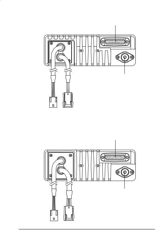
Mid Power Model Rear Panel
External accessory connector (D-sub 25 pin)
Antenna connector
External accessory |
Power input |
connector (9-pin) |
connector |
High Power Model Rear Panel
External accessory connector (D-sub 25 pin)
Antenna connector
External accessory |
Power input |
connector (9-pin) |
connector |
 Loading...