


 Loading...
NX-1000 series
USER MANUAL
B5A-3233-00_E_EN

CONTENTS |
|
MODELS COVERED BY THIS MANUAL......................................................... |
5 |
PREPARATION................................................................................................... |
6 |
INSTALLING THE ANTENNA......................................................................... |
6 |
INSTALLING/ REMOVING THE BATTERY PACK........................................... |
6 |
INSTALLING THE BELT CLIP......................................................................... |
7 |
INSTALLING THE CAP OVER THE SPEAKER/ MICROPHONE JACKS....... |
7 |
INSTALLING THE SPEAKER/ MICROPHONE OR HEADSET...................... |
8 |
ORIENTATION.................................................................................................... |
9 |
Buttons and Controls.................................................................................... |
9 |
Display........................................................................................................ |
10 |
BASIC OPERATIONS....................................................................................... |
11 |
SWITCHING POWER ON/ OFF................................................................... |
11 |
ADJUSTING THE VOLUME.......................................................................... |
11 |
SELECTING A ZONE AND CHANNEL......................................................... |
11 |
TRANSMITTING........................................................................................... |
12 |
Making Group Calls (NXDN/ DMR)............................................................. |
12 |
Making Individual Calls (NXDN/ DMR)....................................................... |
13 |
RECEIVING.................................................................................................. |
13 |
Receiving Group Calls (NXDN/ DMR)........................................................ |
14 |
Receiving Individual Calls (NXDN/ DMR)................................................... |
14 |
ACCESSIBLE FUNCTIONS............................................................................. |
15 |
FUNCTION MODE.......................................................................................... |
15 |
MENU MODE (LCD Model).......................................................................... |
15 |
Menu Access.............................................................................................. |
15 |
FUNCTIONS LIST........................................................................................... |
17 |
FUNCTIONS OVERVIEW .............................................................................. |
22 |
FUNCTION DESCRIPTIONS............................................................................ |
63 |
TRANSCEIVER PASSWORD......................................................................... |
63 |
LCD Model.................................................................................................... |
63 |
Non LCD Model............................................................................................ |
64 |
SCAN.............................................................................................................. |
65 |
2

TEMPORARY CHANNEL LOCKOUT........................................................... |
65 |
PRIORITY SCAN.......................................................................................... |
65 |
SCAN REVERT............................................................................................. |
66 |
EMERGENCY CALLS..................................................................................... |
67 |
SCRAMBLER (ANALOG)/ ENCRYPTION (NXDN/ DMR).............................. |
68 |
SECURE (ENCRYPTED) TRANSMISSION................................................. |
68 |
SELECTING THE SCRAMBLER CODE....................................................... |
68 |
SELECTING THE ENCRYPTION KEY......................................................... |
69 |
SIGNALING..................................................................................................... |
70 |
QUIET TALK (QT)/ DIGITAL QUIET TALK (DQT) [ANALOG]....................... |
70 |
Operator Selectable Tone (OST) [Analog]................................................... |
70 |
RADIO ACCESS NUMBER (RAN) [NXDN].................................................. |
70 |
COLOR CODE (CC) [DMR].......................................................................... |
70 |
OPTIONAL SIGNALING............................................................................... |
71 |
5-tone Signaling [Analog]............................................................................ |
71 |
DTMF Signaling [Analog]............................................................................ |
71 |
MDC-1200 Signaling [Analog]..................................................................... |
71 |
FleetSync Signaling [Analog]...................................................................... |
71 |
NXDN ID Signaling [NXDN]........................................................................ |
71 |
FleetSync: ALPHANUMERIC 2-WAY PAGING FUNCTION............................ |
72 |
SELCALL (SELECTIVE CALLING)............................................................... |
72 |
Transmitting................................................................................................. |
72 |
Receiving.................................................................................................... |
72 |
Identification Codes.................................................................................... |
73 |
STATUS MESSAGE...................................................................................... |
73 |
Transmitting................................................................................................. |
73 |
Receiving.................................................................................................... |
73 |
SHORT MESSAGES..................................................................................... |
74 |
GPS REPORT............................................................................................... |
74 |
5-TONE SIGNALING...................................................................................... |
75 |
SELCALL (SELECTIVE CALLING)............................................................... |
75 |
Transmitting................................................................................................. |
75 |
Receiving.................................................................................................... |
75 |
3

STATUS MESSAGE...................................................................................... |
76 |
Transmitting................................................................................................. |
76 |
Receiving.................................................................................................... |
76 |
VOICE OPERATED TRANSMISSION (VOX).................................................. |
77 |
VOX Type.................................................................................................... |
77 |
VOX Operation............................................................................................ |
77 |
Semi-VOX Operation................................................................................... |
77 |
VOX Gain Level........................................................................................... |
78 |
BACKGROUND OPERATIONS...................................................................... |
79 |
TIME-OUT TIMER (TOT).............................................................................. |
79 |
BATTERY SAVER......................................................................................... |
79 |
LOW BATTERY WARNING........................................................................... |
79 |
SIGNAL STRENGTH INDICATOR................................................................ |
79 |
VOICE ANNOUNCEMENT........................................................................... |
80 |
BUSY CHANNEL LOCKOUT (BCL).............................................................. |
81 |
4

MODELS COVERED BY THIS MANUAL
The models listed below are covered by this manual:
NXDN/ Analog Transceiver
NX-1200N (VHF TRANSCEIVER)
NX-1300N (UHF TRANSCEIVER)
DMR/ Analog Transceiver
NX-1200D (VHF TRANSCEIVER)
NX-1300D (UHF TRANSCEIVER)
5
PREPARATION
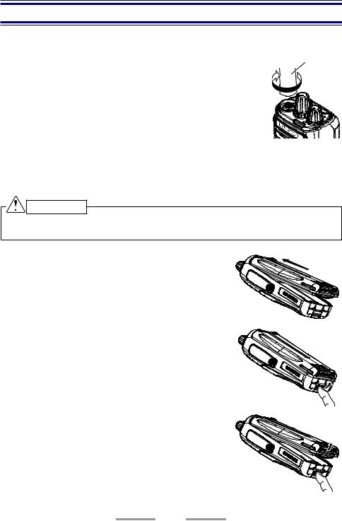
INSTALLING THE ANTENNA
Screw the antenna into the connector on the top of the |
Antenna |
transceiver by holding the antenna at its base and turning it |
|
clockwise until secure. |
|
INSTALLING/ REMOVING THE BATTERY PACK
The battery pack is not charged at the factory; charge it before use.
CAUTION
Do not short the battery terminals or dispose of the battery by fire.Never attempt to remove the casing from the battery pack.
1 Align the battery pack with the back of the transceiver, then press the battery pack and transceiver firmly together until the release latch on the base of the transceiver locks.
2 To remove the battery pack, lift the safety catch on the base of the transceiver, then press the release latch underneath the safety catch.
3 While pressing the release latch, pull the battery pack away from the transceiver.
6
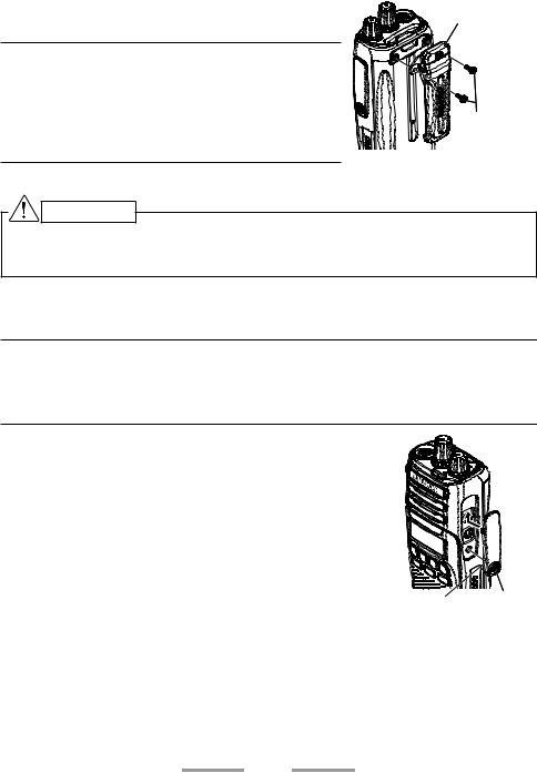
INSTALLING THE BELT CLIP
If necessary, attach the belt clip using the two supplied M3 x 8 mm binding screws.
Note:
If the belt clip is not installed, its mounting location may get hot during continuous transmission or when left sitting in a hot environment.
Use the Phillips #2 screwdriver.
Belt clip
M3 x 8 mm screws
CAUTION
Do not use glue which is designed to prevent screw loosening when installing the belt clip, as it may cause damage to the transceiver. Acrylic ester, which is contained in these glues, may crack the transceiver’s back panel.
INSTALLING THE CAP OVER THE SPEAKER/ MICROPHONE JACKS
Note:
To keep the transceiver water resistant, you must cover the speaker/ microphone jacks with the supplied cap.
Use the Phillips #1 screwdriver.
1 If you are not using an optional speaker/ microphone or headset, install the cap over the speaker/ microphone jacks.
2 Secure the cap in place using the attached screw.
Speaker/ microphone |
Screw |
|
|
jack cap |
|
7

INSTALLING THE SPEAKER/ MICROPHONE OR HEADSET
Note:
The transceiver is not fully water resistant when using a speaker/ microphone or headset.
Use the Phillips #1 screwdriver.
1 Insert the speaker/ microphone plugs into the speaker/ microphone jacks of the transceiver.
2 Place the locking bracket over the speaker/ microphone plugs so that the locking tabs insert into the transceiver grooves.
3 Secure the locking bracket in place using the attached screw.
Speaker/ microphone |
Screw |
|
|
locking bracket |
|
8
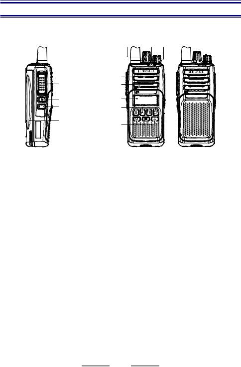
ORIENTATION
Buttons and Controls
A B C
 Antenna
|
|
Speaker |
F |
Microphone |
|
G |
|
Display |
|
|
|
H |
|
D |
Battery pack |
E |
|
|
|
|
ASelector
Rotate to change the operating channel.
BStatus indicator
Lights during a specified mode, based on dealer programming. (Red, Purple, Blue, Light Blue, Green, Yellow, White)
CPower switch/ Volume control
Turn clockwise to switch ON the transceiver. To switch OFF the transceiver, turn counterclockwise until a click sounds. Rotate to adjust the volume level.
D[ S ], [ A ], [ <B ], and [ C> ] buttons
•Used for each setting operation.
•Press to activate its programmable function.
E[ ], [ ], and [ ] buttons
Press to activate its programmable function.
FPTT (Push to Talk) switch
Press and hold, then speak into the microphone to transmit.
GSide 1 button
Press to activate its programmable function.
HSide 2 button
Press to activate its programmable function.
9

Display
Indicator |
|
|
|
|
|
|
|
|
|
|
|
|
|
|
|
|
|
|
|
|
|
|
|
|
|
|
|
|
|
|
|
|
|
|
Description |
|||
|
|
|
|
|
|
|
|
|
||||
Displays the signal strength.
The Monitor or Squelch Off function is activated.
Blinks when an incoming call matches your Optional Signaling.
The Talk Around function is activated.
Scan, Priority Scan, or Voting/ Site Roaming is in progress. Blinks when the scan is paused.
A message is stored in the memory. Blinks when a new message is received.
Indicates Priority Channel.
The channel is using low transmit power.
The Scrambler/ Encryption function is activated. Blinks when receiving an encrypted carrier.
Displays the battery power.
Left side: The current zone is added to the Multi-Zone scanning sequence.
Right side: The current channel is added to the scanning sequence.
The VOX function is activated.
10
BASIC OPERATIONS
SWITCHING POWER ON/ OFF
Turn the Power switch/ Volume control clockwise to switch the transceiver power ON.
•The Power on text appears if the Power on text has been set.
Turn the Power switch/ Volume control counterclockwise to switch the transceiver power OFF.
ADJUSTING THE VOLUME
Rotate the Power switch/ Volume control to adjust the volume.
Rotate clockwise to increase the volume and counterclockwise to decrease the volume.
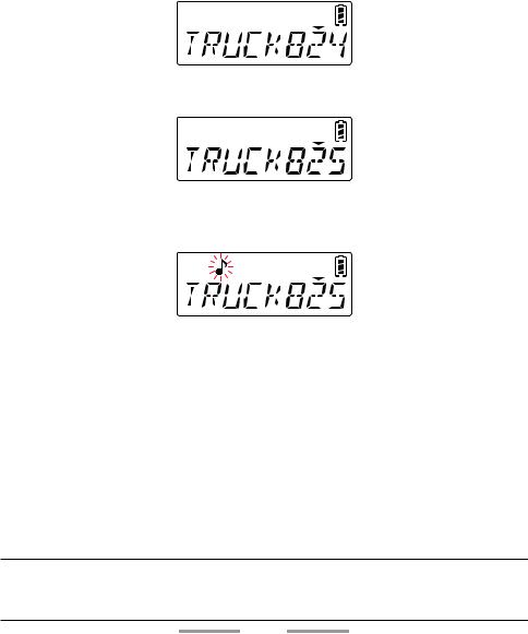
SELECTING A ZONE AND CHANNEL
1Select the desired zone using the buttons programmed as [Zone Up]/ [Zone Down].
•Each zone contains a group of channels.
2Select the desired channel using the Selector or buttons programmed as
[Channel Up]/ [Channel Down].
•Each channel is programmed with settings for transmitting and receiving.
•The transceiver may have names programmed for zones and channels. The zone name and channel name can contain up to 8 characters respectively. While selecting a zone, the zone name appears for 2 seconds (if Zone Name Display is set), then channel name appears.
11

TRANSMITTING
1Select the desired zone and channel.
2Press the button programmed as [Monitor] or [Squelch Off] to check whether or not the channel is free.
•If the channel is busy, wait until it becomes free.
3Press the PTT switch and speak to the microphone. Release the PTT switch to receive.
•The LED indicator lights red while transmitting and green while receiving a signal. This indicator can also be disabled by your dealer.
•For best sound quality, hold the transceiver approximately 3 ~ 4 cm (1.5 inches) from your mouth.
•In Site Roaming, In Voting and Voting with Signaling zones, the transceiver will search for the strongest signal repeater and transmit using that repeater’s frequency.
Making Group Calls (NXDN/ DMR)
You can select a group ID from the list to make a call to those parties on a channel.
1Press the button programmed as [Group], [Group + Short Message] or [Group + Status] to enter Group Call Mode.
•Alternatively, press the button programmed as [Menu] to enter Group Call Mode using the Menu Mode.
•The group ID list appears on the display.
2Press the [ <B ] and [ C> ] buttons to select a Group ID/ name from the list that has been programmed into your transceiver.
3Press and hold the PTT switch to make the call.
•The “  ” indicator blinks. The Group name of the target transceiver are displayed.
•Speak to the microphone as you would during a normal call.
12
Making Individual Calls (NXDN/ DMR)
You can select a Unit ID/ name from the list to make a call to those parties on a channel.
1Press the button programmed as [Individual], [Individual + Short Message] or [Individual + Status] to enter Individual Call Mode.
•Alternatively, press the button programmed as [Menu] to enter Individual Call Mode using the Menu Mode.
•The ID list appears on the display.
2Press the [ <B ] and [ C> ] buttons to select a Unit ID/ name from the list that has been programmed into your transceiver.
3Press and hold the PTT switch to make the call.
•The “  ” indicator blinks. The ID name of the target transceiver are displayed.
•Speak to the microphone as you would during a normal call.
RECEIVING
1Select the desired zone and channel. (If the Scan function has been programmed, you can switch it On or Off as desired.)
2When you hear the caller’s voice, readjust the volume as necessary.
•If signaling has been programmed on the selected channel, you will hear a call only if the signaling matches the signaling set up on your transceiver. Refer to “OPTIONAL SIGNALING” {p. 71} for details.
•In Site Roaming, In Voting and Voting with Signaling zones, the transceiver will automatically search for the strongest signal and receive on that frequency.
Note:
A ringing tone will sound when receiving a call if the alert tone has been enabled in the AlertTone setting.For details, consult your dealer.
13

Receiving Group Calls (NXDN/ DMR)
When you receive a group call on a channel and the received group ID matches the ID set up on your transceiver, you can hear the caller’s voice.
Receiving Individual Calls (NXDN/ DMR)
When you receive an individual call on a channel, a ringing tone will sound and the display will show the caller’s ID.
Note:
When water gets into the microphone opening or the speaker grill, the voice level of the transmission and reception may become low or distorted.Lightly shake the transceiver to remove the water from the speaker and/or microphone before operating the transceiver.
14

ACCESSIBLE FUNCTIONS
FUNCTION MODE
Your transceiver operations vary according to the functions that your dealer has programmed to the transceiver buttons. Refer to “FUNCTIONS LIST” {p. 17} for the available programmable functions.
MENU MODE (LCD Model)
Many functions on this transceiver are selected or configured through the Menu instead of physical controls. Once you become familiar with the Menu system, you will appreciate the versatility it offers.
Some transceiver buttons may already be programmed with functions listed in the Menu. Those functions can be accessed directly by pressing the button. All other functions can still be accessed using the transceiver Menu. Refer to “FUNCTIONS LIST” for the available Menu items.
•Menu Mode can register functions by category (Up to 12 categories). Example:
Category |
Function |
|
|
CALL |
Individual, Group, Status, Stack |
|
|
SCAN |
Scan, Scan Delete/Add |
|
|
AUD/TONE |
Squelch Off, Squelch Level |
|
|
•The category does not appear in Menu Mode when only one category is configured. When the transceiver enters Menu Mode, the functions registered in Menu Mode appear.
Menu Access
1Press the button programmed as [Menu].
•The category list is shown.
•When there is only one category, the function list is shown (proceed to step 4).
2Press [ <B ] and [ C> ] buttons to select a category item.
15

3Press the [ S ] button to view the function list for the selected category.
4Press [ <B ] and [ C> ] to select a function item.
•Press the [ A ] button to return to the category list.
5Press the [ S ] button. The selected function functions.
•Options for a function, such as Microphone type, can be selected by pressing the [ <B ] and [ C> ] buttons and then can be confirmed by pressing the [ S ] button.
•Press the Side 1 button at any time to exit Menu Mode.
16

FUNCTIONS LIST
PF Button : Functions that can be programmed to the transceiver buttons Menu : Functions that can be accessed using the transceiver Menu Non-LCD : Non-LCD Model
Analog : Channels set up for Analog NXDN : Channels set up for NXDN DMR : Channels set up for DMR
: Available
N/A: Not Available
Function |
Menu |
PF |
Menu |
Non- |
Analog |
NXDN |
DMR |
|
Display |
Button |
LCD |
||||||
|
|
|
|
|
||||
|
|
|
|
|
|
|
|
|
None |
– |
|
N/A |
|
|
|
|
|
|
|
|
|
|
|
|
|
|
Autodial |
AUTODIAL |
|
|
N/A |
|
N/A |
N/A |
|
|
|
|
|
|
|
|
|
|
Backlight |
– |
|
N/A |
N/A |
|
|
|
|
|
|
|
|
|
|
|
|
|
Battery Status |
BAT STAT |
|
|
|
|
|
|
|
|
|
|
|
|
|
|
|
|
Broadcast |
BCST |
|
|
|
N/A |
N/A |
|
|
|
|
|
|
|
|
|
|
|
Button Lock |
– |
|
N/A |
|
|
|
|
|
|
|
|
|
|
|
|
|
|
Call 1 ~ 6 |
– |
|
N/A |
|
|
|
|
|
|
|
|
|
|
|
|
|
|
Calling Alert |
– |
|
N/A |
|
|
N/A |
N/A |
|
|
|
|
|
|
|
|
|
|
Call Interruption |
– |
|
N/A |
|
N/A |
N/A |
|
|
|
|
|
|
|
|
|
|
|
Call Response |
– |
|
N/A |
|
N/A |
|
|
|
|
|
|
|
|
|
|
|
|
Channel Down |
– |
|
N/A |
N/A |
|
|
|
|
|
|
|
|
|
|
|
|
|
Channel Down |
– |
|
N/A |
N/A |
|
|
|
|
(Continuous) |
||||||||
|
|
|
|
|
|
|
||
|
|
|
|
|
|
|
|
|
Channel Entry |
– |
|
N/A |
N/A |
|
|
|
|
|
|
|
|
|
|
|
|
|
Channel Recall |
– |
|
N/A |
|
|
|
|
|
|
|
|
|
|
|
|
|
|
Channel Up |
– |
|
N/A |
N/A |
|
|
|
|
|
|
|
|
|
|
|
|
|
Channel Up |
– |
|
N/A |
N/A |
|
|
|
|
(Continuous) |
||||||||
|
|
|
|
|
|
|
||
|
|
|
|
|
|
|
|
|
Clear |
– |
|
N/A |
|
|
|
|
|
|
|
|
|
|
|
|
|
|
CW Message |
– |
|
N/A |
|
N/A |
|
N/A |
|
|
|
|
|
|
|
|
|
|
Digit 1x Down |
– |
|
N/A |
N/A |
|
N/A |
N/A |
|
|
|
|
|
|
|
|
|
|
Digit 1x Up |
– |
|
N/A |
N/A |
|
N/A |
N/A |
|
|
|
|
|
|
|
|
|
17

Function |
Menu |
PF |
Menu |
Non- |
Analog |
NXDN |
DMR |
|
Display |
Button |
LCD |
||||||
|
|
|
|
|
||||
|
|
|
|
|
|
|
|
|
Digit 10x Down |
– |
|
N/A |
N/A |
|
N/A |
N/A |
|
|
|
|
|
|
|
|
|
|
Digit 10x Up |
– |
|
N/A |
N/A |
|
N/A |
N/A |
|
|
|
|
|
|
|
|
|
|
Direct Channel |
– |
|
N/A |
|
|
|
|
|
1 ~ 5 |
||||||||
|
|
|
|
|
|
|
||
|
|
|
|
|
|
|
|
|
Direct Channel 1 |
DR 1 SEL |
|
|
|
|
|
|
|
~ DR 5 |
|
|
|
|
|
|
||
~ 5 Select |
||||||||
SEL |
|
|
|
|
|
|
||
|
|
|
|
|
|
|
||
|
|
|
|
|
|
|
|
|
Display Format |
DISP FMT |
|
|
N/A |
|
|
|
|
|
|
|
|
|
|
|
|
|
Emergency |
– |
|
N/A |
|
|
|
|
|
|
|
|
|
|
|
|
|
|
External |
|
|
|
|
|
|
|
|
Microphone |
EX MIC S |
N/A |
|
N/A |
|
|
|
|
Sense |
|
|
|
|
|
|
|
|
|
|
|
|
|
|
|
|
|
External Speaker |
SPEAKER |
|
|
|
|
|
|
|
|
|
|
|
|
|
|
|
|
Fixed Volume |
FIXED V |
|
|
|
|
|
|
|
|
|
|
|
|
|
|
|
|
Function |
– |
|
N/A |
|
|
|
|
|
|
|
|
|
|
|
|
|
|
Group |
GRP |
|
|
N/A |
|
|
|
|
MODE |
||||||||
|
|
|
|
|
|
|
||
|
|
|
|
|
|
|
|
|
Group + Short |
GRP SDM |
|
|
N/A |
|
|
|
|
Message |
||||||||
|
|
|
|
|
|
|
||
|
|
|
|
|
|
|
|
|
Group + Status |
GRP STAT |
|
|
N/A |
|
|
|
|
|
|
|
|
|
|
|
|
|
High Transmit |
HIGH |
|
|
|
|
|
|
|
Power |
PWR |
|||||||
|
|
|
|
|
|
|||
|
|
|
|
|
|
|
|
|
Home Channel |
– |
|
N/A |
|
|
|
|
|
|
|
|
|
|
|
|
|
|
Home Channel |
HOME |
|
|
|
|
|
|
|
Select |
SEL |
|||||||
|
|
|
|
|
|
|||
|
|
|
|
|
|
|
|
|
Individual |
IND |
|
|
N/A |
|
|
|
|
MODE |
||||||||
|
|
|
|
|
|
|
||
|
|
|
|
|
|
|
|
|
Individual + |
IND SDM |
|
|
N/A |
|
|
|
|
Short Message |
||||||||
|
|
|
|
|
|
|
||
|
|
|
|
|
|
|
|
|
Individual + |
IND STAT |
|
|
N/A |
|
|
|
|
Status |
||||||||
|
|
|
|
|
|
|
||
|
|
|
|
|
|
|
|
|
Lone Worker |
L-WK |
|
|
|
|
|
|
|
|
|
|
|
|
|
|
|
|
Low Transmit |
LOW PWR |
|
|
|
|
|
|
|
Power |
||||||||
|
|
|
|
|
|
|
||
|
|
|
|
|
|
|
|
18

Function |
Menu |
PF |
Menu |
Non- |
Analog |
NXDN |
DMR |
|
Display |
Button |
LCD |
||||||
|
|
|
|
|
||||
|
|
|
|
|
|
|
|
|
Maintenance |
MAINT |
|
|
N/A |
|
|
|
|
|
|
|
|
|
|
|
|
|
Manual Site Hunt |
M SITE H |
|
|
|
N/A |
N/A |
|
|
|
|
|
|
|
|
|
|
|
Medium 1 |
MED 1 P |
N/A |
|
N/A |
|
|
|
|
Transmit Power |
||||||||
|
|
|
|
|
|
|
||
|
|
|
|
|
|
|
|
|
Medium 2 |
MED 2 P |
N/A |
|
N/A |
|
|
|
|
Transmit Power |
||||||||
|
|
|
|
|
|
|
||
|
|
|
|
|
|
|
|
|
Menu |
– |
|
N/A |
N/A |
|
|
|
|
|
|
|
|
|
|
|
|
|
Microphone |
MIC SENS |
N/A |
|
N/A |
|
|
|
|
Sense |
||||||||
|
|
|
|
|
|
|
||
|
|
|
|
|
|
|
|
|
Microphone Type |
MIC TYPE |
N/A |
|
N/A |
N/A |
|
|
|
|
|
|
|
|
|
|
|
|
Monitor |
MONITOR |
|
|
|
|
|
|
|
|
|
|
|
|
|
|
|
|
Monitor |
– |
|
N/A |
|
|
|
|
|
Momentary |
||||||||
|
|
|
|
|
|
|
||
|
|
|
|
|
|
|
|
|
Operator |
OST |
|
|
N/A |
|
N/A |
N/A |
|
Selectable Tone |
||||||||
|
|
|
|
|
|
|
||
OST List |
OST LIST |
|
|
N/A |
|
N/A |
N/A |
|
|
|
|
|
|
|
|
|
|
OVCM |
OVCM |
|
|
|
N/A |
N/A |
|
|
|
|
|
|
|
|
|
|
|
Priority-channel |
PRIORITY |
|
|
N/A |
|
|
|
|
Select |
||||||||
|
|
|
|
|
|
|
||
|
|
|
|
|
|
|
|
|
Radio Check |
RD CHK |
N/A |
|
N/A |
|
N/A |
N/A |
|
(MDC-1200) |
||||||||
|
|
|
|
|
|
|
||
|
|
|
|
|
|
|
|
|
Radio Inhibit |
INHIBIT |
N/A |
|
N/A |
|
N/A |
N/A |
|
(MDC-1200) |
||||||||
|
|
|
|
|
|
|
||
|
|
|
|
|
|
|
|
|
Radio Uninhibit |
UNINHIB |
N/A |
|
N/A |
|
N/A |
N/A |
|
(MDC-1200) |
||||||||
|
|
|
|
|
|
|
||
|
|
|
|
|
|
|
|
|
Remote Control |
RMT |
|
|
N/A |
N/A |
|
|
|
CTRL |
||||||||
|
|
|
|
|
|
|
||
|
|
|
|
|
|
|
|
|
RX Audio |
RX EQ |
N/A |
|
N/A |
N/A |
|
|
|
Equalizer |
||||||||
|
|
|
|
|
|
|
||
|
|
|
|
|
|
|
|
|
RX Auto Gain |
RX AGC |
N/A |
|
N/A |
N/A |
|
|
|
Control |
||||||||
|
|
|
|
|
|
|
||
|
|
|
|
|
|
|
|
|
Save Log Data |
SAVE |
|
|
|
|
|
|
|
LOG |
||||||||
|
|
|
|
|
|
|
||
|
|
|
|
|
|
|
|
|
Scan |
SCAN |
|
|
|
|
|
|
|
|
|
|
|
|
|
|
|
19

Function |
Menu |
PF |
Menu |
Non- |
Analog |
NXDN |
DMR |
|
Display |
Button |
LCD |
||||||
|
|
|
|
|
||||
|
|
|
|
|
|
|
|
|
Scan Delete/ |
SCN D/A |
|
|
|
|
|
|
|
Add |
||||||||
|
|
|
|
|
|
|
||
|
|
|
|
|
|
|
|
|
Scrambler/ |
SCRENC |
|
|
|
|
|
|
|
Encryption |
||||||||
|
|
|
|
|
|
|
||
|
|
|
|
|
|
|
|
|
Scrambler/ |
SCRENC |
|
|
N/A |
|
|
|
|
Encryption Code |
C |
|||||||
|
|
|
|
|
|
|||
|
|
|
|
|
|
|
|
|
Send the GPS |
SEND |
|
|
|
|
|
|
|
Data |
GPS |
|||||||
|
|
|
|
|
|
|||
|
|
|
|
|
|
|
|
|
Short Message |
SDM |
|
|
N/A |
|
|
|
|
MODE |
||||||||
|
|
|
|
|
|
|
||
|
|
|
|
|
|
|
|
|
Speaker |
– |
|
N/A |
|
|
|
|
|
Attenuation |
||||||||
|
|
|
|
|
|
|
||
Speaker Type |
SPK TYPE |
N/A |
|
N/A |
N/A |
|
|
|
|
|
|
|
|
|
|
|
|
Squelch Level |
SQL LVL |
|
|
N/A |
|
N/A |
N/A |
|
|
|
|
|
|
|
|
|
|
Squelch Off |
SQL OFF |
|
|
|
|
|
|
|
|
|
|
|
|
|
|
|
|
Squelch Off |
– |
|
N/A |
|
|
|
|
|
Momentary |
||||||||
|
|
|
|
|
|
|
||
|
|
|
|
|
|
|
|
|
Stack |
STACK |
|
|
N/A |
|
|
|
|
|
|
|
|
|
|
|
|
|
Status |
STATUS |
|
|
N/A |
|
|
|
|
|
|
|
|
|
|
|
|
|
Surveillance |
SURVEIL |
|
|
N/A |
|
|
|
|
|
|
|
|
|
|
|
|
|
Talk Around |
TALK ARD |
|
|
|
|
|
|
|
|
|
|
|
|
|
|
|
|
Transceiver |
TRNS |
|
|
N/A |
|
|
|
|
Password |
PWD |
|||||||
|
|
|
|
|
|
|||
|
|
|
|
|
|
|
|
|
TX Audio |
TX EQ |
N/A |
|
N/A |
N/A |
|
|
|
Equalizer |
||||||||
|
|
|
|
|
|
|
||
|
|
|
|
|
|
|
|
|
TX Auto Gain |
TX AGC |
N/A |
|
N/A |
N/A |
|
|
|
Control |
||||||||
|
|
|
|
|
|
|
||
|
|
|
|
|
|
|
|
|
VOX |
VOX LVL |
|
|
|
|
|
|
|
|
|
|
|
|
|
|
|
|
VOX Function |
VOX |
|
|
|
|
|
|
|
|
|
|
|
|
|
|
|
|
Zone Delete/ |
ZONE D/A |
|
|
|
|
|
|
|
Add |
||||||||
|
|
|
|
|
|
|
||
|
|
|
|
|
|
|
|
|
Zone Down |
– |
|
N/A |
|
|
|
|
|
|
|
|
|
|
|
|
|
|
Zone Down |
– |
|
N/A |
|
|
|
|
|
(Continuous) |
||||||||
|
|
|
|
|
|
|
||
|
|
|
|
|
|
|
|
20
Function |
Menu |
PF |
Menu |
Non- |
Analog |
NXDN |
DMR |
|
Display |
Button |
LCD |
||||||
|
|
|
|
|
||||
|
|
|
|
|
|
|
|
|
Zone Up |
– |
|
N/A |
|
|
|
|
|
|
|
|
|
|
|
|
|
|
Zone Up |
– |
|
N/A |
|
|
|
|
|
(Continuous) |
||||||||
|
|
|
|
|
|
|
||
|
|
|
|
|
|
|
|
21

FUNCTIONS OVERVIEW
Following is a brief overview of the functions available on the transceiver accessible using the Menu and/or programmable to the transceiver buttons.
•For details on functions that are not included in “FUNCTIONS OVERVIEW” and “FUNCTION DESCRIPTIONS” {p. 63}, please consult your dealer.
None [Analog/ NXDN/ DMR]
No function has been programmed.
Autodial [Analog]
Allows you to quickly send DTMF codes from the Autodial List.
1PF Button: Press the programmed button to enter Autodial Mode.
Menu Mode: Select “AUTODIAL” and press the [ S ] button to enter Autodial Mode.
2Press the [ <B ] and [ C> ] buttons to select your desired list of Autodial.
3Press the PTT switch to make the call.
Backlight [Analog/ NXDN/ DMR]
Allows you can turn the LCD display backlight on/off.
PF Button:
Press the programmed button to turn the display backlight On or Off.
•If Auto backlight is activated by your dealer, the backlight can be set to activate by button operations or when receiving a call/ message.
22

Battery Status [Analog/ NXDN/ DMR]
Allows you to check the battery power status.
PF Button:
Press the programmed button, the Battery Status function operates.
Menu Mode:
Select “BAT STAT” and press the [ S ] button, the Battery Status function operates.
Battery status is represented by the number of times the LED indicator flashes red. Four flashes represents full power, three represents medium power, two represents low power, and one represents very low power. If the LED flashes red only one time, recharge or replace your battery pack immediately.
Battery remaining |
LED |
Beep tone |
Indicator |
||||||
(LCD-Model) |
|||||||||
|
|
|
|||||||
|
|
|
|
|
|
|
|
|
|
Full |
Blink 4 times |
Sounds 4 times |
|
|
|
|
|
|
|
|
|
|
|
|
|
|
|
|
|
Sufficient |
Blink 3 times |
Sounds 3 times |
|
|
|
|
|
|
|
|
|
|
|
|
|
|
|
|
|
Low |
Blink 2 times |
Sounds 2 times |
|
|
|
|
|
|
|
|
|
|
|
|
|
|
|
|
|
Very Low |
Blink 1 time |
Sounds 1 time |
|
|
|
|
|
|
|
|
|
|
|
|
|
||||
|
|
|
|
|
|
||||
|
|
|
|
|
|
||||
|
|
|
|
|
|
|
|
|
|
|
|
|
|
|
|
|
|
|
|
|
|
|
|
|
|
|
|
|
|
•When the Low Battery Warning function is active {p. 79} and the battery power is low or less, this button will not operate.
•If the Battery Level Tone has been enabled, a beep tone will sound according to the number of flashes from the LED.
Broadcast [DMR]
Allows you to make a Broadcast Group Call. Broadcast Group Call can be used to engage in one-way informative group voice calls by initiating a call to a group.
PF Button:
Press the programmed button, to switch to Broadcast Call.
Menu Mode:
Select “BCST” and press the [ S ] button to switch to Broadcast Call.
•“BCST ON” is displayed for 1 second and Broadcast Group Call will be On.
23

Button Lock [Analog/ NXDN/ DMR]
Locking the transceiver button operation. This function prevents the incorrect operation of the transceiver by physical contact while carrying the transceiver, such as around the waist.
PF Button:
Press the programmed button to lock the transceiver buttons.
•Beep A (1 beep) sounds. Press the button again to unlock.
•Beep B (2 beeps) sounds.
•While Button Lock is on, operate a button that has been locked. “LOCKED” is displayed for 1 second.
•Even if a button on the transceiver is pressed while the Button Lock is enabled, a Button-entry Error Tone (1 beep) sounds.
•Whether each button operation is targeted for the Button Lock can be configured by your dealer. The following buttons are targeted for the Button Lock when each configuration is enabled:
-- Selector, Front Buttons, Side Buttons, Volume Control, and PTT Switch.
•The following will still function and can be operated as per normal.
-- Backlight, Battery Status, Button Lock, Call Response, Clear, Emergency, Function, Monitor, Monitor Momentary, Lone Worker, Squelch Off, and Squelch Off Momentary.
Call 1 ~ 6 [Analog/ NXDN/ DMR]
Allows you to send assigned signaling from Call 1 to Call 6.
PF Button:
Press the programmed button to send a message or initiate a call.
Calling Alert [Analog]
Allows you to send a calling alert to the other party. Calling alert tones help identify yourself to party members and inform them that you are calling.
PF Button:
Press the programmed button to send an Alert tone to a receiver.
24

Call Interruption [DMR]
Allows a transceiver other than the transmitting transceiver to terminate voice communications by sending a Call Interruption request message. If a transceiver receives a Call Interruption request message on the channel where the transceiver is performing voice communications, the transceiver terminates the voice communications.
PF Button:
Press the programmed button to send Call Interruption Request message.
Call Response [NXDN/ DMR]
Allows you to send an acknowledge call, upon receipt of the acknowledgment request message from an individual call.
PF Button:
Press the programmed button to respond to an Individual Call.
Channel Up/ Channel Down [Analog/ NXDN/ DMR]
PF Button:
Press the programmed button to increase/ decrease the channel number.
Channel Up (Continuous)/ Channel Down (Continuous)
[Analog/ NXDN/ DMR]
PF Button:
Hold down the programmed button to continuously increase/ decrease the channel number.
25
Loading...