


COMPACT HI-FI SYSTEM
NV-SERIES
NV-701/NV-301
INSTRUCTION MANUAL
KENWOOD CORPORATION
This instruction manual is used to describe multiple models listed above. Model availability and features (functions) may differ depending on the country and sales area.
B60-4755-00 (EN)
2 |
Before applying power |
Caution : Read this page carefully to ensure safe operation. |
|
|
|
|
|
|
|
|
|
|
|
|
|
Units are designed for operation as follows.
U.S.A. and Canada ............................................ |
AC 120 V only |
Australia ............................................................. |
AC 240 V only |
Europe and U.K. ................................................. |
AC 230 V only |
China.................................................................... |
AC 220 V only |
*Other countries ........... |
AC 110-120 / 220-240 V switchable |
Preparation section
For the United Kingdom
Factory fitted moulded mains plug
1.The mains plug contains a fuse. For replacement, use only a 13-Amp ASTA-approved (BS1362) fuse.
2.The fuse cover must be refitted when replacing the fuse in the moulded plug.
3.Do not cut off the mains plug from this equipment. If the plug fitted is not suitable for the power points in your home or the cable is too short to reach a power point, then obtain an appropriate safety approved extension lead or adapter, or consult your dealer.
If nonetheless the mains plug is cut off, remove the fuse and dispose of the plug immediately, to avoid a possible shock hazard by inadvertent connection to the mains supply.
IMPORTANT: The wires in the mains lead are colored in accordance with the following code: Blue : Neutral
Brown : Live
Do not connect those leads to the earth terminal of a threepin plug.
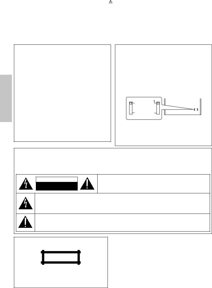
*AC voltage selection (For U.S. military and other selected regions)
The AC voltage selector switch on the rear panel is set to the voltage that prevails in the area to which the unit is shipped. Before connecting the power cord to your AC outlet, make sure that the setting position of this switch matches your line voltage. If not, it must be set to your voltage in accordance with the following direction.
AC voltage selector switch
Move switch lever to match your line voltage with a small screwdriver or other pointed tool.
 AC 220–240V
 AC 110–120V
Note:
Our warranty does not cover damage caused by excessive line voltage due to improper setting of the AC voltage selector switch.
Safety precautions
WARNING : TO PREVENT FIRE OR ELECTRIC SHOCK, DO NOT EXPOSE THIS APPLIANCE TO RAIN OR MOISTURE.
CAUTION
RISK OF ELECTRIC SHOCK
DO NOT OPEN
CAUTION: TO REDUCE THE RISK OF ELECTRIC SHOCK, DO NOT REMOVE COVER (OR BACK). NO USER-SERVICEABLE PARTS INSIDE. REFER SERVICINGTO QUALIFIED SERVICE PERSONNEL.
THE LIGHTNING FLASH WITH ARROWHEAD SYMBOL, WITHIN AN EQUILATERAL TRIANGLE, IS INTENDED TO ALERT THE USER TO THE PRESENCE OF UNINSULATED “DANGEROUS VOLTAGE” WITHIN THE PRODUCT’S ENCLOSURE THAT MAY BE OF SUFFICIENT MAGNITUDE TO CONSTITUTE A RISK OF ELECTRIC SHOCK TO PERSONS.
THE EXCLAMATION POINT WITHIN AN EQUILATERAL TRIANGLE IS INTENDED TO ALERT THE USERTOTHE PRESENCE OF IMPORTANT OPERATING AND MAINTENANCE (SERVICING) INSTRUCTIONS IN THE LITERATURE ACCOMPANYING THE APPLIANCE.
The marking of products using lasers
(Except for some areas)
CLASS 1
LASER PRODUCT
The marking is located on the rear panel and says that the component uses laser beams that have been classified as Class 1. It means that the unit is utilizing laser beams that are of a weaker class. There is no danger of hazardous radiation outside the unit.
Before applying power 3
Contents
Caution : Read the pages marked  carefully to ensure safe operation.
Preparation section |
|
Before applying power ............................... |
2 |
Safety precautions ...................................... |
2 |
Special features ................................................ |
4 |
System connection............................................ |
5 |
Accessories ........................................................................ |
5 |
Connection of the system accessories .......................... |
5 |
Connection with other components (optional or |
|
commercially-available equipment) ........................ |
8 |
Controls and indicators .................................. |
11 |
Main unit ............................................................................ |
11 |
Display ............................................................................... |
13 |
Remote control unit (RC-NV301 / RC-NV301E) ............ |
14 |
Remote control unit (RC-NV701 / RC-NV701E) ............ |
15 |
Operation of the remote control unit............ |
17 |
Operation of the MULTI CONTROL |
|
setting mode ................................................ |
18 |
Clock adjustment............................................. |
19 |
Setting up for surround sound |
|
(NV-701 only)................................................ |
20 |
Setting the configuration of the speaker system....... |
20 |
Setting speaker distances and system |
|
volume levels .............................................................. |
21 |
Setting the audio for connected |
|
components (NV-701 only) ........................ |
23 |
Basic section |
|
Let’s have sound .............................................. |
24 |
Basic operation ................................................................ |
24 |
CD Playback ...................................................................... |
26 |
Tape playback ................................................................... |
28 |
Receiving broadcast stations ........................................ |
31 |
CHANNEL SPACE setting (Except for the U.S.A., |
|
Canada, U.K., Europe, and Australia) ..................... |
33 |
Let's record ....................................................... |
34 |
Recording onto a tape ..................................................... |
34 |
As an ENERGY STAR® Partner, Kenwood Corporation has determined that this products meets the ENERGY
STAR® guidelines for energy efficiency.
This product can save energy. Saving energy reduces air pollution and lowers utility bills.
Application section
Special playback options for CD .................. |
37 |
Listening in the desired sequence |
|
(program playback) .................................................... |
37 |
Repeated playback .......................................................... |
39 |
Random playback............................................................. |
41 |
R.D.S. (Radio Data System) (For U.K. and |
|
|
Europe) .......................................................... |
42 |
|
Preparation |
|
Searching for a desired program type (PTY search) |
|
|
|
|
|
|
|
|
|
(For U.K. and Europe) ................................................. |
43 |
|
|
Convenient CD recording ............................... |
45 |
|
|
|
|
Selection of a recording type ........................................ |
45 |
section |
|
|
TRACK RECORDING) .................................................. |
46 |
|
|
|
Recording only the desired track (CD ONE |
|
|
|
|
Recording an entire CD (CD DIRECT RECORDING) .... |
47 |
|
|
|
Recording programmed tracks (CD PROGRAM |
|
|
|
|
RECORDING) ................................................................ |
48 |
|
|
|
Recording digital sound tracks (DIGITAL |
|
|
|
|
SOURCE RECORDING) (NV-701 only) .................... |
49 |
|
|
Effective sound adjustment ........................... |
50 |
|
Basic |
|
|
Balance adjustment |
50 |
||
|
|
|||
|
Input level adjustment .................................................... |
51 |
section |
|
|
Listening to music with the desired sound |
|
|
|
|
|
|
|
|
|
(NV-701 only) ............................................................... |
52 |
|
|
|
Surround modes ............................................................... |
52 |
|
|
|
Surround play (NV-701 only) .......................................... |
54 |
|
|
|
Subwoofer level adjustment (NV-701 only) ............... |
55 |
|
|
Remote operation of other components (NV- |
|
|||
|
||||
|
........................................................701 only) |
56 |
|
|
Setting up the remote control unit ...................................... |
56 |
Application |
||
|
Sleep timer ........................................................................ |
59 |
||
Key functions when operating other components .......... |
57 |
|
|
|
Timer operation................................................ |
59 |
|
|
|
|
Timer programming.......................................................... |
60 |
|
section |
|
|
|
|
|
|
Knowledge section |
|
|
|
|
|
|
|
|
|
|
|
|
|
................................................Important Items |
63 |
|
|
|
|
|
|||
|
Setup Codes (RC-NV701) ................................................. |
63 |
|
|
|
Setup Codes (RC-NV701E) .............................................. |
64 |
|
Knowledge |
|
Maintenance |
65 |
|
|
|
|
|
||
|
Reference .......................................................................... |
65 |
|
|
Handling of discs and tapes .......................... |
66 |
|
|
|
In case of difficulty ......................................... |
67 |
|
section |
|
Specifications .................................................. |
71 |
|
||
|
|
|
|
|
4 Special features
Simple operation of numerous unit functions using MULTI CONTROL setting mode
The MULTI CONTROL setting mode gives you control of a number of unit operations including CD program playback and timer programming while using an easy to use menu format.
3-Disc carousel CD player
Three discs can be set. You can enjoy listening to your CDs with program playback, repeat playback, random playback, etc.
Preparation section
Convenient timer functions
Timer programming |
: Timer playback, AI timer playback, and timer recording can be set. |
|
÷ AI timer playback : When the unit is turned ON by the timer, the sound level |
|
increases gradually. |
Sleep timer |
: Useful when you want to fall asleep while listening to music. |
|
|
Auto power save
When the power is ON and neither recording nor playback occurs for 30 minutes or more, the power is switched to standby mode automatically.
CD text information display (CD TEXT compatibility)
The text information (disc title and track titles) recorded on CDs can be displayed.
True home theater sound (NV-701 only)
Internal multichannel audio decoding
This unit incorporates internal Dolby Digital and DTS decoding. By connecting a commercially available DVD player to this unit, you can enjoy cinematic quality 5.1-channel surround sound when playing back media encoded in Dolby Digital and DTS formats. This unit’s CD player is also compatible with playback of DTS CDs.
Discreet 6-channel input capability
This unit features discreet 6-channel input for connection to a DVD player or an external decoder. This feature allows the flexibility for connection to an external digital audio decoder of a current or future digital audio format.
Remote operation of other components (NV-701 only)
The remote control unit is programmed with the control codes of a number of manufacturers so you can operate the other components in your system.
Discs which can be played with this unit
CD (12 cm, 8 cm), and the audio part of CDV, CD-G, CD-EG and CD-EXTRA. Use discs that comply with the IEC standard, for example a disc carrying the
COMPACT


 marking on the label surface.
DIGITAL AUDIO
Demonstration
When the power supply is restored after a power failure or the power cord is unplugged and then plugged in again during use, this unit automatically starts the demonstration function (display only). During the demonstration, the display changes in sequence but the sound mode does not change.
MENU
DEMO
To switch the demonstration on and off :
Turn the unit to the standby mode and press the MENU(DEMO) key. Each press of the key switches the demonstration on and off.
System connection |
5 |
|
|
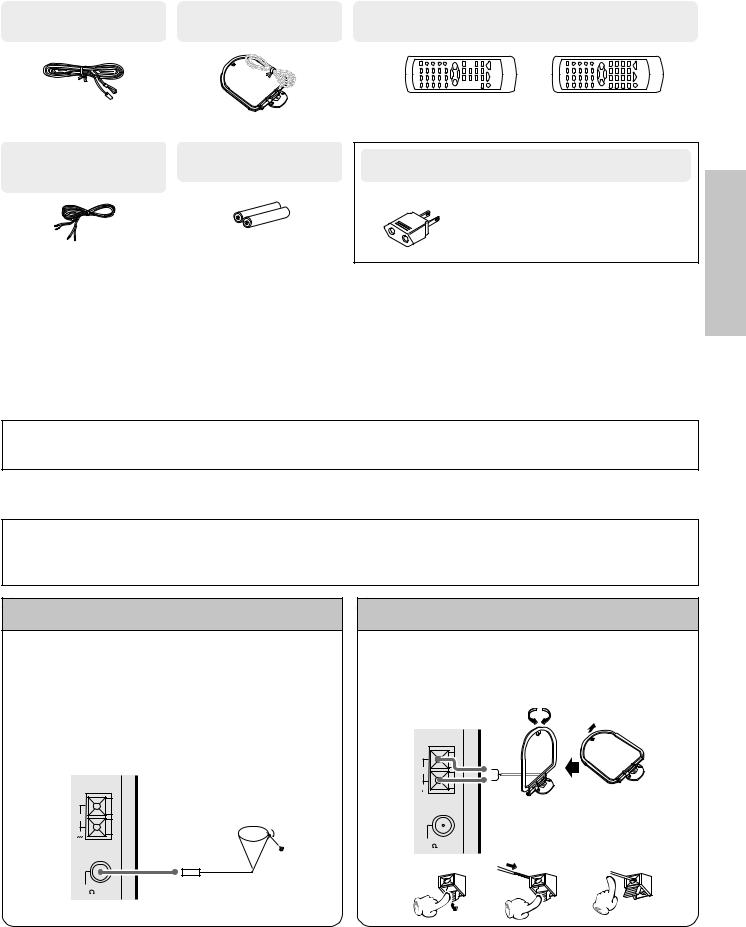
Accessories
FM indoor antenna |
AM loop antenna |
Remote control unit |
(1) |
(1) |
(1) |
Speaker cords |
Batteries (R6/AA) |
NV-301 (2) |
(2) |
NV-701 (6) |
|
(Speaker cords are provided in the speaker package. Be sure to check that the correct lengths have been provided.)
RC-NV301 |
RC-NV701 |
RC-NV301E |
RC-NV701E |
(For NV-301) |
(For NV-701) |
AC plug adaptor (1)
Use to adapt the plug on the power cord to the shape of the wall outlet. (Accessory only for regions where use is necessary.)
Unpacking
Unpack the unit carefully and make sure that all accessories are put aside so they will not be lost.
Examine the unit for any possibility of shipping damage. If your unit is damaged or fails to operate, notify your dealer immediately. If your unit was shipped to you directly, notify the shipping company without delay. Only the consignee (the person or company receiving the unit) can file a claim against the carrier for shipping damage.
We recommend that you retain the original carton and packing materials for use should you transport or ship the unit in the future.
Keep this manual handy for future reference.
When unpacking the main unit
Plastic protective adhesives have been applied to the front panel of the main unit to prevent minor scratches to the front panel during shipping. Please remove these adhesives before using this unit.
section Preparation
Connection of the system accessories
CAUTION Note on Connection
Connect the components as shown in the diagrams. Do not plug the power cord into a power outlet until connections are complete. The rear panel configuration varies depending on the models (countries or area).
FM indoor antenna
The accessory antenna is for temporary indoor use only. For stable signal reception we recommend using an outdoor antenna. Remove the indoor antenna if you connect one outdoors.
1Connect to the antenna terminal.
2Locate a position providing good reception.
3Fix the antenna in place.
AM
GND
FM 75
AM loop antenna
The supplied antenna is for indoor use. Place it as far as possible from the main unit, TV sets, speaker cords, and the power cord, and set it in the direction that provides the best reception.
AM
GND
Assemble
FM 75
1 |
2 |
3 |

6
Connecting the speakers
System connection
When connecting the speakers, be sure to keep in mind the following points regarding speaker connection.
÷Never short-circuit the “+” and “–” speaker cords.
÷If the left and right speaker connections or the “+” and “–” polarity are inverted, the sound will be unnatural with unclear positioning of musical instruments, etc. Be sure to connect the transparent cord and striped cord of the speaker cable to the matching terminals on the speakers and the main unit.
÷(NV-701 only) When all connections are complete, be sure to perform the “Setting up for surround sound”
operations to ensure the best possible surround sound from your system. |
) |
Preparation section
|
Main Unit |
|
Surround speaker system (NV-701 only) |
||
1 |
2 |
3 |
4 |
|
|
|
|
|
|
Speaker cords are supplied with this unit. Use the 2 m (6 |
|
|
|
|
|
ft.) speaker cords for the front and center speakers, the 8 |
|
Twist |
|
|
|
m (26 ft.) speaker cords for the surround speakers, and the |
|
|
|
|
|
3 m (10 ft.) speaker cord for the subwoofer. |
|
|
|
|
|
Be sure to match the colored terminals on the speakers |
|
|
Speaker Unit |
|
with the similarly labeled terminals on the main unit as |
||
|
|
|
|
follows: |
|
1 |
2 |
3 |
4 |
Front Right speaker: RED |
|
|
|
|
|
Front Left speaker: BLUE |
|
|
|
|
|
Center speaker: GREEN |
|
Twist |
|
|
|
Surround Right speaker: ORANGE |
|
|
|
|
Surround Left speaker: GRAY |
|
|
|
|
|
|
Subwoofer: BROWN |
|
Front speakers (NV-301 only) |
|
Front Speakers |
|||
|
(Right) |
(Left) |
|||
Speaker (right)
– |
+ |
Speaker (left)
– |
+ |
Speaker cord
SPEAKERS |
|
(6 – 16 |
) |
R |
L |
+ |
|
– |
|
Center
Speaker
+ |
– |
R L
GREEN RED BLUE
CENTER FRONT
+ 

–
R |
L |
BROWN |
ORANGE |
GRAY |
|
SURROUND |
SUBWOOFER |
|
(Right) |
(Left) |
Subwoofer |
Surround Speakers
System connection 7
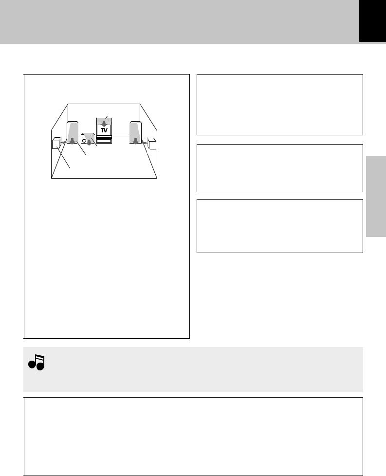
Speaker placement in a multichannel home theater setup
Center speaker
Subwoofer
Front speaker
Surround speaker
Front speakers: Place to the front left and right of the listening position at equal distances from both the unit and the listening position. Front speakers are required for all surround modes.
Center speaker: Place front and center. This speaker stabilizes the sound image and helps recreate more natural sound motion.
Surround (rear) speakers: Place to the direct left and right, or slightly behind, the listening position at even heights approximately 1 meter (3.5 ft.) above the ears of the listeners. These speakers recreate rear sound motion and atmosphere, and are required for surround playback. Subwoofer: Reproduces deep bass and other low frequency sounds.
By performing the “Surround Options” setup operations, this unit makes automatic adjustments to account for the way the speakers have been set up in order to deliver the best possible surround sound. )
CAUTION
(For U.S.A., U.S.-Military and Canada)
Be sure to adhere to the following or proper ventilation will be blocked causing damage or fire hazard.
÷Do not place any objects impairing heat radiation onto the top of this unit.
Speaker and TV installation
Themagnetin thespeakersmaycausecolorirregularity if set on the TV. If this occurs, place the speaker farther away from the TV set.
Malfunction of the microcomputer
If operation is not possible or an erroneous display appears even though all connections have been made properly, reset the microcomputer. Refer to “In case of
difficulty”. |
¨ |
section Preparation
1.Be sure to insert all connection cords securely. If connections are not secure, the sound may not be
produced or noise may interfere.
Notes 2.Before plugging or unplugging a connection cord, be sure to unplug the power cord from the wall AC outlet. If connection cords are plugged or unplugged with the power cord left plugged in, malfunction or damage may result.
CAUTION
Be sure to adhere to the following or proper ventilation will be blocked causing damage or fire hazard.
•Do not place any objects impairing heat radiation onto the top of unit.
•Do not place a speaker or any other object next to the ventilation holes on the left side of the main unit. For proper ventilation, be sure to provide sufficient space on the left side of the main unit.
•Leave a space around the unit (from the largest outside dimension including projection) equal or greater than, shown below.
Top panel : 50 cm |
Side panel : 10 cm |
Back panel : 10 cm |
8 |
System connection |
|
Connection with other components (optional or commercially-available equipment)
CAUTION Note on Connection
Connect the components as shown in the diagrams. Do not plug the power cord into a power outlet until connections are complete. The rear panel configuration varies depending on the models (countries or area).
 When an external system component is connected, please read the instruction manual of the component Note as well.
Preparation section
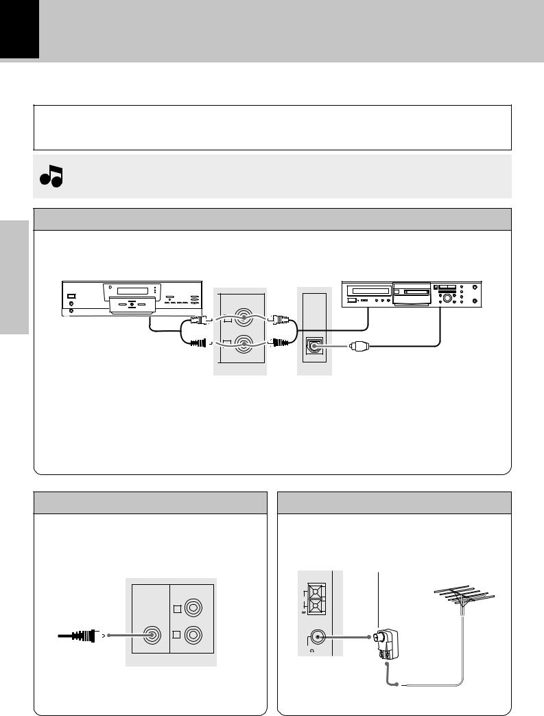
MD recorder, DVD player, VCR, or analog turnable (NV-301 only)
DVD player/VCR/analog |
|
|
turntable (P-110/optional) |
MD recorder |
|
MD/DVD |
OPTICAL |
|
|
OUT |
|
L |
Audio output |
Digital input |
Audio output |
|
|
R |
|
|
|
Optical-fiber cable |
|
When making connections
÷Make connections to the MD/DVD jacks using a commercially available audio cable.
÷Be sure to match the colors of the plugs with the colors of the jacks for correct right (red) and left (white) channel matching.
÷Make connections to the OPTICAL OUT optical jack using a commercially available digital optical cable to an MD recorder or other digital recording device for digital recording of CDs played on this unit.
Subwoofer (NV-301 only)
Connect a subwoofer (optional) for powerful low frequency sounds.
SUPER MD/DVD
WOOFER
PRE OUT
L
R
FM outdoor antenna
Lead the 75Ω coaxial cable connected to the FM outdoor antenna into the room and connect it to the FM 75Ω
terminal. |
Use a commercially-available antenna |
|
|
|
adapter (a small-sized model). |
AM
GND
FM 75
System connection 9
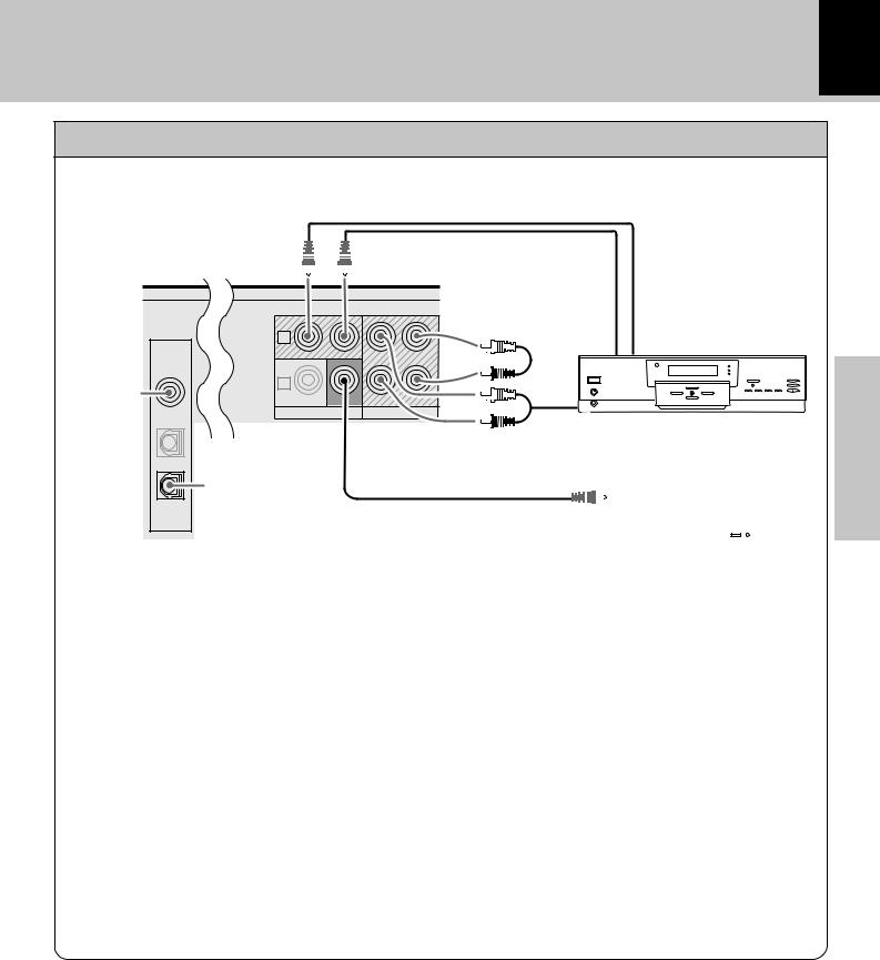
VCR, MD/CD recorder, or analog turntable (NV-701 only)
The VIDEO 1 jacks can be used for connection of a VCR or similar component that features audio and video input and output capability.
|
DIGITAL |
|
VIDEO 1 |
|
COAX. IN |
For VIDEO 1 |
|
digital audio |
VIDEO 2 |
input |
OPT. IN |
CD
OPT. OUT
|
Video input |
Video output |
1 |
Audio input |
VCR |
|
2 |
|
|
|
|
PLAY IN |
MONITOR |
PLAY IN |
REC OUT |
|
OUT |
||||
|
|
|
VIDEO |
AUDIO–VIDEO 1 |
Audio output
TV
For digital audio |
To video input of TV |
|
|
|
|
|
||||
|
|
|
|
|
||||||
output of CDs |
|
|
|
|
|
|
|
|
|
|
|
|
|
|
|
|
|
|
|
|
|
|
|
|
|
|
|
|
|
|
|
|
|
|
|
|
|
|
|
|
|
|
|
|
|
|
|
|
|
|
|
|
|
|
|
|
|
|
|
|
|
|
|
|
|
|
|
|
|
|
|
|
|
|
|
|
|
|
|
|
|
|
|
|
|
|
|
section Preparation
When making connections to a VCR:
÷For complete video connection, use commercially available video cables to make connections from the video output jack on the VCR to the VIDEO 1 PLAY IN jack, from the video input jack on the VCR to the VIDEO 1 output jack (located above the MONITOR OUT jack), and from the VIDEO MONITOR OUT jack to a TV or monitor.
÷Make audio connections from the audio output jacks on the VCR to the AUDIO – VIDEO 1 PLAY IN jacks and from the audio input jacks on the VCR to the AUDIO – VIDEO 1 REC OUT jacks using commercially available audio cables.
÷Be sure to match the colors of the plugs with the colors of the jacks for correct right (red) and left (white) channel matching.
÷For greatly improved sound, make connections to the DIGITAL VIDEO 1 COAX. IN jack using a commercially available
coaxial cable if the component you are making connections to features digital audio output from a coaxial jack.
When making connections to an MD or CD recorder:
÷Make audio connections from the audio output jacks on the MD or CD recorder to the AUDIO – VIDEO 1 PLAY IN jacks and from the audio input jacks on the MD or CD recorder to the AUDIO – VIDEO 1 REC OUT jacks using commercially available audio cables.
÷Do not make any connections to the VIDEO 1 PLAY IN and output jacks.
÷If digital connections are made to the DIGITAL VIDEO 1 COAX. IN jack, it is also recommended to make connections to the analog AUDIO – VIDEO 1 PLAY IN jacks.
÷Make connections from the DIGITAL CD OPT. OUT jack to the corresponding input jack on the MD or CD recorder for digital recording of CDs played on this unit.
10 |
System connection |
|
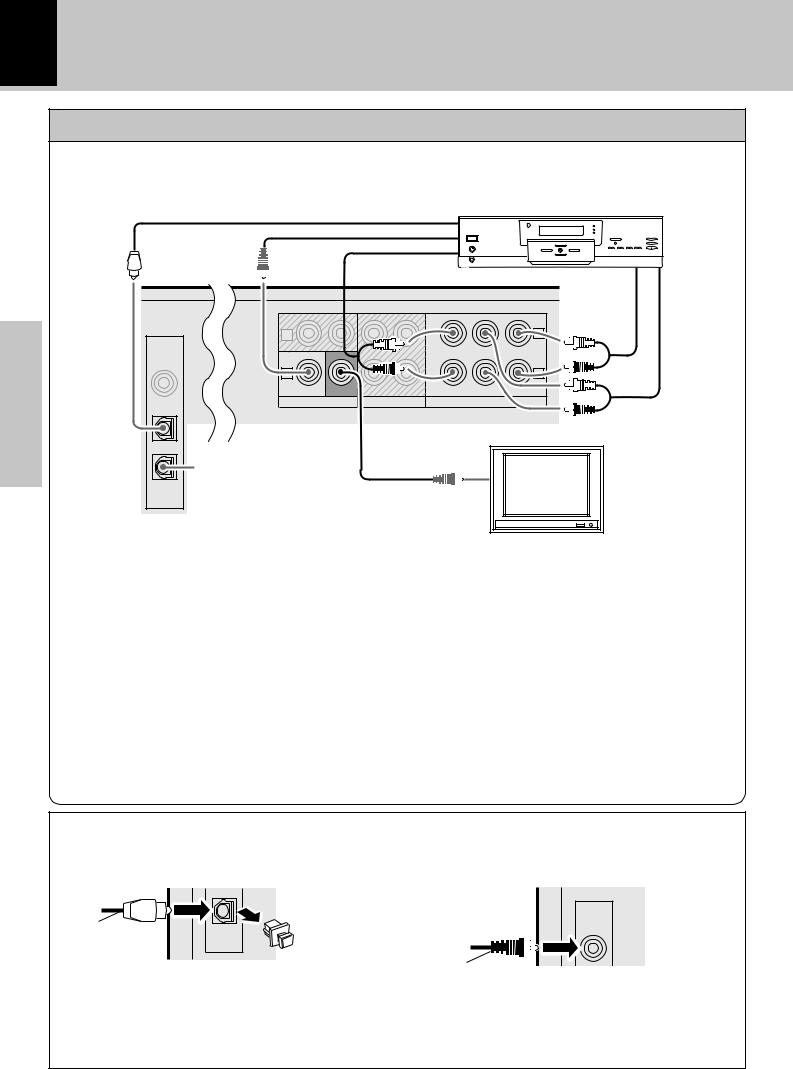
DVD player (NV-701 only)
Preparation section
The VIDEO 2 jacks can be used for connection of a DVD player or similar component that features audio and/or video output capability.
DVD player
Optical-fiber cable |
Digital output |
Video output
|
|
|
Audio output |
|
|
|
|
|
|
|
|
(FRONT) |
|
|
Audio output |
Audio output |
|
|
|
|
|
|
|
|
||
|
|
|
|
|
|
|
(SURROUND) |
(CENTER/ |
|
|
|
|
|
|
CENTER |
|
SUBWOOFER) |
|
|
|
|
|
|
|
|
|
DIGITAL |
1 |
|
|
|
|
|
L |
|
|
|
|
|
|
|
|
|
|
VIDEO 1 |
|
|
|
|
|
|
|
|
COAX. IN |
2 |
|
|
|
|
|
R |
|
|
|
|
|
|
|
|
||
|
PLAY IN |
MONITOR |
PLAY IN |
REC OUT |
FRONT |
SUBWOOFER |
SURROUND |
|
|
|
OUT |
|
|
|
|
|
|
VIDEO 2 |
VIDEO |
|
AUDIO–VIDEO 1 AUDIO–VIDEO2 / 6 CH INPUT |
|
||||
OPT. IN |
|
|
|
|
|
|
|
|
TV
|
To video input of TV |
|
For digital audio |
CD |
output of CDs |
OPT. OUT
When making audio connections to a DVD player or similar component:
÷For complete video connection, use commercially available video cables to make connections from the video output jack on the DVD player to the VIDEO 2 PLAY IN jack, and from the VIDEO MONITOR OUT jack to a TV or monitor.
÷When making analog connections from a DVD player that only features right and left channel stereo output, make connections to the AUDIO – VIDEO 2/6 CH INPUT FRONT R and L jacks respectively. When making this type of connection, do not make connections to the CENTER, SUBWOOFER, or SURROUND R/L jacks.
÷When you are making connections from a DVD player that features internal decoding or when the digital signal is routed through a decoder for full 6 channel discreet audio output, make connections from the output jacks on the DVD player or decoder to the corresponding AUDIO – VIDEO 2/6 CH INPUT jacks .
÷For greatly improved sound, make connections to the DIGITAL VIDEO 2 OPT. IN jack using a commercially available optical-fiber cable.
÷If digital connections are made to the DIGITAL VIDEO 2 OPT. IN jack, it is also recommended to make connections to the appropriate analog AUDIO – VIDEO 2/6 CH INPUT jacks.
About the DIGITAL jacks on this unit |
|
|
When using the DIGITAL OPT. (optical) jacks, remove |
(NV-701 only) When using the DIGITAL VIDEO 1 |
|
the cap and plug in the optical-fiber cable. |
COAX. IN jack, insert the coaxial cable firmly into the |
|
|
|
jack. |
|
|
DIGITAL |
Optical-fiber cable |
CD |
VIDEO 1 |
COAX. IN |
||
|
OPT. OUT |
|
|
Cap |
|
Coaxial audio cable
÷Insert the optical-fiber cable straight into the connector until it clicks.
÷Be sure to attach the protection cap when the connector is not used.
÷Never bend or bundle up the optical-fiber cable.
Controls and indicators |
11 |
|
|
Main unit
HI-FI COMPONENT SYSTEM
section Preparation
|
U |
ME CO |
NT |
R |
MULTI CONTROL |
L |
|
|
O |
||
O |
|
|
|
|
|
V |
|
|
|
|
L |
SET ENTER
MENU
DEMO
STANDBY
STANDBY
CD
ON/STANDBY
DISC SKIP
TUNER |
POWER |
BAND
OPEN/CLOSE
TAPE
PHONES
MD/DVD
changer
VIDEO/6ch IN

12
1Display |
# |
2TAPE (™£) key |
• |
Press to select the cassette deck and start playback.
3TUNER (BAND) key |
⁄ |
Press to select the tuner and switch the receiving band.
4CD (6) key |
§ |
Press to select the CD input and start playback.
|
5VOLUME CONTROL knob |
¢ |
|
|
Use to adjust the volume. |
|
|
|
6 SET (÷) key |
*fi |
|
|
Press to set items when using the MULTI CONTROL |
||
|
setting mode. |
|
|
|
When the TAPE input is selected, press to start |
||
|
|||
section |
recording. Pressing this key while recording stops it |
||
after creating a non-recorded space (blank) of about 4 |
|||
|
|||
|
seconds. |
|
|
Preparation |
7MULTI CONTROL (4/¢) keys |
|
|
*¶ª⁄ |
|
||
|
|
||
|
Use these keys to select optimum modes according to |
||
|
the desired operations. |
|
|
|
When the CD input is selected, these keys are used to |
||
|
skip tracks. |
|
|
|
When the TUNER input is selected, these keys are used |
||
|
|||
|
to select a station. |
|
|
|
When the TAPE input is selected, these keys are used |
||
|
to fast forward or rewind the tape. |
|
|
|
8ENTER key |
* |
|
Press to enter settings and perform functions when using the MULTI CONTROL setting mode.
When power is in the standby mode:
Used for displaying the time. (If this key is pressed while a timer operation is set, the timer icon and the timer reservation setting mode appear in the display, then the display returns to the previous condition.)
|
Controls and indicators |
|
97 (stop) key |
¶ª |
|
Operation key for the CD player and cassette deck. |
|
|
0MENU (DEMO) key |
4* |
|
Switches the displayed information. Press to switch the MULTI CONTROL setting mode on and off.
When power is in the standby mode:
Use to turn the demonstration on and off.
! |
|
|
(ON/STANDBY) key |
¢ |
|
|
|||
|
||||
|
|


 (POWER) key (For U.S.A.)
Press to turn the power ON and put in STANDBY.
STANDBY indicator
The indicator lights up when the power is set to the standby mode.
@ DISC SKIP key |
§¶ |
The disc for playback (or recording) is selected. This is also used to rotate the disc tray when loading CDs onto the disc tray.
# OPEN/CLOSE (0) key |
§ |
The disc tray is opened and closed. |
|
$PHONES jack |
¢ |
For connection of headphones (optional). |
|
%MD/DVD key (NV-301 only) |
¢ |
Press to select input from the component connected to the MD/DVD jacks on the rear panel.
VIDEO/6ch IN key (NV-701 only)
Press to switch between selection of the components connected to the VIDEO 1 and VIDEO 2 related jacks on the rear panel.
^ Disc tray |
§ |
Three discs can be stored. |
|
& Cassette holder |
• |
Press PUSH OPEN to load or remove a tape. |
|
|
|
|
|
|
|
|
|
|
|
|
|
|
|
|
|
Controls and indicators |
13 |
||
|
|
|
|
|
|
|
|
|
|
|
|
|
|
|
|
|
|
|
|
|
Display |
|
|
The displays given in this manual are approximations only. They may differ from what |
|||||||||||||||
|
|
|
actually appears on the display. |
||||||||||||||||
|
|
|
|
|
|
|
|
|
|
|
|
|
|
|
|
|
|
|
|
|
|
|
|
|
|
|
|
|
|
|
|
|
|
|
|
|
|
|
|
|
|
|
|
|
|
|
|
|
|
|
|
|
|
|
|
|
|
|
|
|
|
|
|
|
|
|
|
|
|
|
|
|
|
|
|
|
|
|
|
|
|
|
|
|
|
|
|
|
|
|
|
|
|
|
|
|
|
|
|
|
|
|
|
|
|
|
|
|
|
|
|
|
|
|
|
|
|
|
|
|
|
|
|
|
|
|
|
|
|
|
|
|
|
|
|
|
|
|
|
|
|
|
|
|
|
|
|
|
|
|
|
|
|
|
|
|
|
|
|
section Preparation
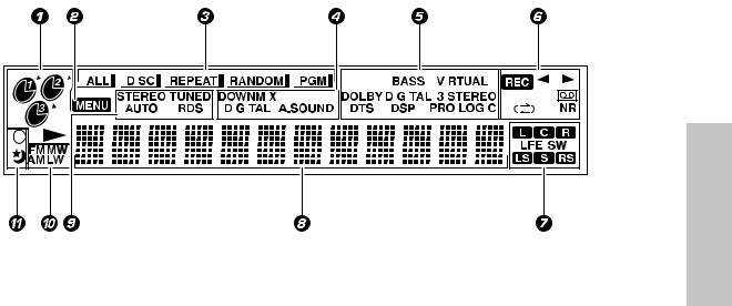
1 CD player indicators |
6 Cassette deck-related indicators |
Indicate which disc trays contain discs, which disc is currently selected as well as play and pause indications.
2 MENU indicator
The unit is in the MULTI CONTROL setting mode.
3 CD playback mode indicators
ALL: ALL disc playback is selected. DISC: Single disc playback is selected.
REPEAT: Repeat playback is being performed. PGM: Program playback is being performed. RANDOM: Random playback is being performed.
4 Audio input selection indicators (NV-701 only)
DOWNMIX: A multichannel audio source is being downmixed for stereo output.
DIGITAL: The digital audio input from a connected component is selected.
A.SOUND: The audio signal format from a connected component is automatically selected.
5 Sound mode indicators
The following indicators light for NV-301 only BASS: The bass is being emphasized using the Exbass function.
The following indicators light for NV-701 only VIRTUAL: The Virtual surround mode is selected.
DOLBY DIGITAL: Dolby Digital processing is selected.
3 STEREO: The 3 STEREO surround mode is selected.
DTS: DTS processing is selected.
DSP: One of this unit's DSP modes is selected. PRO LOGIC: A Dolby Pro Logic source is being played back.
Indicate the play/record status, the reverse mode, the tape playback direction, and whether Dolby NR (noise reduction) is being used.
7 Multichannel audio indicators (NV-701 only)
Indicate the active audio channels present in a source or the type of playback being performed. L: Front left channel
C: Center surround channel R: Front right channel
LFE: Low Frequency Effects (included in 5.1 channel sound tracks)
SW: Subwoofer channel LS: Left surround channel
S: Monaural rear surround channel RS: Right surround channel
8 Character information display
Displays the MULTI CONTROL setting items, input selection, tuner frequency, volume level, etc.
9 Tuner broadcast indicators
Depending on the region, not all indicators appear. STEREO: The broadcast is being received in stereo. TUNED: A station has been preset in memory. AUTO: Automatic preset tuning is being performed. RDS: (For U.K. and Europe) A station that features RDS functions is tuned.
0 Tuner band indicators
Indicates the currently selected broadcast band. Depending on the region, not all band indicators appear.
! Timer indicators
Indicate a timer reservation has been set.
14
Controls and indicators
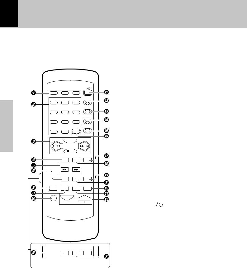
Remote control unit (RC-NV301 / RC-NV301E)
The keys on the remote control unit with the same names as on the main unit have the same function as the keys on the main unit.
4 BACK key |
* |
POWER
|
DISC 1 |
DISC 2 |
DISC 3 |
|
|
|
|
|
CD |
|
1 |
2 |
3 |
|
section |
|
|
|
TUNER/BAND |
4 |
5 |
6 |
|
|
|
|
|||
|
|
|
|
TAPE |
Preparation |
7 |
8 |
9 |
|
|
DISC SKIP |
MD/DVD |
||
|
|
|
|
|
|
0 |
+10 |
MENU |
|
|
|
MULTI CONTROL |
|
|
|
|
P.CALL |
|
|
|
|
|
AUTO |
|
|
|
BACK |
SET |
ENTER |
 TUNING
TIME DISP. TEXT DISP. EX.BASS
SLEEP TIMER REPEAT RANDOM
MUTE VOLUME
TIME DISP. TEXT DISP. EX.BASS
PTY |
RDS DISP. |
1 DISC SELECTOR keys §¶
Use to select the disc for playback (or recording).
2 Numeric keys |
¶ |
Used as number keys when the input is CD or TUNER.
3 MULTI CONTROL keys *¶ª⁄
P.CALL 4/¢(skip) keys |
¶⁄ |
DISC SKIP key |
§¶ |
7/AUTO key |
¶ª⁄ |
Press in the MULTI CONTROL setting mode to
return to a previous step.
5 TUNING (1/¡) keys ¶¤
When the CD input is selected, press to fast forward or backward the disc.
When the TUNER input is selected, press to tune in a station.
6 TIME DISP. key |
¶ |
Press to switch the time information on the CD player unit.
PTY key (For U.K. and Europe) |
e |
This is used to specify the program type when searching |
|
for a station. |
|
7 TEXT DISP. key |
t |
Press to switch the text information recorded in a CD |
|
TEXT disc. |
|
RDS DISP. key (For U.K. and Europe) |
w |
The display contents are switched during reception of RDS broadcasts.
8 SLEEP key |
O |
||
Press to set the sleep timer. |
|
||
9 TIMER key |
P |
||
Press to set the timer programming mode. |
|||
0 MUTE key |
° |
||
This is used to mute the sound temporarily. |
|||
!POWER ( |
|
) key |
¢ |
|
|||
|
|||
@CD (6) key |
§ |
||
#TUNER/BAND key |
⁄ |
||
$TAPE (™£) key |
• |
||
%MD/DVD key |
¢ |
||
^MENU key |
* |
||
& ENTER key |
* |
||
* SET key |
*› |
||
( EX.BASS key |
° |
||
Press to enhance the bass during audio playback. |
|||
) RANDOM key |
q |
||
For CD playback, switching is executed between random |
|||
playback and normal playback. |
|
||
¡ REPEAT key |
· |
||
Used for repeated playback of a CD. |
|
||
™VOLUME keys |
¢ |
||
Use to adjust the volume.
When the CD or TAPE input is selected, press to stop playback.
When the TUNER input is selected, press to select automatic tuning.
Controls and indicators 15
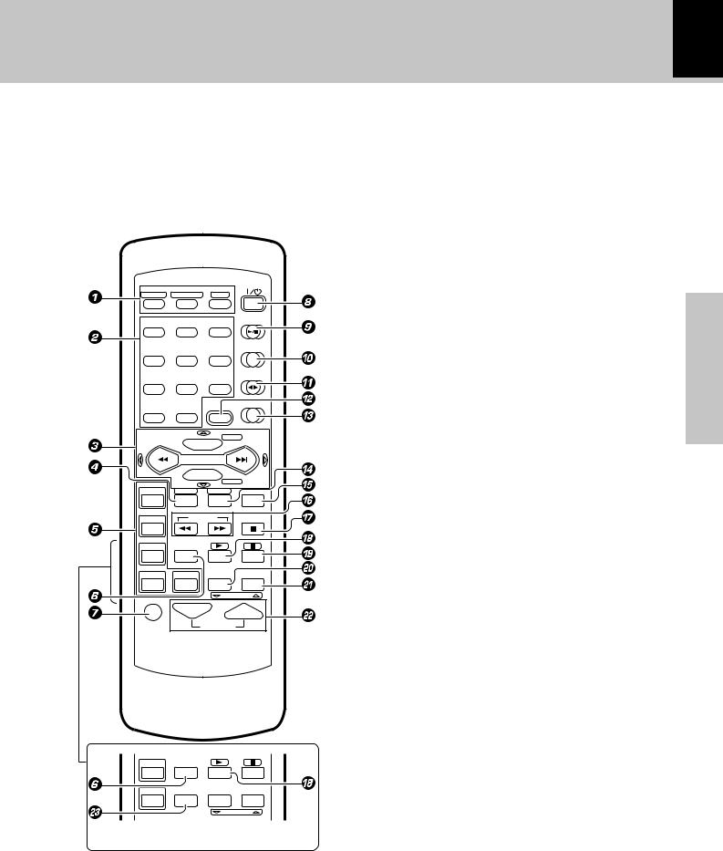
Remote control unit (RC-NV701 / RC-NV701E)
The keys on the remote control unit with the same names as on the main unit have the same function as the keys on the main unit.
Functions listed in brackets [ ] can be set up to be used with the components you have connected to this unit.
For more details, see “Remote operation of other components” |
Y |
|
|
|
POWER |
INPUT SEL. |
TV SEL./TITLE |
QUIT |
|
DISC 1 |
DISC 2 |
DISC 3 |
|
|
|
|
CD |
1 |
2 |
3 |
|
|
|
|
TUNER/BAND |
4 |
5 |
6 |
|
|
|
|
TAPE |
7 |
8 |
9 |
|
|
|
|
VIDEO/6chIN |
0 |
+10 |
MENU |
|
|
|
CD-R |
|
|
DISC SKIP |
|
|
|
MULTI CONTROL |
|
|
|
P.CALL |
|
|
|
BACK |
|
|
POWER |
|
CD |
|
|
|
|
|
TV |
OSD |
RETURN |
|
|
SETUP |
SET |
ENTER |
VCR |
TUNING |
AUTO |
|
DVD |
TIME DISP. |
|
|
|
|
|
LSTN M. |
|
|
TEXT DISP. |
RANDOM |
CD-R |
CABLE |
REPEAT |
|
|
|
CHANNEL |
|
MUTE |
|
VOLUME |
|
1 DISC SELECTOR keys §¶
Use to select the disc for playback (or recording).
[INPUT SEL]
Use to select/change the input on a TV, VCR, etc.
[TV SEL/TITLE]
Use to change the TV to the TV mode. Use to display the title menu when controlling a DVD player.
[QUIT]
Use to quit operation of a TV, VCR, DVD player, CD recorder, etc.
2 Numeric keys |
¶ |
Used as number keys when the input is CD or TUNER.
[Numeric keys]
Use to enter numbers for use with a TV, VCR, DVD player, CD recorder, etc.
3 MULTI CONTROL keys *¶ª⁄ P.CALL 4/¢(skip) keys ¶⁄ [Skip tracks/ 2/3cursor control ]
Use to skip through tracks on a CD recorder or navigate right and left on a DVD player menu screen.
DISC SKIP key |
§¶ |
[CD-R/5cursor control] |
|
Use to select the CDR functions of a CD recorder or navigate up on a DVD player menu screen.
BACK key |
* |
Press in the MULTI CONTROL setting mode to return to a previous step.
[CD/° cursor control]
section Preparation
Use to select the CD functions of a CD recorder or navigate down on a DVD player menu screen.
4 SETUP key |
Y |
DVD TIME DISP.
PTY |
RDS DISP. |
LSTN M. |
TEXT DISP.
CD-R TIMER REPEAT RANDOM
CHANNEL
Press to set up the remote control unit to control other components.
[OSD]
Use to open the setup menu of a DVD player, etc.
5[TV, VCR, DVD, CD-R source power keys]Y
Use to switch the power of your other components on and off. There are separate keys that can be set up for control of each component.
[CABLE power key] (For U.S.A.)
Use to switch the cable box on and off. |
|
6 TIME DISP. key |
¶ |
Press to switch the time information on the CD player unit.
PTY key (For U.K. and Europe) |
e |
This is used to specify the program type when searching for a station.

16
Controls and indicators
Preparation section
7 MUTE key |
° |
||
This is used to mute the sound temporarily. |
|
||
8POWER ( |
|
) key |
¢ |
|
|||
|
|||
9CD (6) key |
§ |
||
0TUNER/BAND key |
⁄ |
||
!TAPE (™£) key |
• |
||
@MENU key |
* |
||
[MENU] |
|
||
Use to display the menu screen when using a DVD player, etc.
#VIDEO/6ch IN key |
¢ |
$ SET key |
*fi |
[RETURN] |
|
Use to return to a previous screen on DVD player menu screen.
% ENTER key |
* |
[ENTER/Play] |
|
Use to enter settings in a TV or DVD player, etc., or
also start playback of a VCR, CD recorder, etc.
^ TUNING (1/¡) keys ¶¤
When the CD input is selected, press to fast forward or backward the disc.
When the TUNER input is selected, press to tune in a station.
[Fast forward and reverse]
Use to perform fast forward and reverse scanning
with a VCR, DVD player, or CD recorder.
&AUTO (7) key ¶ª⁄
When the CD or TAPE input is selected, press to stop playback.
When the TUNER input is selected, press to select automatic preset tuning.
[Stop]
Use to stop playback of a VCR, DVD player, or CD recorder.
* TEXT DISP. key |
t |
Press to switch the text information recorded in a CD TEXT disc.
RDS DISP. key (For U.K. and Europe) w
The display contents are switched during reception of RDS broadcasts.
[3] (play)
Use to start playback of a VCR, DVD player, or CD recorder.
( LSTN M. key |
R |
Press to select an audio effect.
[8] (pause)
) REPEAT key |
· |
Used for repeated playback of a CD. |
|
[CHANNEL °] |
|
Use to select lower channel selections when |
|
controlling a TV, VCR, etc. |
|
¡ RANDOM key |
q |
For CD playback, switching is executed between random playback and normal playback.
[CHANNEL 5]
Use to select higher channel selections when |
|
controlling a TV, VCR, etc. |
|
™VOLUME keys |
¢ |
[volume] |
|
Use to control the volume of a TV, etc. |
|
£ TIMER key (For U.K. and Europe) |
P |
Press to set the timer programming mode. |
|
Use to pause playback of a VCR, DVD player, or CD recorder.
|
Operation of the remote control unit |
|
17 |
||
|
|
|
|
|
|
|
|
|
|
|
|
|
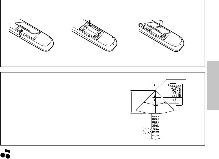
Loading batteries |
|
|
|
|
|
1 Remove the cover. |
2 Insert batteries. |
3 Close the cover. |
||
÷Insert two R6 (“AA”-size) batteries following the polarity indications.
Operation
Plug the power cord into the mains power outlet and press the POWER ( 

 ) key of the remote control unit to turn the power ON. After the power has been turned ON, press the desired key.
Toputthepowerinstandby,pressthePOWER ( 

 ) key again. The power mode enters the standby mode and the STANDBY indicator lights up.
|
Remote |
Operating range |
sensor |
(approx.) |
|
6m |
|
30˚ |
30˚ |
÷When pressing more than one remote control key successively, press the keys securely and leave an interval of 1 second or more between the key presses.
section Preparation
 1.The provided batteries are intended for use in operation checking, and their service life may be short. Notes 2.When the remote controllable distance becomes short, replace both of the batteries with new ones.
3.If direct sunlight or the light of a high-frequency fluorescent lamp (inverter type, etc.) is incident to the remote sensor, malfunction may occur. In such a case, change the installation position to avoid malfunction.
18 Operation of the MULTI CONTROL setting mode
Preparation section
The MULTI CONTROL keys make it possible to perform a number of functions in a simple procedure.
When the MENU key is pressed, items appear in the display according to the MULTI CONTROL key operation, so you can select the desired mode more intuitively.
You can also use the 4/¢keys on the remote control unit in the same manner as the MULTI CONTROL keys on the main unit.
Main unit |
|
|
Remote control unit |
|
|
||
MULTI CONTROL |
|
|
MD/DVD |
|
|
VIDEO/6chIN |
|
|
0 |
+10 |
MENU |
|
0 |
+10 |
MENU |
|
|
|
|
|
|
|
CD-R |
SET |
ENTER |
DISC SKIP |
|
|
DISC SKIP |
||
MULTI CONTROL |
|
|
MULTI CONTROL |
||||
|
|
P.CALL |
|
|
P.CALL |
||
|
|
|
AUTO |
|
|
|
BACK |
|
MENU |
|
|
|
POWER |
|
CD |
|
BACK |
SET |
ENTER |
|
|
||
|
TV |
OSD |
RETURN |
||||
|
DEMO |
|
|
|
|
SETUP |
SET ENTER |
|
|
|
|
|
|
|
|
|
|
NV-301 |
|
|
NV-701 |
||
MULTI CONTROL key operation
1 Press the MENU key to enter the MULTI CONTROL setting mode.
2 Select an operation mode by pressing the MULTI CONTROL keys repeatedly . 3 Set items by pressing the SET and ENTER keys as described for each item.
Display examples
The following items can be selected by pressing the MULTI CONTROL keys.
 “CD Program Play” (This item only appears when CD input is selected and playback is stopped.) “Recording Options” (Thisitemonlyappearswhenatapeisinthetapeholder,anddoesnotappear
when TAPE input is selected.)
“Tape Options”
“Audio Options”
“Clock Options”
 “Surround Options” (NV-701 only)
÷To cancel the MULTI CONTROL setting mode, press the MENU key again.
÷Press the BACK key on the remote control unit to return to the previous step and restart operation from there. (The BACK key is inoperative once the message “Press “ENTER” to - - -” has been scrolled.)
÷Keys on the remote control unit that have the same name as keys on the main unit perform the same functions.
÷Depending on the source selected, some items may not be displayed.
The volume control can be used to control the current function while in the MULTI CONTROL setting mode.
Clock adjustment |
19 |
|
|
This unit incorporates a clock function. It is necessary to set the correct time before using the timer functions. The time can be displayed only while the power is in standby.
|
|
|
|
|
|
|
|
|
|
|
Thefollowingitemscanbeselectedbypressingthe |
||||||||||||||
|
1 Select “Clock Options”. |
|
|
|
MULTI CONTROL keys repeatedly. |
|
|
|
|||||||||||||||||
|
|
|
|
|
|
|
(“CD Program Play”) |
|
|
|
|
|
|||||||||||||
|
|
|
|
|
|
|
|
|
|
|
|
|
|
|
|
|
|
|
|||||||
|
|
|
|
|
|
|
|
|
|
|
|
|
|
(“Recording Options”) |
|
|
|
|
|||||||
|
|
|
|
MULTI CONTROL |
|
|
|
|
|
|
“Tape Options” |
|
|
|
|
|
|||||||||
|
|
MENU |
|
|
SET |
|
|
|
|
|
|
|
|
|
|
|
|||||||||
|
|
DEMO |
|
|
|
|
|
|
|
|
|
|
“Audio Options” |
|
|
|
|
|
|||||||
|
|
|
|
|
|
|
|
|
|
|
|
|
|
|
|
|
|
|
|
|
|
|
|
|
|
|
|
|
|
|
|
|
|
|
|
|
|
|
|
“Clock Options” |
|
|
|
|
|
|
|
||||
|
|
|
|
|
|
|
|
|
|
|
|
|
|
“Surround Options” (NV-701 only) |
|||||||||||
|
|
|
|
|
|
|
|
|
|
|
|
|
|
||||||||||||
|
2 Select “Adjust Time”. |
|
|
|
|
|
|
+“Clock Options” is scrolled in the display |
|||||||||||||||||
|
|
|
|
|
|
|
|
Clock Option |
|
|
|
||||||||||||||
|
|
|
|
|
|
|
|
|
|
|
|
|
|
|
|
|
|
||||||||
|
|
MULTI CONTROL |
|
|
|
|
|
|
|
|
|
|
|
|
|
|
|
|
|
|
|||||
|
|
|
|
|
|
|
|
|
|
|
|
|
|
|
|
|
|
|
|
||||||
|
|
|
|
|
SET |
|
|
|
|
|
|
|
|
|
|
|
|
|
|
|
|
|
|
||
|
|
|
|
|
|
|
Thefollowingitemscanbeselectedbypressingthe |
||||||||||||||||||
|
|
|
|
|
|
|
|
|
|
|
|||||||||||||||
|
|
|
|
|
|
|
|
|
|
|
MULTI CONTROL keys repeatedly. |
|
|
|
|||||||||||
|
|
|
|
|
|
|
|
|
|
|
|
|
|
“Sleep Timer” |
|
|
|
|
|
||||||
|
|
|
|
|
|
|
|
|
|
|
|
|
|
|
|
|
|
|
|||||||
|
|
|
|
|
|
|
|
|
|
|
|
|
|
|
|
|
|
|
|
|
|
|
|
||
|
3 Adjust the hour. |
|
|
|
|
|
|
“Adjust Time” |
|
|
|
|
|
|
|
|
|||||||||
|
|
|
|
|
|
|
“Timer Play” |
|
|
|
|
|
|||||||||||||
|
|
|
|
|
|
|
|
|
|
|
|
|
|
|
|
|
|
|
|||||||
|
|
MULTI CONTROL |
|
|
|
|
|
|
“Auto Power Save” |
|
|
|
|
|
|||||||||||
|
|
|
|
|
|
|
|
|
|
|
|
|
|||||||||||||
|
|
|
|
|
|
|
|
|
|
|
|
|
|
|
|
|
|
|
|
||||||
|
|
|
|
|
SET |
|
|
|
|
|
|
|
|
|
|
|
|
|
|
|
|
|
|
||
|
|
|
|
|
|
|
|
|
|
|
Example: Setting the time to 8:45 in the morning |
||||||||||||||
|
|
To decrease |
To increase |
|
|
||||||||||||||||||||
|
|
|
|
8:00 |
|
|
|
|
|
AM |
|
8:00 |
|
||||||||||||
|
|
the figure |
the figure |
|
|
|
|
|
|
|
|
|
|
|
|
|
|
|
|
|
|
||||
|
|
|
|
|
(For U.K. and Europe) |
(Other countries) |
|||||||||||||||||||
|
|
|
|
|
|
|
|
|
|
|
|||||||||||||||
|
|
|
|
|
|
|
|
|
|
|
0Ô1Ô2...13Ô14...Ô0 ... AM12ÔAM1ÔAM2... |
||||||||||||||
|
4 Adjust the minute. |
|
|
|
|
|
|
|
|
|
|
|
|
|
PM1ÔPM2...ÔAM12 ... |
||||||||||
|
|
|
|
÷ The time display starts to blink. |
|
|
|
|
|||||||||||||||||
|
|
|
|
|
|
|
|
|
|
|
|
|
|
|
|||||||||||
|
|
MULTI CONTROL |
|
|
|
÷ Press the SET key. The hour is entered and the minute |
|||||||||||||||||||
|
|
|
|
|
SET |
|
|
|
|
|
display starts to blink. |
|
|
|
|
|
|||||||||
|
|
|
|
|
|
|
|
|
|
|
|
|
|
|
|
|
|
|
|
|
|
|
|
|
|
|
|
To decrease |
To increase |
|
|
|
|
|
|
|
|
|
|
|
|
|
|
|
|
|
|
||||
|
|
|
|
8:45 |
|
|
|
|
|
AM |
|
8:45 |
|
||||||||||||
|
|
the figure |
the figure |
|
|
|
|
|
|
|
|
|
|
|
|
|
|
|
|
|
|
||||
|
|
|
|
|
(For U.K. and Europe) |
(Other countries) |
|||||||||||||||||||
|
5 Start the clock. |
|
|
|
|||||||||||||||||||||
|
|
|
|
|
|
|
|
00Ô01Ô02...59Ô00Ô01... |
|
||||||||||||||||
|
|
|
|
|
|
|
|
|
|
|
|
|
|
|
|
||||||||||
|
|
|
|
ENTER |
|
|
|
÷ Press the BACK key to return to the previous step and |
|||||||||||||||||
|
|
|
|
|
|
|
|
|
|
|
|||||||||||||||
|
|
|
|
|
|
|
|
|
|
|
|
|
restart operation from there. |
|
|
|
|
||||||||
|
|
|
|
|
|
|
|
|
|
|
|
|
|
|
|
|
|||||||||
|
|
|
|
|
|
|
|
|
|
|
÷ To set the time precisely, press the ENTER key at the |
||||||||||||||
|
|
|
|
|
|
|
|
|
|
|
|
|
same moment as a time announcement. |
||||||||||||
|
|
|
|
|
|
|
|
|
|||||||||||||||||
section Preparation
To display the time
(In standby mode or when the MD/DVD (NV-301 only) or VIDEO/6ch IN (NV-701 only) input is selected.)
ENTER
(Displayed for approximately 5 seconds)
÷The clock is reset and the clock display blinks if the power cord has been unplugged from the AC power outlet and plugged in again, or after a power failure. In this case, set the time again.
20 Setting up for surround sound (NV-701 only)
Once you have completed setting up your speakers, make sure to complete the following speaker settings to obtain and enjoy the best possible surround sound possible from this system.
Setting the configuration of the speaker system
A full surround speaker system is supplied with the NV-701, and the factory settings have been set up according to the specifications of the supplied speakers. However, if you do not connect all the speakers or use different speakers, change the settings as needed to ensure the best possible surround sound for your system.
Preparation section
If you have connected all of the supplied speakers as described on page 6, it is not necessary to perform the procedure on this page. If this is the case, proceed to “Setting speaker distances and system volume levels” on the following page.
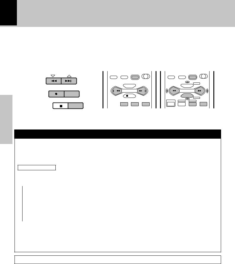
1 Select “Surround Options”.
MULTI CONTROL
MENU |
SET |
DEMO
2 Select “Speaker Selection”.
MULTI CONTROL
SET
3Set the size (or presence) of the speakers.
MULTI CONTROL
SET
4 Complete and save the settings.
ENTER
Thefollowingitemscanbeselectedbypressingthe MULTI CONTROL keys repeatedly.
 (“CD Program Play”)
(“Recording Options”) “Tape Options” “Audio Options” “Clock Options”
 “Surround Options” (NV-701 only)
+“Surround Options” is scrolled in the display
Surround Opt
Thefollowingitemscanbeselectedbypressingthe MULTI CONTROL keys repeatedly.
“Speakers Distance” “Input Mode”
“Speaker Selection”
+“Speaker Selection” is scrolled in the display
Speaker Sele
The following items can be set for each speaker by pressing the MULTI CONTROL keys repeatedly.
÷Set “Subwoofer” to establish whether a subwoofer is connected or not.
 “Yes” (factory setting)
 “No”
“No”
÷Set the size of the “Front” speakers. (If “No” is set for the “Subwoofer”, the “Front” speaker setting is skipped.)
 “Normal” (factory setting)
 “Large”
÷ Set the size of the “Center” speaker.
 “Normal” (factory setting)
“Large”
 “No” (no center speaker is connected)
÷ Set the size of the “Surround” speakers.
 “Normal” (factory setting)
“Large”
 “No” (no surround speakers are connected)
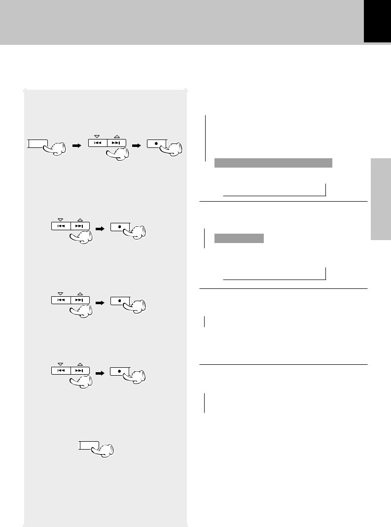
Setting up for surround sound 21
Setting speaker distances and system volume levels
Set the speaker distances and levels accurately for the best possible delivery of sound when listening to multichannel sources or when applying a digital soundfield to a stereo source.
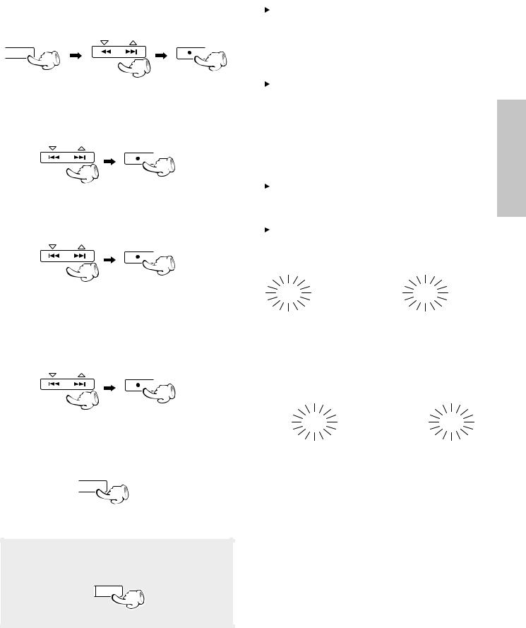
1 Select “Surround Options”.
MULTI CONTROL
MENU |
SET |
DEMO
2 Select “Speakers Distance”.
MULTI CONTROL
SET
3 Set the distance to the speakers.
MULTI CONTROL
SET
To decrease |
To increase |
the distance |
the distance |
Thefollowingitemscanbeselectedbypressingthe MULTI CONTROL keys repeatedly.
 (“CD Program Play”)
(“Recording Options”) “Tape Options” “Audio Options” “Clock Options”
 “Surround Options” (NV-701 only)
+“Surround Options” is scrolled in the display
Surround Opt
Thefollowingitemscanbeselectedbypressingthe MULTI CONTROL keys repeatedly.
 “Speakers Distance”
“Input Mode”
 “Speaker Selection”
+“Speakers Distance” is scrolled in the display
Speakers Dis
Use the MULTI CONTROL keys to set the distance and SET to proceed to the next setting. The speaker channels that the distance is being set for flash in the display.
Front speakers
Front “R” and “L” indicators flash
1ft 0.3m |
LS S RS |
|
L C R |
LFE SW
÷Set the distance to the center speaker and surround speakers in the same way.
÷The adustable range for all of the speakers is 1 to 30 ft. (0.3 to 10 m) in 1 ft. (0.3 m) steps.
÷When the distance settings are complete, set the volume levels.
section Preparation
Continued on next page...
22
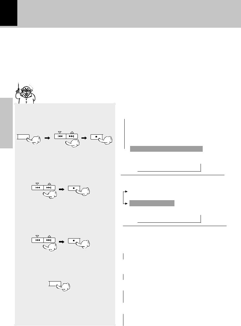
4 Turn on the test tone.
MULTI CONTROL
SET
|
5 Set the speaker levels. |
|
|
MULTI CONTROL |
|
|
||
section |
|
|
|
|
|
|
|
|
Preparation |
To decrease |
To increase |
|
||
|
the level |
the level |
|
6 Complete and save the settings. |
|
|
SET |
ENTER |
|
||
Setting up for surround sound
The test tone can be turned on and off by pressing the MULTI CONTROL keys repeatedly.
“Test ON”
“Test OFF”
÷The test tone is output from all of the speakers in the system in the following order:
3L (left front) 3C (center) 3R (right front)
SW(subwoofer)2LS(leftsurround)2RS(rightsurround)2
÷While listening to the test tone, use the MULTI CONTROL keys to adjust the volume levels of each channel when the channel name is displayed. The test tone continues to be output from the selected channel while adjustments are being made. If no adjustments are made for 2 seconds, the test tone resumes the cycle of speaker channels.
÷Adjust all of the speakers so that they sound the same from the listening position.
÷Because the subwoofer outputs extremely low frequencies, the volume may sound lower with respect to the other speakers.
Once you are through adjusting the levels of the speakers,presstheSETkeytoendthetesttoneand conclude adjustments.
+“Press ”ENTER” to save” is scrolled in the display
Press "ENTER
Press the ENTER key to save the settings.
Setting the audio for connected components (NV-701 only) 23
There are different types of audio connections available with this unit depending on what type of component you are making connections to. Select the type of audio input that best reflects the type of connections you have made to external components.
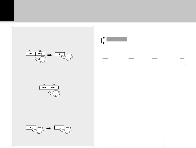
1 Select “Surround Options”.
MULTI CONTROL
MENU |
SET |
DEMO
2 Select “Input Mode”.
MULTI CONTROL
SET
3 Select the input.
MULTI CONTROL
SET
4 Set the input mode.
MULTI CONTROL
SET
5 Save the settings.
ENTER
Thefollowingitemscanbeselectedbypressingthe MULTI CONTROL keys repeatedly.
 (“CD Program Play”) (“Recording Options”) “Tape Options” “Audio Options” “Clock Options”
 “Surround Options” (NV-701 only)
+“Surround Options” is scrolled in the display
Surround Opt
Thefollowingitemscanbeselectedbypressingthe MULTI CONTROL keys repeatedly.
 “Speakers Distance”
“Input Mode”
 “Speaker Selection”
+“Input Mode” is scrolled in the display
Input Mode
The following items can be selected by pressing the MULTI CONTROL keys repeatedly.
 “VIDEO1”
  “VIDEO2”
÷The input setting is stored independently for each input. If you have made connections to components using both VIDEO 1 and VIDEO 2 input jacks, be sure to perform this procedure for each component.
The following items can be selected by pressing the MULTI CONTROL keys repeatedly.
 “D – Auto” (Automatic digital signal selection) “D – Manual” (Manual digital signal selection)
  “Analog”
÷Set “D – Auto” or “D – Manual“ when you have made connections to the DIGITAL VIDEO 1 COAX. IN jack or the DIGITAL VIDEO 2 OPT. IN jack.
÷When “D – Auto” is set, the format of the digital audio signal being input is automatically selected and decoded.
÷When “D – Manual” is set, the format of the digital audio signal being input is manually selected using the LSTN M. key on the remote control unit.
÷For more details on selecting a digital audio format, see “Surround play” on page 54.
÷Set “Analog” when you have made connections to the AUDIO – VIDEO 1 PLAY IN/REC OUT jacks or the AUDIO
– VIDEO 2/6 CH INPUT discreet input jacks (stereo/6- channel).
section Preparation
 Loading...