


KIV-BT900
KIV-700
DIGITAL MEDIA RECEIVER
Quick Start Guide
AUTORADIO NUMÉRIQUE
Guide de démarrage rapide
RECEPTOR DE MEDIOS DIGITALES
Guía de inicio rápido
© B59-2016-00/00 (KW)

Contents |
|
About the Quick Start Guide............... |
2 |
Before use .................................................. |
3 |
First step ..................................................... |
4 |
Basic Operations...................................... |
5 |
Playing Music (USB/iPod/Zune) ......... |
6 |
Listening to the Radio ........................... |
7 |
Hands-free phoning ............................... |
8 |
Basic Operations of Remote Control ... |
9 |
Accessories .............................................. |
10 |
Installation Procedure ......................... |
10 |
Before Installation................................. |
10 |
Connecting Wires to Terminals......... |
12 |
Installation/Removing the Unit........ |
14 |
Installation the Microphone Unit ... |
15 |
About the Quick Start
Guide
This Quick Start Guide explains the basic functions of this unit. For functions
not covered in this Guide, refer to the Instruction Manual (PDF file) contained in the included CD-ROM “Instruction Manual”. To refer to the Instruction Manual contained in the CD-ROM, a PC loaded with Microsoft® Windows XP/Vista/7 or Mac OS X® 10.4
or later is required in addition to Adobe® Reader™ 7.1 or Adobe® Acrobat® 7.1 or later. The Instruction Manual is subject to change for modification of specifications and so forth. You can download the latest version of the Instruction Manual from www.kenwood.com/cs/ce/.
2 | Quick Start Guide
Before use
2WARNING
To prevent injury or fire, take the following precautions:
•Do not watch or fix your eyes on the unit’s display when you are driving for any extended period.
•To prevent a short circuit, never put or leave any metallic objects (such as coins or metal tools) inside the unit.
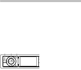
How to reset your unit
If this unit or the connected unit (auto disc changer, etc.) fails to operate properly, reset the unit. While pressing the [Volume] knob and the [MENU] button, press the
[SRC] button for at least 3 seconds. The unit returns to factory settings when the reset operation is complete.
SRC MENU Volume
Cleaning the Unit
If the faceplate of this unit is stained, wipe it with a dry soft cloth such as a silicon cloth. If the faceplate is stained badly, wipe the stain off with a cloth moistened with a neutral cleaner, then wipe it again with a clean soft dry cloth.
Applying spray cleaner directly to the unit may affect its mechanical parts. Wiping the faceplate with a hard cloth or using a volatile liquid such as thinner or alcohol
may scratch the surface or erase characters.
Notes
•If you experience problems during installation, consult your Kenwood dealer.
•When you purchase optional accessories, check with your Kenwood dealer to make sure that they work with your model and in your area.
•Characters that conform to ISO 8859-1 can be displayed.
•The RDS or RBDS feature won’t work where the service is not supported by any broadcasting station.
•The illustrations of the display and the panel appearing in this manual are examples used to explain more clearly how the controls are used. Therefore, what appears on the display in the illustrations may differ from what appears on the display on the actual equipment, and some of the illustrations on the display may be inapplicable.
English | 3
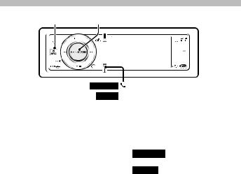
First step
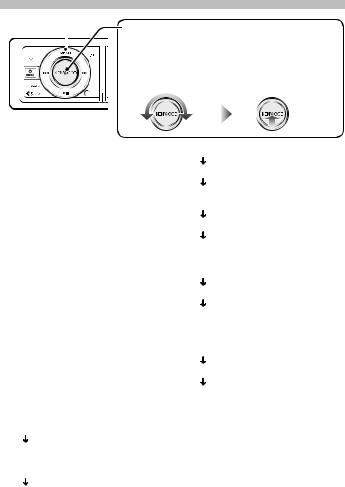
MENU |
Operation of the [Volume] knob |
||
|
|
When setting the unit, use the [Volume] knob to select |
|
|
|
the item and determine the setting. The operation of |
|
|
|
the knob is common for the most of the settings. |
|
|
|
1 Turn to select/ adjust |
2 Press to determine |
|
|
the item. |
the item/ setting. |
Exit Demonstration Mode
Turn off the demonstration mode when you use it for the first time after installation.
1Press the [Volume] knob to quit the demonstration mode when the message “To Cancel DEMO Press the volume knob” is displayed (approx. 15 seconds).
2Turn the [Volume] knob to select “YES”, and then press the [Volume] knob. The demonstration mode can also be canceled in the Menu List mode.
Refer to <Demonstration Mode Setting> (page 39) of Instruction manual.
Adjusting the Clock & Date
1Press the [MENU] button to enter the Menu List mode.
2Set the clock, time zone and date. Refer to <Operation of the [Volume] knob> for how to select the item and determine the setting.
3Setting the Clock
Select “Settings” “Clock & Date” “Time Synchronized”.
Select “ON” or “OFF”.
When selected “ON”, proceed to step 4. When selected “OFF”, continue.
Select “Clock Adjust”.
4| Quick Start Guide
Adjust hour, minute and time zone.
Press the [MENU] button to finish the clock adjustment.
Select “Summer Time”.
Select “ON” or “OFF”.
4Setting the Date
Select “Date Adjustment”. Adjust month, day and year.
Press the [MENU] button to finish the date adjustment.
5Date Format
Select “Date Mode”. Select Date format.
Press the [MENU] button for at least 1 second, and press it again briefly to exit the Menu List mode.
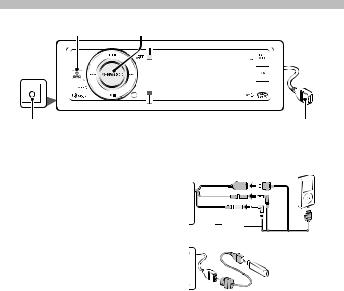
Basic Operations
SRC |
Volume |
AUX |
|
Auxiliary input |
USB Terminal |
Power
Turns the power ON by pressing the [SRC] button.
Press the [SRC] button for at least 1 second to turn the power OFF.
Source selection
Press the [SRC] button and then turn the [Volume] knob. To determine the selected source, press the [Volume] knob.
Tuner (“TUNER” or “HD RADIO”) j USB (“USB”), iPod (“iPod”) or Zune (“Zune”) j Internal Memory (“Int.Mem.”) j Auxiliary Input (“AUX”) j Standby (“STANDBY”) j Tuner...
Volume
Turn the [Volume] knob to adjust the sound volume.
USB terminal
iPod can be connected.
|
|
|
|
|
|
|
|
|
|
|
|
|
|
|
|
|
|
|
|
|
|
|
|
AUDIO |
iPod |
|
|
|
|
|
|
|
|
|
|
|
|
|
|
|
|
|
|
|
|||
IN |
|
|
VIDEO |
iPod |
|
|
|
|
|
|
|
|
|
|
|
|
|
|
|
iPod |
|||
|
|
|
IN |
|
|
|
|
|
|
|
AUDIO OUT |
|
|
|
|
|
|
|
|
|
|
|
|
|
|
|
|
|
|
|
|
iPod |
|||
|
|
|
|
|
|
|
|
|
VIDEO OUT |
|
|
USB device can be connected.
When connecting the USB device, usage of the CA-U1EX (option) is recommended.
Auxiliary input
Portable audio device can be connected with the stereo mini-plug (3.5 mm ø). Auxiliary input source is initially set to “OFF”. Set “Built in AUX” described in <Initial Settings> (page 38) (Instruction manual) to “ON”.
English | 5

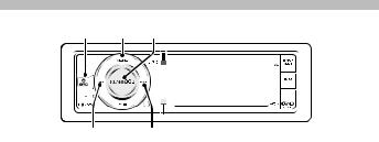
Playing Music (USB/iPod/Zune)
MENU Volume DISP SEARCH MODE
4 38 ¢ KIV-BT900
KIV-700 PLAY MODE
Playing USB device
Connect a USB device, iPod or Zune to the USB terminal.
When connected, the source is switched automatically and a song starts playing.
Moving to the next folder on USB
Press the [SEARCH MODE] button.
Selecting a Song
Press the [4] or [¢] button to select a song.
This unit cannot be operated for a few seconds while reading Artwork after selecting a song.
Fast Forward or Fast Backward of the Song
Press and hold the [4] or [¢] button to fast-forward or fast-backward the audio file containing songs.
Pause and play
Press the [38] button to pause or resume playing a song.
Removing USB device, iPod or Zune
Press the [38] button for at least 2 seconds to enter the USB Remove mode (“USB REMOVE” is displayed) and the USB device can be removed safely.
Switching display
Press the [DISP] button to select display mode.
Selects the Artwork small, Artwork large, Video or Clock.
Music Search
1Press the [MENU] button.
2Turn the [Volume] knob and press it when the desired item is displayed. USB: Select “USB List” or “Music”. iPod: Select “Music” or “Videos”. Zune: Select “Music”.
3Search for music.
Operation type |
Operation |
|
Move between items |
Turn the [Volume] knob. |
|
Select an item |
Press the [Volume] knob. |
|
Page up or down |
Press the [DISP] or [ |
] / |
|
[PLAY MODE] button. |
|
|
Press the [DISP] or [ |
] / |
|
[PLAY MODE] button for at |
|
|
least 1 second to continuously |
|
|
scroll. Press the button again to |
|
|
stop scrolling. |
|
Return to previous item |
Press the [MENU] button. |
|
Return to Top menu |
Press the [MENU] button for at |
|
|
least 1 second. |
|
To cancel the music search operation of Audio file or iPod, press the [MENU] button for at least 1 second, and then press it again briefly.
6 | Quick Start Guide
Listening to the Radio
SRC MENU Volume
4 ¢
Selecting a Tuner source
1Press the [SRC] button.
2Turn the [Volume] knob to select “TUNER”, and then press the [Volume] knob.
Selecting the Band
1Press the [MENU] button.
2Turn the [Volume] knob to select desired band (“FM1”, “FM2”, “FM3”, or “AM”), and then press the [Volume] knob.
Selecting a Station
Press the [4] or [¢] button to select the station you want to listen to.
Station Preset Memory
1Press the [4] or [¢] button to select the station you want to memory.
2Press the [MENU] button.
3Turn the [Volume] knob to select “List & Memory”, and then press the [Volume] knob.
4Turn the [Volume] knob to select preset number (“1” – “6”), and then press the [Volume] knob for at least 2 seconds.
Recalling the stations in the memory
1Press the [MENU] button.
2Turn the [Volume] knob to select “List & Memory”, and then press the [Volume] knob.
3Turn the [Volume] knob to select recall number (“1” – “6”), and then press the
[Volume] knob.
English | 7
Function of KIV-BT900, KIV-700 with KCA-BT300/KCA-BT200 (Optional Accessory)
Hands-free phoning
SRC Volume
KIV-BT900
KIV-700 PLAY MODE
Registering your cellphone in this unit
1By operating the cellphone, register the hands-free unit (pairing). Select “KENWOOD BT USB/R-3P1”, “KCA-BT300”
or “KCA-BT200” from the list of connected units.
2Enter the PIN code of this unit from the cellphone.
The PIN code of this unit is “0000” by default.
When registration of your cellphone is complete, the phone book of the
cellphone is automatically downloaded to this unit. (If the phone book has not been downloaded to this unit, operate the cellphone to download it.)
Calling a number in the Phone Book
If the phone book has not been downloaded to this unit, operate the cellphone to download it.
1 KIV-BT900
Press the [ ] button.
KIV-700
Press the [PLAY MODE] button for at least 1 second.
2Turn the [Volume] knob to select “Phonebook”, and then press the
[Volume] knob.
3Turn the [Volume] knob to select initial of name, and then press the [Volume] knob.
4Turn the [Volume] knob to select phone number.
5Press the [Volume] knob to dial.
Answering a Phone Call
Press the [Volume] knob.
Disconnecting a Call
Press the [SRC] button.
8 | Quick Start Guide
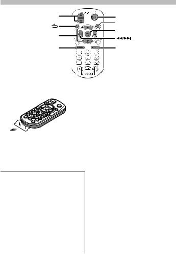
Basic Operations of Remote Control
VOL |
SRC |
|
ATT |
5/∞ |
38 |
|
|
AM– |
FM+ |
Preparing the remote control unit
Pull the battery sheet out from the remote control unit to the direction of the arrow.
¤CAUTION
•Keep battery out of reach of children and in original package until ready to use. Dispose of used batteries promptly. If swallowed contact physician immediately.
•Do not leave the battery near fire or under direct sunlight. A fire, explosion or excessive heat generation may result.
•Do not set the remote control in hot places such as on the dashboard.
•Danger of explosion if Lithium battery is incorrectly replaced. Replace only with the same or equivalent type.
General control
•Volume control: [VOL]
•Source select: [SRC]
•Volume reduce: [ATT]
When the button is pressed again, the volume returns to the previous level.
In Tuner/HD Radio source
•Band select: [FM+]/[AM–]
•Station select: [4]/[¢]
•Recall preset stations: [1] — [6]
In USB/ Internal Memory source
•Music select: [4]/[¢]
•Folder select: [FM+]/[AM–]
•Pause/Play: [38]
•Movement between Menulist mode:
[5]/[∞]
•Return to previous folder: [ ]
]
In iPod source
•Movement between Menulist mode:
[5]/[∞]
•Return to previous item: [ ]
]
•Music select: [4]/[¢]
•Pause/Play: [38]
English | 9
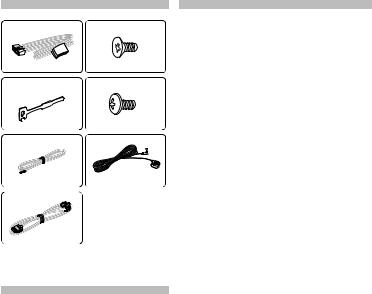
Accessories |
Before Installation |
1 |
5 |
........1 |
........4 |
2 |
6 |
........2 |
........4 |
3 |
7* |
....1 (2 m) |
....1 (3 m) |
4 |
* KIV-BT900 only |
|
|
....1 (2.5 m) |
|
Installation Procedure
1.To prevent a short circuit, remove the key from the ignition and disconnect the - battery.
2.Make the proper input and output wire connections for each unit.
3.Connect the speaker wires of the wiring harness.
4.Connect the wiring harness wires in the following order: ground, battery, ignition.
5.Connect the wiring harness connector to the unit.
6.Install the unit in your car.
7.Reconnect the - battery.
8.While pressing the [Volume] knob and the [MENU] button, press the [SRC] button for at least 3 seconds.
10 | Quick Start Guide
2WARNING
If you connect the ignition wire (red) and the battery wire (yellow) to the car chassis (ground), you may cause a short circuit, that in turn may start a fire. Always connect those wires to the power source running through the fuse box.
¤
•Mounting and wiring this product requires skills and experience. For safety’s sake, leave the mounting and wiring work to professionals.
•Make sure to ground the unit to a negative 12V DC power supply.
•Do not install the unit in a spot exposed to direct sunlight or excessive heat or humidity. Also avoid places with too much dust or the possibility of water splashing.
•Do not use your own screws. Use only the screws provided. If you use the wrong screws, you could damage the unit.
•If the power is not turned ON (“Protect” is displayed), the speaker wire may have a short-circuit or touched the chassis of the vehicle and the protection function may have been activated. Therefore, the speaker wire should be checked.
•If your car’s ignition does not have an ACC position, connect the ignition wires to a power source that can be turned on and off with the ignition key. If you connect the ignition wire to a power source with a constant voltage supply, as with battery wires, the battery may die.
•If the fuse blows, first make sure the wires aren’t touching to cause a short circuit, then replace the old fuse with one with the same rating.
•Insulate unconnected wires with vinyl tape or other similar material. To prevent a short circuit, do not remove the caps on the ends of the unconnected wires or the terminals.
•Connect the speaker wires correctly to the terminals to which they correspond. The unit may be damaged or fail to work if you share the - wires or ground them to any metal part in the car.
•When only two speakers are being connected to the system, connect the connectors either to both the front output terminals or to both the rear output terminals (do not mix front and rear). For example, if you connect the + connector of the left speaker to a front output terminal, do not connect the - connector to a rear output terminal.
•After the unit is installed, check whether the brake lamps, blinkers, wipers, etc. on the car are working properly.
•Reception may drop if there are metal objects near the Bluetooth antenna.
Bluetooth antenna unit
About CD players/disc changers connected to this unit
If the CD player/ disc changer has the “O-N” switch, set it to the “N” position.
The functions you can use and the information that can be displayed may differ depending on the models being connected.
For Good Reception
To assure good reception, note the following:
•Communicate with the cell-phone within the line-of-sight distance of 10 m (30
ft). The communication range becomes shorter depending on the surrounding environment. The communication range also becomes shorter when there is an obstacle between this unit and the cell-phone. The above maximum communication range (10 m) is not always assured.
•A broadcast station or walkie-talkie located nearby can interfere with communication due to too strong signal.
¤CAUTION
Install this unit in the console of your vehicle.
Do not touch the metal part of this unit during and shortly after the use of the unit. Metal part such as the heat sink and enclosure become hot.
English | 11

Connecting Wires to Terminals
Parking sensor wire Junction cable |
Parking sensor wire (Light Green) |
(Light Green) (Accessory 3) |
For the sake of safety, be sure to connect the parking sensor.
⁄ Connect to the vehicle’s parking brake detection switch harness.
USB device (commercially available)
iPod (commercially available)
iPod cable (Accessory 4)
⁄Do not remove the cap when you do not use the USB cable. The connector will cause the unit to malfunction if it gets in touch with any metallic part of the vehicle.
USB connector (1m)
iPod |
IN |
iPod VIDEOIN |
AUDIO |
||
iPod |
|
|
AUDIO OUT |
|
|
iPod |
|
|
VIDEO OUT |
|
|
iPod audio output |
|
(Left: White, Right: Red) |
|
Microphone input |
iPod AUDIO OUT iPod OUTVIDEO |
(KIV-BT900 only) |
|
(Yellow) |
|
|
|
Microphone |
iPod visual output |
|
|
||
|
|
|
|
|
|
(Accessory7) |
|
|
|
||
|
|
||
|
|
(KIV-BT900 only) |
|
⁄
•Speaker Impedance
:4 – 8 Ω
•USB terminal Maximum Supply current
:500 mA
Ignition key switch
Car fuse box (Main fuse)
|
|
White |
To front left speaker |
White/Black |
|
|
|
Gray |
To front right speaker |
Gray/Black |
|
|
|
Green |
To rear left speaker |
Green/Black |
|
|
|
Purple |
To rear right speaker |
Purple/Black |
|
Car fuse |
|
|
box |
|
|
ACC |
Ignition wire (Red) |
|
|
Battery wire (Yellow) |
|
Ground wire (Black) · (To car chassis)
+
–
Battery
12 | Quick Start Guide

PRK SW
|
|
|
Rear output |
|
|
R |
L Front output |
|
|
|
Sub Woofer output |
Fuse (10A) |
|
|
Antenna Cord |
|
|
FM/AM antenna input (JASO) |
|
R |
L |
AUX input (Stereo) |
|
|
|
Use the mini-plug (3.5 mm ø) which is stereo |
|
|
|
type and does not have any resistance. |
|
|
|
To Kenwood disc changer/ External optional |
|
Wiring harness |
|
accessory |
|
|
⁄ To connect these leads, refer to the |
||
(Accessory 1) |
|
||
|
|
relevant instruction manuals. |
|
If no connections are made, do not let the wire come out from the tab.
Power control wire (Blue/White)
P.CONT
Motor antenna control wire (Blue)
ANT.
CONT
Mute control wire (Brown)
MUTE
Dimmer control wire (Orange / White)
ILLUMI
Steering remote control wire (Light Blue/Yellow)
REMOTE CONT
STEERING WHEEL
REMOTEINPUT
When using the optional power amplifier, connect to its power control terminal.
Depending on what antenna you are using, connect either to the control terminal of the motor antenna, or to the power terminal for the booster amplifier of the film-type or short pole type antenna.
To connect the Kenwood navigation system, consult your navigation manual.
⁄Connect to the terminal that is grounded when either the telephone rings or during conversation. (KIV-700 only)
To car light control switch
To use the steering wheel remote control feature, an exclusive remote adapter (not supplied) that matches your car is required.
English | 13
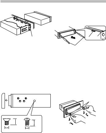
Installation/Removing the Unit
Non-Japanese cars
Bend the tabs of the mounting sleeve with a screwdriver or similar utensil and attach it in place.
⁄
•Make sure that the unit is installed securely in place. If the unit is unstable, it may malfunction (for example, the sound may skip).
Japanese cars
1.Refer to the section <Removing the hard rubber frame> and then remove the hard rubber frame.
2.Align the holes in the unit (two locations on each side) with the vehicle mounting bracket and secure the unit with the accessory screws.
T N
 T/N
T/N
N T
T: Toyota cars
N: Nissan cars
5 |
|
6 |
|
8 mm |
8mm |
|
MAX. |
|
|
MAX. |
|
|
|
|
ø5mm |
|
ø5mm |
Accessory5...for Nissan car
Accessory6...for Toyota car
Removing the hard rubber frame
1.Engage the catch pins on the removal tool and remove the two locks on the upper level.
Lift up and pull the frame forward as shown in the figure.
Lock Catch 
Removal tool (Accessory2)
2.When the upper level is removed, remove the lower two locations.
⁄
•The frame can be removed from the bottom side in the same manner.
Removing the Unit
1.Refer to the section <Removing the hard rubber frame> and then remove the hard rubber frame.
2.Insert the two removal tools deeply into the slots on each side, as shown.
3.Lower the removal tool toward the bottom, and pull out the unit halfway while pressing towards the inside.
Accessory 2
¤
•Be careful to avoid injury from the catch pins on the removal tool.
4.Pull the unit all the way out with your hands, being careful not to drop it.
14 | Quick Start Guide
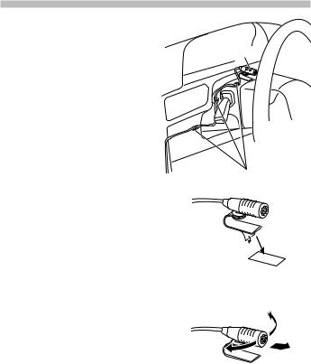
KIV-BT900 only
Installation the Microphone Unit
1.Check the installation position of the microphone (accessory 7).
2.Remove oil and other dirt from the
|
installation surface. |
Accessory7 |
3. |
Install the microphone. |
|
4. |
Wire the cable up to the unit with it |
|
|
secured at several positions using tape or |
|
|
the like. |
|
⁄
• Install the microphone as far as possible from the cell-phone.
Fix a cable with a commercial item of tape.
Peel the release coated paper of doubleface adhesive tape to fix on the place shown above.
Adjust the direction of the microphone to the driver.
English | 15
 Loading...