


MICRO HI-FI COMPONENT SYSTEM
HM-331
INSTRUCTION MANUAL
KENWOOD CORPORATION
COMPACT
DIGITAL AUDIO
TEXT
B60-4228-00 00 CH (M,T) OC 9809
2 |
Before applying power |
Caution : Read this page carefully to ensure safe operation. |
|
|
|
|
|
HM-331 (En/T) |
Units are designed for operation as follows.
Europe and U.K. .................................................. |
AC 230V only |
*Other countries ........... |
AC 110-120 / 220-240 V switchable |
Preparation section
For the United Kingdom
Factory fitted moulded mains plug
1.The mains plug contains a fuse. For replacement, use only a 3-Amp ASTA-approved (BS 1362) fuse.
2.The fuse cover must be refitted when replacing the fuse in the moulded plug.
3.Do not cut off the mains plug from this equipment. If the plug fitted is not suitable for the power points in your home or the cable is too short to reach.
A power point, then obtain an appropriate safety approved extension lead or adapter, or consult your dealer. If nonetheless the mains plug is cut off, remove the fuse and dispose of the plug immediately, to avoid a possible shock hazard by inadvertent.
Connection to the mains supply.
IMPORTANT :
The wires in the mains lead are coloured in accordance with the following code: Blue : Neutral
Brown : Live
Do not connect those leads to the earth terminal of a three-pin plug.
*For other countries
AC voltage selection
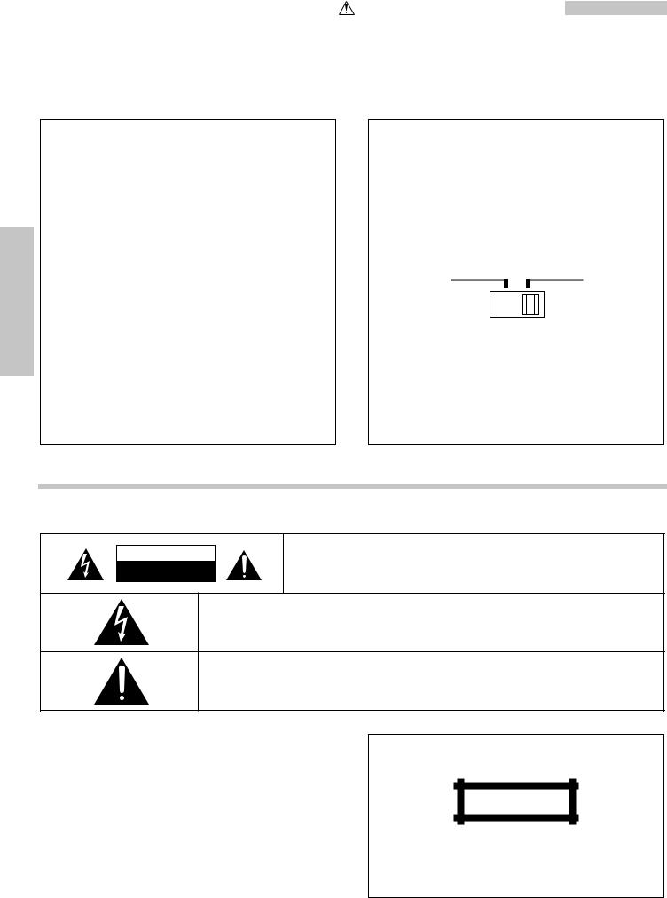
The AC voltage selector switch on the rear panel is set to the voltage that prevails in the area to which the unit is shipped. Before connecting the power cord to your AC outlet, make sure that the setting position of this switch matches your line voltage. If not, it must be set to your voltage in accordance with the following direction.
AC voltage selector switch
AC 110–120V AC 220–240V
Move switch lever to match your line voltage with a small screwdriver or other pointed tool.
Note:
Our warranty does not cover damage caused by excessive line voltage due to improper setting of the AC voltage selector switch.
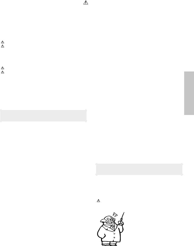
Safety precautions
WARNING : TO PREVENT FIRE OR ELECTRIC SHOCK, DO NOT EXPOSE THIS APPLIANCE TO RAIN OR MOISTURE.
CAUTION
RISK OF ELECTRIC SHOCK
DO NOT OPEN
CAUTION: TO REDUCE THE RISK OF ELECTRIC SHOCK, DO NOT REMOVE COVER (OR BACK). NO USER-SERVICEABLE PARTS INSIDE, REFER SERVICING TO QUALIFIED SERVICE PERSONNEL.
THE LIGHTNING FLASH WITH ARROWHEAD SYMBOL, WITHIN AN EQUILATERAL TRIANGLE, IS INTENDED TO ALERT THE USER TO THE PRESENCE OF UNINSULATED “DANGEROUS VOLTAGE” WITHIN THE PRODUCT’S ENCLOSURE THAT MAY BE OF SUFFICIENT MAGNITUDE TO CONSTITUTE A RISK OF ELECTRIC SHOCK TO PERSONS.
THE EXCLAMATION POINT WITHIN AN EQUILATERAL TRIANGLE IS INTENDED TO ALERT THE USER TO THE PRESENCE OF IMPORTANT OPERATING AND MAINTENANCE (SERVICING) INSTRUCTIONS IN THE LITERATURE ACCOMPANYING THE APPLIANCE.
The marking of products using lasers (Except for some areas)
CLASS 1
LASER PRODUCT
The marking is located on the rear panel and says that the component uses laser beams that have been classified as Class 1. It means that the unit is utilizing laser beams that are of a weaker class. There is no danger of hazardous radiation outside the unit.
|
|
Caution : Read this page carefully to ensure safe operation. |
3 |
||
|
|
|
Before applying power |
||
|
|
|
|
|
|
|
|
|
HM-331 (En/T) |
||
|
Contents |
|
|
|
|
|
Preparation section |
|
Application section |
|
|
|
|
|
|
|
|
Before applying power ............................... |
2 |
Safety precautions ........................................................... |
2 |
Special features ................................................................ |
4 |
Handling of discs .............................................................. |
5 |
Notes on cassette tape .................................................... |
5 |
System connection........................................... |
6 |
Connection of the System Accessories ....................... |
6 |
Connection of Other Accessories |
|
(Commercially Available Parts) ............................... |
8 |
Controls and indicators ................................... |
9 |
Display ................................................................................ |
9 |
Main unit ........................................................................... |
10 |
Remote control Unit ......................................................... |
12 |
Operation of remote control unit ................. |
13 |
CHANNEL SPACE setting ................................................ |
13 |
Basic section |
|
Let's put out some sound............................... |
14 |
Basic use method............................................................ |
14 |
Playback of CD ................................................................ |
16 |
In regard to CD-TEXT ...................................................... |
17 |
Playback of tape.............................................................. |
18 |
Receiving broadcast station .......................................... |
20 |
Let's recording ................................................ |
22 |
Recording on TAPE .......................................................... |
22 |
Playback of CD................................................ |
24 |
Listening in the desired sequence |
|
(program playback) ................................................... |
24 |
Repeated playback .......................................................... |
25 |
Listening to an unexpected title sequence |
|
(random playback) ..................................................... |
26 |
R.D.S. (Radio Data System) |
|
(Except for some areas) ........................................................ |
28 |
Searching for a desired program type |
|
(PTY search) ............................................................... |
29 |
To be able to listen to the desired information |
|
at any time ................................................................... |
31 |
Convenient Recording Methods .................. |
33 |
Selection of the Recording type .................................... |
33 |
One-touch recording (CD=TAPE) ................................ |
34 |
Program recording (CD =TAPE) .................................. |
35 |
Tone adjustment ............................................. |
36 |
Tone adjustment .............................................................. |
36 |
Balance adjustment........................................................ |
36 |
Adjusting the AUX Input Level ....................................... |
37 |
Clock adjustment............................................ |
38 |
Timer operation................................................ |
39 |
Setting the O.T.T. ............................................................... |
39 |
Setting the Program Timer ............................................ |
40 |
Activating or deactivating the O.T.T. or |
|
program timer execution ......................................... |
42 |
Sleep timer ....................................................................... |
42 |
section Preparation
Knowledge section |
|
Important Items ............................................... |
43 |
Maintenance ..................................................................... |
43 |
Reference .......................................................................... |
43 |
In case of difficulty ........................................ |
44 |
Specifications ............................................ |
47 |
4
Special features
Before applying power
HM-331 (En/T)
CD player and auto-reverse cassette deck as standard equipment
A CD player and auto-reverse cassette deck are provided, making the unit an integrated micro stereo system for enjoyment of multiple music sources.
Convenient Recording Methods
Various versatile recording functions are provided according to the use purposes.
÷One-touch recording |
: Recording of one CD or one track by pressing a single key |
÷Program recording |
: Any desired tracks can be recorded in the desired sequence |
Preparation section
Convenient timer functions
Two-program timer : Timer playback, timer recording and AI timer playback can be programmed.
AI timer |
: When the unit is turned ON by the timer, the sound level increases gradually. |
O.T.T. |
: Timer with easy setting, which operates only once. |
Sleep timer |
: Useful when you want to go asleep while listening to music. |
In regard to demonstration |
set/demo |
|
This unit is equipped with a demonstration function |
|
|
(only display). The demonstration consists of sequen- |
DEMO OFF (To cancel demonstration): |
|
tial change of display and indicators showing the |
||
Press the “set/demo” key when DEMO is ON. |
||
operations, but the audio itself does not change. The |
||
DEMO ON (To execute demonstration): |
||
demonstration function can be cancelled as follows. |
||
After turning power ON, press and hold the |
||
|
||
|
“set/demo” key (for more than 2 seconds). |
÷Even when DEMO is ON, stations with weak radio waves are muted and their sound cannot be heard.
÷This operates automatically when a power failure has occurred or the plug of the power cable has been pulled while the power was ON. Cancellation is possible by pressing the key during the demonstration.
Unpacking
Unpack the unit carefully and make sure that all accessories are put aside so they will not be lost.
Examine the unit for any possibility of shipping damage. If your unit is damaged or fails to operate, notify your dealer immediately. If your unit was shipped to you directly, notify the shipping company without delay. Only the consignee (the person or company receiving the unit) can file a claim against the carrier for shipping damage.
We recommend that you retain the original carton and packing materials for use should you transport or ship the unit in the future.
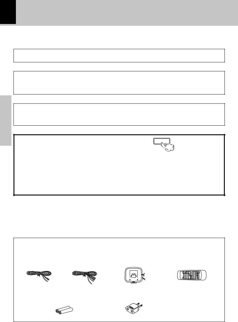
Accessories |
Please confirm that the following accessories are present. |
|
|||||||||
FM indoor antenna (1) |
Loop antenna (1) |
Remote control unit (1) |
|||||||||
Europe, and U.K. |
Other countries |
|
|
|
|
|
|
|
|
|
|
|
|
|
|
|
|
|
|
|
|
|
|
|
|
|
|
|
|
|
|
|
|
|
|
|
|
|
|
|
|
|
|
|
|
|
|
|
|
|
|
|
|
|
|
|
|
|
|
|
|
|
|
|
|
|
|
|
|
|
|
|
|
|
|
|
|
|
|
|
|
|
|
|
|
|
|
|
|
|
|
|
|
|
|
|
|
|
|
|
|
|
|
|
|
|
|
|
|
|
|
|
|
|
|
|
|
|
|
Batteries (R6/AA) (2) |
*AC plug adaptor (1) |
*Use to adapt the plug on the power cord to the shape of the wall outlet. (Accessory only for regions where use is necessary.)
Before applying power 5
HM-331 (En/T)
Handling of discs
Disc handling precautions
|
Handling |
|
Hold the discs so that you do not |
|
touch the playing surface. |
|
Label side |
|
Playing side |
Sticker |
Do not attach paper or tape to ei- |
|
ther the playing side or the label side |
|
of the discs. |
Sticky paste
Cleaning
If fingerprints or foreign matter become attached to the disc, lightly wipe the disc with a soft cotton cloth (or similar) from the center of the disc outwards in a radial manner.
Storage
When a disc is not to be played for a long period of time, remove it from the player and store it in its case.
Discs which can be played with this unit
CD (12 cm, 8 cm), and the audio part of CDV, CD-G, CD-EG and CD-EXTRA.
Use discs that comply with the IEC standard, for example
a disc carrying the |
COMPACT marking on the label surface. |
|
DIGITAL AUDIO |
Never play a cracked or warped disc
During playback, the disc rotates at high speed in the player. Therefore, to avoid danger, never use a cracked or deformed disc or a disc repaired with tape or adhesive agent.
Please do not use discs which are not round because they may cause a malfunction.
Disc accessories
The disc accessories (stabilizer, protection sheet, protection ring, etc.) which are marketed for improving the sound quality or protecting discs as well as the disc cleaner should not be used with this system because they may cause malfunction.
section Preparation
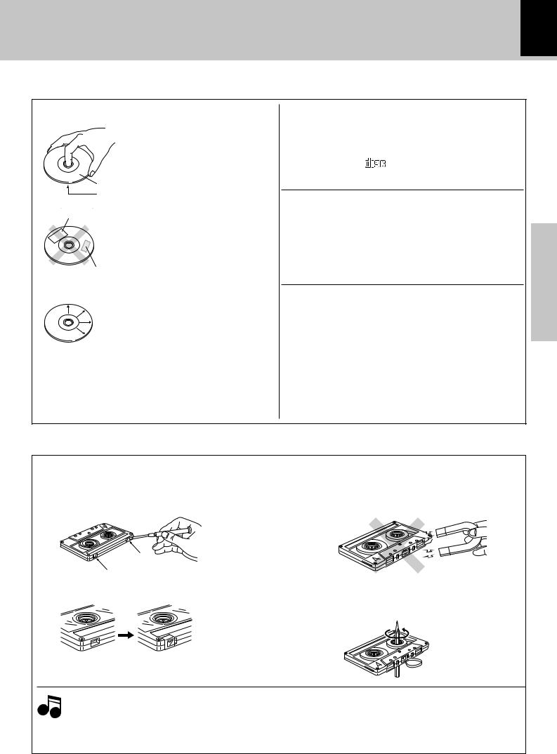
Notes on cassette tape
Safety tab (accidental erasure prevention tab)
After an important recording has been finished, break the safety tab, to prevent the recorded contents from being erased or recorded on accidentally.
To store cassette tapes
Do not store the tapes in a place which is subject to direct sunlight, or near equipment that generates heat. Keep the cassette tapes away from any magnetic field.
|
N |
|
S |
For A side |
|
For B side |
When there is slack in the tape |
|
|
|
In such a case, insert a pencil into the reel hole and wind |
|
the reel hub to remove the slack. |
To re-record Apply tape only to the position where the tab has been removed.
1.Longer tape than 110 minutes cassette tape
Notes Since longer tape than 110 minutes cassette tape is very thin, the tape could adhere to the pinch roller or be easily broken. It is recommended that these tapes not be used with this unit to prevent possible damage.
2.Endless tapes
Do not use an endless tape, as this could damage the mechanism of the unit.
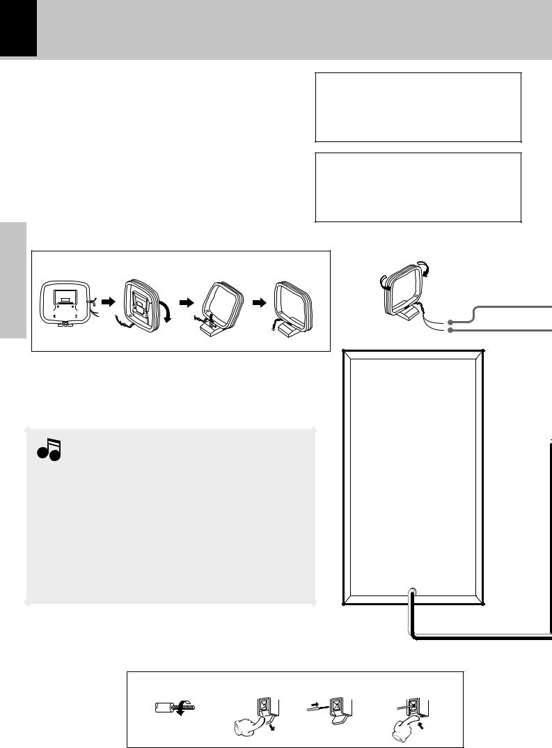
6 System connection
Connection of the System Accessories
This figure shows the method of connection between the main unit and provided accessories.
HM-331 (En/T)
CAUTION Note on Connection
Connect the components as shown in the diagram.
Only plug the power cord into a power outlet once connections are completed.
Preparation section
AM loop antenna
The supplied antenna is for indoor use. Place it as far as possible from the main system, TV set, speaker cords and power cord, and set it to a direction which provides the best reception.
1 |
|
|
2 |
3 |
4 |
||||
|
|
|
|
|
|
|
|
|
|
|
|
|
|
|
|
|
|
|
|
|
|
|
|
|
|
|
|
|
|
|
|
|
|
|
|
|
|
|
|
|
|
|
|
|
|
|
|
|
|
|
|
|
|
|
|
|
|
|
|
|
|
|
|
|
|
|
|
|
|
|
|
|
|
|
|
|
|
|
|
Malfunction of microcomputer
If operation is not possible or erroneous display appears even though all connections have been made properly, reset the microcomputer referring to “In case of difficulty”. ®r
|
|
|
Speaker (right) |
Notes |
|
|
|
1.Never short-circuit the “+” and “-” speaker cords. |
|
|
|
2.If the left and right speaker connections or the “+” and “-” polarity |
|
||
are inverted, the sound will be unnatural with unclear positioning of |
|
||
musical instruments, etc. Be sure to connect them without mistake. |
|
||
3.Be sure to insert all connection cords securely. If their connections |
|
||
are imperfect, the sound may not |
be produced or noise may |
|
|
interfere. |
|
|
|
4.Before plugging or unplugging a connection cord, be sure to unplug |
|
||
the power cord from the wall AC outlet. If connection cords are |
|
||
plugged or unplugged with the power cord left plugged in, malfunction |
|
||
or damage may result. |
|
|
|
Main Unit |
|
|
|
1 |
2 |
3 |
4 |
Twist

System connection 7
HM-331 (En/T)
FM indoor antenna
The accessory antenna is for temporary indoor use only.For stable signal reception we recommend using an outdoor antenna. Remove the indoor antenna if you connect one outdoors.
Europe, and U.K.
FM 75Ω
AM
GND
1Remove the insulation from the end of the cord end.
(Except for Europe, and U.K.) 2Connect it to the antenna terminal.
3Locate the position providing good reception condition.
4Fix the antenna.
Other countries
FM 300Ω
FM 75Ω
AM
GND
section Preparation
|
|
SPEAKERS |
|
ANTENNA |
|
(6–16Ω) |
|
|
SPEAKERS |
|
|
|
(6–16Ω ) |
|
|
|
|
+ |
|
FM |
+ |
L |
|
300Ω |
|||
FM |
L |
– |
|
– |
|||
75Ω |
|
||
AM |
– |
– |
|
GND |
R |
|
|
|
R |
||
|
+ |
||
|
|
||
|
|
+ |
DIGITAL |
|
OUT |
SUPER |
OPTICAL |
WOOFER |
|
PRE OUT |
MANUAL 


 AUTO
AUTO
PANEL
OPEN/CLOSE
AUX INPUT
R L
POWER cord
TO WALL AC
OUTLET
AC 110–120V AC 220–240V
Speaker cord
Connect correctly + to + and - to -.
Speaker (left) |
PANEL OPEN/CLOSE switch |
|
|
|
Change the operation mode of the "REVOLVING |
2 |
2 |
|
CONTROL PANEL". |
! |
|
|
8 |
System connection |
|
|
|
|
|
HM-331 (En/T) |
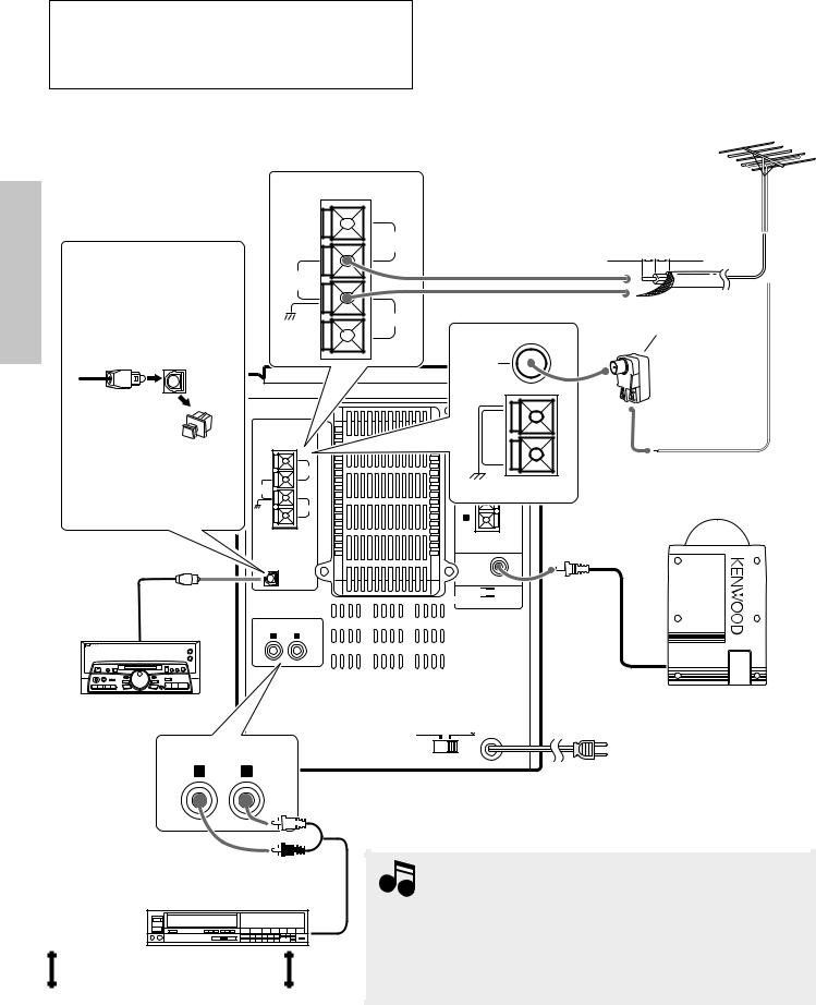
Connection of Other Accessories (Commercially Available Parts)
CAUTION Note on Connection
Connect the components as shown in the diagram. Only plug the power cord into a power outlet once connections are completed.
Preparation section
FM outdoor antenna
Other countries
|
FM |
DIGITAL OUT jack |
300Ω |
|
|
(OPTICAL) |
FM |
75Ω |
|
|
AM |
DIGITAL |
GND |
OUT |
|
OPTICAL |
|
Lead the 75Ω coaxial cable connected to the FM outdoor antenna into the room and connect it to the FM 75Ω terminal. Please remove the indoor antenna after an outdoor antenna has been installed.
10mm 10mm
Antenna adaptor (optional)
FM 75Ω
Optical-fiber |
|
|
cable |
ANTENNA |
|
Cap |
|
|
|
|
FM |
If necessary, remove the |
|
300Ω |
FM |
|
|
cap and plug the optical- |
|
|
75Ω |
|
|
|
|
|
fiber cable (optional) |
GND |
AM |
|
||
Optical-fiber cable |
DIGITAL |
|
OUT |
|
|
OPTICAL |
|
|
|
AUX INPUT |
|
|
R |
L |
MD recorder or
DAT etc.
AUX INPUT
R L
Audio cord
Audio output
VCR, Analog turntable with built-in
RIAA equalizer (optional P-110), etc.
SPEAKERS(6–16Ω ) AM |
|
+ |
|
L |
GND |
– |
|
– |
|
R |
|
+ |
|
SUPER
WOOFER
PRE OUT
MANUAL 


 AUTO
AUTO
PANEL
OPEN/CLOSE
AC 110–120V AC 220–240V
Europe, and U.K.
SUPER WOOFER
POWER cord
TO WALL AC OUTLET
Notes
1.In case an associated system component is connected, also read the instruction manual of the component.
2.Insert the optical-fiber cable straight into the connector until it clicks. 3.Be sure to attach the protection cap when the connector is not used. 4.Never band or bundle the optical-fiber cable.
Controls and indicators
9
HM-331 (En/T)
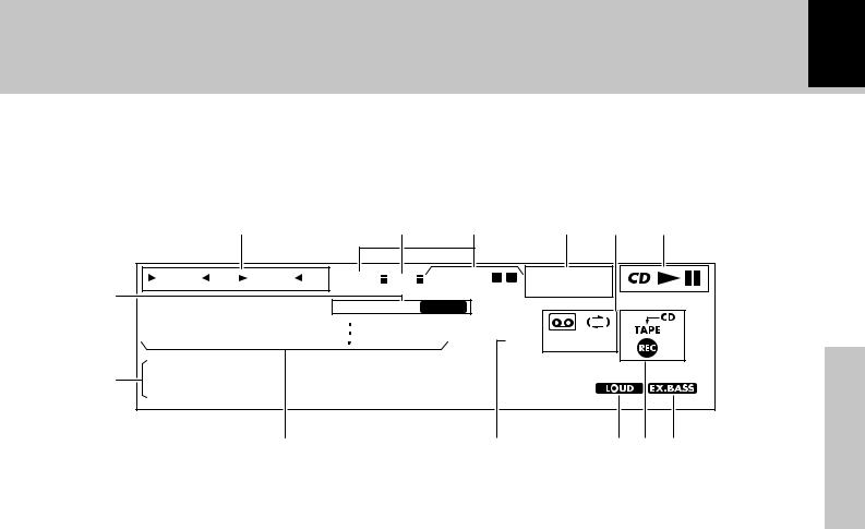
Display
(The displays given in this manual are approximations only. They may differ from what actually appears on the display.)
|
|
8 |
9 |
0 |
|
! @ |
# |
|
|
RANDOM PGM REPEAT |
ALL SLEEP A.P.S. O.T.T. PROG. 1 |
2 |
R·D·S EON NEWS |
|
|
||
1 |
|
|
|
|
|
TP TA PTY |
|
|
|
TRACK NO. |
TOTAL AUTO TUNED |
STEREO |
|
|
|
|
|
|
FM |
|
|
|
|
|||
|
8 8 8 8 8 8 8 8 |
|
|
|
|
|
||
|
AM |
kHz |
O.T.E. NR T.E. |
|
|
|||
|
PM |
MHz |
|
|
||||
|
|
|
|
|
|
TITLE SEARCH |
|
|
2 |
• • • • • • •MD•EDIT • • • |
Preparation |
||||||
|
|
3 |
|
4 |
|
5 6 7 |
||
|
|
|
|
section |
||||
|
|
|
|
|
|
|
|
|
1 Tuner-related indicators
2 Character information display section (dot display)
Shows character information including the input selection, volume level and disc/track title.
3Character information display section
Frequency indication, time indication, track No., program No.,
etc.
4 O.T.E. (ONE TOUCH EDIT) indication
Appears during one-touch recording.
5 LOUD (Loudness) indication
6 TAPE REC indicators
7 EX.BASS (extra bass) indication
8 Indication related to CD
9 Auto Power Save indicator
0 Timer-related indicators
! RDS-related indication (expect for some areas)
@Cassette deck, reverse mode and TAPE equalizer (T.E.) indicators
#CD play/pause indicators
Indicates the play and pause modes of CD.
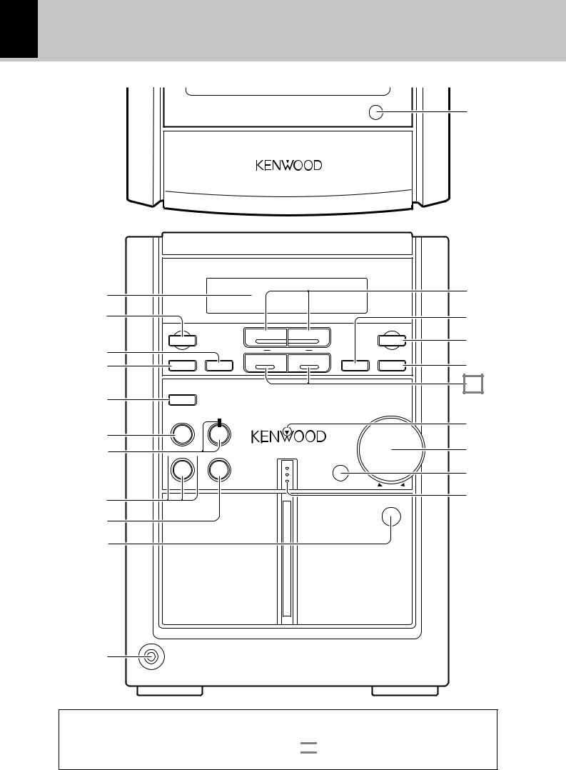
10
Main unit
section |
|
|
Preparation |
2 |
|
|
||
|
3 |
|
|
4 |
|
|
||
|
5 |
|
|
6 |
|
|
7 |
|
|
|
8 |
|
|
9 |
|
|
|
|
0 |
|
|
! |
|
@
Controls and indicators
HM-331 (En/T)
0 push open
1
|
|
|
|
# |
|
|
|
|
$ |
4 |
4 |
CD |
TAPE |
|
|
O.T.E. |
% |
||
TAPE rec |
|
|
||
1 TAPE / preset |
1 |
|
|
|
TUNER / band |
AUX |
|
|
^ |
menu set / demo |
|
repeat |
sound |
|
|
|
|
||
open / close |
|
|
|
& |
|
|
|
|
|
panel |
|
|
|
|
|
VOLUME / multi control |
||
tape |
CD |
|
* |
|
|
||
EQ. |
6 |
|
|
2direction 2 |
on/standby |
|
( |
|
|
||
TAPE |
STOP |
|
) |
7 |
|
||
|
d |
|
|
|
o |
|
p |
|
w |
n |
|
|
|
u |
|
|
|
0 |
¡ |
|
|
push open |
|
Auto Reverse
phones
About the one-touch operation function
This unit incorporates the one-touch operation function for the user's convenience.
With this function, pressing any key enclosed in 
 while the unit is in standby mode immediately start playback (or reception).
1CD cover open key (0)
Press to open the CD player cover.
2 Display |
|
3 Tape record key (TAPE rec) |
£ |
Press to start recording. Pressing the key during recording stops it after leaving a non-recorded space (blank) of about 4 seconds.
4“set/demo” key
Press to set or enter an item selected with the “VOLUME/ multi control“.
Used for demonstration ON/OFF.
5“menu” key
Press to switch the function of the “VOLUME/multi control (up/down)” knob.
This key is also used when setting the time of the day.
6 |
“panel open / close” key |
|
7 |
”tape EQ” key |
|
8 CD play/pause key (CD 6)/indicator |
^ |
|
Press to select the CD input and start CD playback. Press during CD playback to let it pause temporarily.
9 Tape play key (TAPE)/
TAPE direction indicator 0 Stop key (7)
!Cassette holder
Press the area marked “0push OPEN” to load or eject a tape.
@“phones” jack
Headphones with a stereo mini plug (optional) can be connected.
Controls and indicators 11
HM-331 (En/T)
#CD Skip (4, ¢)/TAPE (1, ¡) keys &)
During CD operation :
Press to skip tracks in the forward or backward direction.
During TUNER operation :
Press to receive a preset station.
During TAPE operation :
Press to search in the forward or backward direction.
$ “repeat” key |
° |
Used for repeated playback of CD. |
|
% O.T.E. key |
|
^ “sound” key |
% |
Used for switching the EX.BASS play and LOUDNESS play.
& “TUNER/band” key |
) |
|
|
|
|||
The received broadcasting band is switched. |
|
|
|
Press to select the TUNER input. |
|
Preparation |
|
AUX input key |
|
||
|
|
||
Press to listen to the input source connected to AUX (analog |
|
||
external). |
|
|
|
* Standby / timer indicator |
$ |
section |
|
Light in standby mode of power. |
|
||
|
|
||
Red |
:Normal standby mode |
|
|
Orange |
:O.T.T. standby |
|
|
|
:Program timer standby |
|
|
Green |
:Power ON mode |
|
|
* ( “VOLUME/multi control (up/down)” knob |
$ |
|
|
Normally this is used for volume adjustment. |
|
|
|
) Remote sensor
¡“on/standby” key
The system is switched ON and STANDBY.
* About the VOLUME/multi control (up/down) knob
After selecting the function of this knob with the “menu” key, select the desired control item by turning the “VOLUME/multi control (up/down)” knob. To set or enter the setting of the selected item, press the “set/demo” key.
VOLUME / multi control
menu
set/demo
Turning the knob switches the function as shown
in the character information display. |
|
||||
|
|
|
TAPE RVS. |
? |
( |
|
|
|
|||
|
|
|
O.T.E. |
? |
› |
|
|
|
A. MEMORY (or A. PRESET) ? |
¡ |
|
|
|
|
(Only when the TUNER input is selected) |
||
|
|
|
AUX LEVEL |
? |
‡ |
|
|
|
(Only when the AUX input is selected) |
|
|
|
|
|
BALANCE |
? |
fl |
|
|
|
TIMER SET |
? |
· |
|
|
|
A.P.S. SET |
? |
% |
|
|
|
|||
÷The function of the control knob returns to the normal mode when it has not been operated for 5 seconds.
About the REVOLVING CONTROL PANEL
AUTO
÷The REVOLVING CONTROL PANEL is closed when the power supply is in STANDBY mode.
÷When the power is switched ON, the REVOLVING CONTROL PANEL opens.
÷When the power is ON, the panel opens and closes alternately each time the "panel open / close" key is pressed.
MANUAL
÷When the power is ON, the panel opens and closes alternately each time the "panel open / close" key is pressed.
MANUAL AUTO |
open / close |
REVOLVING CONTROL PANEL |
|
(close state) |
|
|
panel |
|
|
|
ANTENNA |
|
|
|
|
SPEAKERS |
|
|
(6–16Ω ) |
|
FM |
+ |
|
300Ω |
|
FM |
|
L |
75Ω |
|
– |
GND |
AM |
– |
|
|
R+ |
|
|
+ |
DIGITAL |
|
|
OUT |
|
SUPER |
OPTICAL |
|
WOOFER |
|
|
PRE OUT |
MANUAL |
AUTO |
2 |
2 |
2 |
2 |
|
PANEL |
||||
|
OPEN/CLOSE |
|
|
|
|
AUX INPUT
12
Remote control unit
|
1 |
|
|
|
POWER |
|
2 |
SLEEP |
TONE |
SOUND |
|
|
|
|
|
|
|
|
|
1 |
2 |
3 |
TIMER |
|
|
4 |
5 |
6 |
REPEAT |
|
3 |
7 |
8 |
9 |
RANDOM |
section |
|
+10 |
0 |
PGM |
CLEAR |
4 |
TAPE |
O.T.E. |
TIME DISP. DOT DISP. |
||
|
|
|
|
||
|
|
|
|
|
|
Preparation |
|
1 |
¡ |
4P.CALL ¢ |
|
5 |
TA/NEWS |
PTY |
AUX |
% |
|
|
TAPE |
TUNER |
CD |
7 |
|
|
|
2 3 |
BAND |
6 |
|
|
6 |
|
|
|
|
|
7 |
SET |
ENTER |
MUTE |
VOLUME |
|
|
||||
|
8 |
|
|
|
fi |
REMOTE CONTROL UNIT
RC-F0503E
Controls and indicators
HM-331 (En/T)
The keys on the remote control unit with the same names as on the main unit have the same function as the keys on the main unit.
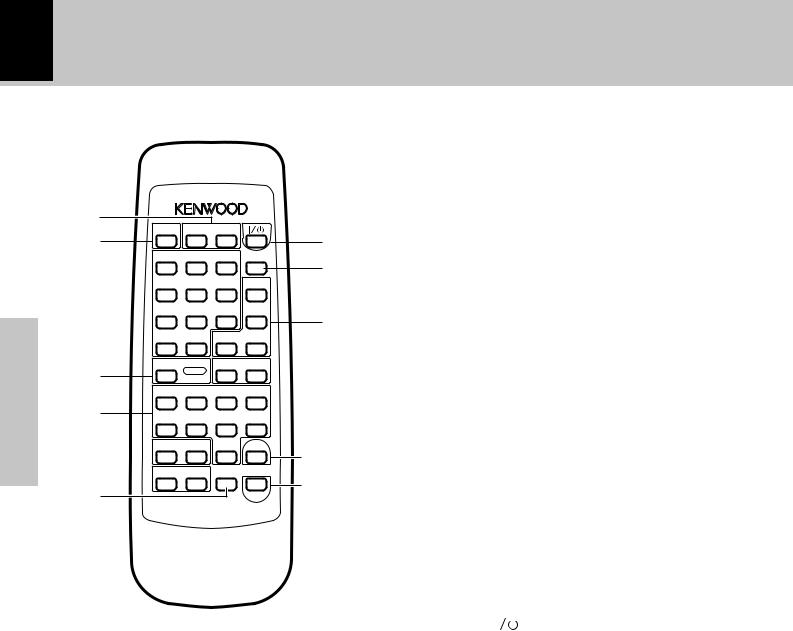
5 Basic operation keys
Fast forward, fast reverse keys (1, ¡)
|
|
During CD or TAPE operation: |
&( |
|
|
Press to search in the forward or backward direction. |
|
9 |
During TUNER operation: |
) |
|
0 |
Press to select a radio station. |
|
|
P.CALL/skip keys (4, ¢) |
|
||
|
|
|
|
|
|
During CD operation : |
& |
|
|
Press to skip tracks in the forward or backward direction. |
|
! |
During TUNER operation: |
) |
|
|
|
Press to select a radio station. |
|
|
|
TAPE 2 3 key |
|
@ |
TUNER BAND key |
|
|
CD 6 key |
|
||
|
|
|
|
|
|
Stop key (7) |
|
|
|
AUX key |
|
|
|
6 RDS-related keys (For Europe and U.K.) |
|
|
|
TA/NEWS key |
⁄ |
|
# |
Used at the time of EON reservation. |
ª |
|
PTY key |
||
|
|
||
|
|
Used at the time of program type detection. |
|
|
|
7 SET key |
|
|
|
Press to set or enter an item selected with the “VOLUME/ |
|
|
|
multi control“. |
|
|
|
ENTER key |
¡ |
It is used to enter the preset station memory in the tuner.
8 MUTE key |
% |
This is used to suppress the sound temporarily.
Europe, and U.K.
RC-F0503E (Infrared ray system)
Other countries
RC-F0503 (Infrared ray system) |
|
1 TONE key |
fl |
This is used to adjust the tone. |
|
SOUND key |
% |
Used for switching the EX.BASS play and LOUDNESS play.
2 SLEEP key |
w |
This is used to set the sleep timer. |
|
3Numeric keys
These are used to select CD tracks and as preset call keys for the tuner.
4 TAPE O.T.E. key |
› |
These keys are used for recording of a CD onto tape with a one-touch operation.
Press either key during CD playback to record the currently played track onto tape. Press in stop mode to record the entire CD onto tape.
9 POWER ( |
|
) key |
$w |
|
|||
|
The system is switched ON and STANDBY.
This key is also used to activate or cancel the timer program execution.
0 TIMER key |
w |
Used to select the timer. |
|
! Keys related to CD |
|
REPEAT key |
° |
This is used for repeated playback. |
|
RANDOM key |
§ |
Playback of the CD tracks in random order. |
|
CLEAR key |
¢ |
The programmed track sequence is cleared. |
|
PGM key |
\¢ |
This is used to program the track sequence. |
|
During TUNER operation: |
¡ |
Used to switch the tuning mode between “AUTO” (auto tuning, stereo reception) and Manual (manual tuning, monaural reception).
@TIME DISP. key
Press to switch the time information displayed during CD playback.
DOT DISP. key |
¶ |
Used for scroll display of the text infomations of CD-TEXT compatible disc.
# VOLUME (%,fi) keys
Operation of remote control unit |
|
13 |
|||
|
|
|
|
|
|
|
|
|
HM-331 (En/T) |
||
|
|
|
|
|
|
|
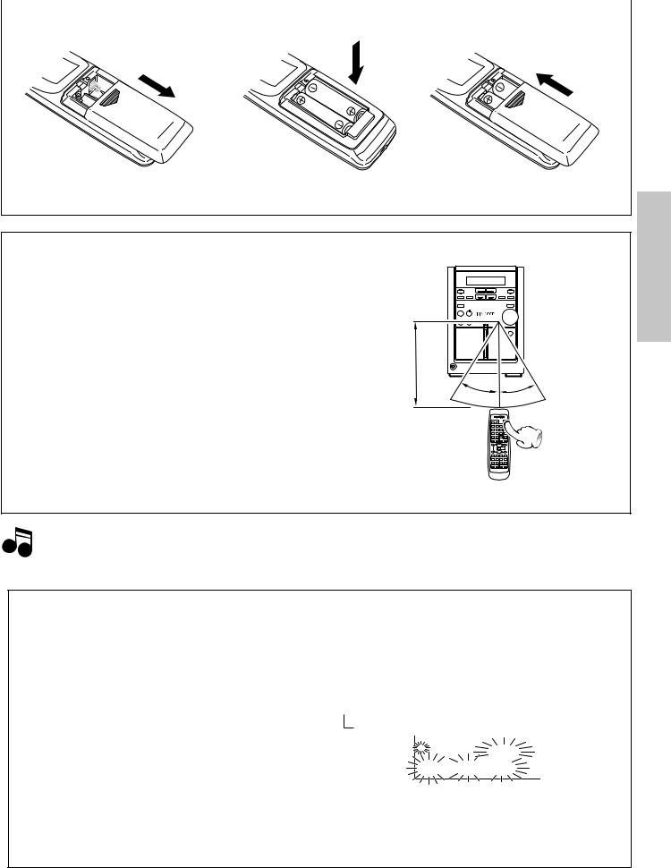
Loading batteries |
|
|
|
|
|
1 Remove the cover. |
2 Insert batteries. |
3 Close the cover. |
||
÷Insert two R6 (“AA”-size) batteries following the polarity indications.
Operation
After plugging the power cord of this unit, press the POWER (

 ) key of the remote control unit to turn the system ON. When the system is turned ON, press the key of the function to be operated.
Operating |
range |
|
Remote sensor |
(approx.) |
2 |
2 |
6m
30˚ 30˚
30˚
÷When pressing more than one remote control keys successively, press the keys securely by leaving an interval of 1 second or more between keys.
section Preparation
1.The provided batteries are intended for use in operation checking, and their service life may be short. Notes 2.When the remote controllable distance becomes short, replace both of the batteries with new ones.
3.If direct sunlight or the light of a highfrequency fluorescent lamp (inverter type, etc.) is incident to the remote sensor, malfunction may occur. In such a case, change the installation position to avoid malfunction.
Channel space switching
(Except for the United Kingdom and Australia)
The space between radio channels has been set to the one that prevails in the area to which the system is shipped. However, if the current channel space setting does not match the setting in the area where the system is to be used, for instance when you move from area 1 or area 2 shown in the following table or vice versa, proper reception of AM/FM broadcasts cannot be expected. In this case, change the channel space setting in accordance with your area by referring to the following table.
|
Area |
CHANNEL |
|
Space Frequency |
|
|
|
|
1 |
USA, Canada and South |
FM: 100 kHz |
|
American countries |
AM: 10 kHz |
2 |
Other countries |
FM: 50 kHz |
|
|
AM: 9 kHz |
1Turn power on.
2Press the TUNER/band key
3Select the mode by using the "repeat" key.
Each press switches the space frequency alternately.
 1 "FM 50 kHz" (FM 50 kHz, AM 9 kHz) 2 "FM 100 kHz" (FM 100 kHz, AM 10 kHz)
FM |
TRACK NO. TOTAL AUTO TUNED |
STEREO |
0 2 1 1 9 0 5 0 |
|
|
AM |
kHz |
|
PM |
MHz BEST HITS |
C H N S P A C E • •
Blinks.
4Establish the selection by pressing the "set/ demo" key.
14 Let's put out some sound
HM-331 (En/T)
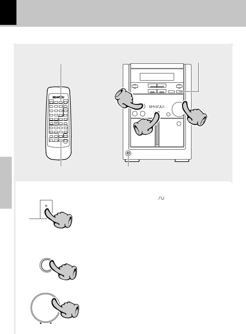
Basic use method
Basic section
Bass and treble compensation |
"sound" key |
2


2 |
2 |
|
3 |
|
1 |
Muting the sound temporarily Listening through headphones
|
|
|
|
|
|
|
|
|
|
|
|
1. Set the “on/standby” key to ON (STANDBY). |
|||
|
|
|
|
|
|
|
|
|
|
|
|
||||
|
|
|
|
on/standby |
|
When the “on/standby” key ( |
|
) is pressed while the unit is ON, |
|||||||
|
|
|
|
|
|
||||||||||
|
|
|
|
|
|
|
|
|
|
|
|
the unit is switched off. |
|
|
|
|
|
|
|
|
|
|
|
|
1 |
|
|
÷ Pressing the CD 6, AUX, TAPE or “TUNER/band” key also turns power |
|||
|
|
|
|
|
|
|
|
|
|
|
on and starts playback (reception) of the corresponding input. (One-touch |
||||
|
|
|
|
|
|
|
|
|
|
|
|||||
|
|
|
|
|
|
|
|
|
|
|
operation) |
|
|
|
|
|
|
|
|
|
|
|
|
|
|
|
|
÷ When the CD or TAPE input is selected while the corresponding disc or tape |
|||
|
|
|
|
|
|
|
|
|
|
|
|
has been loaded, it immediately starts to play. |
|||
|
|
|
|
|
|
|
|
|
|
|
|
|
|||
|
|
Example: |
|
|
|
2. Selecting the desired output. |
|||||||||
|
|
To select the CD input |
|
|
|
|
|
|
|||||||
|
|
|
|
|
|
|
|
|
Lights |
|
TUNER (Broadcasts) |
) |
|
||
|
|
|
|
|
|
|
|
|
|
|
|
CD |
^ |
|
|
|
|
|
|
|
CD |
|
|
|
TAPE |
* |
|
||||
|
|
|
|
6 |
2 |
|
|
AUX (External input) |
8÷ Pressing the CD 6, AUX, TAPE or |
||||||
|
|
|
|
|
|
|
|
|
|
|
|||||
|
|
|
|
|
|
|
|
|
|
|
|
|
|
“TUNER/band” key selects the cor- |
|
|
|
|
|
|
|
|
|
|
|
|
|
|
|
|
responding input. |
|
|
|
|
|
|
|
|
|
|
|
|
|
|
|
|
|
|
VOLUME / multi control |
|
3. Volume adjustment. |
|
|
|
||||||||
|
|
|
|
|
|
|
|||||||||
|
|
|
|
|
|
|
|
|
3 |
|
|
|
|
|
÷ Quick turning produces a larger |
|
|
|
|
|
|
|
|
|
|
|
|
|
|
change amount. (Dynamic rotary vol- |
|
|
|
|
|
|
|
|
|
|
|
|
|
|
|
ume control function) |
|
|
|
do |
|
|
|
|
|
|
|
|
|
|
|
|
÷ The display shows a reference value. |
|
|
w |
n |
|
|
|
|
|
p |
|
|
|
|
|
|
|
|
|
|
|
|
|
|
u |
|
|
|
|
|
||
|
The volume |
|
|
|
|
|
The volume |
|
|
|
|
|
|||
|
decreases |
|
|
|
|
|
|
increases |
|
|
|
|
|
||
|
|
|
|
|
|
|
|
|
|
|
|
|
|
|
|
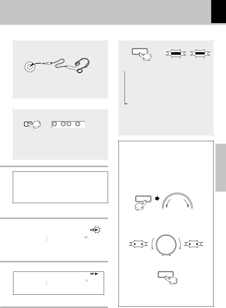
Listening through headphones
Insert the headphone plug into the “phones” jack.
phones
÷Headphones with a stereo mini plug can be connected.
÷The sounds from all speakers are cut off.
Muting the sound temporarily (Remote control unit only)
Blinks
MUTE
 RANDOM
 PGM
PGM  REPEAT
  ALL
ALL 
÷Press again to resume the original volume.
÷This is also cancelled when the volume is changed.
Standby mode
When the standby/timer indicator on the main unit lights in red or orange, a minute current flows for memory protection. This condition is called standby mode.
RANDOM PGM |
REPEAT ALL SLEEP A.P.S. O.T.T. PROG. |
1 2 |
R·D·S EON EON |
|
||
|
TRACK NO. |
TOTAL AUTO TUNED |
|
|
TP TA PTY |
|
FM |
STEREO |
|
||||
8 0 1 8 0 0 0 0 |
|
|
|
|
||
AM |
kHz |
|
||||
PM |
MHz BEST HITS O.T.E. NR T.E. |
|
||||
C D • • • • • • MD EDIT• • • |
||||||
|
|
|
|
|
TITLE SEARCH |
|
|
|
|
|
|
|
|
When CD has been selected.
RANDOM PGM |
REPEAT ALL SLEEP A.P.S. O.T.T. PROG. |
1 2 R·D·S EON EON |
|
|
|
|||
|
|
|
||||||
FM |
TRACK NO. |
TOTAL AUTO TUNED |
STEREO |
TP TA PTY |
|
|
|
|
|
|
|
||||||
|
|
|
|
|||||
|
|
|
|
|||||
8 0 1 8 0 0 1 2 |
|
|
|
|
|
|
||
AM |
kHz |
NR T.E. |
|
|||||
PM |
MHz BEST HITS O.T.E. |
|
||||||
V O L U M E • 2 0 • •TITLE SEARCH
MD EDIT
Volume display
Let's put out some sound 15
HM-331 (En/T)
Bass and treble compensation
sound
EX.BASS |
LOUD |
or
Each press switches the modes as follows.
 1 “EX.BASS” (Extra Bass) lights.
The lowest and highest frequencies are enhanced regardless of the current volume level.
2“LOUD” (Loudness) lights.
The lowest and highest frequencies are enhanced according to the current volume level. (Effective during low-volume listening.)
3 Both indicators off. |
|
Sound enhancement mode is disen- |
|
gaged. |
|
÷ Adjusting the tone while the “LOUD” or “EX.BASS” |
|
indicator is lit turns it off and cancels the sound |
|
enhancement mode. |
fl |
AUTO POWER SAVE function |
|
|
When the unit is ON and the unit is left for 30 min- |
|
|
utes with CD and TAPE not operating, the unit is |
Basic |
|
switched off automatically by this function. This is |
||
convenient when you forgot to switch off the unit. |
||
section |
||
This function can be activated or deactivated by the |
||
following operation. |
||
1 Select “A.P.S. SET?”. |
|
VOLUME / multi control
menu
(Press the “set/demo” key while the “?” mark is blinking.)
2 Select.
A.P.S. off |
VOLUME / multi control |
A.P.S. on |
||
|
|
|
||
A.P.S. |
|
|
|
A.P.S. |
Goes off |
d |
|
|
Lights |
|
o |
u |
|
|
|
|
wn |
|
|
|
|
|
p |
|
3 Set it.
set/demo
÷When the TUNER or AUX input is selected, APS operates only when the volume is set to zero or when MUTE is on.
 Loading...