


KVT-815DVD KVT-745DVD KVT-715DVD
MONITOR WITH DVD RECEIVER
INSTALLATION MANUAL
MONITEUR AVEC RÉCEPTEUR DVD
MANUEL D'INSTALLATION
MONITOR CON RECEPTOR DVD
MANUAL DE INSTALACIÓN
MONITOR COM RECEPTOR DVD
MANUAL DE INSTALAÇÃO
© PRINTED IN JAPAN B54-4433-00/00 (K)(AI)
English
Before Installation
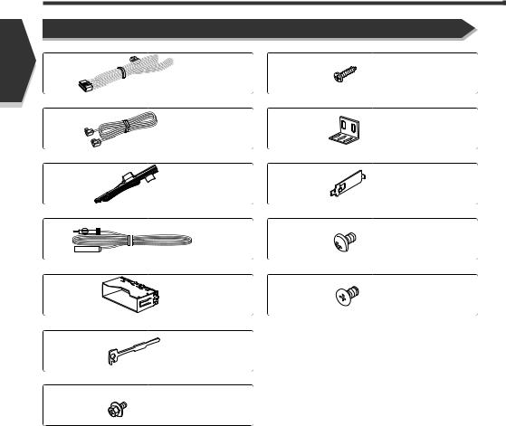
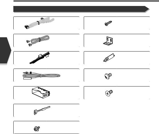
Accessories
1 |
8 |
..........1 |
..........4 |
2 |
9 |
..........1 |
..........2 |
3 |
0 |
..........1 |
..........2 |
4 |
- |
..........1 |
..........4 |
5 |
= |
..........1 |
..........4 |
6
..........2
7
..........4
2 English

Installation Procedure
1.To prevent a short circuit, remove the key from the ignition and disconnect the - battery.
2.Make the proper input and output wire connections for each unit.
3.Connect the speaker wires of the wiring harness.
4.Connect the wiring harness wires in the following order: ground, battery, ignition.
5.Connect the wiring harness connector to the unit.
6.Install the unit in your car.
7.Reconnect the - battery.
8.Press the reset button.
2WARNING
If you connect the ignition wire (red) and the battery wire (yellow) to the car chassis (ground), you may cause a short circuit, that in turn may start a fire. Always connect those wires to the power source running through the fuse box.
2CAUTION
•If your car's ignition does not have an ACC position, connect the ignition wires to a power source that can be turned on and off with the ignition key. If you connect the ignition wire to a power source with a constant voltage supply, as with battery wires, the battery may die.
•If the console has a lid, make sure to install the unit so that the faceplate will not hit the lid when closing and opening.
•If the fuse blows, first make sure the wires aren’t touching to cause a short circuit, then replace the old fuse with one with the same rating.
•Insulate unconnected wires with vinyl tape or other similar material. To prevent a short circuit, do not remove the caps on the ends of the unconnected wires or the terminals.
•Connect the speaker wires correctly to the terminals to which they correspond. The unit may be damaged or fail to work if you share the - wires or ground them to any metal part in the car.
•When only two speakers are being connected to the system, connect the connectors either to both the front output terminals or to both the rear output terminals (do not mix front and rear). For example, if you connect the + connector of the left speaker to a front output terminal, do not connect the - connector to a rear output terminal.
•After the unit is installed, check whether the brake lamps, blinkers, wipers, etc. on the car are working properly.
•Mount the unit so that the mounting angle is 30° or less.
English 3

English
Connection
2WARNING
If you connect the ignition wire (red) and the battery wire (yellow) to the car chassis (ground), you may cause a short circuit, that in turn may start a fire. Always connect those wires to the power source running through the fuse box.
Monitor unit
Do not connect.
Wiring harness (Accessory 3)
Connect to the vehicle's parking brake detection switch harness using the supplied relay connector.
2 CAUTION
For the sake of safety, be sure to connect the parking sensor.
PRK SW
|
|
|
|
|
|
|
Ground wire (Black) - (To car chassis) |
|
|
|
|
|
|
|
|
|
|
|
|
|
|
|
|
|
|
|
|||
|
|
|
|
|
|
|
|
|
|
|
|
|
|
|
|
|
|
|
|
|
|
|
|
|
|
||||
|
|
|
|
|
|
|
|
|
|
|
|
|
|
|
|
|
|
|
|
|
|
|
|
|
|
||||
|
|
|
|
|
|
|
|
|
|
|
|
|
|
|
|
|
|
|
|
|
|
|
|
|
|
||||
|
|
|
|
|
|
|
|
|
|
|
|
|
|
|
|
|
|
|
|
|
|
|
|
|
|
||||
|
|
C |
|
|
|
|
|
|
|
|
|
|
|
|
|
|
|
|
|
|
|
|
|
||||||
|
|
|
|
|
|
|
|
|
|
( 5A ) |
|
||||||||||||||||||
|
|
B |
|
|
Battery wire (Yellow) |
|
|
|
|||||||||||||||||||||
|
|
|
|
|
|
|
|
|
|
|
|
|
|
|
|
|
Accessory 2 |
|
|||||||||||
|
|
|
|
Ignition wire (Red) |
|
|
|
|
|
|
|
|
|
|
|
|
|
|
|||||||||||
|
|
|
|
|
|
|
|
|
|
|
|
|
|
|
|
|
|
||||||||||||
|
|
A |
|
|
|
|
|
|
|
|
|
|
|
|
|
|
|
|
|||||||||||
|
|
|
|
|
|
Accessory 4 |
|
|
|
|
|
|
FM/AM antenna input |
|
|||||||||||||||
|
|
|
|
|
|
|
|
|
|
|
|
|
|
|
|
||||||||||||||
|
|
|
|
|
|
|
|
|
|
|
|
|
|
|
|
|
|
|
|
|
|
|
|
|
|
|
|
|
|
|
|
|
|
|
|
|
|
|
|
|
|
|
|
|
|
|
|
|
|
|
|
|
B |
Battery wire (Yellow) |
|
|
|
|
|
|
|
|
|
|
|
|
|
|
|
|
|
|
|
|
|
|
|
|
|
|
|
|
|
|
|
|
|
|
|
|
|
|
|
|
|
|
|
|
|
|
|
|
|
|
To car light control switch |
Dimmer control wire (Orange/White) |
|
|
|
|
|
|
|
|
|
|
|
|
|
|
|
|
|
|
|
|
|
|
|
|
|
|
|
|
|
|
|
|
|
Ignition key switch |
|
|
|
||||||||||||||||
|
|
|
|
|
|
|
|
|
|
|
|
|
|
|
|
|
|
|
|
|
ACC |
|
|
|
|
|
|
|
|
|
|
|
|
|
|
|
|
|
|
|
|
|
|
|
|
|
|
A |
C |
Ground wire (Black) - (To car chassis) |
|
Car fuse |
|
|
|
|
|
|
|
|
|
|
|
|
|
|
|
|
|
|
|
|
|
B |
Depending on what antenna you are using, |
Motor antenna control wire |
|
box |
|
|
|
|
|
|
|
|
|
|
|
|
|
|
|
|
|
|
|
|
|
|
connect either to the control terminal of the motor |
(Blue) |
|
|
|
|
|
|
|
|
|
|
|
|
|
|
|
|
Car fuse box |
||||||||||
|
|
|
|
|
|
|
|
|
|
|
|
|
|
|
antenna, or to the power terminal for the booster |
|
|||||||||
(Main fuse) |
|
|
|
|
|
|
|
|
|
|
|
|
|
|
|
|
|||||||||
|
|
|
|
|
|
|
|
|
|
|
|
|
|
|
|
|
|
|
|
|
|
amplifier of the film-type antenna. |
|
||
|
|
|
|
|
|
|
|
|
|
|
|
|
|
|
|
|
|
|
|
|
|
|
Power control wire |
||
|
|
|
|
|
|
|
|
|
|
|
|
|
|
|
|
C |
When using the optional power amplifier, |
(Blue/White) |
|||||||
|
|
|
|
|
|
|
|
|
|
|
|
|
|
|
|
||||||||||
|
|
|
|
|
|
|
|
|
|
|
|
|
|
|
|
|
|
|
|
|
|
|
connect to its power control terminal. |
|
|
|
+ |
|
|
|
|
– |
|
|
|
|
|
|
|
|
|
|
|
|
|
|
External amplifier control wire |
||||
|
Battery |
To "EXT.AMP.CONT." terminal of the amplifier |
(Pink/Black) |
||||||||||||||||||||||
|
|
|
|
|
|
|
|
|
|
|
|
|
|
|
|
|
|
|
|
|
|
|
having the external amp control function. |
|
|
4 English
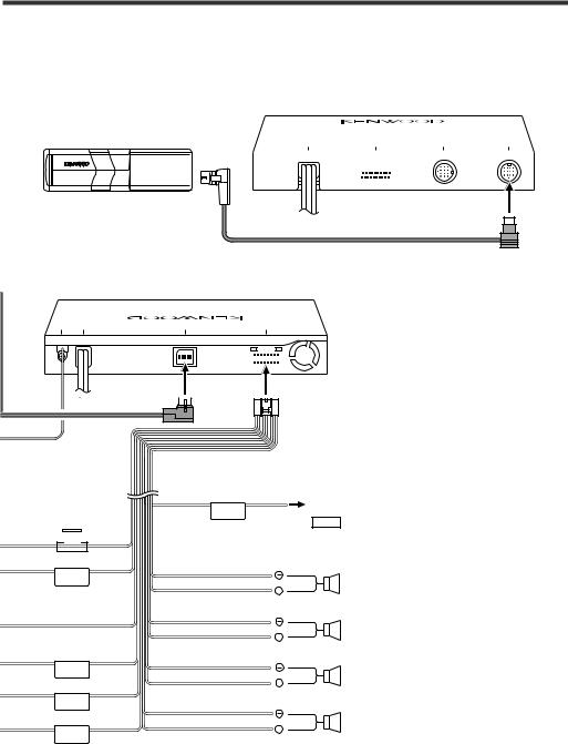
Receiver unit (front side)
PREOUT |
TO TV TUNER I/F |
TO NAVIGATION I/F |
TO 5L-I/F |
|
|
|
|
|
|
|
|
|
|
|
|
|
|
|
|
Disc Changer etc.
Cable (included in the disc changer)
Receiver unit (rear side)
AVOUTPUTANTENNA |
|
|
|
|
|
|
|
|
INPUTFM/AM |
AV |
TOMONITORI/F |
|
|
POWER |
|||
|
|
|
|
|
|
|
|
|
|
|
|
|
|
|
|
|
|
|
|
|
|
|
|
|
|
|
Wiring harness (Accessory 1)
 ( 10A )
ILLUMI
ANT. CONT
P CONT
EXT.CONT
Mute wire (Brown) |
Connect to the terminal that is grounded when either |
|
|
MUTE |
the telephone rings or during conversation. |
|
NOTE |
|
To connect the KENWOOD navigation system, consult your |
|
navigation manual. |
White/Black
To front left speaker
+
White
Gray/Black
To front right speaker
+
Gray
Green/Black
To rear left speaker
+
Green Purple/Black
To rear right speaker
+
Purple
English 5
English
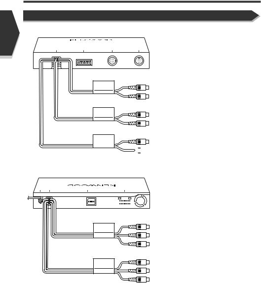
Connection
System Connection
Receiver unit (front side)
PREOUT TO TV TUNER I/F TO NAVIGATION I/F TO 5L-I/F
|
¶ Front Preout |
|
|
Audio left output (White) |
|
|
Audio right output (Red) |
|
|
¶ Rear Preout |
|
REAR |
Audio left output (White) |
|
|
||
|
Audio right output (Red) |
|
SUB |
¶ Sub-woofer (Mono) Preout |
|
Audio left output (White) |
||
WOOFER |
 Audio right output (Red)
Receiver unit (rear side)
AVOUTPUTANTENNA |
|
|
|
|
|
|
|
|
INPUTFM/AM |
AV |
TOMONITORI/F |
|
|
POWER |
|||
|
|
|
|
|
|
|
|
|
|
|
|
|
|
|
|
|
|
|
|
|
|
|
|
|
|
|
¶ Audio/Visual Output
AV OUT |
Visual output (Yellow) |
|
|
|
Audio left output (White) |
|
Audio right output (Red) |
¶ Audio/Visual input
AV IN |
Visual input (Yellow) |
|
|
|
Audio left input (White) |
|
Audio right input (Red) |
6 English
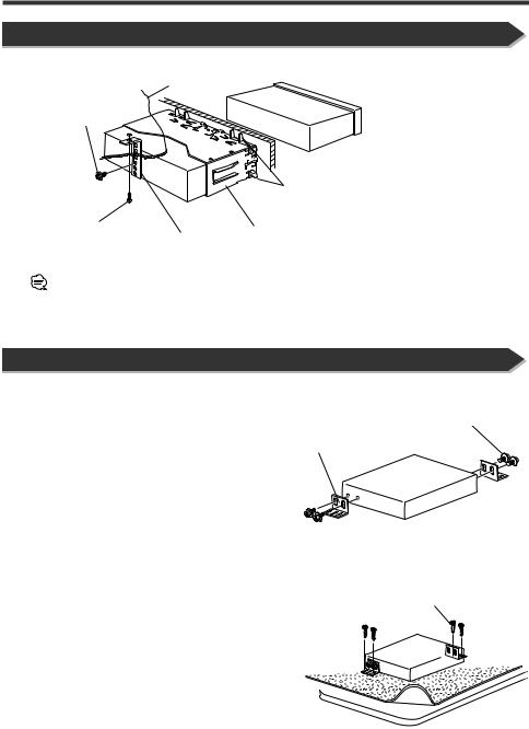
Installation
Installation for Monitor/Player Unit
Firewall or metal support
Screw (M4X8) (commercially available)
Bend the tabs of the mounting sleeve with a screwdriver or similar utensil and attach it in place.
Self-tapping screw |
Accessory 5 |
(commercially available) |
|
|
Metal mounting strap |
|
(commercially available) |
Make sure that the unit is installed securely in place. If the unit is unstable, it may malfunction (eg, the sound may skip).
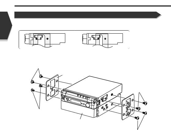
Installation for Receiver unit
1.Attach the installation brackets 9 to the sides of the hideaway unit using the sems bolts 7.
Installation brackets (Accessory 9)
Sems bolts (M4 × 8 mm) (Accessory 7)
2. Use the tapping screw 8 to secure the hideaway unit to the
audio board. Tapping screw (ø4 × 16 mm) (Accessory 8)
English 7
English
Installing in Japanese-Made Cars
■ Installing on Toyota, Nissan or Mitsubishi Car Using Brackets at Holes shown by "¶"
or
Accessory - or =
Bracket
Accessory - or =
Screws (included in audio unit package)
Audio unit or others
Screws (included in audio unit package)
8 English

■ Installation on Toyota Car using Brackets at Holes shown by "¶"
or
unit sides. If so, tighten
Accessory -
Screws (included in audio unit package)

 Screws (included in audio unit package)
3. Bend each end of accessory 0 to fix the bracket.
Use a flat-blade screwdriver or pliers, and bend each accessory tab into the hole of installation bracket to fix the bracket.
English 9
English
Installation
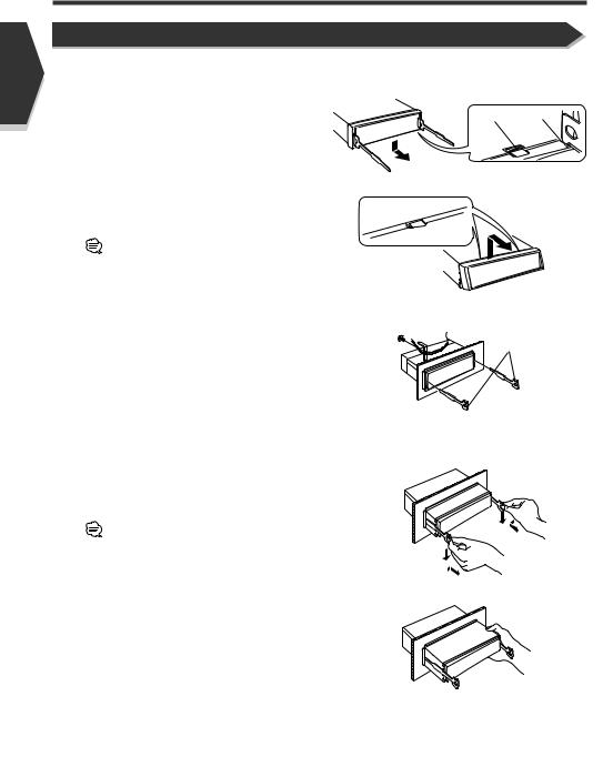
Removing Monitor/Player Unit
■Removing the Hard Rubber Frame (escutcheon)
1.Engage the catch pins on the removal tool 6 and remove the two locks on the lower level.
Lower the frame and pull it forward as shown in the figure.
2.When the lower level is removed, remove the upper two locations.
The frame can be removed from the top side in the same manner.
Lock Catch
 Accessory 6
■ Removing the Unit
1. Refer to the section <Removing the Hard Rubber |
Accessory 6 |
Frame> and then remove the hard rubber frame. |
2. Remove the Hex-head screw with integral washer (M4 × 6) on the back panel.
3.Insert the two removal tools 6 deeply into the slots on each side, as shown.
4.Lower the removal tool toward the bottom, and pull out
the unit halfway while pressing towards the inside.
Be careful to avoid injury from the catch pins on the removal tool.
5.Pull the unit all the way out with your hands, being careful not to drop it.
10 English
French
Avant l’installation
Accessoires
1 |
8 |
..........1 |
..........4 |
2 |
9 |
..........1 |
..........2 |
3 |
0 |
..........1 |
..........2 |
4 |
- |
..........1 |
..........4 |
5 |
= |
..........1 |
..........4 |
6
..........2
7
..........4
12 French
 Loading...