


CD PLAYER
DPF-1010 DPF-2010 DPF-3010
INSTRUCTION MANUAL
KENWOOD CORPORATION
COMPACT
DIGITAL AUDIO
B60-3730-08 00 KO ( T, M, X ) OC
99/12 11 10 9 8 7 6 5 4 3 2 1 98/12 11 10 9 8 7 6 5 4 3
Introduction
Before applying power |
DPF-3010/2010/1010 (En) |
Caution : Read this section carefully to ensure safe operation. |
|
|
|
2 Units are designed for operation as follows.
Australia .................................................................................. |
AC 240 V only |
*Other countries ............................ |
AC 110-120 / 220-240 V switchable |
Europe and U.K. ..................................................................... |
AC 230 V only |
|
|
*AC voltage selection
The AC voltage selector switch on the rear panel is set to the voltage that prevails in the area to which the unit is shipped. Before connecting the power cord to your AC outlet, make sure that the setting position of this switch matches your line voltage. If not, it must be set to your voltage in accordance with the following direction.
Note:
Our warranty does not cover damage caused by excessive line voltage due to improper setting of the AC voltage selector switch.
AC voltage selector switch
|
|
|
|
|
AC 110– |
|
|
|
AC 220– |
120V |
|
|
|
240V |
Move switch lever to match your line voltage with a small screwdriver or other pointed tool.
For the United Kingdom
Factory fitted moulded mains plug
1.The mains plug contains a fuse. For replacement, use only a 13-Amp ASTA-approved (BS1362) fuse.
2.The fuse cover must be refitted when replacing the fuse in the moulded plug.
3.Do not cut off the mains plug from this equipment. If the plug fitted is not suitable for the power points in your home or the cable is too short to reach a power point, then obtain an appropriate safety approved extension lead or adapter, or consult your dealer.
If nonetheless the mains plug is cut off, remove the fuse and dispose of the plug immediately, to avoid a possible shock hazard by inadvertent connection to the mains supply.
IMPORTANT |
|
|
The wires in the mains lead are coloured in accordance with the following code: |
||
Blue |
: Neutral |
|
Brown |
: Live |
|
Do not connect those leads to the earth terminal of a three-pin plug. |
|
|
|
|
|
Safety precautions |
Caution : Read this section carefully to ensure safe operation. |
|
|
|
|
WARNING : TO PREVENT FIRE OR ELECTRIC SHOCK, DO NOT EXPOSE THIS APPLIANCE TO RAIN OR MOISTURE.
CAUTION
RISK OF ELECTRIC SHOCK
DO NOT OPEN
CAUTION: TO REDUCE THE RISK OF ELECTRIC SHOCK, DO NOT REMOVE COVER (OR BACK). NO USER-SERVICEABLE PARTS INSIDE, REFER SERVICING TO QUALIFIED SERVICE PERSONNEL.
THE LIGHTNING FLASH WITH ARROWHEAD SYMBOL, WITHIN AN EQUILATERAL TRIANGLE, IS INTENDED TO ALERT THE USER TO THE PRESENCE OF UNINSULATED “DANGEROUS VOLTAGE” WITHIN THE PRODUCT’S ENCLOSURE THAT MAY BE OF SUFFICIENT MAGNITUDE TO CONSTITUTE A RISK OF ELECTRIC SHOCK TO PERSONS.
THE EXCLAMATION POINT WITHIN AN EQUILATERAL TRIANGLE IS INTENDED TO ALERT THE USER TO THE PRESENCE OF IMPORTANT OPERATING AND MAINTENANCE (SERVICING) INSTRUCTIONS IN THE LITERATURE ACCOMPANYING THE APPLIANCE.
REQUIREMENT BY NEDERLAND GAZETTE
Batteries are supplied with this product. When they empty, you should not throw away. Instead, hand them in as small chemical waste.
The marking of products using lasers (Except for some areas)
CLASS 1
LASER PRODUCT
The marking is located on the rear panel and says that the component uses laser beams that have been classified as Class 1. It means that the unit is utilizing laser beams that are of a weaker class. There is no danger of hazardous radiation outside the unit.
DPF-3010/2010/1010 (En)
Unpacking
Unpack the unit carefully and make sure that all accessories are put aside so they will not be lost.
Examine the unit for any possibility of shipping damage. If your unit is damaged or fails to operate, notify your dealer immediately. If your unit was shipped to you directly, notify the shipping company without delay. Only the consignee (the person or company receiving the unit) can file a claim against the carrier for 3 shipping damage.
We recommend that you retain the original carton and packing materials for use should you transport or ship the unit in the future.
Keep this manual handy for future reference.
Special features
Advanced technologies incorporated in pursuit of improved sound quality and stability
¶D.R.I.V.E. (Dynamic Resolution Intensive Vector Enhancement) IC is built in for drastic reduction of distortion at small signal level. (DPF-3010 only)
¶High-performance 1-bit D/A converter achieving a 20-bit resolution. (DPF-3010 only)
Convenient features for dubbing CD onto tape
¶ |
CD peak search for setting the recording level that does not cause distortion. |
( |
¶ Edit function for rearranging tracks according to the tape length so that no music is interrupted |
||
|
in the middle. |
* |
Easy operation functions |
|
|
|
|
¶ |
Auto space function. |
% |
|
|||
|
¶ Easy operation functions allow systematic operation with other KENWOOD components |
||
|
|
connected through the system control connection. |
8 |
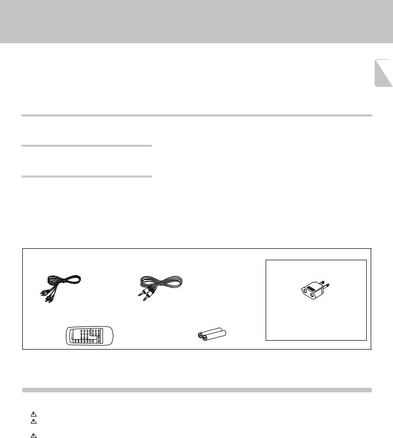
Accessories
Audio cord ........................ |
(1) |
System control cord ............ |
(1) |
Remote control unit |
......... (1) |
Batteries (R6/AA) .............. |
(2) |
(DPF-3010/DPF-2010 only) |
(DPF-3010/DPF-2010 only) |
|
|
REMOTE CONTROL UNIT |
RC-P0305 |
|
|
AC plug adaptor .............. |
(1) |
Use to adapt the plug on the power cord to the shape of the wall outlet. (Accessory only for regions where use is necessary.)
Contents
Caution: Read the pages marked  carefully to ensure safe operation.
Introduction .................................................................. |
2 |
Before applying power ................................................ |
2 |
Safety precautions ....................................................... |
2 |
Special features ................................................................... |
3 |
IMPORTANT SAFEGUARDS ........................................ |
4 |
System connections .................................................... |
6 |
To use the headphone ......................................................... |
7 |
Maintenance ................................................................. |
9 |
Controls and indicators ............................................. |
10 |
Operation of remote control unit ............................. |
11 |
Normal play (TRACK mode) ...................................... |
12 |
Playing tracks in order from track No.1 .......................... |
12 |
Playback from desired track ............................................. |
13 |
Skipping tracks .................................................................. |
13 |
Searching ........................................................................... |
13 |
Time display on CD player (TIME DISPLAY) .................... |
13 |
Programmed play (PGM mode) ................................ |
14 |
To check or change the programmed tracks .................. |
15 |
To add a track to the program ......................................... |
15 |
To clear tracks from the program .................................... |
15 |
Repeated playback .................................................... |
16 |
To repeat only the programmed tracks ........................... |
16 |
To repeat the entire disc ................................................... |
17 |
Editing ......................................................................... |
18 |
Playing or recording the edited contents ....................... |
18 |
To check the edited contents ........................................... |
19 |
To clear the edited contents ............................................. |
19 |
Peak search ........................................................................ |
19 |
Playback in random order (Random playback) ....... |
20 |
Timer operations ........................................................ |
21 |
In case of difficulty ..................................................... |
22 |
Specifications ............................................................. |
23 |
IMPORTANT SAFEGUARDS
Please read all of the safety and operating instructions before operating this appliance. Adhere to all warnings on 4 the appliance and in the instruction manual. Follow all the safety and operating instructions. These safety and operating instructions should be retained for future
reference.
1.Power sources – The appliance should be connected to a power supply only of the type described in the instruction manual or as marked on the appliance. If you are not sure of the type of power supply to your home, consult your appliance dealer or local power company. For appliances intended to operate from battery power, or other sources, refer to the instruction manual.
2.Power-cord protection – Power-supply cords should be routed so that they are not likely to be walked on or pinched by items placed upon or against them, pay particular attention to cords at plugs, convenience receptacles, and the point where they exit from the appliance.
Never pull or stretch the cord.
3.CAUTION – Polarization – This appliance may be equipped with a polarized alternating-current line plug (a plug having one blade wider than the other). This plug will fit into the power outlet only one way. This is a safety feature. If you are unable to insert the plug fully into the outlet, try reversing the plug. If the plug should still fail to fit, contact your electrician to replace your obsolete outlet. Do not defeat the safety purpose of the polarized plug.
4.Ventilation – Slots and openings in the cabinet are provided for ventilation and to ensure reliable operation of the appliance and to protect it from overheating, and these openings must not be blocked or covered. The appliance should be situated so that its location or position does not interfere with its proper ventilation.
To maintain good ventilation, do not put records or a tablecloth on the appliance. Place the appliance at least 10 cm away from the walls.
Do not use the appliance on a bed, sofa, rug or similar surface that may block the ventilation openings. This appliance should not be placed in a built-in installation such as a bookcase or rack unless proper ventilation is provided or the manufacturer’s instructions have been adhered to.
5.Water and moisture – The appliance should not be used near water - for example, near a bathtub, washbowl, kitchen sink, laundry tub, in a wet basement, or near a swimming pool, etc.
 Caution : Read this page carefully to ensure safe operation.
DPF-3010/2010/1010 (En)
6.Temperature – The appliance may not function properly if used at extremely low, or freezing temperatures. The ideal ambient temperature is above +5°C (41°F).
7.Heat – The appliance should be situated away from heat sources such as radiators, heat registers, stoves, or other appliances (including amplifiers) that produce heat.
8.Electric shock – Care should be taken so that objects do not fall and liquid is not spilled into the enclosure through openings. If a metal objects, such as a hair pin or a needle, comes into contact with the inside of this appliance, a dangerous electric shock may result. For families with children, never permit children to put anything, especially metal, inside this appliance.
9.Enclosure removal – Never remove the enclosure. If the internal parts are touched accidentally, a serious electric shock might occur.
10.Magnetic fields – Keep the appliance away from sources of magnetic fields such as TV sets, speaker systems, radios, motorized toys or magnetized objects.
11.Cleaning – Unplug this appliance from the wall outlet before cleaning. Do not use volatile solvents such as alcohol, paint thinner, gasoline, or benzine, etc. to clean the cabinet. Use a clean dry cloth.
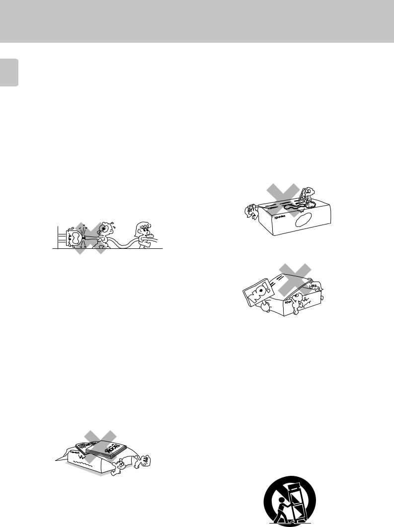
12.Accessories – Do not place this appliance on an unstable cart, stand, tripod, bracket, or table. The appliance may fall, causing serious injury to a child or adult, and serious damage to the appliance. Use only with a cart, stand, tripod, bracket, or table recommended by the manufacturer, or sold with the appliance. Any mounting of the appliance should follow the manufacturer’s instructions, and should use a mounting accessory recommended by the manufacturer. An appliance and cart combination should be moved with care. Quick stops, excessive force, and uneven surfaces may cause the appliance and cart combination to overturn.

 Caution : Read this page carefully to ensure safe operation.
DPF-3010/2010/1010 (En)
13.Lightning – For added protection for this appliance during a lightning storm, or when it is left unattended and unused for long periods of time, unplug it from the wall outlet and disconnect the antenna or cable system. This will prevent damage to the appliance due to lightning and power-line surges.
14.Abnormal smell – If an abnormal smell or smoke is detected, immediately turn the power OFF and unplug the appliance from the wall outlet. Contact your dealer or nearest service center.
15.Damage requiring service – The appliance should be serviced by qualified service personnel when:
A.The power-supply cord or the plug has been damaged.
B.Objects have fallen, or liquid has been spilled into the appliance.
C.The appliance has been exposed to rain or water.
D.The appliance does not appear to operate normally by following the instruction manual. Adjust only those controls that are covered by the instruction manual as an improper adjustment of other controls may result in damage and will often require extensive work by a qualified technician to restore the appliance to its normal operation.
E.The appliance has been dropped, or the enclosure damaged.
F.The appliance exhibits a marked change in performance.
16.Servicing – The user should not attempt to service the appliance beyond that described in the instruction manual. All other servicing should be referred to qualified service personnel.
17.Outdoor antenna grounding – If an outside antenna is connected to the appliance, be sure the antenna system is grounded so as to provide some protection against voltage surges and built up static charges. Article 810 of the National Electrical Code ANSI/ NFPA 70, provides information with respect to proper grounding of the mast and supporting structure, grounding of the lead-in wire to an antenna discharge unit, size of grounding conductors, location of antenna discharge unit, connection to grounding electrodes, and requirements for the grounding electrode. See Figure.
EXAMPLE OF ANTENNA GROUNDING AS PER
NATIONAL ELECTRICAL CODE
|
ANTENNA |
|
LEAD IN WIRE |
GROUND |
|
CLAMPS |
|
|
ANTENNA |
|
DISCHARGE UNIT |
|
(NEC SECTION 810-20) |
ELECTRIC |
|
SERVICE |
GROUNDING CONDUCTORS |
EQUIPMENT |
|
|
(NEC SECTION 810-21) |
|
GROUND CLAMP |
|
POWER SERVICE GROUNDING |
|
ELECTRODE SYSTEM |
|
(NEC ART 250, PART H) |
NEC – NATIONAL ELECTRICAL CODE |
|
18.Power lines – An outside antenna system should not be located in the vicinity of overhead power lines or other electric light or power circuits, or where it can fall into such 5 power lines or circuits. When installing an outside antenna system, extreme care should be taken to keep from touching such power lines or circuits as contact with them might be fatal.
19.AC outlets – Do not connect other audio equipment with a power consumption larger than that specified to the AC outlet on the rear panel. Never connect other electrical appliances, such as an iron or toaster, to it to prevent fire or electric shock.
20.Overloading – Do not overload wall outlets, extension cords, or integral convenience receptacles as this can result in a risk of fire or electric shock.
21.Attachment – Do not use attachments not recommended by the appliance manufacturer as they may cause hazards.
22.Replacementparts–Whenreplacementpartsarerequired, be sure the service technician has used replacement parts specified by the manufacturer or have the same characteristics as the original parts. Unauthorized substitutions may result in fire, electric shock, or other hazards.
23.Safety check – Upon completion of any service or repairs to this appliance, ask the service technician to perform safety checks to determine that the appliance is in proper operating condition.
Notes:
1.Item 3 is not required except for grounded or polarized equipment.
2.Item 17 and 18 are not required except for units provided with antenna terminals.
3.Item 17 complies with UL in the U.S.A.

System connections
Caution:
6 Do not plug in the power lead until all connections are completed.
Make connections as shown below.
When connecting the related system components, refer also to the instruction manuals of the related components.
DPF-3010/2010/1010 (En)
Malfunction of microcomputer
If operation is not possible or erroneous display appears even though all connections have been made properly, reset the microcomputer referring to “In case of difficulty”. ™
Caution regarding placement
To maintain proper ventilation, be sure to leave a space around the unit (from the largest outer dimensions including projections) equal to, or greater than, shown below.
Left and right panels: 10 cm Rear panel: 10 cm
DIGITAL OUTPUT jack (DPF-3010/DPF-2010 only)
|
|
SL 16/XS8 switch 8 |
OUTPUT |
DIGITAL |
SYSTEM CONTROL |
|
OUTPUT |
ƒ |
|
OPTICAL |
|
L |
|
|
|
|
SL 16 XS-8 |
R |
|
|
Remove the |
|
protection cap |
SYSTEM |
when using the |
CONTROL |
|
|
DIGITAL OUTPUT |
|
(OPTICAL) jack. |
System control cord |
CD


 L
L
Audio cord |
R |
Amplifier
DIGITAL
INPUT
OPTICAL
Commercially-available optical fiber cable
MD recorder
To AC outlet
To wall AC outlet
To AC outlet
|
1. |
Connect all cords firmly. If connections are loose there could be loss of sound or noise produced. |
Notes |
2. |
When plugging and unplugging connection cords, be sure to first remove the power cord from the AC outlet. Plugging/unplugging |
|
|
connection cords without removal of the power cord can cause malfunctions or damage to the unit.
DPF-3010/2010/1010 (En)
7
Connection to a general-use amplifier
Use the provided audio cords to connect the OUTPUT jacks of this unit to the CD input jacks (or AUX jacks) of the amplifier.
Connection to digital amplifier or MD (only for DPF-3010/2010)
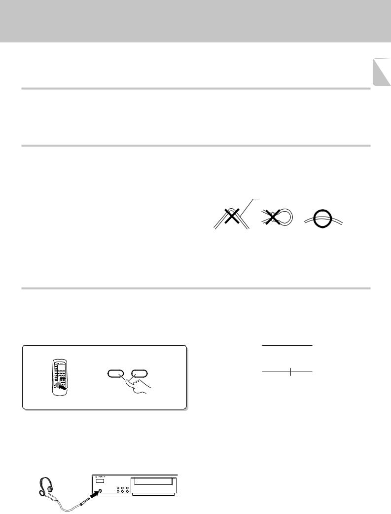
Connect the DIGITAL OUTPUT (OPTICAL) jack to the digital input jack of the amplifier, DAT recorder, MD recorder, etc., using an optical fiber cable which are commercially available in audio stores.
÷When using an optical fiber cable to connect this unit to a digital |
Optical fiber cable |
amplifier, insert the plug straight into the jack until a snap sound is |
|
heard. |
|
÷Be careful not to bend, coil, or bundle the optical fiber cable. |
|
÷Optical fiber cables available on the market may not always be able to |
|
be used with this player. If your cord cannot be used with this unit, |
|
consult the store from which you purchased the cord or your nearest |
|
dealer. |
|
Adjusting the output levels of the output jacks and headphone output (only for DPF-3010/2010)
The OUTPUT level (UP/DOWN) keys of the remote control unit can adjust the output levels from the LINE/OUT jacks and PHONES jack (DPF-3010 only) of the unit.
OUTPUT
DOWN UP
RC-P0305
To use the headphone (only for DPF-3010)
Connect a stereo headphone to the PHONES jack of the CD player. Adjust the sound volume using the remote control unit.
SINGLE TIME
_12 db
Output level
÷It is not favorable for the sound quality to decrease the output level from this unit too much. Use these keys for coordination with other line levels.
÷Adjusting the headphone output level also changes the LINE/OUT level. Do not adjust the output level from this unit particularly during recording.
÷Please note that the sound output is at the maximum level when the power is turned on.

DPF-3010/2010/1010 (En)
8
SYSTEM CONTROL CONNECTIONS
Connecting system control cords after connecting a KENWOOD audio component system lets you take advantage of convenient system control operations.
There are two KENWOOD system control modes. Make connections according to the groups of terminal symbols shown below.
[XS8] Mode : lets you combine F, f, and ƒterminals [SL16] Mode : for 
 terminals only
This unit is compatible with both [XS8] and [SL16] modes.
÷When all units in system control connection are set to [XS8] mode, set the SYSREM CONTROL selector switch on the rear to the [XS8] side and connect.
÷When all units in system control connection are set to [SL16] mode, set the SYSREM CONTROL selector switch on the rear to the [SL16] side and connect.
SL16 XS 8
SYSREM CONTROL
selector switch
j
÷Do this operation after completing all connections. (Ensure that the unit is set to STANDBY mode.)
SYSTEM CONTROL
SYSTEM CONTROL
SYSTEM CONTROL
SYSTEM CONTROL
SYSTEM CONTROL
1. [SL16] equipment cannot be combined with [XR], [XS], and [XS8]
Notes
equipment for system operations. If your equipment consists of this kind of combination, please do not connect any system control cords. Even without system control cords, normal operations can be carried out without affecting performance.
2. If your amp or receiver does not have a system control terminal, do not connect any system control cords to the system control terminals on the other components.
3.Do not connect system control cords to any components other than those specified by Kenwood. It may cause a malfunction and damage your equipment.
4.Be sure the system control plugs are inserted all the way in to the system control terminals.
SYSTEM CONTROL OPERATIONS
Remote Control
Lets you operate this unit with the system remote control unit supplied with the amplifier or receiver.
Automatic Operation (Except [XR] equipment)
Automatically switches the input selector on the amplifier or receiver when you start playback from this unit.
Synchronized Recording (Except [XR] equipment)
Lets you synchronize recording with the start of playback when recording from CD. Also, the simple CCRS operation lets you make great recordings from CD.
See the operating instructions supplied with your cassette deck and MD recorder for details.
 Loading...