


DCS-7020
DIGITAL STORAGE OSCILLOSCOPES
22
(1) Maximum sampling rate of 40 MS/s (DCS-7040; 20 MS/s with
the DCS-7020) allows advanced waveform obser vations.
(2) 4K-word acquisition memories and 2K-word reference
memories (backed up by a built-in batter y) are provided.
(3) The peak detector function can detect glitch with pulse
duration of 25 ns or more.
(4) The over writing function makes for easy measurements of
jitter, voltage variation, etc.
(5) The external clock input can be used to sample asynchronous
low-speed signals as required.
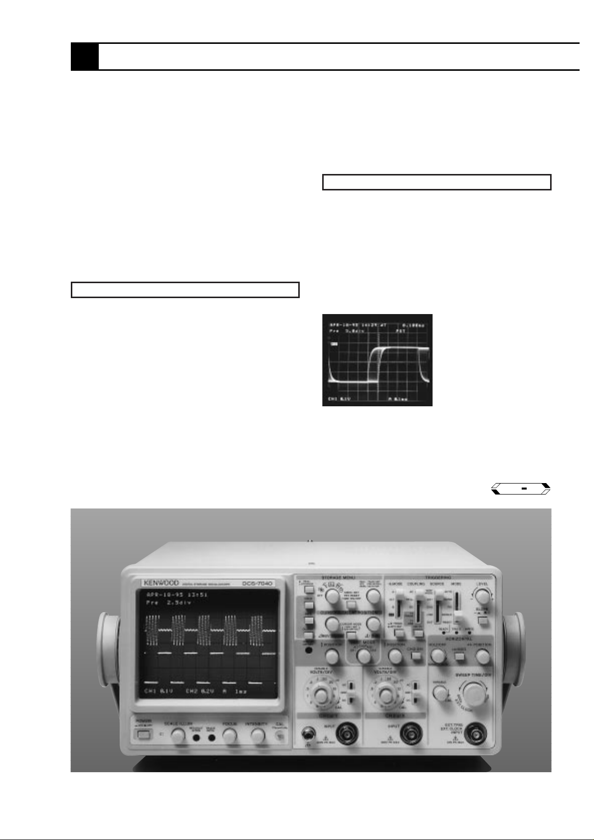
[Overwrite] This mode allows
you to write an input waveform
without erasing the previously
written waveforms. It makes the
observation of the jitter
components in, and amplitude
variations of waveforms easy.
With the storage menu and triggering function
concentrated to assure safe use by anyone engaged in
the production and a clear panel layout showing
operations at a glance, the DCS-7000 Series of
oscilloscopes are easy-to-use models even for
beginners in spite of the many, versatile functions
packed in each unit. The maximum sampling rate of 40
MS/s (DCS-7040) enables advanced waveform
observations, and an analog function (50 MHz) is also
incorporated so that each model can play two roles of
digital and analog. Each channel has a 4K-word
acquisition memory. The peak detector and overwriting
functions are provided in pursuit of a compatibility
between the ease of use and the high functionality.
Optional interfaces can also be installed so the
waveforms displayed on the CRT can be hard-copied
on a plotter or a special printer.
DCS-7000 SERIES
Digital Storage Oscilloscopes
40MS/s 2 Acquisition (Readout Cursors)
DCS-7040
20MS/s 2 Acquisition (Readout Cursors)
DCS-7020
GP IB
OPTION
OUTLINE
FEATURES
23
DIGITAL STORAGE OSCILLOSCOPES
DCS-7000 SERIES
DIGITAL STORAGE OSCILLOSCOPES
DCS-7000 SER ES
External clock input
Sampling can be perfor med in synchronism with the externally
input clock signal. This allows waveform observations
synchronized with signals with inconstant period, such as encoder
pulse and rotar y object signals.
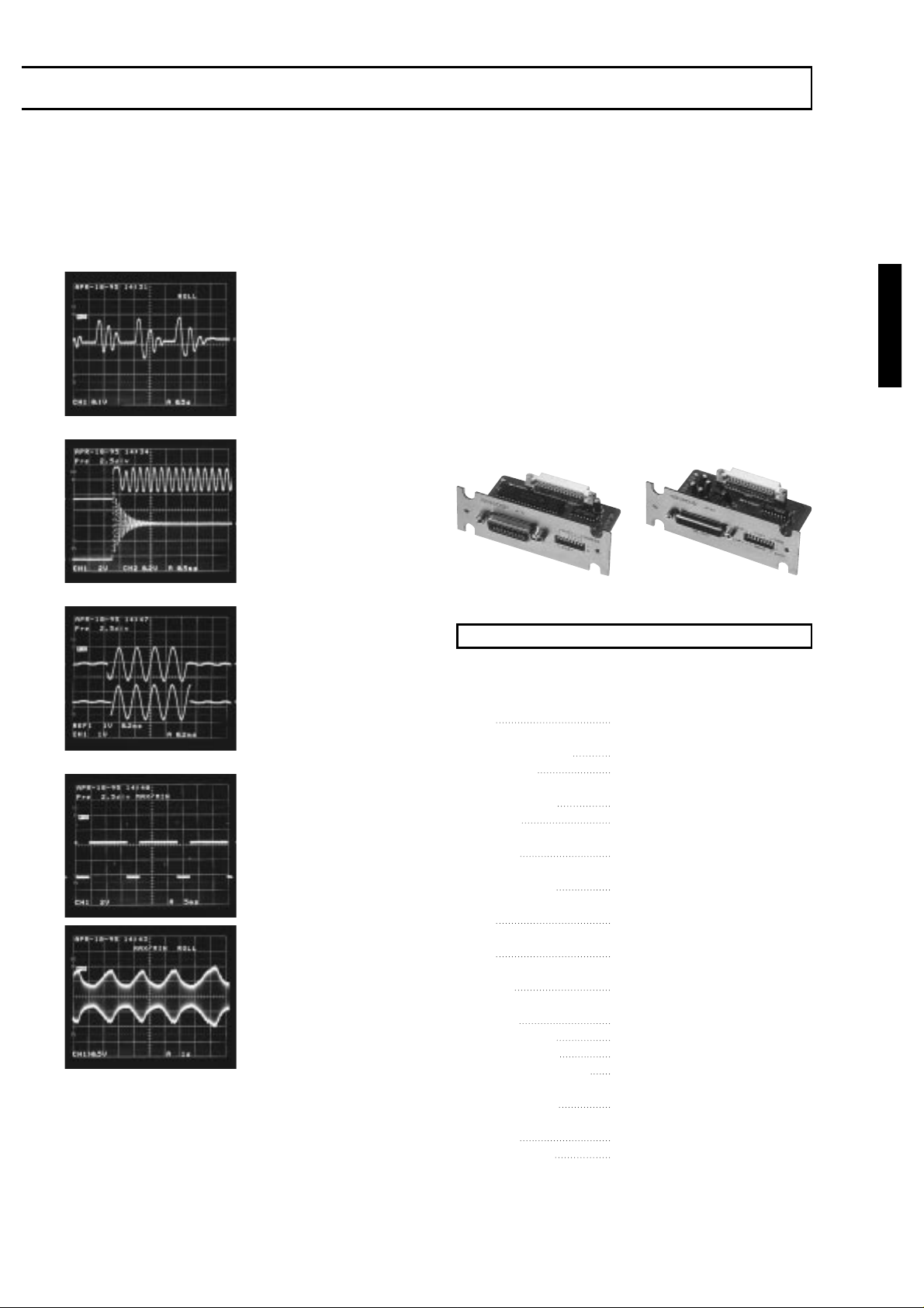
Optional interfaces
Both the DCS-7040 and DCS-7020 can be equipped optionally with
GP-IB or RS-232C interface. This allows you to har d-copy the CRT
display waveforms on a plotter or a special printer as they are.
[Single roll] Setting “Single” in
the roll mode enters the single
roll mode. When the trigger
signal is input in this mode, the
CRT display wavefor m stops
after the data corresponding to
the value set for pre-triggering
has been updated.
[Pre-triggering] The triggering
for storage includes pre-
triggering of up to 20 div in
addition to normal triggering
and delayed-sweep triggering.
This makes it possible to
observe phenomena which
have previously been unable to
be captured.
[2-channel simultaneous sampling]
The 2-channel simultaneous
sampling at the maximum
sampling rate of 40 MS/s (DCS-
7040; 20 MS/s with the DCS-
7020) makes for easy waveform
observations of single-shot
phenomena, transient phenomena,
sudden phenomena, etc.
[Peak detector]
(1) The peak detector function
detects the maximum and
minimum values of signal
waveforms. This mode is
capable of detecting glitches of
25 ns or more regardless of the
sweep rate.
(2) The peak detector function
allows you to observe the
envelopes of amplitude-modulated
signal waveforms.
Memory
Each CH1 and CH2 is equipped with a 4K-word acquisition
memor y and a 2K-word reference memor y. Each acquisition
memory can scr oll the desired position and display it on the CR T.
※Figures inside [ ] are the values for the DCS-7020; all other values are
common.
[Real-time section]
CRT
Type 150mm rectangular, with internal
graticule
Accelerating voltage Approx. 12kV
Effective area 8div.×10div. (1div = 10mm)
Vertical axis (Common for CH1, CH2)
Operating modes CH1, CH2, ADD, ALT, CHOP
Sensitivity 1mV/div., 2mV/div. : ± 5%
5mV/div. to 5V/div. : ±3%
Attenuator 1mV/div. to 5V/div., 1-2-5 step,
(fine adjustment)
Input impedance 1MΩ± 2%, approx. 25pF
Frequency response
DC
DC to 50MHz, (−3dB)(5mV/div to 5V/div.)
DC to 20MHz, (−3dB)(1mV/div, 2mV/div.)
AC
5Hz to 50MHz, (−3dB)(5mV/div to 5V/div.)
5Hz to 20MHz, (−3dB)(1mV/div to 2mV/div.)
Rise time Approx. 7ns (5mV/div. to 5v/div.)
Approx. 17.5ns (1mV/div., 2mV/div.)
Crosstalk Below −40dB (at 1kHz)
Polarity inversion CH2 only
CHOP Frequency Approx. 250kHz
Maximum input voltage 800Vp-p or 400V (DC+ AC peak)
Horizontal axis
Operating modes Set to X-Y mode by H MODE
CH1 : Y-axis、CH2 : X-axis
Sensitivity Same as Vertical axis (CH2)
Input impedance Same as Vertical axis (CH2)
IF-10 IF-20R
SPECIFICATIONS
 Loading...