


79031049800
Kenmore Elite 79031049800, 79031039802, 79031039804, 79031042800, 79031033802 Installation Guide
...
iNSTALLATiON AND SERVICE MUST BEPERFORMED BYA QUALiFiED iNSTALLER.
IMPORTANT: SAVE FOR LOCAL ELECTRICALINSPECTOR'S USE.
READ AND SAVE THESEiNSTRUCTiONS FOR FUTURE REFERENCE.
if the information in this manual is not followed exactly, a fire or
expJosion may resuJt causing property damage, personal injury or death.
FOR YOUR SAFETY:
-- Do not store or use gasoline or other flammable vapors and liquids in the
vicinity of this or any other appliance.
-- WHAT TO DO iF YOU SMELL GAS:
* Do not try to light any appliance.
. Do not touch any eJectrical switch; do not use any phone in your buiJding.
* Immediately calJ your gas supplier from a neighbor's phone. Follow the
gas supplier's instructions.
* If you cannot reach your gas supplier, calJ the fire department.
-- Installation and service must be performed by a qualified instalJer,
service agency or the gas supplier.
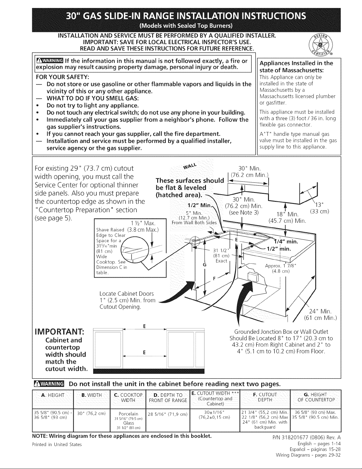
For existing 29" (73.7 cm) cutout
width opening, you must call the
Service Center for optional thinner
side panels. Also you must prepare
the countertop edge as shown in the
"Countertop Preparation" section
(see page 5).
Shave Raised
Edge to Clear
Space for a
31s/16"min
(81 cm)
Wide
Cooktop.
Dimension C in
table.
11/2 Max.
(3.8 cm Max.
These surfaces should
be flat & leveled
(hatched area).
1/2" Min_,
5" M n.
(12.7 cm Min.J
From Wall Both Sioes
30" Min.
(76.2 cm Min
30" Min.
(seeNote 3) 18" Min. (33 cm)
Appliances InstalJed in the
state of Massachusetts:
This Appliance can only be
installed in the state of
Massachusetts by a
Massachusetts licensed plumber
or gasfitter.
This appliance must be installed
with a three (3) foot / 36 in. long
flexible gas connector.
A"T" handle type manual gas
valve must be installed in the gas
supply line to this appliance.
\13"
(45.7 cm) Min.
Locate Cabinet Doors
1" (2.5 cm) Min. from
Cutout Opening.
24" Min.
(61 cm Min.)
IM PORTANT:
Cabinet and
countertop
width should
match the
E ii l
Grounded Jonction Box or Wall Outlet
Should Be Located 8" to 17" (20.3 cm to
43.2 cm) From Right Cabinet and 2" to
4" (5.1 cm to 10.2 cm) From Floor.
cutout width.
Do not install the unit in the cabinet before reading next two pages.
A HE GHT Bi WIDTH Cl COoKTOP ID: DEPTH IF:CUTOUT WIDTH _** I=: cUTouT GI HEIGHT
I ........... I WIDTH I FRONT OF RANGE (C0untert0Pand I DEPTH OFCOUNTERTOP
35 5/8" (90.5cm)- 30" (76,2 cm) Porcelain 28 5/16" (71,9 cm) 30_+1/16" 21 3/4" (55,2 cm) Min. 36 5/8" (93cm) Max.
36 5/8" (93 cm) 315/16"(79.5cm) (76,2_+0,15 cm) 22 1/8" (56,2 cm) Max 35 5/8" (90.5 cm) Min.
NOTE: Wiring diagram for these appliances are enclosed in this booklet.
Printed in United States
Glass 24" (61 cm) Min. with
31 1/2" (81 crn) backguard
Cabinet)
P/N 318201677 (0806) Rev. A
English - pages 1-14
Espahol - p_iginas 15-28
Wiring Diagrams - pages 29-32
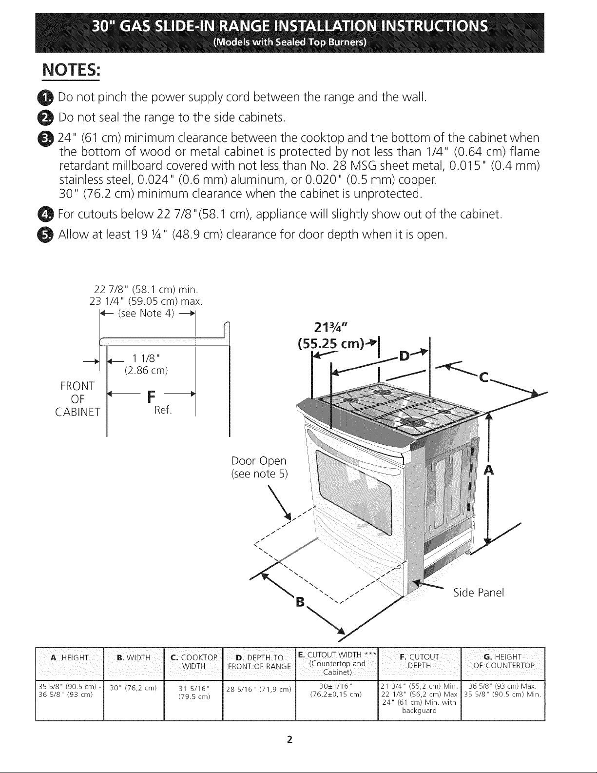
NOTES:
_!1 Do not pinch the power supply cord between the range and the wall.
Do not seal the range to the side cabinets.
_I 24" (61 cm) minimum clearance between the cooktop and the bottom of the cabinet when
the bottom of wood or metal cabinet is protected by not less than 1/4" (0.64 cm) flame
retardant millboard covered with not less than No. 28 MSG sheet metal, 0.01 5" (0.4 mm)
stainless steel, 0.024" (0.6 mm) aluminum, or 0.020" (0.5 mm) copper.
30" (76.2 cm) minimum clearance when the cabinet is unprotected.
For cutouts below 22 7/8"(58.1 cm), appliance will slightly show out of the cabinet.
q_! Allow at least 19 ¼" (48.9 cm) clearance for door depth when it is open.
22 7/8" (58.1 cm) min.
23 1/4" (59.05 cm) max.
(see Note 4)
'T..........
/
_/ _ 1 1/8
/ (2.86 cm)
FRONT /
II
CABINET
Door Open
(seenote 5)
A
\
i
/
/ /
i
-q.
Side Panel
A. HEIGHT B: wiDTH c] CoOKTOP D, DEPTH TO E. CUTOUT WIDTH F: CUToLIT G: HEIGHT
• . . Cabinet)
35 5/8" (90.5crn)- 30" (76,2 cm) 31 5/16" 28 5/16" (71,9 crn) 30el/16" 121 3/4" (55,2 cm) Min. 36 5/8" (93crn) Max.
36 5/8" (93 cm) (79.5 crn) (76,2e0,15 crn) 22 1/8" (56,2 cm) Max 35 5/8" (90.5crn) Min.
WDTH FRONTOF RANGE (Caunte_top and DEPTH OF COUNTERTOP
24" (61 cm) Min. with
backguard
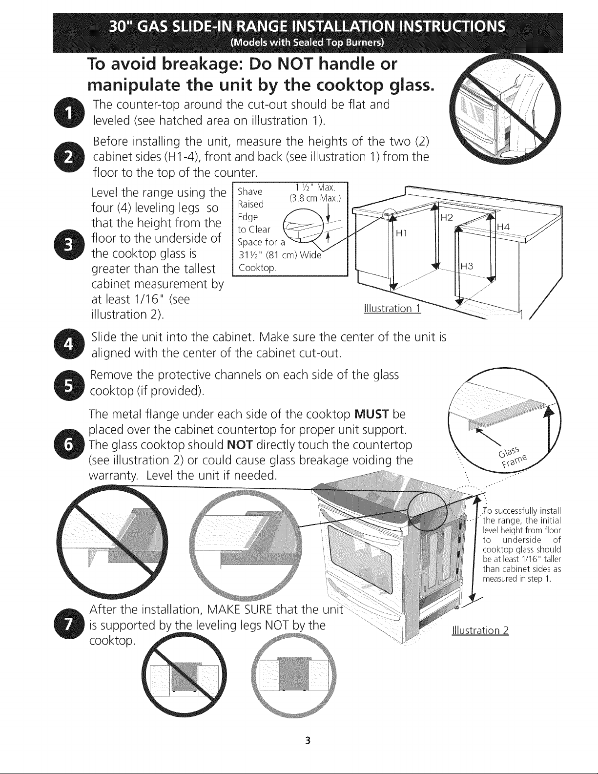
To avoid breakage: Do NOT handle or
manipulate the unit by the cooktop glass.
The counter-top around the cut-out should be flat and
leveled (see hatched area on illustration 1).
Before installing the unit, measure the heights of the two (2)
cabinet sides (H1-4), front and back (see illustration 1)from the
floor to the top of the counter.
Level the range using the
four (4)leveling legs so
that the height from the
floor to the underside of
the cooktop glass is
greater than the tallest
Shave
Raised
Edge
to Clear
Space for a
311/2" (81 cm)
Cooktop.
cabinet measurement by
at least 1/16" (see
illustration 2).
Slide the unit into the cabinet. Make sure the center of the unit is
1 1/2"Max. I
(3.8cm Max.)
I
Illustration 1
aligned with the center of the cabinet cut-out.
Remove the protective channels on each side of the glass
cooktop (if provided).
The metal flange under each side of the cooktop MUST be
placed over the cabinet countertop for proper unit support.
The glass cooktop should NOT directly touch the countertop
(see illustration 2) or could cause glass breakage voiding the
warranty. Level the unit if needed.
After the installation, MAKE SUREthat the
is supported by the leveling legs NOT by the
cooktop.
successfully install
the range, the initial
levelheight from floor
to underside of
cooktop glass should
be at least 1/16" taller
than cabinet sides as
measured in step 1.
Illustration 2
3
Important Notes to the Installer
1. Read all instructions contained in these installation
instructions before installing range.
2. Remove all packing material from the oven
compartments before connecting the gas and electrical
supply to the range.
3. Observe all governing codes and ordinances.
4. Be sure to leavethese instructions with the consumer.
5. Note: For operation at 2000 ft. elevations above see
level, appliance rating shall be reduced by 4 percent
for each additional 1000 ft.
Important Note to the Consumer
Keep these instructions with your Use & Care Guide for
future reference.
I RTANT SAFETY
shrinking, warping or discoloring. Do not install the
range over carpeting unless you place an insulating pad
or sheet of 1/4"(10,16 cm) thick plywood between the
range and carpeting.
o
Make sure the wall coverings around the range
can withstand the heat generated by the range.
o
Do not obstruct the flow of combustion air at the
oven vent nor around the base or beneath the
lower front panel of the range. Avoid touching the
vent openings or nearby surfaces as they may become
hot while the oven is in operation. This range requires
fresh air for proper burner combustion.
Never leave children alone or
unattended in the area where an appliance is in use.
As children grow, teach them the proper, safe use of all
appliances. Never leave the oven door open when the
range is unattended.
INSTRUCTIONS
Installation of this range must conform with local codes
or, in the absence of local codes, with the National Fuel
Gas Code ANSI Z223.1/NFPA .54-latest edition.
This range has been design certified by CSA
International. As with any appliance using gas and
generating heat, there are certain safety precautions you
should follow. You will find them in the Use and Care
Guide, read it carefully.
• Be sure your range is installed and grounded
properly by a qualified installer or service
technician.
This range must be electrically grounded in
accordance with local codes or, in their absence,
with the National Electrical Code ANSI/NFPA No.
70--latest edition. See Grounding Instructions.
Before installing the range in an area covered with
linoleum or any other synthetic floor covering,
make sure the floor covering can withstand heat at
least 90°F above room temperature without
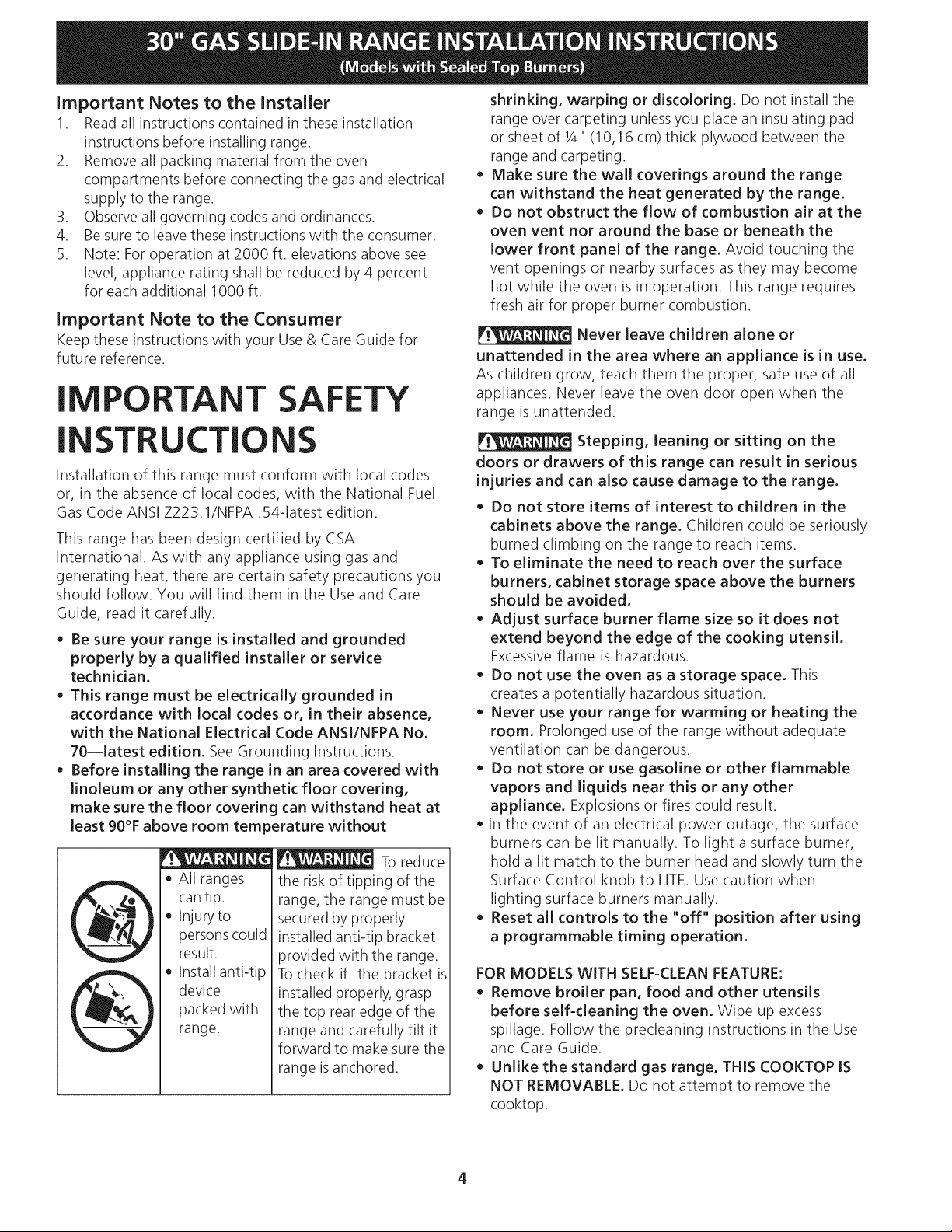
To reduce
All ranges
cantip.
Injury to
persons could
result.
Install anti-tip
device
packed with
range.
the risk of tipping of the
range, the range must be
secured by properly
installed anti-tip bracket
provided with the range.
To check if the bracket is
installed properly, grasp
the top rear edge of the
range and carefully tilt it
forward to make sure the
range is anchored.
Stepping, leaning or sitting on the
doors or drawers of this range can result in serious
injuries and can also cause damage to the range.
Do not store items of interest to children in the
cabinets above the range. Children could be seriously
burned climbing on the range to reach items.
To eliminate the need to reach over the surface
burners, cabinet storage space above the burners
should be avoided,
Adjust surface burner flame size so it does not
extend beyond the edge of the cooking utensil,
Excessiveflame is hazardous.
Do not use the oven as a storage space, This
creates a potentially hazardous situation.
Never use your range for warming or heating the
room, Prolonged use of the range without adequate
ventilation can be dangerous.
Do not store or use gasoline or other flammable
vapors and liquids near this or any other
appliance. Explosions or fires could result.
In the event of an electrical power outage, the surface
burners can be lit manually. To light a surface burner,
hold a lit match to the burner head and slowly turn the
Surface Control knob to LITE.Use caution when
lighting surface burners manually.
Reset all controls to the "off" position after using
a programmable timing operation.
FOR MODELS WITH SELF-CLEAN FEATURE:
Remove broiler pan, food and other utensils
before self-cleaning the oven. Wipe up excess
spillage. Follow the predeaning instructions in the Use
and Care Guide.
Unlike the standard gas range, THIS COOKTOP IS
NOT REMOVABLE, Do not attempt to remove the
cooktop.
4
Cabinet Construction
©
burns and fire, do not have cabinet storage space
above the range. If there is cabinet storage space
above range, reduce risk by installing a range
hood that projects horizontally a minimum of 5"
(12.7 cm) beyond the bottom of the cabinet.
Countertop Preparation
©
• The cooktop sides of the range fit over the
cutout edge of your countertop.
• If you have a square finish (flat) countertop,
no countertop preparation is required. Cooktop
sides lay directly on edge of countertop.
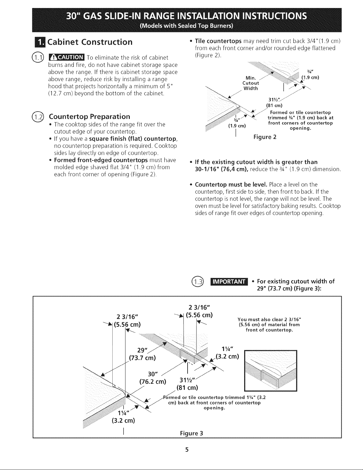
• Formed front-edged countertops must have
molded edge shaved flat 3/4" (1.9 cm) from
each front corner of opening (Figure 2).
To eliminate the risk of cabinet
• Tile countertops may need trim cut back 3/4"(1.9 cm)
from each front corner and/or rounded edge flattened
(Figure 2).
311/2"_
(81cm)
Formed or tile countertop
trimmed _A" (1.9 cm) back at
(1.9cm)
I
• If the existing cutout width is greater than
30-1116" (76,4 cm), reduce the s4" (1.9 cm) dimension.
Countertop must be level. Place a level on the
countertop, first side to side, then front to back. If the
countertop is not level, the range will not be level. The
oven must be level for satisfactory baking results. Cooktop
sidesof range fit over edges of countertop opening.
front corners of countertop
opening.
Figure 2
2 3116"
Figure 3
_ • For cutout width of
existing
29" (73.7 cm) (Figure 3):
Provide an adequate Gas Supply
When shipped from the factory, this unit is designed to
operate on 4"(10,16 cm) water column (1.0 kPa) Natural
gas manifold pressure. A convertible pressure regulator is
connected to the range manifold and MUST be
connected in series with the gas supply line. If LP/
Propane conversion kit has been used, follow instructions
provided with the kit for converting the pressure
regulator to LP/Propane use.
Care must be taken during installation of range not to
obstruct the flow of combustion and ventilation air.
For proper operation, the maximum inlet pressure to the
regulator should be no more than 14"(35,56 cm) of
water column pressure (3.5 kPa). The inlet pressure to
the regulator must be at least 1" (.25 kPa) greater than
the regulator manifold pressure setting. Examples: If
regulator is set for natural gas 4"(10,16 cm) manifold
pressure, inlet pressure must be at least 5"(12.60 cm); if
regulator has been converted for LP/Propane gas
10"(25,4 cm) manifold pressure, inlet pressure must be
at least 11 "(27,9 cm).
Leak testing of the appliance shall be conducted
according to the instructions in step 4.
The gas supply line should be 1/2"or 3A" I.D. (Interior
Diameter)
|Seal the openings
Seal any openings in the wall behind the range and in the
floor under the range after gas supply line isinstalled.
Connect the range to the gas supply
Important: Remove all packing material and literature
from range before connecting gas and electrical supply.
To prevent leaks, put pipe joint sealant on all external
pipe threads.
Your regulator is in location shown below.
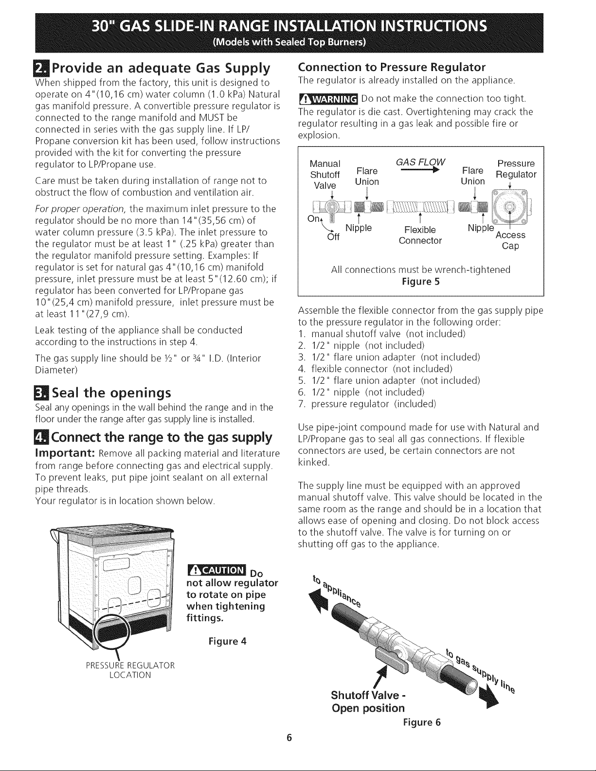
Connection to Pressure Regulator
The regulator is already installed on the appliance.
Do not make the connection too tight.
The regulator is die cast. Overtightening may crack the
regulator resulting in a gas leak and possible fire or
explosion.
Manual GAS FLOW Pressure
Shutoff Flare __ Flare Regulator
Valve Union Union ;
Nipple Flexible
Off Connector
All connections must be wrench-tightened
Figure 5
Assemble the flexible connector from the gas supply pipe
to the pressure regulator in the following order:
1. manual shutoff valve (not included)
2. 1/2" nipple (not included)
3. 1/2" flare union adapter (not included
4. flexible connector (not included)
5. 1/2" flare union adapter (not included
6. 1/2" nipple (not included)
7. pressure regulator (included)
Use pipe-joint compound made for use with Natural and
LP/Propane gas to seal all gas connections. If flexible
connectors are used, be certain connectors are not
kinked.
The supply line must be equipped with an approved
manual shutoff valve. This valve should be located in the
same room as the range and should be in a location that
allows ease of opening and closing. Do not block access
to the shutoff valve. The valve is for turning on or
shutting off gas to the appliance.
Nipple
Access
Cap
PRESSUREREGULATOR
LOCATION
Do
not allow regulator
to rotate on pipe
when tightening
fittings.
Figure 4
Shutoff Valve =
Open position
It%
Figure 6
Onceregulatorisinplace,opentheshutoffvalveinthe
gassupplyline.Waitafewminutesforgastomove
throughthegasline.
Checkfor leaks.Afterconnectingtherangetothegas
supply,checkthesystemforleakswithamanometer.If
amanometerisnotavailable,turnonthegassupplyand
usealiquidleakdetector(orsoapandwater)atall
jointsandconnectionstocheckforleaks.
Do not use a flame to check for leaks
from gas connections. Checking for leaks with a flame
may result in a fire or explosion.
Tighten all connections as necessary to prevent gas
leakage in the range or supply line.
Disconnect this range and its individual manual
shutoff valve from the gas supply piping system during
any pressure testing of that system at test pressures
greater than 1/2 psig (3.5 kPa or 14" water column).
Isolate the range from the gas supply piping system
by closing its individual manual shutoff valve during any
pressure testing of the gas supply piping system at test
pressures equal to or less than 1/2 psig (3.5 kPa or 14"
water column).
Electrical Requirements
120 volt, 60 Hertz, properly grounded dedicated circuit
protected by a 15 amp circuit breaker or time delay fuse.
Note: Not recommended to be installed with a Ground
Fault Interrupt (GFI).
Do not use an extension cord with this range.
Grounding Instructions
IMPORTANT Please read carefully.
For personal safety, this appliance must be properly
grounded.
The power cord of this appliance is equipped with a 3-
prong (grounding) plug which mates with a standard 3-
prong grounding wall receptacle (see Figure 7) to
minimize the possibility of electric shock hazard from the
appliance.
The wall receptacle and circuit should be checked by a
qualified electrician to make sure the receptacle is
properly grounded.
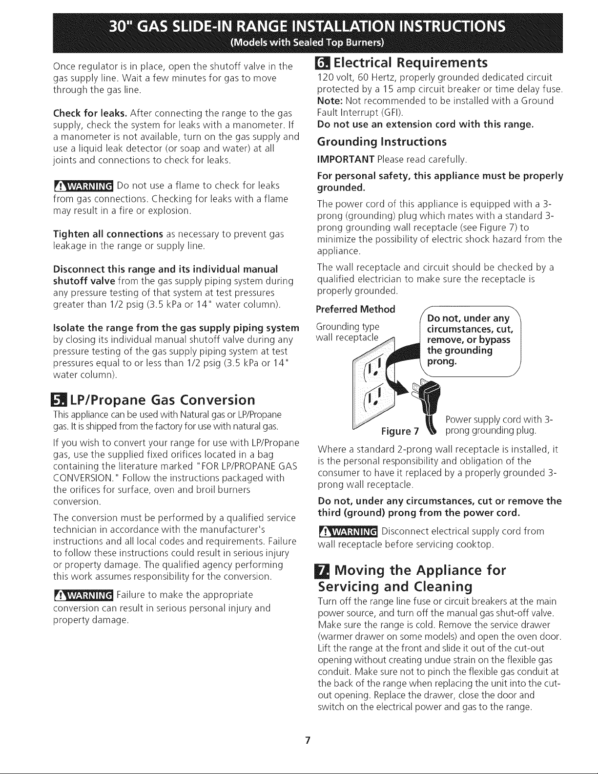
Preferred Method
Grounding type
wall receptacle
not, under any
circumstances, cut,
remove, or bypass
the grounding
prong.
LP/Propane Gas Conversion
Thisappliance can be usedwith Natural gas or LP/Propane
gas. It isshippedfrom the factory for usewith natural gas.
If you wish to convert your range for use with LP/Propane
gas, use the supplied fixed orifices located in a bag
containing the literature marked "FOR LP/PROPANEGAS
CONVERSION." Follow the instructions packaged with
the orifices for surface, oven and broil burners
conversion.
The conversion must be performed by a qualified service
technician in accordance with the manufacturer's
instructions and all local codes and requirements. Failure
to follow these instructions could result in serious injury
or property damage. The qualified agency performing
this work assumes responsibility for the conversion.
Failure to make the appropriate
conversion can result in serious personal injury and
property damage.
Power supply cord with 3-
Figure 7
Where a standard 2-prong wall receptacle is installed, it
is the personal responsibility and obligation of the
consumer to have it replaced by a properly grounded 3-
prong wall receptacle.
Do not, under any circumstances, cut or remove the
third (ground) prong from the power cord,
Disconnect electrical supply cord from
wall receptacle before servicing cooktop.
prong grounding plug.
Moving the Appliance for
Servicing and Cleaning
Turn off the range line fuse or circuit breakers at the main
power source, and turn off the manual gas shut-off valve.
Make sure the range is cold. Remove the service drawer
(warmer drawer on some models) and open the oven door.
Lift the range at the front and slide it out of the cut-out
opening without creating undue strain on the flexible gas
conduit. Make sure not to pinch the flexible gas conduit at
the back of the range when replacing the unit into the cut-
out opening. Replacethe drawer, dose the door and
switch on the electrical power and gas to the range.
7
Range Installation
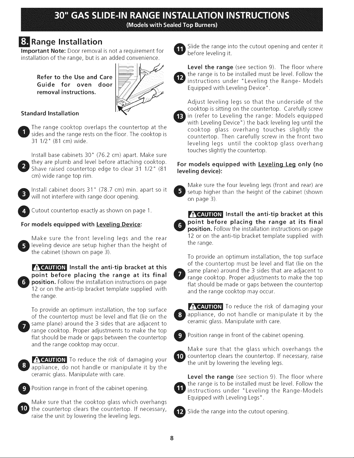
Important Note: Door removal is not a requirement for
installation of the range, but is an added convenience.
Refer to the Use and Care
Guide for oven door
removal instructions,
Standard Installation
The range cooktop overlaps the countertop at the
sides and the range rests on the floor. The cooktop is
31 1/2" (81 cm)wide.
Install base cabinets 30" (76.2 cm) apart. Make sure
they are plumb and level before attaching cooktop.
Shave raised countertop edge to clear 31 1/2" (81
cm) wide range top rim.
Install cabinet doors 31 " (78.7 cm) min. apart so it
will not interfere with range door opening.
Slide the range into the cutout opening and center it
before leveling it.
Level the range (see section 9). The floor where
the range is to be installed must be level. Follow the
instructions under "Leveling the Range- Models
Equipped with Leveling Device".
Adjust leveling legs so that the underside of the
cooktop is sitting on the countertop. Carefully screw
in (refer to Leveling the range: Models equipped
with Leveling Device") the back leveling leg until the
cooktop glass overhang touches slightly the
countertop. Then carefully screw in the front two
leveling legs until the cooktop glass overhang
touches slightly the countertop.
For models equipped with Leveling Leg only (no
leveling device):
Make sure the four leveling legs (front and rear) are
setup higher than the height of the cabinet (shown
on page 3).
Cutout countertop exactly as shown on page 1.
For models equipped with Leveling Device:
Make sure the front leveling legs and the rear
leveling device are setup higher than the height of
the cabinet (shown on page 3).
Install the anti=tip bracket at this
point before placing the range at its final
position. Follow the installation instructions on page
12 or on the anti-tip bracket template supplied with
the range.
To provide an optimum installation, the top surface
of the countertop must be level and flat (lie on the
same plane) around the 3 sides that are adjacent to
range cooktop. Proper adjustments to make the top
flat should be made or gaps between the countertop
and the range cooktop may occur.
To reduce the risk of damaging your
appliance, do not handle or manipulate it by the
ceramic glass. Manipulate with care.
Position range in front of the cabinet opening.
Make sure that the cooktop glass which overhangs
the countertop clears the countertop. If necessary,
raise the unit by lowering the leveling legs.
Install the anti=tip bracket at this
point before placing the range at its final
position. Follow the installation instructions on page
12 or on the anti-tip bracket template supplied with
the range.
To provide an optimum installation, the top surface
of the countertop must be level and flat (lie on the
same plane) around the 3 sides that are adjacent to
range cooktop. Proper adjustments to make the top
flat should be made or gaps between the countertop
and the range cooktop may occur.
To reduce the risk of damaging your
appliance, do not handle or manipulate it by the
ceramic glass. Manipulate with care.
Position range in front of the cabinet opening.
Make sure that the glass which overhangs the
countertop clears the countertop. If necessary, raise
the unit by lowering the leveling legs.
Level the range (see section 9). The floor where
the range is to be installed must be level. Follow the
instructions under "Leveling the Range-Models
Equipped with Leveling Legs".
Slide the range into the cutout opening.
If Accessories Needed :
Installation For 29" Existing Cutout Width Opening
1. You must replace the actual side trims by new and
smaller side trims. These new side panels can be
ordered through a Sears Service Center.
2. Follow instructions supplied with your new side trims
to replace the actual side trims with the new ones.
3. Check if the countertop is prepared for 29" cutout
wide opening at page 7.
4. Install range as in the "Installation Without Side
Panels" section above.
Installation With Backguard
A backguard kit can be ordered through a Sears Service
Center.The cutout depth (21 3/4" (55.2 cm) Min.,
22 1/8" (56.2 cm) Max.) needs to be increased to 24"
(61 cm) when installing a backguard
Installation With End Panel
An end panel kit can be ordered through a Sears
Service Center.
Installation With Side Panel
A side panels kit can be ordered through a Sears
Service Center.
Install cabinet doors 31 " (78.7 cm) min. apart so as not
to interfere with range door opening.
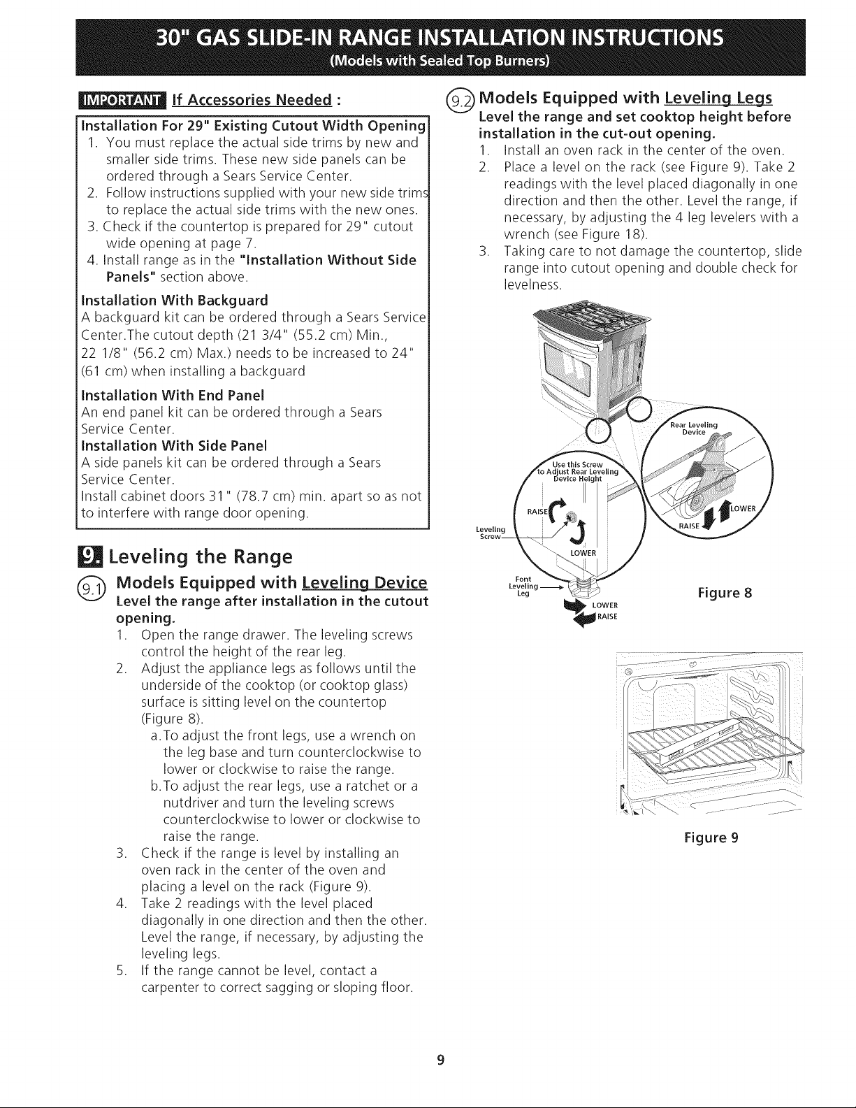
(9_ Models Equipped with Leveling Legs
Level the range and set cooktop height before
installation in the cut-out opening.
1. Install an oven rack in the center of the oven.
2. Place a level on the rack (see Figure 9). Take 2
readings with the level placed diagonally in one
direction and then the other. Level the range, if
necessary, by adjusting the 4 leg levelers with a
wrench (see Figure 18).
3. Taking care to not damage the countertop, slide
range into cutout opening and double check for
levelness.
Leveling the Range
(9._ Models Equipped with Leveling Device
Level the range after installation in the cutout
opening.
1. Open the range drawer. The leveling screws
control the height of the rear leg.
2. Adjust the appliance legs as follows until the
underside of the cooktop (or cooktop glass)
surface is sitting level on the countertop
(Figure 8).
a.To adjust the front legs, use a wrench on
the leg base and turn counterclockwise to
lower or clockwise to raise the range.
b.To adjust the rear legs, use a ratchet or a
nutdriver and turn the leveling screws
counterclockwise to lower or clockwise to
raise the range.
3. Check if the range is level by installing an
oven rack in the center of the oven and
placing a level on the rack (Figure 9).
4. Take 2 readings with the level placed
diagonally in one direction and then the other.
Level the range, if necessary, by adjusting the
leveling legs.
5. If the range cannot be level, contact a
carpenter to correct sagging or sloping floor.
Font
Leveling
Leg Figure 8
LOWER
RAISE
Figure 9
9
 Loading...