

Owners
Manual
FOR POTABLEWATER
HEATING ONLY
NOT SUITABLE FOR
SPACEHEATING
NOT FOR USE IN
MOBILE HOMES
Model No.
153.337113
153.337162
153.337213
153.337262
153.337362
153.337413
153.337462
153.337513
153.337562
153.337613
153.337662
153.337762
153.337862
153.337960
CauUon:
Read and Follow
All Safety Rules and
Operating Instructions
Before First Use of
This Product.
50 Gal. Short High Altitude
50 Gal. Short
40 Gal. Short High Altitude,
40 Gal. Short
30 Gal.
40 Gal. High Altitude
40 Gal.
50 Gal. High Altitude
50 Gal.
65 Gal, High Altitude
65 Gal.
50 Gal. High Recovery
65 Gal. High Recovery
40 Ga!.(LP.)
POWER MISERTM9
GAS WATER H EATER
• Safety Instructions • Care and Maintenance
• Installation • Troubleshooting
• Operation • Parts List
For Your Safety
AN ODORANT IS ADDED TO THE GAS USED BY THIS
WATER HEATER
WARNING: If the information in these instructions are not fol-
lowed exactly, a .fire or explosion may result, causing property
damage, personal ,nlury or death.
-Do not store or use gasoline or other flammable vapors and liq-
uids in the vicinity of t_is or any other appliance.
-WHAT TO DO IF YOU SMELL GAS
Do not try to light any appliance.
Do not touch any electr,'cal switch; do not use any phone in your
building. . .
Immediately call your I_as supp.her from a ne,ghbor's phone.
i Follow gas suppliers instructions.
If you can not reach your gassuppl,er, call the fire department.
-Installation and service must be performed by a qualified installer,
service agency or the gas supplier.
Improper installatmn, adlus_on , service or maintenance I
can cause DEATH, SERIOUS BODILY INJURY, OR PROPERTY DAM- I
AGE. Refer to this manual for assistance or consult the local Sears I
Service Center or gas utility for further reformation. J
the
AWARNING
• .
]
Savethis Manual for Future Reference.
Sears, Roebuck and Co., Hoffman Estates, IL 60179 U.S.A.
Flammable vapors may be drawn by air currents from other areas
of the structure to this appliance.
&WARNING t
AWARNING
READ THE GENERAL SAFETY SECTION BEGINNING ON INSIDE
COVER AND THEN THIS ENTIRE MANUAL BEFORE INSTALLING
OR OPERATING THIS WATER HEATER•
Safety Precautions
AWARNING
Improper installation, adjustment, alteration, service or I
maintenance can cause DEATH, SERIOUS BODILY
INJURY, OR PROPERTY DAMAGE. Refer to this manu-
al for assistance or consult your local Sears Service
Center for further information. I
AWARNING
WATER HEATERS EQUIPPED FOR ONE TYPE GAS
ONLY: This water heater is equipped for one type gas
only. Check the model rating plate near the gas control
valve for the correct gas. DO NOT USE THIS WATER
HEATER WITH ANY GAS OTHER THAN THE ONE
SHOWN ON THE MODEL RATING PLATE. Failure to
usethe €orrect gascan cause problems which can result in
DEATH, SERIOUS BODILY INJURY, OR PROPERTY
DAMAGE. If you have any questions or doubts consult
your gassupplier or local utility.
4WARNING
INSTALLATIONS IN AREAS WHERE FLAMMABLE LIQ-
UIDS (VAPORS) ARE LIKELY TO BE PRESENT OR
STORED (GARAGES, STORAGE, AHD UTILITY AREAS,
ETC): Flammable liquids (such as gasoline, solvents,
propane (LP) or butane, etc.), all of which emit flammable
vapors, may be improperly stored or used in such areas.
The gas water heater pilot tightor main burner can ignite
such vapors. The resulting flashback and fire can cause
death or serious burns to anyone in the area, _ well as
property d_magn, i
If installation in such areas isyour only option, then the
installation must be accomplished in a way that the pilot
flame and main burner flame are elevated from the floor
at least 18 inches. While this may reduce the chancesof
!flammable vapors from a floor spill being ignited, gasoline
iand other flammable substancesshould never be stored or
used in the same room or erda containing a gas water
heater or other open flame or spark producingappliance.
NOTE: Flammable vapors may be drawn by air currents
from other areas of the structure to the appliance.
AWARNING
If this water heater will be used in beauty shops, barber
shops, cleaning establishments, or self-service laundries
with dry cleaning equipment, it is imperative that the
water heater or water heaters be installed so that €om-
bustion and ventilation air be taken from outside these
areas, Refer to the "Facts to Consider About the
Location" section of this manual and also the latest edi-
tion of the National Fuel Gas Code, ANSI Z223.1, also
referred to as NFPA 54 for specifics provided concernin
air required,
I A WARNING . I
A fire can start if combustible materials such as cloth,ng,
cleaning ma_, or flamm_de liquids are placed againstI
or next to the water heater. [
AWARNING
At the time of manufacture this water heater was provid-
ed with a combination temperature-pressures relief valve
certified by a nationally recognized testing laboratory
that maintains periodic inspection of production of listed
equipment or materials, as meeting the requirements
for Relief Valves and Automatvc Gas Shutoff Devices for
Hot Water Supply Systems, and the latest edition of
ANSI Z21.22 and the code requirements of ASHE. If
replaced, the valve must meat the requirements of local
codes, but not lessthan a combination temperature and
pressure relief valve certified as meeting the require-
ments for Relief Valves and Automatic Gas Shutoff
Devices for Hot Water Supply Systems, ANSI Z21.22 by
a nationally recognized testing laboratory that maintains
periodic inspection of production of listed equipment or
materials.
The valve must be marked with a maximum set pressure
not to exceed the marked hydrostatic working pressure
of the water heater (I 50 IbsJsq. in.) and a discharge
capacity not less than the water heater input rate as
shown on the model rating plate. (Electric heaters -
watts divided by 1000 x 3415 equal BTU/Hr. rate.)
[Your local jurisdictional authority, while mandating the
use of a temperature-pressora relief valve complying
with ANSI Z21.22 and ASME, may require a valve model
different from the one furnished with the water heater.
Compliance with such local requirements must be satis-
fied by the installer or end user of the water heater with
a locally prescribed temperature-pressure relief valve
installed in the designated opening in the water heater in
place of the factory furnishedvalve.
For safe operation of the water heater, the relief valve
must not be removed from it's designated opening or
plugged.
Tho temperatere-pressore relief valve must be installed
directly into the fitting of the water heater designated
for the relief valve. Position the valve downwlu_l and pro-
vide tubing so that any discharge will exit only within 6 i
inches above, or at any distance below the structural
floor. Be certain that no contact is made with any live
electrical part. The discharge opening must not be
blocked or reduced in size under any circumstances.
Excessivelength, over 30 feet, or use of more than four
elbows can cause restriction and reduce the discharge
capacity ofthe valve.
No valve or other ebstxuction is to be placed between
the relief valve and the tank. Do not connect tubing
ditec_ to discharge drain unlessa 6" air gap isprovided.
To prevent bodily injury, hazard to life, or property dam-
age, tho relief valve must be allowed to discharge water
in quantities should circumstances demand. If the dis-
charge pipe is not connected to a drain or other suitable
means, the water flow may cause property damage.
The Discharge Pipe:
• Must not be smaller in size than the outlet pipe size of
the valve, or have any reduclng couplings or other
restrictions.
Must not be plugged or blocked.
Must be of"material listed fur hot water distribution.
Must be installed so as to allow complete drainage of
both the temperature-pressure relief valve, and the
dischargel_e,
Must terminate at an adequate drain,
Host not have any valve between the relief valve and
tank.
Safety Precautions
_,WARNING
A gaswater heater cannot operate properly without the
correct amount of air for combustion. Do not install in a
confined area such a closet, unless you provide air as
shown inthe "Facts to Consider About the Location" sec-
tion. Never obstruct the flow ofventilation air. If you have
any doubts or questions at all, call your gas company.
Failure to provide the proper amount of combustion air
can result in a fire or explosion and can CAUSE DEATH,
SERIOUS BODILY INJURY,OR PROPERTY DAMAGE.
AWARNING
HOTTER WATER CAN SCALD: Water heaters are
intended to produce hot water. Water heated to a tern-
perature which willsa_ clotheswashing, disk washing,
and other sanitizing needs can scald and permanently
injure you upon €ontac_ Some people ace more likely to
be permanently injured by hot water than other_ These
include the elderly,children, the infiPm,or physicailyimen-
tally handicapped.If anyone usinghot water in your home
fits into one of these groupsor if there Is a local code or
state Ilw requiring a certain temperature water at the hot
water tap, then you must take specialprecautions, In addi-
tion to usingthe lowest possible temperature setting that i
satisfiesyour hot water needs, a means suchas a mixing I
valve, shouldbe used at the hot water tapsused by these
people or at the water heater. Mixing valvesare available
at plumbing supply or hardware stores. Follow manufac-
turers instructions for installation of the valves. Before
changingthe fa_)ry setting on the thermostat, read the
'_l'emperature Regulation" sectionin this manual.
A,WARNING
Soot build-up Indicates a problem that requires correc-
tion before further use, Turn "OFF" gas to water heater
and leave "OFF" until repairs are made, because failure
to correct the causeof the sooting can result in s fire or
Iexplosion causing DEATH, SERIOUS BODILY INJURY,
OR PROPERTY DAMAGE.
_WARNING
This water heater must not be installed directly on car-
Feting. Cerpe_ag must be protected by a metal or wood
panel beneath the appliance extending beyond the full
width and depth of the appliance by at least 3 inches
(76.2mm) in any direction, or iftbe appliance is installed
in analcove or c oset, the entire floor must be coveredby
the panel. Failure to heed this warning may result in a
Ere hazard.
AWARNING
VENT DAMPERS - Any vent damper, whether it is operat-
ed thermally or otherwise must be removed if Its use
inhibitsproper drafting of the water heater.
Thermally Operated Vent Dampers: Gas-fired water
heaters having thermal efficiency in excess of 80% may
*roduce a relatively low flue gastemperature. Such tem-
peratures may not be high enough to properly open ther-
mally operated vent dampers. This would causespillageof
flue gasesand may causecarbon monoxide poisoning.
Vent dampers must bear evidence of certification ascom-
plying with the latest edition of American National
Standard ANSI Z21.68(ANSI Z21.66 & 67, respectively,
cover electrically and mechanically actuated vent
I
dampers). Before installation of any vent damper, consult
your local Sears Service Center or the gas utility for fur-
ther nformat on.
AWARNING
•The appliance and its Individual shutoff valve must be dis.
connected from the gall supply piping systemduring any
pressure testing of the gas system at test pressures In
excessof '/2pound per square inch (3.$kPa).
•The appliancemust be isolatedfrom the gassupplypip-
ing system by closing its individual manual shutoffvalve
during any pressuretesting of the gas supply pipingsys-
tem at test pressures equal or lessthan '/2pound per
square Inch (3.SkPa).
_,WARNING
BEFORE LIGHTING [PROPANE (L.P.) GAS WATER
HEATERS): Propane (L.R) gas is heavier than air. Should
there be a leak In the system, the gas will settle near the
ground. Basements, crawl spaces, skirted areas under
mobile homes (even when ventilated), closets and areas
below ground levelwill serve as pockets fur the accumula-
tion of this gas. Before attempting to light or relight the
water heater's pilot or turning on a nearby electrical light
switch, be absolutely sure there is no accumulated gas In
the aceL Search for odor of gasby sniffingat ground level
in the vicinity of the appliance. If odor is detected, follow
steps indicated at "For Your Safety" on the cover page of
this manualthen leavethe premises.
AWARNING
Chemical vapor corrosion of the flue and vent system
may occur if air fur combustion contains certain chemical
vapors.Spraycan propellants, cleaning solvents,refrigera-
tor and air conditioner refrigerants, swimming pool
chemicals, calcium and sodium chloride, waxes, bleach,
and process chemicals are typical compounds which are
potentially corrosive.
I _,WARNING
Obstructedor deterioratedvent systems maypresenta
serioushealthriskor asphyxiation.
Safety Precautions continuedon page4.
3
Safety Precautions
I A,WARNING J
The water heater with draft hood installed must be prop-[
erly vented to a chimney which terminates outdoors.]
Never operate the water heater unlessit is vented to the]
outdoors and has adequate air supply to avoid risks of[
Improper operation, explosionor asphyxiation. [
AWARNING
Minimum clearancesbetween the water heater end com-
bustiblecon_ction am I" at the sidesand rear, 4" at the
front, and 6 from the vent pipe. Clearence from the top
of the jacket is 18" on most models. Note that a lesser
dimension may be allowed on some models. Refer to the
label on the water heater adjacent to the gascontrol valve
for all clearances.
I &WARNING I
Do not use this _opllence if any part of It hasbeen under I
water, immediately call a Sears Service Technician to I
inspect the appliance andto replace the gas control or any J
part of the burner system which hasbeen under water. I
&WARNING
HYDROGEN GAS: Hydrogengas canbe producedIn a hot
water system that hasnot been used for a long period of
time (generally two weeks or more). Hydrogen gas is
exVemelyfl_mma_e _d mq_s_e. Topreventthe pem-
bility of injury under these conditions, we recommend the
hot water faucet be opened for several minutes at the
kitchen sink before any electrical appliances which
connected to the hot water system are used (suchas a dis-
hwasher or washingmachine). If hydrogen gasis present,
there will probably be an unusual sound similar to air
escaping through the pipe as the hot water faucet Is
opened. There must be no smoklnfl or open R_umenear
the faucetat the time It is open.
ACAUTION
WATER HEATERS EVENTUALLY LEAK: Installation of
t_ water heater must be accomplishedin such a manner
that Iftho tank or any connectionsshouldleak, the flow of
water will not causedamage to the structure. When such
locations cannot be avoided, a suitable drain pan should
be instal ed under the water heater. Drain pans are wall.
at ynor load Sun s_re. Such a drain pan must be
not greater than 1½ Inchesdeep, havea minimum length
and width of at least 2 Inches greater than the water
heater dimensions and must be piped to an adequate
drain. The pan must not restrict combustion air flow,
Under no clrcumstencesis the manufectumr or Sears to
be held liable for any water damage in connection with
this water heater.
AWARNING
INSULATING JACKETS: When installing an external
water heater insulationjacket on a p.s water heater:
• DO NOT cover the temperature-pressure relief valve.
• DO NOT put Insulation over any part of the top of the
gaswater heater.
• DO NOT put insulation overthe gascontrol wive or gas
control valve/burner coverpor any accessareas to the
burner.
• DO NOT let insulation around the gaswater heater to
get within 8 inches of the floor (air must get to the
burner).
• DO NOT cover or remove operating Instructions. and
safety related warning labels and materials affixedto tee
water heater.
Failure to heedthis will result In the pesslbility of a fire or
explosion.
4
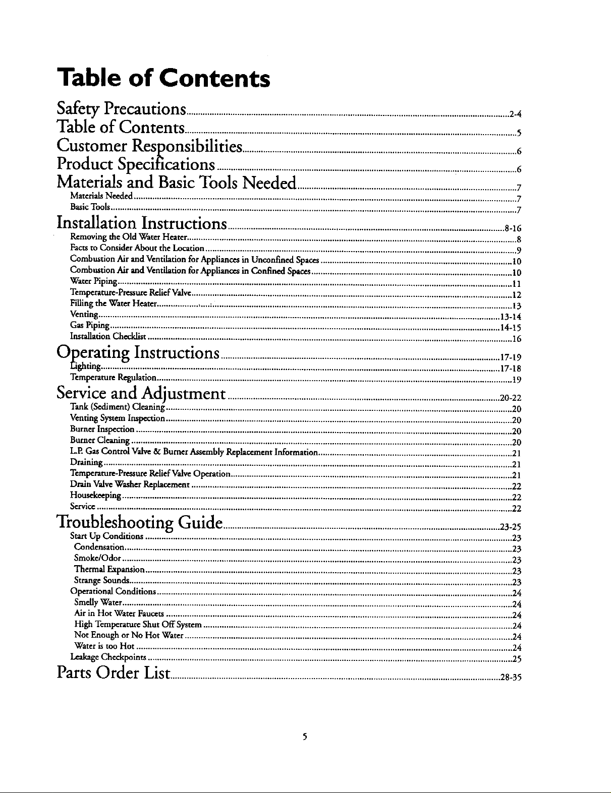
Table of Contents
Safety Precautions ............................................................................................................................................2_
Table of Contents ................................................................................................................................................5
Customer
Product
T'_ ol_14e
Kesponslbllltles .......................................................................................................................6
_ o/,b .
_pecmcauons ..................................................................................................................................6
Materials and Basic Tools Needed ....................................................................i..........................7
Materials Needed ...................................................................................................................................................................... 7
Basic Tools ................................................................................................................................................................................ 7
Installation Instructions ........................................................................................................................8-16
Removing the Old Water Heater ............................................................................................................................................... 8
Facts to Consider About the Location ....................................................................................................................................... 9
Combustion Air and Ventilation for Appliances in Unconfined Spaces ................................................................................... 10
Combustion Air and Ventilation for Appliances in Confined Spaces ....................................................................................... 10
Water Piping ........................................................................................................................................................................... 11
Temperature-Pressure Relief Valve ........................................................................................................................................... 12
Filling the Water Heater ....................... ;.................................................................................................................................. 13
Venting .............................................................................................................................................................................. 13-14
Gas Piping ......................................................................................................................................................................... 14-15
Installation Checklist .............................................................................................................................................................. 16
_""t)peratmgInstructions .........................................................................................................................17-19
Eighting .........Z. ................................................................................................................................................................ 17-18
Temperature Regulation .......................................................................................................................................................... 19
Serviceand
Tank (Sediment) Cleaning_....................................................................................................................... 20
Venting System Inspection ...................................................................................................................................................... 20
Burner Inspection ................................................................................................................................................................... 20
Burner Cleaning ..................................................................................................................................................................... 20
L.E Gas Control Valve & Burner Assembly Replacement Information .................................................................................... 21
Draining ................................................................................................................................................................................. 21
Temperature-Pressure Relief Valve Operat on .............................................................................. 21
Drain Valve Washer Replacement ........................................................................................................................................... 22
Housekeeping ......................................................................................................................................................................... 22
Service .................................................................................................................................................................................... 22
ACtlustment ......................................................................................................................20-22
"_ -" -"lroubleshootlng Guide ........................................................................................................................23-25
Start Up Conditions ...............................................................................................................................................................v 23
Condensation ........................................................................................................................................................................ 23
Smoke/Odor ......................................................................................................................................................................... 23
Thermal Expansion ............................................................................................................................................................... 23
Strange Sounds ...................................................................................................................................................................... 23
Operational Conditions .......................................................................................................................................................... 24
Smelly Water ......................................................................................................................................................................... 24
Air in Hot Water Faucets ...................................................................................................................................................... 24
High Temperature Shut Off System ...................................................................................................................................... 24
Not Enough or No Hot Water .............................................................................................................................................. 24
Water is too Hot ................................................................................................................................................................... 24
Leakage Checkpoints .............................................................................................................................................................. 25
Parts Order List...............................................................................................................................................28-35
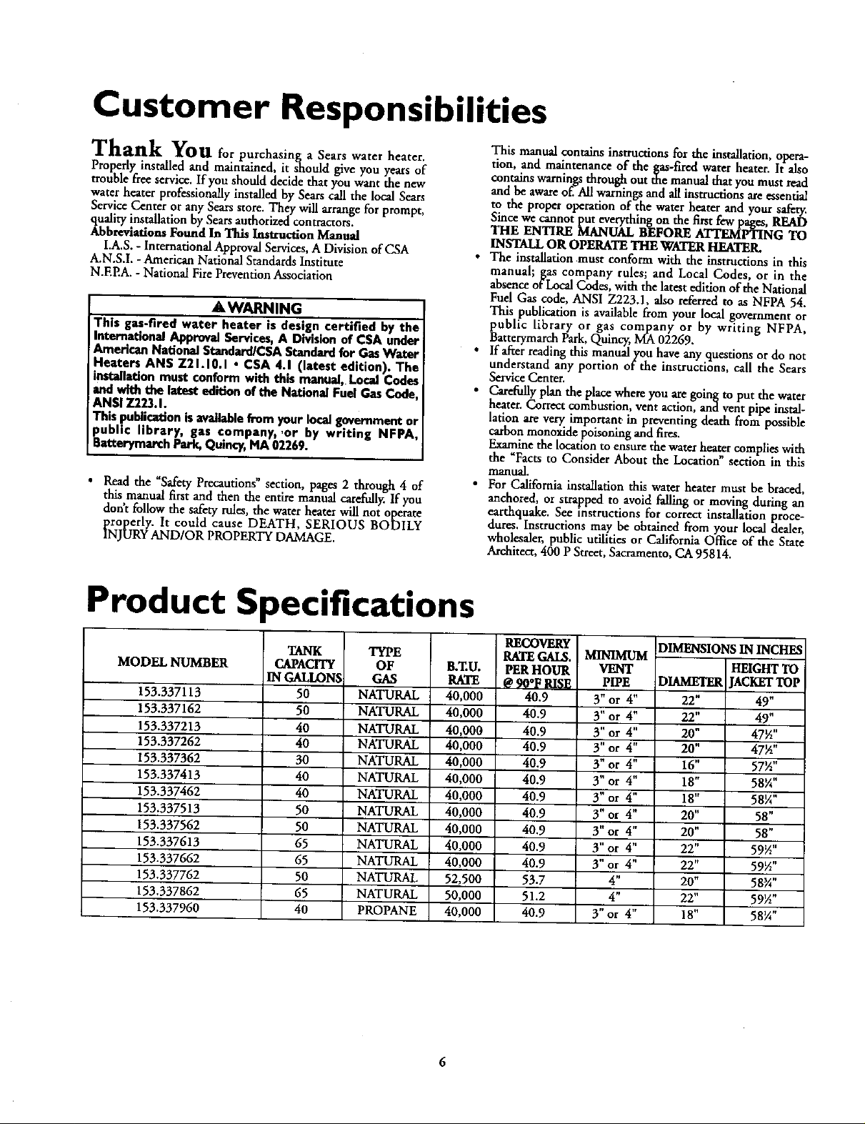
Customer Responsibilities
Thank You _or purchasinga Sears water heater.
Properly installed and maintained, it should give you years of
trouble free service. If you should decide that you want the new
water heater professionally installed by Sears call the local Sears
Service Center or any Sears store. They will arrange for prompt,
quality installation by Sears authorized contractors.
Abbreviations Found In This Instruction Manual
I.A,S. - International Approval Services, A Division of CSA
A.N.S.I, - American National Standards Institute
N.EEA. - National FirePrevention Association
AWARNING
This gas-fired water heater is design certified by the
International Approval Services, A Division of CSA under
American National Standard/C$A Standard for Gas Water
Heaters AN$ Z21.10.1 • CSA 4.1 (latest edition). The
installation must conform with this manual, Local Codes
and with the latest edition of the National Fuel Gas Code,
ANSI Z223.1.
This publication is available from y_ur local government or
public library, gas company, or by writing NFPA.
Batterymarch Park, Quincy, MA 02269.
• Read the _Safety Precautions" section, pages 2 through 4 of
this,manual first and then the entire manual carefiflly. If you
dont follow the safety rules, the water heater will not operate
properly. It could cause DEATH, SERIOUS BODILY
INJURY AND/OR PROPERTY DAMAGE.
This manual contains instructions for the installation,opera-
tion, and maintenance of the gas-fired water heater. It also
contains warningsthrough out the manual that youmust read
and be awareoffAll warnings andall instructionsareessential
to the proper operation of the water heater and your safety.
Sincewe cannot put everythingon the first few pages,READ
THE ENTIRE MANUAL BEFORE ATTEMPTING TO
INSTALLOR OPERATETHEWATERHEATER.
• The installation must conform with the instructions in this
manual; gas company rules; and Local Codes, or in the
absenceofLocalCodes,with the latestedition ofthe National
FuelGas code, ANSI Z223.1, also referredto as NFPA 54.
This publication is available from your local governmentor
public library or gas company or by writing NFPA,
BattcrymarchPark,Quincy,MA02269.
• If a_er reading this manualyou haveany questions ordo not
understand any portion of the instructions, call the Sears
ServiceCenter.
• _y plan the placewhere you are going to put the water
heater. Correct combustion, vent action, and ventpipe instal-
htion are very importan_ in preventing dear from possible
cathon monoxidepoisoningand fires.
Examinethe locationto ensure the water heatercomplies with
the _Facrsto Consider About the Location"section in this
manual.
• For California installation this water heater must be braced,
anchored, or strapped to avoid failing or moving during an
earthquake. See instructionsfor correct installation proce-
dures.Instructions may be obtained from your local dealer,
wholesaler,public utilities or California Office of the State
Architect,400 P Street,Sacramento, CA 95814.
Product Specifications
MODEL NUMBER
153.337113
153.337162
153.337213
153.337262
153.337362
153.337413
153.337462
153.337513
153.337562
153.337613
153.337662
153.337762
153.337862
153.337960
TANK
CAPACITY
IN GALLONS
50
50
40
40
30
40
40
50
50
65
65
50
65
40
TYPE
OF
GAS
NATURAL
NATURAL
NATURAL
NATURAL
NATURAL
NATURAL
NATURAL
NATURAL
NATURAL
NATURAL
NATURAL
NATURAL
NATURAL
PROPANE
B,ZU.
RATE
40,000
40,000
40,000
40,000
40,000
40,000
40,000
40,000
40,000
40.000
40,000
52,500
50,000
40,000
RECOVEI_
RATE GAI&
PER HOUR
@9O°F8II;!_
40.9
40.9
40.9
40.9
40.9
40.9
40.9
40.9
40.9
40.9
40.9
53.7
51.2
40.9
MINIMUM
VENT
PIPE
3" or 4"
3"or 4"
3" or 4"
3"or 4"
3" or 4"
3" or 4"
3" or 4"
3" or 4"
3" or 4"
3"or 4"
3"or 4"
4"
4"
3"or 4"
DIMENSIONSIN INCHES
HEIGHTTO
)IAMETER JACKETTOP
22" 49"
22" 49"
20" 47½"
20" 47½"
16" 57½"
18" 58_A"
lg" 5glA"
20" 58"
20" 58"
22" 59½"
22" 59½"
20" 58_A"
22" 59½"
18" 58¼"

Materials and Basic Tools Needed
Materials Needed
To simplify the installation Sears has available the installation
_lsartsshown below.Youmay ormaynot needall of thesemateri-
, depending-onyour type of installation.
WATER HEATER HEAT
TRAPS HELP REDUCE
NEAT LOSS DUE TO
THERMAL SYPHONING
EXPANSION TANKS
FOR THERMAL
EXPANSION CONDI-
TIONS AVAILABLE IN
2 GALLON AND $
GALLON CAPACITY
THROUGN LOCAL
SEARS STORE OR
SERVICE CENTERS
VENT PIPE
WATER NEATER INSTAL-
LATION KIT WITH FLEXI-
BLE CONNECTORS FOR
314" OR 112" THREADED
OR COPPER PLUMBING
@
VENT ELBOW
FLEXIBLE WATER
HEATER GAS CON-
HECTOR WITN
FITTINGS
/ \
WATER HEATER STAND 24"x24"xl 8"
FOR USE WITH WATER HEATERS
INSTALLED IN RESIDENTIAL
GARAGES HAVING A DIAMETER 24"
OR LESS AND A RATED CAPACITY 7S
GALLONS OR LESS
DRAIN PANS AVAILABLE IN 20"
DIAMETER FOR WATER HEATERS
HAVING A DIAMETER 18" OR LESS
AND AVAILABLE IN 28" DIAMETER
FOR WATER HEATERS HAVING A
DIAMETER 26" OR LESS
Basic Tools
You may or may not need all of these tools, depending on your
type of installation. These tools can be purchased at your local
Scrags store,
• Pipe Wrenches (2) 14"
• Screwdriver
• Tin Snips
• 6 Foot Tape of Folding Rule
• Garden Hose
• Drill
• Pipe dope or Teflon Tape
GARDEN HOSE 6 FOOT TAPE
SLOT-HEAD SCREWDRIVER
PHILLIPS SCREWDRIVER
ROLL OF TEFLON TAPE
(USE ONLY ON WATER
CONNECTIONS)
PIPE DOPE (SQUEEZE TUBE)
USE FOR WATER AND
_AS CONNECTIONS)
PiPE
WRENCH
TIN SNIPS
ADDITIONAL TOOLS NEEDED
WHEN SWEAT SOLDERING
• Tubing Cutters or Hacksaw
• Propane Torch
• Sof_ Solder
• Solder Flux
• Emery Cloth
• Wire Brushes
HACKSAW
$14" WIRE BRUSH
C>--'"
ROLL OF LEAD FREE
ROLL OF EMERY
I/2" WIRE BRUSH
PROPANE
TORCH
SOFT SOLDER
CLOTH SOLDER FLUX TUBING
CUTTER
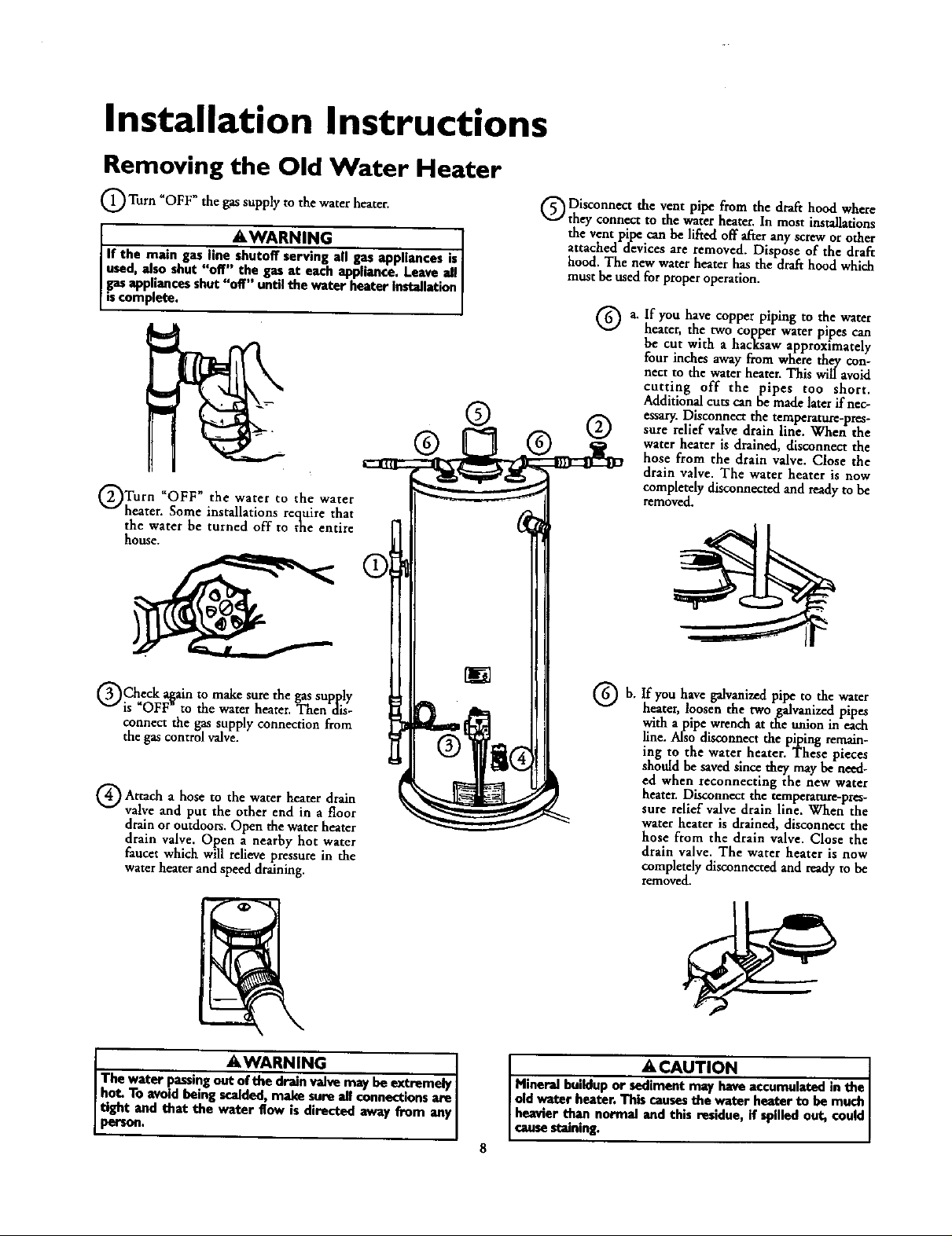
Installation Instructions
Removing the Old Water Heater
_OFF"the the heater,
Turn gassupply to water
l AWARN,N I
If the main gasline--all gasappliancesis
used, _lso shut'doff'"the gasat eachappliance. Leaveall
gasappliancesshut"off'" untilthe waterheaterinstallation
iscomplete.
@@ @ @
Turn _OFF" the water to the water
heater. Some installations require that
the water be turned off to the entire
house.
Disconnect the vent pipe from the drafthood where
they connect to the waterhearer.In most installations
the ventpipe canbe lifted off afterany screworother
attached devicesare removed, Dispose of the draft
hood. The new water heater has the drafthood which
mustbe usedfor properoperation.
a. If you have copper piping to the water
heater, the two copper water pipes can
be cut with a hacksaw approximately
four inches awayfrom where they con-
nect to the water heater. This will avoid
cutting off the pipes too short.
Additionalcuts can bemadelaterif nec-
essary.Disconnectthe temperature-pres-
sure relief valvedrainline. When the
water heater is drained,disconnect the
hose from the drain valve. Close the
drain valve. The water heater is now
completelydisconnectedandreadyto be
removed.
Check a_ainto make sure thegassupply
is OFF to the water heater. Then dis-
connect the gassupply connection from
the gascontrol valve.
a to water
Attach hose the heater drain
valve and put the other end in a floor
drainoroutdoors.Open the waterheater
drain valve. Open a nearby hot water
faucet which willrelievepressure in the
waterheater and speed draining.
I AWARNING
The water passingout--valve may be extremely
hot. To avoid being scalded,make sure all connectionsare I
i_.d that the water flow is directed away from any I
If you have galvanized pipe to the water
b,
heater, loosen the two galvanized pipes
with a pipe wrench at the anion in each
line. Also disconnect the piping remain-
lug to the water heater. These pieces
should be saved since they may be need-
ed when reconnecting the new water
heater. Disconnect the temperature-pres-
sure relief valve drain llne. When the
water heater is drained, disconnect the
hose from the drain valve. Close the
drain valve, The water heater is now
completely disconnected and ready to be
removed.
ACAUTION I
Mineral buildup or sediment may have accumulated in the
old water heater. Thiscausesthe water heater to be much
heavier than normal and this residue, if spilledout, could
causestaining.
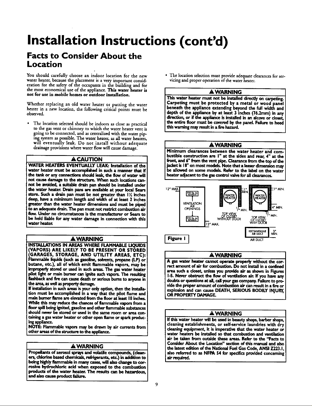
Installation Instructions (cont'd)
Facts to Consider About the
Location
You should carefully choose an indoor location for the new
water heater, because the placement is a very important consid-
eration for the safety of the occupants in the building and for
the most economical use of the appliance. This water heater is
not for use in mobile homes or outdoor installation.
Whether replacing an old water heater or putting the water
heater in a new location, the following critical points must be
observed.
• The location selected should be indoors as close as practical
to the gas vent or chimney to which the water heater vent is
going to be connected, and as centralized with the water pip-
in._ system as possible. The water heater, as all water heaters
will eventually leak. Do not install without adequate
drainage provisions where water flow will cause damage.
&CAUTION
WATER HEATERS EVENTUALLY LEAK: Installation of the
water heater must be accomplisbedin sucha manner that if
the tank or anyconnectionsshouldleak,the flowof water will
notcausedan_ge to the structure.Wben suchIocatfonscan-
not be avoided, a soitalde drain panshouldbe installedunder
the water buater. Drain pansm_eavailableat your local Sears
store. Such a drain pan must be lootgreater than I _ inches
deep, have a minimum lengthand width of at least 2 inches
greater than the water heater dimensionsand must be piped
ito anadequatedrain.The panmust notrestrict combustionair
iBow.Under no circumstancesis the manufactureror Searsto
! be held liablefor any water damage in connectionwith this
!water heater.
• The location selection must provide adequate clearances for ser-
vicing and proper operation of the waterheater.
AWARNING
This water heater must loot be installeddin_y on carpeting.
Carpeting must be protected by a metal or wood panel
beneath the appliance extending beyond the full width and
depth of the appliance by at least 3 inches (76.2mm) in any
direction,or if the applianceis installedin an alcoveor deset,
the entire floormust be coveredby the panel.Failureto heed
this warningmayresultin a firehazard.
AWARNING
Minimum clearances between the water heater and com-
bustibleconstruction are I" at the sidesand rear, 4" at the
front,and6" frem the vant pipe.Clearancefrom the top of the
jacketis I8" onmostmodelg Note that a lesserdimensionmay
be allowedon some modelg Refer to the labelon the water
heater adjacantto the gascnotrelvaivefor all dearance_
12"M__
VENTILATION
TOPP V_E'V,/
OF CLOSET TOP VI_
WITHOUT DOOR V_OIFT_ _d_
AWARNING
INSTALLATIONS IN AREAS WHERE FLAMMABLE LIQUIDS
VAPORS) ARE LIKELY TO BE PRESENT OR STORED
GARAGES, STORAGE, AND UTILITY AREAS ETC):
qammable iquids(suchasgasoline,solvents,propane(LP)or
butane, etc.), all of which emit flammable vapors, may be
improperlystoredor usedin suchare_ The gaswater heater
_ot light or main burner camignitesuch vaporLThe resul_ng
flashbackandfire cancausedeathorseriousbumsto anyonein
the area,eswellm pmportydamage.
If installat_ninsuchareasisyouronly option,then the installa-
tion must beaccomplishedin a way that the pilot flame and
mainbureor flameareeleva_._lfrem the goor at least18inches.
While this mayreducethe chancesof flammablevaporsfrom a
floor spillbeingigeited, gasolineand otherflammablesubstances
shouldneverbe storedorusedin the sameroom or area con.
talningagaswater heateror other openflameor sparkproduc.
ingappliance.
NOTE: Flammablevaporsmay be drawn by air currentsfrom
other areasof thestructureto the appliance.
AWARNING
Propellantsof aerosol spraysand vohLtilecompounds,(clean-
er_ chlorine basedchemicals,rofrigeran_, etc.) in addition to
beinghighlyflammable inmanycases,will also changeto cor-
rosive hydrochloric acid when exposed to the combustion
products of the wator beator. The resultscan be hazardous,
andalsocauseproductfailure.
Figure I ]
AIRDUCT
AWARNING
Ages wat_ bea_r cannotaperato preperlywithout the co_
rectamount of air for combustler_Do not installin a confined
area sucha closet,unle_ you provideair as shownin Figures
I-5. Never obstruct_ flow of ventilationair. If you haveany
doubtsor questionsat all, callyour gascompany.Failureto pro-
videthe proper amountof combustionair canresultin aEreor
explosionand cancauseDEATH, SERIOUS BODILY INJUI_,
OR PROPERTYDAMAGE.
AWARNING
If this water heater will be usedin beautyshops,barbershops,
cleaningestablishments, or self-service laundries with dry
cleaningequipment, it isimperative that the water heater or
water heatersbe installed sothat combustionand ventilation
air be taken from outsidethese areas, Refer to the "Facts to
ConsiderAbout the Location"sectionof this manualand also
the latestedition of the NationalFuel GasCode, ANSI 7.223.1,
alsoreferred to as NFPA 54 for specificsprovidedconcerning
air e_luired.
9
Installation Instructions (cont'd)
Combustion Air and Ventilation
for Appliances Located in
Unconfined Spaces
Unconfined Spac¢ is a space whosevolume is not less than 50
cubic feet per 1,000 Btu per hour of the aggregateinputrating
of all appliancesinstalhd in that space. Roomscommunicating
directlywith the space in which the appliances are installed,
through openings not furnished with doors, are considereda
partofthe unconfinedspace
In unconfined spacesin buildings, infiltrationmay be adequate
to provide air for combustion, ventilationand dilution of flue
gases.However,in buildings of tight construction (for example,
weatherstripping,heavilyinsulated, caulked, vaporbarrier,etc.),
additional air may need to be provided using the methods
describedin Combustion Air and Ventilation for Appliances
Locatedin Confined Spaces,b.
Combustion Air and Ventilation
for Appliances Located in
Confined Spaces
Confined Spacc is a spacewhose volumeis less than 50 cubic
feet per 1,000 Btu per hour of the aggregateinput ratingof all
appliancesinstalled inthat space.
a. ALL AIR FROM INSIDE BUILDINGS:
(SeePage9 Figure1,and Figure2 below)
The confined space shall be provided with two permanent
openingscommunicating directlywith an additional room(s)
of sufficient volume so that the combined volume of all
spacesmeets the criteria for an unconfined space. The total
input of all gas utilization equipment installed in the com-
bined spaceshallbe considered inmaking this determination.
Eachopeningshall have a minimum free area of one square
inch per 1,000 BTU per hour of the total inputratingofafi
gasutilization equipment in the confined space, but not less
than 100 squareinches. One openingshall commencewithin
12 inches of the top and onecommencing within 12 inches
of the bottom of the enclosure.
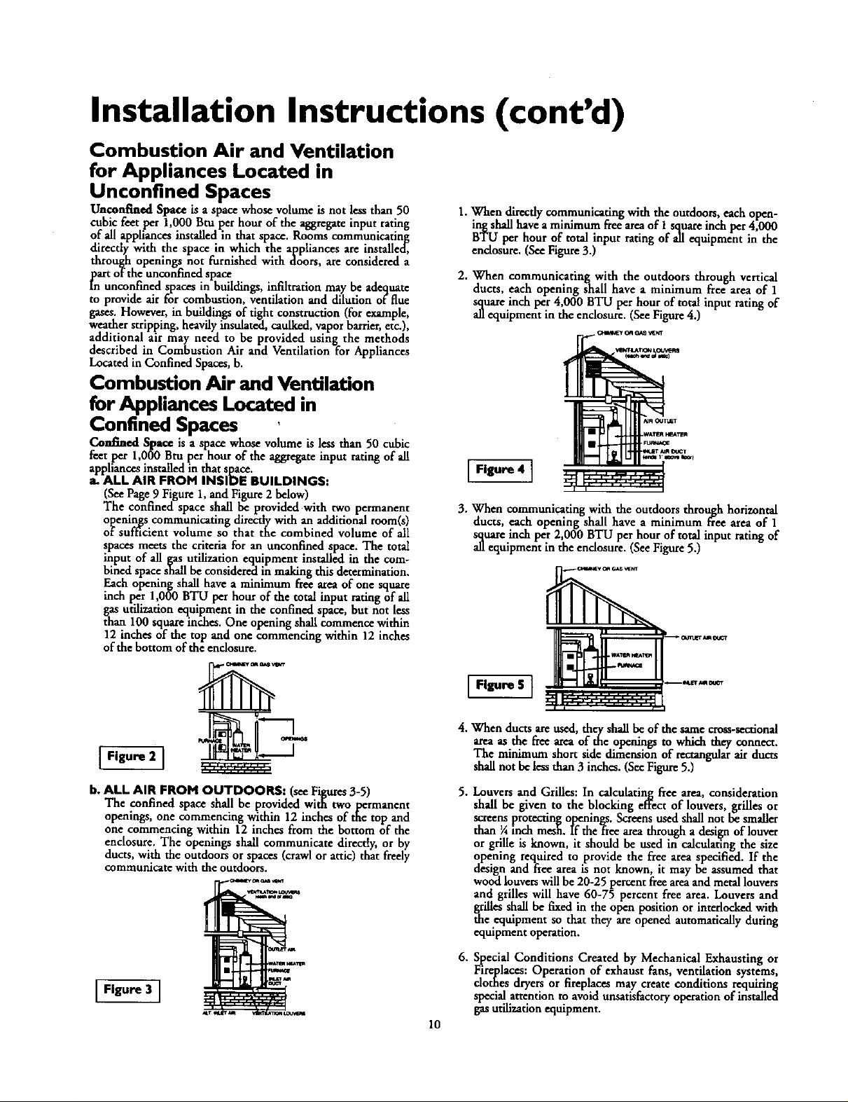
1.When direcdycommunicating with the outdoors,each open-
ing shallhaveaminimumflee areaof I squareinch per 4,000
BTU per hour of total input raring of all equipment in the
enclosure.(SeeFigure3.)
2. When communicatingwith the outdoors through vertical
ducts, each opening shall have a minimum free area of 1
sc!uareinch per 4,000 BTU per hour of total input ratingof
all equipment in the enclosure.(SeeFigure4.)
Figure 4 ]
3. When communicating with the outdoors through horizontal
ducts, each opening shall have a minimum free area of 1
square inch per 2,000 BTU per hour of total input rating of
all equipment in the endosure. (SeeFigure5.)
I Figure 2 ]
b. ALL AIR FROM OUTDOORS: (seeFigures3-5)
The confined space shall be provided with two permanent
openings,one commencing within 12 inchesof tee top and
one commencing within 12 inches from the bottom of the
enclosure. The openings shall communicate directly,or by
ducts,with the outdoorsor spaces (crawlorattic) that freely
communicatewiththe outdoors.
I Figure 3 ]
[el,-- ....
4.When ductsare used, they shallbe ofthe same cross-sectional
areaas the free area of the openingsto which they connect.
The minimum short side dimensionof rectangularair ducts
shallnot be lessthan 3 inches.(SeeFigure5.)
5. Louversand Grilles: In calculating free area, consideration
shall be given to the blocking effect of louvers, grillesor
screensprotecting openings.Screensused shall not be smaller
than ¼inch mesh.If the_ee area through a desi_ of louver
orgrilleis known, it should be used in calculating the size
opening recLuiredto provide the free area specified. If the
designand free area is not known, it may be assumed that
woodlouverswillbe20-25 percent freeareaand metallouvers
and grilleswill have 60-75 percent free area. Louversand
grillesshall be fixedin the open position orinterlocked with
the .equipment so.that they are openedautomaticallyduring
equipmentoperation.
6. Special Conditions Created by Mechanical Exhaustingor
Fireplaces:Operation of exhaust fans,ventilationsystems,
clothesdryersor fireplacesmay create conditions requiring
specialattention to avoid unsatisfactoryoperationof installed
gasutilizationequipment.
1o
_i " ....... Ii f I
Installation Instructions (cont'd)
Water Piping
AWARNING
HOVrERWATERCANSCALD:.Waterheatersareintendedto
producehot_ Waterheatedto a temperaturewhichwill
satisfyclotheswashing,dishwashing,andothersanitizingneeds
_n sealdandpmnanentlyInjureyouuponcontoc_Somepe_
piem_emore Wadyto be pem_nen_ injured byhot w_er _
others.TheseI_fude t_ elde_ ddldren, the k_irm,orp_sk_
ly/mentallyhandicapped.Ifanyoneusinghot waterinyourhome
Etsintooneofthese gruupsor ifthere isa localcadeorstatolaw
requiringa certaintompeeature _ atthehot watortap,then
foumusttakespecialprecaudom.Inadditionto usingthelowest
)ossiblettmperatum set,rigthatsatisEesyourhotwaterneeds,
_meanssuchasa mixingvalve,shouldbeusedatthehotwater
tapsusedbythesepeopleorot the woterheater.Mixingvalves
aruwallableatplumbingsupl_yorhan_r_xestoreLFollowman-
ufacturersinstructionsfor installationof thevalves.Before
changingthe factory settingon the thermostat,read the
"TemperatureRegulation"sectioninthismanual.
This waterheater shallnot be connected to any heating systems
or component(s) used with a non-potable water heating
appliance.
If a water heater is installed in a closed water supply system;
such as one having a back-flow preventer, check valve, water
meterwith a check valve,etc.., in the cold water supply; means
shall be provided to control thermal expansion. Contact the
local utility or localSearsServiceCenter on how to control this
situation.
NOTE: Toprotect against untimely corrosion of hot and
cold water fitthags,it is steon_iy recommended that all-elec-
tric unions or couplings be mstelled on this water heater
when connected to copperpipe.
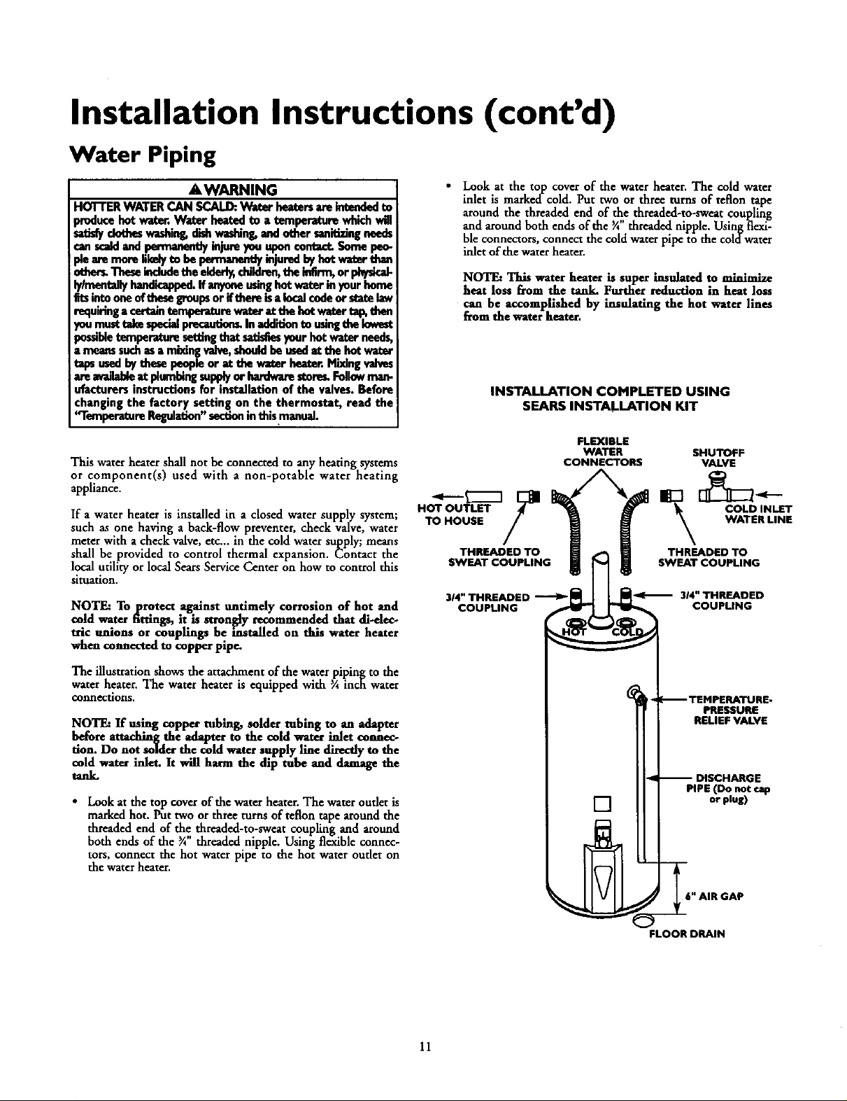
• Look at the top cover of the waterheater. The cold water
inlet is markedcold. Put two or three turnsof teflon tape
around the threaded end of _e threaded-to-sweat coupling
and around both ends of the ¾ threaded nipple. Usingflexi-
ble connectors,connect the cold waterpipe to the coldwater
inlet of the waterheater.
NOTE: This water heater is super insulated to minimize
heat loss from the tank. Further reduction in heat loss
can be accomplished by insulating the hot water lines
from the water heater.
INSTALLATION COMPLETED USING
SEARS INSTALLATION KIT
FLEXIBLE
WATER SHUTOFF
CONNECTORS VALVE
HOT OUTLET COLD INLET
TO HOUSE WATER LINE
THREADED TO _ THREADED TO
314"THREADED _ _ 314"THREADED
COUPLING COUPLING
SWEAT COUPLING_ SWEAT COUPLING
The illustration shows the attachment of the water piping to the
water heater. The water heater is equipped with 3Ainch water
connections.
NOTE: If using copper tubing, solder tubing to an adapter
before auaching the adapter to the cold water inlet connec-
tion. Do not solder the cold water supply line directlyto the
cold water inlet. It will harm the dip tube and damage the
tank.
• Look at the top coverof the waterheater.The water oudet is
markedhot. Puttwo orthree turns of teflon tape around the
threaded end of the threaded-to-sweat coupling a-,xdaround
both ends of the _A"threaded nipple. Using flexible connec-
tors, connect the hot waterpipe to the hot water outlet on
the waterheater.
11
_ TEMPERATURE-
PRESSURE
RELIEF VALVE
-- DISCHARGE
PIPE (Do not cap
[]
,_ _6" AIR GAP
FLOOR DRAIN
or plug)

Installation Instructions (cont'd)
Temperature-Pressure Relief Valve
A, WARNING
At the time of manufacturethis water heater was provided
with acomb_nat;_nm_ratu_--,_ures relief valvecerti_d
by a nationally recognized testing laboratory that maintains
periodicinspectionof productionoflistedequipmentor mate-
rials, as meeting the requirements for Relief Valves and
AutomaticGasShutoffDevicesfor Hot Water SupplySystems,
and the latest edition of ANSI Z21.22 and the code require-
mentsof ASME. If replaced,thevalve must meat the require-
mentsof localcedes,butnot lessthan acombinationtempera.
ture andpressurerelief valvecertifiedasmeeting the _luire-
meritsfor ReliefValvesandAutomaticGasShutoffDevicesfor
Hot Water SupplySystems,AHSLZ2|.Z2 by anationallyrecog.
nizedtesting laboratorythat maintainsperiodicinspectionof
productionof llstedequipment or materials.
The valve mustbe made:d with a maximum set presserenot
to exceed the marked hydrostatic working pressureof the
water heater(I 50IbsJsq.in.) and a dischargecapacitynot less
than thewater heaterinput rateas,shownon the modelrating
plate. (Electric heaters • watts dividedby 1000x 3415 equal
BTU/I-Ir.rate.)
Yourlocaljurisdictionalauthority,whilemandatingtbe useof a
temperature-pressure reliefvalvecomp,Wyingwith ANSI 7.21.22
and ASME,may requirea valvemodeldifferentfrom the one
fomished withthe waterheater.
Compliancewith suchlocalrequirements must be satisfiedby
the installeror end userof the water heaterwitha locallypre-
scribedtemperature-pressure reliefvalveinstalledin the desig-
nateclopeninginthe water heater in placeof the factoryfur-
nishedvalve.
Forsafeoperationofthe water heate_,the relief valvemust not
bemrnovedfrom it'sdesignatedopeningor plugged.
The temperature-pressure reliefvalvemustbe installeddirectly
intothe fittingofthewaterheaterdesignatedforthe relief valve.
Pesltlenthevalvedownwerdandpravidetebing so that anydi_
chargewillexit only within 6 inchesabove,or at anydistance
below the structuralfloor.Be certainthat nocontactis made
with anyliveelectricalpart. Thedischa_eopeningmustnot be
Mocked or reduced insizeunderanycircumstances.Excessive
length, avev30 fa_€,er useofmere th_ fonr elbewscancause
restriction andreducethe dischargecapecityofthevalve.
No valveor other obstructionisto be placedbetweenthe relief
valveand the tank. Do nutconnecttubingdirectlyto discharge
drainunlessa6" airgapisprovided.Topreventbodilyinjury,haz-
ardtolife,or propertydamage,the relief valvemustbe allowed
todischargewater inquantitiesshouldcircumstancesdemand.If
the dischargepipeisnot connectedto adrain or othersuitable
means,the water flowmaycausepropertydamage.
The DischargePipe:
Must not be sm_ller in size than the outiot pipe size of the
valve,or haveanyreducingcouplingsor other restrictions.
Mustnot bepluggedor blocked.
Mustbeof material listedfor hot water distribution.
Mustbe installedso asto allow completedrainageof both
the temperature-pressure relief valve, and the discharge
pipe.
Mustterminateat an adequatedrain.
Mustnot haveanyvalvebetweenthe relief valveandtank.
A WARNING
The temperature-pressure relief valve must be manually
operated ot least on©ea year,Cantion shoukl be taken to
onsore that (I) no one isin front of or around the oudet of
the temperoture-peessurerefiofvalvedischargeline,and (2)
the water manually discharged will not cause any bodily
injury or property damage because the water may be
extremely hot.
If after manually operating the valve, it failsto completely
reset and continuesto releasewater_immediately dosethe
cold water inlet to the water heater, follow the draining
instructions, and replace the temperature-pressure relief
valvewlth a new ane.
-II--- q
HOT SHUTOFF COLD
FLOOR DRAIN
VALVE
PRESSURE
REUEF VALVE
PiPE
(Do not cap or plug)
6" AIR GAP
RELIEFVALVEOPENING
At sfiedineof manu_'mre,thiswaterheaterv_s edwisha €ombfoedontera-
;_-_u_ rd_ va_e_sted_sconing _'w_ _an_ for_ _ _d
automaticg)sshut-offd_ces forhotwatersupplysy_ems,ANSI7)1.22.Forsafo
opera_oeofshewaterheater,_be_ief vahemustn_ beremovedfromitsdesignated
pointofinstaria_onorplng_l.
relief_ complyingwithANSI7.21.22andASMF.mayrequireavahemodeldiffe_nt
fromtheonefurnishedwiththewaterhea_e_
ofC_iancewishsuchlocalrequirementsmustbesatisfiedby_e installerorenduser
waterheaterwi_haIo_11_prescribedter_erature-pr_sure_ief valveIn.ailed
inthedesignatedopeninginthewa_erbea_.
Seemanualbe_ding-"Temper_tur_PressureReliefValves"forinstalb_onant;mainte-
nanceofreliefvalve_dischargeline,andostlersafer/precauri_n_.
12

Installation Instructions (cont'd)
Filling the Water Heater
ACAUTION
Nev_ usethis water hex/;erunlessit iscompletelyfilled with ]
water.To praventdamagete the tank, the tank mu_ be filled]
with water. Water must flow from the hot water faucet
beforetumng 'ON gnsto the water heater,
To fill the water heater with water:
• Close the water heater drain valve by turning the handle to
the right (clockwise). The drain valve is on the lower front of
the water heater.
• Open the cold water supply valve to the water heater.
NOTE: The cold water supply valve must be left open
when the water heater is in use.
• To insure complete filling of the tank, allow air to exit by
opening the nearest hot water faucet. Allow water to run
until a constant flow is obtained. This will let air out of the
water heater and the piping.
• Check all new water piping for leaks. Repairas needed.
Venting
A WARNING
VENT DAMPERS. Any vent damper,whether it isoperated
thermaJlyor otherwisemustbe removedifitsuseinhibitsprop.
er drdCingof thewaterhe_er.
Thermally Operated Vent D_rnpers:Gas-firedwater heaters
havingthermal et_ency in excessof 80%may producea rela-
_vely lowfluegastemperature. Suchtemperaturesmaynot be
high enough to properly open thermally operated vent
danll_H,s.Thiswouldcausesptll_ offlue pses midmayQuse
carbonmonoxidepoisoning.
Ventdampersmustbear evidenceofcertificationascomplying
with the latest edition of American NationalStandard ANSI
7.21.68(ANSI Z21.6_ & 67, respectS, coverelec_;callyand
mechank:al_/ac_ vent dan_). Boforeim(:all,_ of any
ventdampe_consuityourlocalSearsServiceCenteror the gas
AWARNING
To insureproper venting of this gas-firedwater heater, the
correct ventpipe d'_-_er must beutilized,Anyadditionsor
deletlom of other ps appliancesona commonvent with this
water heater maqfadverselyofrectthe operation of the water
heater.Consultthe localSearsService Center or gasudllty if
anysuchchangesare planned.
Forproper ventingin certain installations,a largerdiametervent
pipe may benecessary.Due to greatvariancesin installations,
unforeseeableby themanufacturerof the water heater,you must
consult your gas company to aid you in determining the proper
ventingfor yourwaterheaterfromthe venttablesinthelatestedi-
tion of the NationalFuelGas CodeANSIZ223.1, alsoreferredto
asNFPA 54.
Check the ventingsystemfor signsofobstructionor deterioration
and replaceifneeded.
Thecombustionand ventilationairflowmustnot beobstructed.
AWARNING
heaithriskor_.
• Place the draf_ hood legs in the receiving holes on the top of
the water heater. The legs will snap in the holes to give a tight
fit.
• 1
Phce the vent pipe over the drafthood. With the vent pipe in
position, drill a small hole through both the vent pipe and
draft hood. Secure them together with a sheet metal screw.
ORAFTHOOO41' IVeNT J
f SCR_ DRAFT HOOD
DRAFT H( OD_VEI_ITNTE_OUTDOORS,,N
AWARNING I
ThewaterhexterwlthdrafthoodInstalledmustbeproperlyI
ventedtoa chimneywhichterminatesoutdoors.Neveroper-I
atethe_ hext_runlessit isventecltothe outxJoorsandhas[
adequateairsupplyte avoidrisksof improperoperation,explo-
sionorasphyx_on.
AWARNING I
The _mt pipefrom the water heater mustbe no lessthan the I
diameter of the draft hood outlet on the water heater, and
_)o_S ope upward to the chmneyat east '/4nchper near
OR
13

Installation Instructions (cont'd)
Venting (cont'd)
Allventgasesmust be completelyvented to the outdoorsof the
structure (dwelling). Instal[only the draft hood provided with
the new water heater and no otherdrafthood.
Ventpipesmust besecured at eachjoint with sheet metal screws.
CHIMNEY
TO
RISE PFEc_NEAR I
!
VENT PIPE INSTALLATION
There must be a minimum of 6" dearance between single wall
vent pipe and any combustible maserial.Fill and seal any deat-
ancebetween single wall vent pipe*and combustible material
with mortarmix, cement, or other noncombustible substance.
Forotherthan singlewall, follow ventpipe manufacturer'sdear-
0axcespecifications.To insure a dgb-t fit of the vent pipe in a
brick chimney, seal around the vent pipe with mortar mix
cement.
AWARNING
Failureto havemqulrecl.,durances betweenventpipingand
combustible _ willremit Ina Emhazard.
Besureventpipeisproperlyamnoctodto preventnscapeof
dangemmIlueSasnswhich€ouldcausedead_asphln_o_
AWARNING ]
Gas Piping
AWARNING
Makesurethe gassuppliedisthe sametypelistedon the
modelns_ngpia_ The Inlntgaspressurenmstnnt exceed
10.S in. water column ('].61d_) for natuili gas or 13 in.
column(3.2kPa)forpropane(I.R) gas.The minimuminlet
gaspressurelistedon the modelredng plateisfor the pur-
pose04'inputadjustment.
AWARNING
Ifthegescona'olvaiveIssubjectedto pressuresexceeding½]
poundpersquareinch(3._la_a),the damageto thegascon-I
tmlvelvecouklrnsultinatimorexplosionfromleaidnggel J
AWARNING
] If themaingaslineshutoffservingallgasappliancesisused,]
Ialso tom "off" the ges et each appliance. Leaveall gas appii-J
I th" I
A gas line of su_cient size must be tun to the water heater.
Consult the latest edition of National Fuel Gas Code ANSI
Z223.1,alsoreferredto as NFPA54 and the gascompanyconcern-
ingpipesize.
There mustbe:
• A readilyaccessiblemanualshut off valvein the gassupplyline
servingthewaterheater,and
• A dripleg (sediment trap)aheadof the gascunt_rolvalveto hdp
preventdirt and foreign materialsfrom entering the gascontrol
valve.
• A flexiblegasconnector or a groundjoint union between the
shutoffvalveand controlvalveto permit servicingofthe unit.
AWARNING
Chemicalvaporcorrosionof the flueand vent systemmay
occurifair for combustioncontainscertainchemicalveporL
Spraycan pmpellonts,deaningsolvents,refrigeratorKtd air
conditionerrefrigerants,swimmingpoolchemicals,calcium
andsodiumddoride,waxe_bleach,andprocesschemlcalsare
typicalcompoundswhicharepotentially€orrnslve.
Be sure to check all the gas piping for leaks before lighting the
water heater. Use a soapy water solution, not a match or open
flame. Rinse offsoapy solution and wipe dry.
Standard Models are for imtattadon up to 3,300 feet above sea
level.
fl_h Altltud¢ Models are for insm]htion from 3,300 to 5,500
ahove sea levd.
If a standard toodd isinstalled above 3,300 feet or a high altitude
model is installed above 5,500 feet, the input rating must be
reduced at the rate of 4 percent for each 1,000 feet above sea level.
Contact your local Sears Service Center or gas udlity for further
information.
AWARNING
The applianceand its gasconnectionmustbe leaktested
befo_p_clagtheafCl_acemoperaUo_
14

Installation Instructions (cont'd)
AWARNING
• Theq3pliancerand_ individualshutoffvalsemasthediscon-
nectedfromthelas_3ply pipingI_-m duringmr¢prassure
testingof the gassystemat test pressuresinexcessof
. peundpersc_relech(3.SkP',).
Theapprmsemustbeiselatedfromthe_s supplypipinlsys-
ternbydosingitsindividualmanualshutoffvalveduringany
pressuretastingofthe gassupplypipingsystemat testpras-
suresequalorless_ _ poundpersquareinch(3.5kPa),
I &WARNING
Usepipejoint compoundor teflon tapemarkedasbeingJ
SEDIMENT TRAP
A sediment trap shall be installed as close to the inlet of the
waterheater as practicalat the time of waterheater installation.
The sediment trap shallbe eithera teefittingwith a cappednip-
ple in the bottom oudet or otherdevicerecognized asan effec-
fivesediment trap. Ira tee fitting is used, it shall be installedin
conformance with one of the methods of installation shown
below.
Connecting the gaspiping to the gascontrol valveof the water
heater canhe accomplishedby either ofthe twomethods shown.
GAS PIPING WITH
FLEXIBLE CONNECTOR
GROUND
CAP
LOOP
GAS
CONTROL
VALVE
GAS PIPING WITH ALL BLACK IRON
PIPE TO GAS CONTROL
AWARNING
ContaminentsIntheIpsrmesn_/came i_ oper_on
of the gas€ontrolvalvethat r,_/rasult intireor expleslen.
Be(oreIttKhleg thegasIleehesurethatangaspipeisdean
ontheimlde.To_ap anydirtor foreignmateslalInthe gas
supplyline, a drip leg (sometimes called a sediment trap)
must be incocperated in the piping.The drip leg must he
readilyaccessible.Installinaccordancewith the "Gas Piping,"
sectine.Refer to the letest ediUonof the National FuelGas
Code, ANSI 7.223.1,alse re_-md to as NFPA 54.
LJCAP
15

Installation Instructions (cont'd)
Installation Checklist
BEFORE LIGHTING THE PILOT:
• Check the gaslines for leaks.
a. Use a soapy water solution. DO NOT test for gas leaks
usingamatch or open flame.
b. Brushthe soapywater solution on all gaspipes, joints and
fittings.
c. Check for bubbling soap• This means you have a leak.
Turn OFF" gasand makethenecessaryrepairs.
d. Recheckfor leaks.
e. Rinse offsoapy solution and wipe dry.
• Isthe new temperature-pressurereliefvalveproperly installed
andpiped to art adequate d_in? See _Temperatttre-Pressure
ReliefValve"section•
• Are the cold and hot water lines connected to the water
heater correctly? See "Water Piping" instructions in the
_lnstallation Instructions _ section.
HOT
VENT PIPE TO
OUTDOORS
OR CHIMNEY
DRAFT HOOD
UNION
SHUTOFF VALVE
COLD
• Is the water heater completdy filled with water? See "Filling"
instructions in the Installation Instructions section.
• Will a water leak damage anything? See the "Facts to
Consider About the Location" section.
• Is there proper clearance between @e water heater and any-
thing that might catch fire? See the Facts to Consider About
the Location" section.
• Do you have adequate ventilation so that the water heater
will operate propetly? See Combustion Air and Ventilation
in the _Facts to Consider About the Location" section.
• Is the draft hood vent piping proper secured. See Ventmg_
instructions m the Installation Instructions section.
• Is there proper dearance betw_n the vent pipe and anything
that might catch on fire. See Venting instructions in the
'" ly ....
"Installation Instructions" section.
• Is the vent pipe properly sloped and does the vent terminate
outdoors? See "Venting" instructions in the "Installation
Instruct ons seCtiOn.
• Do you need to call your gascompany to check the gaspipe
and itshookup?
GAS SUPPLY
TEE
(Sediment
trap) PIPE CAP
DRAIN VALVE '
SHUTOFF VALVE
PRESSURE
REUEF VALVE
(Do not rap or plug)
i
6" AIR GAP
FLOORDRAIN
16
MODEL RATING PLATE

Operating Instructions
Lighting
A WARNING
BEFORE LIGHTING [PROPANE (L.P.) GAS WATER
HEATERS]:Propane(L.R) gasis heavierthan air.Shouldthere
be a leak in the system,the gaswill settle near the ground.
Basements,crawl spaces,skirted areas undermobile homes
(evenwhenventilated),closetsandareasbelowgroundlevelwill
serve as pockets for the accumulation of this gas. Before
attemptingto lightorrelightthewater heater'spilotor turning
ona nearbyelectricallight switch,be absolutelysurethere isno
accumulatedgasinthearea.Searchforodorof gasbysniffingat
groundlevelinthe vicinityofthe appliance.If odor isdetected
followstepsindicatedat"For YourSafety"onthe coverpageof
thismanualthen leavethe premises.
Lighting and operating instructions are located on front of the
water heater, above or to one side of the gas control valve.
_,WARNING
AN ODORANT ISADDED TO THE GAS USED
FOR YOUR SAFETY
IF YOU SMELL GAS:
• Do not try to lightanyappliance.
• DOnot touch anyelectricalswitch;donot useanyphone in
your building.
• Immediately callyour gassupplierfrom aneighbor's phone.
Follow the gassuppiier_instruedons.
• If you cannotreachyour gassupplier,call the fire depart-
merit.
BY THIS WATER HEATER.
Figure 6
Figure 7
AWARNING
DO NOT forcethe gescontrnlImob. Use only your hand to
pushit downto lightthe pilot, or to turn it to "ON", "OFF"
or "PILOT". Never use atool such as a lever,w_nch or pli-
ers. Do not hit or damage the knob. A darnagedImob may
resultin an explosionandsuHous injury.If you haveproblem
turningtheImob,callthe gassupplier immediately.
CHECK FOR LEAKS
Be sure to check all your gas pipes for leaks before lighting your
water heater. Use a soapy water solution, not a match or open
flame. Check the factory gas fittings after pilot is lit and gas con-
trol knob is still in "PILOT" position. Then, check the fittings
when the main burner is turned "ON". Use a soapy water solu-
tion for this, too.
17
Figure 8
Figure 9
_INNER DOOR
OUTER
DOOR

Operating Instructions (cont'd)
Lighting label on the water heater as it appears above the thermostat
FOR YOUR SAFETY READ BEFORE LIGHTING
If you do not follow these instructions exactly, a fire or explosion
may resut caus ng property damage, personal injury or oss of I re.
A. Thisappliancehas a pilotwhichmustbelightedby
hand.Whenlightingthepilot,followtheseinstructions
exactly.
B.BEFORELIGHTINGsmellallaroundtheappliancearea
forgas. Besureto smellnext to thefloorbecause
somegasIsheavierthanairandwillsettleonthefloor,
WHATTODOIFYOUSMELLGAS
• Donottry tolightanyappliance.
• DOnottouchanyelectricswitch;do notuseany
phoneinyourbuilding.
• Immediatelycallyourgassupplierfroma neighbor's
phone,FollowthegassuppJier'sinstructions,
WARNING i
LIGHTING INSTRUCTIONS
1.STOP!Readthesafetyinformationaboveonthislabel.
2.Removeouterdoor.
3. Satthethermostatto lowestsetting,byturning the
watertemperaturedialclockwise,(( _,)to itslowest
temperaturesetting(witharrowondial)asshown.DO
NOTFORCE.
4,Turngascontrolknobclockwise_) to "OFF"posi-
tion.Knobcannotbeturnedfrom"PILOT"to"OFF"
unlessknob is depressedslightly.DO NOTFORCE.
(Figure6, page17)
5.Waitfive(5) minutesto clearoutanygas.Ifyouthan
smellgas,STOP!Follow"B" inthe safetyinformation
aboveonthislabel.If youdon'tsmellgas,go to the
nextstep.
6. Remove(or open)innerdoorlocatedbelowthegas
controlunit.
7.Findpilot-followmetaltubefromgascontrol.Thepilot
islocatedInfrontoftheburner.
PILOT BURNER _ I THERMOCOUPLE
8.IfyoUdon'tsmellgas,turnknobongascontrolcounter
clockwlse_,_' to "PILO'F"position.(Figure7,page17)
tLX_
• If youcannotreachyourgassupplier,callthefire
department.
C. Useonlyyour handtopushinortumthegascontrol
knob.Neverusetools.Iftheknobwillnot pushinor
turnbyhand,don'ttryto repairit,calla qualifiedser-
vicetechnician.Forceorattemptedrepatrmayresult
inafireorexplosion.
D.Donotusethisapplianceif anyparthasbeenunder
water,tmmedictelyca, a quaitfledservicetechnician
toinspecttheapplianceandtoreplaceanypartofthe
controlsystemandanygascontrolwhichhasbeen
underwater.
g. Pushin control knoball thewayandholddown.
Immediatelylightthepilotwitha match,Continueto
holdcoutmtknobin foraboutone(1)minutealter
thepilotIslit.Releaseknobanditwillpopbackup.
Pilotshouldremainlit.If it goesout,repeatsteps3
through8.
• it knobdoesnotpop upwhenreleased,stopand
immediatelycallyourservicetechnicianorgas
supp,m.
• If the pilotwill notstay lit afterseveraltries,
depR*ssandturnthegascontrolknobclockwise
i(_ _ to"OFF"ahdcallyourservicetechnician
orgassupplier.(Figure6,page17)
10.Replace(orclose)Innerdoor.Replaceouterdoorif
doordoesnotcovergascontrolon/offknobortam-
paratureadjustmentknob.(Figure9,page17)
11. Atarmslengthaway,turngascontrolknobcounter-
clockwise_ tothefull "ON"position.Wanting
do not use gas controlknob to regulate gas
flow.(Figure8,page17)
12.At armslengthaway,setthethermostatto desired
setting.Themark( • ) HOTindicativeof approximate
120°Fis preferredstartingpoint.Somelocallaws
mayrequirea lowerstartingpoint,If hotterwateris
desired,seeinstructionmanualand"warning"below.
13.ReplacetheouterdoorIf notreplacedinstep10.
I WARNING
Hotterwaterincreasestheriskofscaldinjury.Beforechangingtemperaturesettingseeinstructionmanual.
TO TURN OFF GAS TO APPLIANCE
1.Setthethermostatto lowestsettingbyturningthe
watertemperaturedialclockwise(F'_) to Its lowest
temperaturesetting(witharrowondial)asshown.DO
NOTFORCE,
2. Turngascontrolknobclockwise_') to "OFF"
position.Knobcannotbeturnedfrom"PILOT" to
"OFF"unlessknobis depressedslightly.DONOT
FORCE.
3.Replaceouterdoor(ifremoved).
18

Operating Instructions (cont'd)
Temperature Regulation
Due to the nature of the typical gas water heater, the water tem-
_oerature in certain situations may vary up to 30°F higher or
wet at the point of use such as, bathtubs, showers, sink, etc.
This means that when the temperature adjustment dial is set at
the mark approximating 120° F, the actual water temperature at
any hot water tap could be as high as 150°F or as low as 90°E
Any water heater's intended purpose is to heat water. Hot water
is needed for cleaning (bodies, dishes, clothing). Hot water will
present a scald hazard. Depending on the time element and the
people involved (normaladults, children, toddlers, elderly,
infirm, etc.) scalding may occur at different temperatures.
AWARNING
HOTTER WATER CAN SCALD: Water heatersare intendedto
prod.uco hotwater. Water heatedto a temperature whichwill
sa'dsfyclotheswashing_dishwashing,andother sanitizingneeds
canscald_ndpermanently injure youupon contact.Some peo-
ple aremore likelyto bepermanently inuredby hot water than
othem Theseindudethe elderly,children,the infirm,or physical-
lylmentallyhandicapped.If anyoneusinghotwater inyour home
fitsintooneofthesegroupsor ifthere isa localcodeor statelaw
requiringa certaintemperature waterat the hotwater tap,then
_mmusttakespecialprecautions.In additionto usingthe lowest
mssibletemperature settingthat satisfiesyourhot water needs,
Lmeanssuchasa mixingvalve,shouldbe usedat the hot water
tppsusedbythese peopleor at the water heater Mi_ingvalves
are availableat plumbingsupplyor hardwarestore_Followman-
ufacturers instructions for installation of the valves. Before
changing the factory setting on the thermostat, read the
'q'emperature Regulation"sectioninthismanual.
Turn the water temperature dial clockwise (ff"_) to decrease
the temperature, or counterclockwise (_",_) to increase the
temperature.
PILOT LIGHTING-Set here before attempting to light pilot.
• HOT-Is a thermostat setting of approximately
120°F,whichwillsupply hot waterat the
most economical temperatures. The
temperature adjustment knob can be
turned lowerthan "HOT"ifdesired.
A-Is a thermostat setting of approximately
130°E
B-Is a thermostat setting of approximately
140°F. This is the lowest setting for
supply of hot water to dishwashers.
AWARNING J
Neverallowsmallchildrento usea hotwater_ or todraw
thalrownbathwater,Neverleaveachildor handicappedper-I
sonunattendednabathtubor shower. I
The thermostat of this water heater has been factory set at its
lowest position, to reduce the risk of scald in ury. It is adjustable
and must be reset to the desired temperature setting. The mark
(•) HOT indicative of approximately 120°F is title preferred
stattin_ point. Some states have a requirement for a lower set-
ting. Iryou need hotter water, follow directions for temperature
adjustment, but beware of the warnings in this section.
C-Is a thermostat setting of approximately
150°E
VERY HOT-Is a thermostat setting of 160°F. It is
recommended that the dial be set lower
wheneverpossible.
NOTE: Water temperature range of 120°--140°F recom-
mended by mostdishwasher manufacturers.
AWARNING
Shouldoverheatingoccuror the gassupplyfailto shutoff,
turn"OFF" themanualgascontrolvalvetotheappliance.
19

Service and Adjustment
Tank (Sediment) Cleaning
Sediment build-up on the tank bottom may create varying
amounts of noise, and if left in the tank will causepremature
tank failure. In some waterareas, you may not be ableto drain
all sediment depositsby simply drainingthe tank. In thesecases
MagErad (part no. 23600) can be used to help remove the sedi-
ment deposits. This may be ordered from the Sears Service
Center. Forordering,referto the "Repair Parts"section.
Venting System Inspection
At least once a year a visual inspection should be made of the
venting system. You should look for:
• Obstructions which could cause improper venting. The com-
bustion and ventilation air flow must not be obstructed.
Damage or deterioration which could cause improper vent-
ing or leakage of combustion products.
Rusted flakes around top of water }_eater.
&WARNING
Chemical vapor corrosion of the flue and vent system may
,occur if air for combustion contains certain chemicalvapors.
! Spray can propellants,cleaningsolvents,refrigerator and air
conditioner refrigerants, swimming ponl chemica/s,calcium
andsodiumchloride,waxes,bleach,and processchemicalsare
typicaicompoundswh chare potentiallycorrosive.
AWARNING
Obstructedor deteriorated ventsystemsmay presenta serious
heaithriskorusphyxiation.
Burner Inspection
AWARNING I
Do ont usethisapldianceif anypert of it hasbeenander water. _
Immediately call a Sears Service Technicianto inspect the I
applianceand to replace the gas control or any part of the
burner systemwhchhasbeen underwat_
At least once a year a visual inspection should be made of the
main burner and pilot burner. The drawing is for your reference.
You should check for sooting which is not normal and will
impair proper combustion.
AWARNING J
Soot build-up indicates a problem that requires correction
beforefurther use.Turn "OFF" gasto water heater and leaveI
"OFF" until repairs are made, becausefailureto correct the
causeof the sootingcan result in a fire or explosioncausing
DEATH, SERIOUSBOD LY NJUI_, OR PROPERTYDAMAGE.
Burner Cleaning
AWARNING [
Be sure the vent piping is properly connected to prevent ]
escape of dangerous flue gosseswhich could cause deadly
asphyxation.
AWARNING I
If after inspection of the vent system you found sooting or I
deterioration, somethingiswrong. Call the localgas utilityto ]
correct the problem anddean or replace the flueand venting
beforeresumng operation ofthe water heater.
In the event your burner needs cleaning, use the following
instructions:
If inspection of the burner shows that cleaning is required, turn
the gas control knob dock'wise (ff"x) to the "OFF" position,
depressing slightly.
NOTE: The knob cannot be turned from "PILOT" to "OFF"
unless knob is dept-'_,sedslighdy. DO NOT FORCE.
Loose deposits on or around the burner can be removed by care-
fully using the hose of a vacuum cleaner inserted through the
access door of the water heater. If the burner needs to be removed
fo_ additional cleaning, call the Sears Service Center to remove
and clean the burner and correct the problem that required the
burner to be cleaned.
2O

Service and Adjustment (cont'd)
I-R Gas Control Valve & Burner
Assembly Replacement
Information
&WARNING
PROPANE (L.R) GAS CONTROL VALVE AND BURNER
ASSEMBLY REPLACEMENT INFORMATION.
For Propane(I.R) Gas ModelsOnly:,
Your water heater is equippedwi_ • Propane (I-R) gascon-
troi valveand a main burner assemblywith left:handthreads
forthe followingfittingsand their connections.
• The connecdon between the manifold and the gas
cont_ v_ (A _o B) are left hand threads_
• The connection between the main burner orifice
and che manifold (C to D) are left hand threads.
For ordering these replacement parts, please refer to
the "Repair Parts" section ofthi_ manual.
Temperature-Pressure Relief
Valve Operation
Tb_e tcmperatu_-pressu_ rdief vatve must be man_ally operated
at least once a year.
TEMPERATURE-PRESSURE
RELIEF VALVE
/
DISCHARGE P!PE
Failureto install and maintain a new properly listed tempera-
ture-pressure rdiefvalvewillreleasethe manufacturerfrom any
claimwhich might resultfrom excessivetemperature orpressure.
AWARNING
If the temperstur_prasserereliefvalveon the appliance
wanpsecdisd_q_s periodicall_this maybedueto thermai
expansion,Yourwater heater may have a checkvalve
installedIn the water lineor s water meter with a check
valv_Consultthe SearsSecvicoCenterfor furthecinforma.
don.Donotplugthetemperature-peassurerailervalve.
Draining
The water heater should be drainedif being shut down during
freezing temperatures. Alsoperiodic draining and cleaning of
sediment from the tank maybe necessary.
Turn the gascontrol knob to the _OI_F"position.
CLOSE the cold water inletvalveto thewater heater.
• OPEN a nearbyhot water faucet and leaveopen to allow for
draining.
• Connect a hose to the drain valve and terminate to an ade-
quate drain.
• OPEN the water heater drain valve to allow for tank
draining.
NOTE: If the water heater is going to be shut down and
drainedfor an extended period, the dra_ valveshould be
left open with hose connected allowing waterto terminate
to an adequatedrain.
• Closethe ctrainvalve.
• Follow instructions in the "Filling The Water Heater"
section.
• Followthe lighting instructionsin the "Lighting" section to
restartthe waterheater.
&WARNING I
Whanchedd_ thetempereteretammrer_ va_eopera-
tio_ male mm _at (I) no one is in front of or asound the
outlet of the _anperatemtammre reliefvalvedisdwlle line,
and(2)_ thewmr manual/a_hargedwmnot€_.e any
pmper_ dam_e beaue thewaternW beexm._y hot
If after manually operating the valve, it _ls to completely
reset ancicontinuesto _qease w'_er, immediate_ dose the
cold water inlet to the water heater, follow the draining
instructions, and replace the temperature-pressure relief
wive wi_ a ouw one.
21

Service and Adjustment (cont'd)
Drain Valve Washer
Replacement
NOTE_For replacement,use a '_" x "/_"x ½" d,i.'ckwasher
available at your n¢_u-esthardware.to_ For ordmlng _phce-
meritwashers,n&mto thc "l_m O_lc: Li_ section.
Turn _OFF" gassupply to waterheater.
Follow Draining insu'uctions.
Turning counter clockwise, remove the hex cap below the
screwhandle.
• Removethe washerand put the new onein place.
Screwthe handle and cap assembly back into the drainvalve
and retightenusing a wrench. DO NOT OVER TIGHTEN.
Follow instructions in the "Filling The Water Heater"
section.
• Check for leaks.
Followthe lightinginstructions in the *Lighting" section to
restartthe waterheater.
HANDLE
ASSEMBLY
Housekeeping
Vacuumaround baseof water heater for dust,dirt,and lint on a
regularbasis.
AWARNING
INSTALLED IN SUITABLE AREA: To insure suffi-
cient ventilation and combustion air supply, proper
clearances from the water heater must be main-
tained. See "Facts to Consider About the Location"
section. Combustible materials such as clothing,
cleaning materials, or flammable liquids, etc. must
not be placed against or adjacent to the water
heater which can cause a fire.
Service
Before calling for repair service, readthe Start Up Conditions
and Operational Conditions found in the Troubleshooting
Guideof this manna[.
If a condition persists or you are uncertain about the operation
ofthe water heater, let aqualified person check it out.
Contact SEARS Repair Services at 1-800-4-MY-HOME
(1-800-469-4663).
22

Troubleshooting Guide
Start Up Conditions
THERMAL EXPANSION
Water supply systems may, because of such events as high line
pressure, lrequent cut-offs, the effects of water hammer among
others, have installed devices such as pressure reducingvalves,
check valves,back flow preventers, etc-.to control thesetypes of
problems. When these devicesare not equipped with an internal
by-pass,and no othermeasures are taken, the devicescause the
water system to be dosed. As water is heated, it expands (ther-
mal expansion) and closed systemsdo not allow for the expan-
sion of heated water.
The water within the water heater tank expands as it is heated and
increases the pressure of the water system. If the relieving point of
the water heater's temperature-pressure reiief valve is reached, the
valve will reheve the excess pressure. The tcml_-amrc-preasure
relief valve is not intended for the constant relief of thermal
_pansion. This is an unacceptable condition and must be cor-
rected.
It is recommended that any devices instal!ed which could create a
closed system have a by-pass and/or the system have an expan-
sion tank to relieve the pressure built by thermal expansion.
Thermal expansion tanks are available from Sears stores and
through the Sears Service Centers. Contact the local plumbing
inspector, water supplier and/or the Sears Service Center for
assistance in controlling these situations.
Thermal Expansion Tank Specifications
Model Tank Capacity IDimensions in Inches Pipe Fitting
Number In Gallons Diameter Length On Tank
153.331020 2 8 inches 12_ inches _" Male
153.331050 5 1l inches 14_inches I _" Male
HOT COLD
WATERHEATBR
COLDWATER
INLETFII"nNG
HOT COLD
WATERHEATER O)
COLDWATER PRESSURE
INLETFITTING REDUCING
YALVEVVlTH
BY-PA_
÷:,g1
WA'_R
SHUTOFF
RECOMMENDED8q_g.LKnO_l
0mmCAL NOUN_)
FLOOR,CEIUNG
JOIS_,ETC.
STRAPPING
PRJESSURE INLET COLD
REDUCING WATER
VALVE WITH SHUTOFF
Expansion Tank Sizing Chart
Inlet*
Water
Expansion 30 40 50 66 82
Tank 2 2 2 5 5
Capacity 2 2 2 5 5
Needed 2 2 5 5 5
*Highest recorded inlet water pressure in a 24 hour period or
regulated water pressure.
NOTE: Expansion tanks are pre-charged with a 40 psi air
charge. If the inlet water pressure is higher than 40 psi, the
expansion tank's air pressure must be adjusted to match that
pressure, but must not be higher than 80 psi.
Pressure
40psi
50psi
60psi
70psi
80psi
Water Heater Capacity (Gallons)
2 2 5 5 5
2 5 5 5 5
ALTERNATERECOMMENDED
IN_'DU.LAT_N
(HORIZONTAL M_NG)
STRANGE SOUNDS
Possible noises due to expansion and contraction of some metal
parts during periods of heat-up and cool-down do not represent
h_rofuL or dangerous conditions.
Condensation causes sizzling and popping with the burner area
during heating and cooling periods and should be considered
normal. See _Condensarion" section.
23

Troubleshooting Guide (cont'd)
Start Up Conditions (cont'd)
CONDENSATION
Whenever the water heater is filled with cold water, a certain
amount of condensation will form while the burner is on. A
water heater may appear to be leakingwben in fact the water is
condensation. This usuallyhappens when:
• When a new water heater is fdled with cold water for the
firsttime.
• When gas burns and water vapor isproduced in water
heaters, particularly high efficiencymodels where flue tem-
peratures arelower.
• When you use large amountsof hot water in a short time
and the refillwater is verycold.
Moisture from the products of combustion condense on the
cooler tank surfacesand form drops of water which may fall
onto the burner or other hot surfacesto produce a %izzling"or
"fryi_" noise.
Excessive condensation can cause pilot outage due to water run-
ning down the flue tube onto the main burner and putting out
the pilot.
Becauseof the suddenness and amount of water, condensation
water may be diagnosedas a _tank leak". After the water in the
tank warms up (about 1-2 hours), the condition should
disappear.
Do not assume the water heater is Leaking until there has been
enough time for the water in the tank to warm up.
An undersized water heater will cause more condensation. The
water heater must be sized properly to meet the family's
demandsfor hot water includingdishwashers,washingmachines
and showerheads.
Excessivecondensation may be noticed during the winter and
early spring months when incoming water temperatures are at
their lowest.
SMOKEIODOR
It is not uncommon to experiencea smallamount of smokeand
odorduringthe initial start-up. This is due to burningoffof oil
from metal parts, and will disappear in ashort while.
Operational Conditions
SMELLY WATER
In each glasslined waterheater there is installed at least one
anode rod (see parts section) for corrosion protection of the
tank. Certain water conditions willcause a reactionbetween this
rod and the w_ter.The most common complaint associatedwith.
the anode rod isone of a "rotten eggsmell'. This odor isderived
from hydrogen sulfide gas dissolved in the water.The smell is
the resultof four factorswhich'must all be present forthe odor
to develop:
a. a concenttation of sulfate in the supply water.
b. little or no dissolved oxygen in the water.
c. a sulfate reducing bacteria within the water heater. (This
harmlessbacteria isnon-toxic to humans.)
d. an excessof active hydrogen in the tank. This is caused by
the corrosion protective actionofthe anode.
Smellywater may be eliminated or reduced in some water heater
models by replacingtheanode(s) with one of lessactive material,
and then chlorinating the water heater tank and all ,hot water
lines. Contact Sears Servicefor further information concerning
an Anode ReplacementKit #9001453 and this Chlorination
Treatment.
Iftbe smelly water pezsists after the anode replacement and chlo-
rination treatment, we can only suggest that continuous chlori-
nation and filtering conditioning equipment be considered to
eliminate the waterproblem.
Good venting is essential for a gasfired water heater to operate
properlyas well as to carry awayproductsof combustion and
water vapor.
&WARNING
HOTTER WATERCAN SCALD:.Water heatersare intendedto
Im._,.,..,uce hot water. Water heatedto a tomperatore whichwill,
satisfyclotheswashing,dishwashing,and other sanitizingneeds
canscaldand permanentlyinjureyou uponcontact. Some peo-
ple are more likelyto be permanentiyinjuredbyhot water than
obhergTheseindudethe elderly,children,theinfirm,orphysical-
ly/meotaEyhandicapped.If anyoneusinghotwater inyourhome
fitsintoone of thesegroupsor If thereisaIo¢.alcndeor statelaw
_ring a certeintomperaUa'ewater at tbe hot watortap,then
smmustlakespecialpmcautiens.In addition to usingthe lowest
KWZi/de_,_at_e setting that satisfies _r bet wzt_- nee_
Lrn_u_ such _ a mfaing valve, should be used at the hot water
tapsusedby thesepeopleor at the water heater.Mixingvalves
are availableat plumbingsupplyor hardwarestores,Followman-
ufacturers instructions for installation of the valves. Before
changing the factory setting on the thermostat, read the
"Temperature Regulation"set'deninthismanual,
Do not remove the anode leaving the tank turl_rotected. By
doing so, all warrantyon the water heatertank Is voided,
"AIR" IN HOT WATER FAUCETS
AWARNING
HYDROGENGAS:Hydrogengascanbe producedin a hot
watersymmlthat hasnot beenusedfora longperiodoftime
(generallytwoweeksor more).Hydrogengasisextremely
flammableand explosive.Top_vant the possibilityof injury
undertheseconditions,werecommendthe hotwaterfaucet
be openedfor severalminutesat the kitchenrinkbeforeany
elecUkala_lian_s whichareconnectedto thehatwatersys-
tom areused(suchasa dishwasherorwashingmachine).If
hydrogengasis present,there willprobablybe an unusual
soundsimilartoairescapingthroughthe pipe_ thehotwater
faucet is opened. Theremust be no smokingoropen flame
nearthefaucetat the timeit isopen.
24

Troubleshooting Guide (cont'd)
HIGH TEMPERATURE SHUT OFF SYSTEM
This water heater is equipped with an automaticgasshut offsys-
tern. The high temperature shut off is built into the gascontrol
valve.This system shuts off the gas supply to the water heater
burnerswhen high water temperatures are present. It is non-
resertable.If the high temperature shut offactivates,the gascon-
trolvalvemust be replaced.Ifthis were to occur,turn _OFF" the
entire gas supply to the water heater. Contact the SearsService
Center.
AWARNING
Shouldoverheatingoccuror the gassupplyfailto shutoff,
torn "OFF" the manualgascontrolvalveto theappliance.
NOT ENOUGH OR NO HOT WATER
Check the pilurflame,It mayhave gone out. All models have
_ Check the manualgasshut offvaFceto besure it is open.
an opening behind the outerdoorfor viewingthe pilot.
If the pilot is not lit,followthe _Lighting"instructions in this
manual or locatedabove the gas control valve on the water
heater to relight thepilot. If the waterwas extremelyhot and is
now cold, the high limitsafety temperature shut offmay have
put out the buraer and pilot, If the hi_ temperature shut off
activates,the gas controlvalve must be rephced.Contact the
SearsServiceCenter.
AWARNING
Due to the nature of the typical gaswater heater, the
water temperature in certain situationsmay be hotter
thanthe thermostatsetting.
Short,frequentdrawsof hotwater - especiallywithvery
coldincomingwater- canshockthe thermostatintobrief
operation resulting in hotter and hot_cerlayersof water
closerto the top ofthe tank.
Changesin.hot water usagepatternsor r_stng the tem-
pereturedifferentialbetweenthe cut-onof the thermo-
statandthe coldwater temperaturewillusuallyeliminate
the problem.
The temperature adjustmentdial may be set too low. Seethe
Temperature Regulation section,
The gascompany can check the gasinput to seeif itis correct.
_i The gascontrolknob must be turned to the _ON" position.
An underfiredwater heater willnot heat waterasquickly.
Look for leakingor open hot water faucets. Make su_ all are
dosed.
• The cold water inlet temperature may be colder during the
winter months, It will take longer to heat the water and seem
likelesshot water.
• If you cannot find what is wrong, call the Sears Service
Center.
WATER IS TOO HOT
• The temperature adjustment dial may be set too high. See the
Temperature Adjustment section.
NOTE: A period of time is aecessaWafter sunadjmunent
has been made for the water temperature to reach the new
temperature sett_.
• If lower temperature settings will not lower the water tempera-
ture, call the Sears Service Center.
25

Troubleshooting Guide (cont'd)
Leakage Checkpoints
Use this guide to check a "Leaking" water heater. Many suspect-
ed _Leakers" are not leaking tanks. Often the source of the water
can he found and corrected.
Ifyou arenotthoroughlyfamiliarwithyourLocalgascodesyour
water heater, and safety practices, contact the
Cent_ to check the water heater.
ACAUTION I
Readthis manualfirst. Then beforecheckingthe water I
] heater make sure the gas supply has been turned I
"OFF", and neverturn the gas"ON" beforethe tank is
I completelyfull of watur.
ACAUTION
Never use this water _ter unlessit iscompletely filled
with water. To prevent damage to the tank, the tank I
must be filled wiganwater. Water must Row from the hot ]
]water faucet before turning "ON" gas to the water]
Water at the draft hood is water which has
condensed out of the combustion products. This is caused
by a problem in the vent. Contact the Sears Service Center
*Condensation may be seen on pipes in humid weather or
pipe connections may be leaking.
O'The primary anode rod fitting may be leaking.
Small amounts ofwater from temperature-pressure relief
valve may be due to thermal expansion or high water
pressure in your area.
*The temperature-pressure relief valve may be leaking at
the tank fitting,
vapor
®
O
Water from a drain valvemay be due to the valveopened
slightly.
O-The drainvalve may be leakingat the tank fitting.
Combustion products contain water vapor which can
condense on the cooler surfaces of the tank. Droplets
form and drip into the fire or run on the floor. This is
common at the time ofstartup after installation and when
incoming water is cold.
Water in the water heater bottom or on the floor may be
from condensation, loose connections, or the relief valve.
DO NOT replace the water heater until a full inspection
of all possible water sources is made and necessary
corrective steps taken. Leakage from other appliances,
water lines, or ground seepage should also be checked,
NOTE: To check where threaded portion eaters tank,
insert cotton swab between jacket opening and fitting.
If cotton is wet, follow "Draining" instructions in the
"Service and Adjustment" section and then remove
fitting. Put pipe dope or teflon tape on the threads
and replace. Then fi_llow "Filling the Water Heater"
instructions in the "Installation Instructions" section.
26

Notes
27

Notes
28

Notes
29

Parts Order List
POWER MISER TM 9 GAS WATER HEATERS
MODEL NUMBERS:
153.337113 50 Gal. Short High Altitude
153.337162 50 Gal. Short
153.337213 40 Gal. Short High Altitude
153.337262 40 Gal. Short
153.337362 30 Gal.
153.337413 40 Gal. High Altitude
I
16 17
18
19 ....
2
6t
12
3O

Parts Order List (cont'd)
POWER MISER TM 9 GAS WATER HEATERS
MODEL NUMBERS:
153.337113 50 Gal. Short High Altitude
153.337162 50 Gal. Short
153.337213 40 Gal. Short High Altitude
153.337262 40 Gal. Short
153.337362 30 Gal.
153.337413 40 Gal. High Altitude
Model Numberm
KEY
NO. PARTDESCRIPTION
1 Temperature-PressureReliefValve
2 Primary Anode Rod
3 Model Ratin_Platet
4 Drain Valve
5 Drain ValveWasher
('_" • '_" x _" chick)**
6 Thermocouple*
7 Pilot Tubin6 w/Fittings
8 Burner Orifice
9 Manifold
10 Pilot
11 Manifold Cover
12 Inner Door
13 Gas Control Valve
14 Temperature Adjustment Knob
15 Burner
16 Dip Tube
17 Flue Bail%
18 Draft Hood
19 Restrictor Ring
# Manual
# Mag-Erad
153.337113 153.337162 153.337213 153.337262 153.337362 153.337413
PART NUMBERS
9000071
9000734
0270118
9000058
9001584
42-33900
9000278
0230141
#36(HA)
9002619
9000284
9000358
9000281
F145-1278
F145-1280
9002411
9002067
9OO2495
9000273
9001208
9000071
9000734
0270118
9000058
9001584
42-33900
9000278
0230120
#33
9002619
9000284
9000358
9000281
F145-1278
F145-1280
9002411
9002067
9002495
9000273
9001208
9000071 9000071
9001829 9001829
0270118 0270118
9000058 9000058
9001584 9001584
42-33900 42-33900
9000278 9000278
0230141 0230120
#36(HA) #33
9002617 9002617
9000284 9000284
9000358 9000358
9000281 9000281
F145-1278 F145-1278
F145-1280 F145-1280
9002411 9002411
9001981 9001981
9002281 9002281
9000273 9000273
9000275 9000275
0002915840
23600
9000071 9000071
9000734 9000734
0270118 0270118
9000058 9000058
9001584 9001584
42-33900 42-33900
9000278 9000278
0230120 0230141
#33 #36(HA)
9002613 9002615
9000284 9000284
9000358 9000358
9000281 9000281
F145-1278 F145-1278
F145-1280 F145-1280
9002411
9001698
9OO2490
9000273
9000275
9002411
9001698
9000516
9000273
9000275
Now thatyou have purchased your Gas Water Heater, shoulda need ever existfor repairparts or service,simplycontact any SEARSService
Center orcall 1-800.4-MY-HOME(1-800-469-4663).Besure to providepertinent factswhenyoucallor visit.
Allparts listedmay be orderedfromany SEARSServiceCenter, mostSEARSstores and by calling 1-800-366-PART(1-800-366-7247).If the
partsyou needare not stockedlocally,yourorderwillbe electronicallytransmittedto a SEARSRepairPartsDistribution Center forhandling.
The model number of your Gas Water Heaterwill befound onthe model rating platelocated near the gas control valve.
WHEN ORDERING REPAIRPARTS,ALWAYSGIVETHE FOLLOWINGINFORMATION:
MODEL NUMBER PARTDESCRIPTION
PARTNUMBER NAME OF ITEM
THIS ISA REPAIRPARTSLIST,NOT A PACKINGLIST.
31

Parts Order List (cont'd)
POWER MISER TM 9 GAS WATER HEATERS
MODEL NUMBERS:
153.337462 40 Gal.
153.337513 50 Gal. High Altitude
153.337562 50 Gal.
153.337613 65 Gal. High Altitude
[
I
I
I
I
16
| 17
0
14Q
%
12
32

Parts Order List (cont'd)
POWER MISER TM 9 GASWATER HEATERS
MODEL NUMBERS:
153.337462 4O Gal.
153.337513 50 Gal. High Altitude
153.337562 50 Gal.
153.337613 65 Gal. High Altitude
Model Numbers
IKEY
NO. PART DESCRIPTION
1 Temperature-Pressure Relief Valve
2 Primary Anode Rod
3 Model Ratin_ Plate t
4 Drain Valve
5 Drain Valve Washer
("k" • '_" x ¼" thick)**
6 Thermocouple*
7 PiLotTubing w/Fittings
8 Burner Orifice
9 Manifold
10 Pilot
11 Manifold Cover
12 Inner Door
13 Gas Control Valve
14 Temperature Adjustment Knob
15 Burner
16 Dip Tube
17 Flue Baffle
18 Draft Hood
19 Resrrictor Ring
# Manual
# Mag-Erad
153.337462 153.337513 153.337562 153.337613
PARTNUMBERS
9000071
9000734
0270118
9000058
9001584
42-33900
9000278
0230120
#33
9002615
9000284
9000358
9000281
F145-1278
F145-1280
9002411
9001698
9000516
9000273
9000275
9000071 9000071
9000734 9000734
0270118 0270118
9000058 9000058
9001584 9001584
42-33900 42-33900
9000278 9000278
0230141 0230120
#36(HA) #33
9002617 9002617
9000284 9000284
9000358 9000358
9000281 9000281
F145-1278 F145-1278
F145-1280 F145-1280
9002411 9002411
9001698 9001698
9000298 9002496
9000273 9000273
9000275 9000275
0 002915840
23600
9000071
9000734
0270118
9000058
9001584
42-33900
9000278
0230141
#36(HA)
9002619
9000284
9000358
9000281
F145-1278
F145-1280
9002411
9001982
9000419
9000273
9000275
Now that you have purchased your Gas Water Heater, should a need ever exist for repair parts or service, simply contact any SEARS Service
Center or call 1-800-4-MY-HOME (1-800-469-4663). Be sure to provide pertinent facts when you call or visit.
All parts listed may be ordered from any SEARS Service Center, most SEARS stores and by calling 1-800-366-PART (1-800-366-7247). If the
parts you need are not stocked locally, your orderwill be electronically transmitted to aSEARS Repair Parts Distribution Center for handling.
The model number of your Gas Water Heater will be found on the model rating plate located near the gas control valve.
WHEN ORDERING REPAIR PARTS, ALWAYS GIVE THE FOLLOWING INFORMATION:
MODEL NUMBER PART DESCRIPTION
PART NUMBER NAME OF ITEM
THIS IS A REPAIR PARTS LIST, NOT A PACKING LIST.
33

Parts Order List (cont'd)
POWER MISER TM 9 GAS WATER HEATERS
MODEL NUMBERS:
153.337662 65 Gal.
153.337762 50 Gal. Higfi Recovery
153.337862 65 Gal. Higtt Recovery
153.337960 40 Gal. (L.P.)
16
17
0
34

Parts Order List (cont'd)
POWER MISER TM 9 GAS WATER HEATERS
MODEL NUMBERS:
153.337662 65 Gal.
153.337762 50 Gal. High Recovery
153.337862 65 Gal. High Recovery
153.337960 40 Gal. (L.P.)
Modal Numbers
KEY
NO. PART DESCRIPTION
1 Temperature-Pressure Relief Valve
2 Primary Anode Rod
3 Model Radng Plate t
4 Drain Valve
5 Drain Valve Washer
(_" x %" • W' d,.i&) **
6 Thermocouple*
7 Pilot Tubin_ w/Fittings
8 Burner Orifice
(Drill Size)
9 Manifold
10 Pilot
11 Manifold Cover
12 Inner Door
13 Gas Control Valve
14 Temperature Adjustment Knob
15 Burner
16 Dip Tube
17 Flue Baffle
18 Draft Hood
19 Restrictor Ring
# Manual
# Mag-Erad
153.337662 153.337960
9000071
9000734
0270118
9000058
9001584
42-33900
9000278
0230120
#33
9002619
9000284
9000358
9000281
F145-1278
F145-1280
9002411
9001982
9000419
9000273
9000275
153.337762 153.337862
PART NUMBERS
9000071 9000071
9000734 9000734
0270118 0270118
9000058 9000058
9001584 9001584
42-33900 42-33900
9000278 9000278
0230124 0230124
#30 #30
9002617 9002619
9000284 9000284
9000358 9000358
9000281 9000281
F145-1278 F145-1278
F145-1280 F145-1280
9002411 9002411
9001698 9001982
9000371 9000299
9000274 9000274
9000297 9000297
0002915840
23600
9000071
9000734
0270118
9000058
9001584
42-33900
9000278
0230223
#49
9002616
9000286
9000358
9000281
F145-1279
F145-1280
9002651
9001698
9000516
9000273
9000275
Note _A': For Propane (L.E) model(s) this part has left hand threads.
*These parts are also available atmost Sears retail stores.
**Also availableat most hardware stores.
tReplaced only on return of damaged plate.
# Not Illustrated
Now that you have purchased your Gas Water Heater, should a need ever exist for repair parts or service, simply contact any SEARS Service
Center or call 1-800-4-MY-HOME (1-800-469-4663). Be sure to provide pertinent facts when you call or visit.
All parts listed may be ordered from any SEARS Service Center, most SEARS stores and by calling 1-800-366-PART (1-800-366-7247). Iftbe
parts you need are not stocked locally, your order will be electronically transmitted to a SEARS Repair Parts Distribution Center for handling.
The model number of your Gas Water Heater will be found on the model rating plate located near the gas control valve.
WHEN ORDERING REPAIR PARTS, ALWAYS GIVE THE FOLLOWING INFORMATION:
MODEL NUMBER PART DESCRIPTION
PART NUMBER NAME OF ITEM
THIS IS A REPAIR PARTS LIST, NOT A PACKING LIST.
35

Warranty
About YourWarranty
THE PRICEOFYOURWATERHEATERDOES NOT INCLUDE
A FREECHECKUPSERVICECALL.On WaterHeaterInstallations
ArrangedBySea_,Searswarrantsthe installation.
ON INSTALLATIONSNOT MADE BYSEARSAUTHORIZED
CONTRACTORS:
I. YourSearswarrantyappliesto theproductonly.
2.Searsdoesnot warranttheinstallation.
3. A chargewillbe madeon servicecallsdueto pooror incomplete
installation.Theseindude:
FULLONE YEARWARRANTYON WATERHEATER
Forone yearfromthe dateof purchase, when your SearsKenmore waterheateris installedand operatedin a single-familynmidencein
accordancewith the instructions in this manual,Searswill:
1. Repairdefectsin material orworkmanship in this water heater, freeof charge,
2. Furmshand mstalla new current model waterheater of equal capacity and quality,free ofcharge, if a leakoccursin the tank.
LIMITEDWARRANTYON TANKSTHAT LEAK
After one year and through 9 years from the date of purchase forwater heaters used in a single-familyresidence,ifa leakoccursin the
tank, Seamwill furnish a new curtent model water heater of equalcapacity and quality. Youwill be charged for any installation.
LIMITED WARRANTY ON PARTS
After one year and through 9 years fromthe date ofpurchase, when your SearsKenmote water heater isused in asingle-family n:sidence
and isinstalledand operatedin accordance with the information in this manual, ifa part failsdue to a materialsorworkmanship, Sears
will furnish a rephcement free of charge. Youwill be charged for labor.
a.Adjustingthermostat.
b.Lightingpilot.
c. Leaksinpipesorfittings.
d. Improperventing
e. Condensation
Thismanual is innon-technicallanguage.It mayhelp youavoidthe
costof a needlessservicecall.Manyservicecallsreallyarent needed.
Suchaswhen:
1.Thegasisturned"OFF".
2. Thepilotisout.
3.A gasorwaterleakisduetoloosepipeorconnections.
If the water heater issubjected to commercial, institutional,industrial oruse in residencesof two families or mote, the abovewarranty
coveragefor tanks that leak is effectivefor 2 years fromthe date of purchase and the aboveparts warranty iseffectivefor 1year from the
date of purchase.
To obtainwarranty service,SIMPLYCALL1-800-4MY-HOME (1-800-469-4663). "Thiswarranty appliesonly while this product is in
use in the United States._
This warranty giv_ you specific legal tights and you may also have otherrights which varyfrom state to state.
SEARS, ROEBUCK AND CO,, Dept. 817 WA, HOFFMAN ESTATES, IL 60179
Sears Installation Warranty
In addition to any warrantyextended to you on the Sears merchandise
involved,which warrantybecomes effectivethe date the merchandiseis
installed should the workmanship of any Sears arranged installation
prove faulty within one year, Sears will, upon notice from you, cause
such faults to be corrected at no additional cost to you. If you want this
heater professionally installed by Sears contact your Sears Salesperson.
They will arrangeforprompt, quality installation.
Sears Installation Policy
All instalhtionlabor arrangedby Searsshallbeperformedin aneat,
workmanlikemannerin accordancewith generallyacceptedtradeprac-
tices.Further,allinstallationsshallcomplywith all locallaws,codes
reguhtionsandordinances.The customershallalsobeprotected,dur-
ing installation,byinsurancerelatingto propertydamage,Workers
CompensationandPublicLiability.
If you want this waterheaterprofessionallyinstalledbySearscontact
yourSalesperson.Theywillarrangeforprompt,qualityinstallationby
Searsauthorizedcontractors.
ForIn-homemajorbrandrepairservice
Call24hoursa day,7daysaweek
1-800-4-MY-HOME
(t.em-4ee4ees)
The modelnumberofyourwaterheaterisfoundonthe modelratingplateon thefrontofthe waterh_ater.
Sears, Roebuck and Co., Hoffman Estates, IL 60179 U.S.A. 02, su 0
 Loading...