


INSTALLATION AND OPERATING INSTRUCTIONS
MODEL KBPC-240D
KB Part No. 9338 (Black Case) • Part No. 9342 (White Case)
NEMA 4X, IP-65
SCR Speed and Torque Control Designed
For DC Motors Rated
1/50 – 1 HP @ 90VDC, 1/25 – 2 HP @ 180VDC
|
TM |
This control will |
Note: Product |
not operate |
illustration is |
without installing |
shown with |
the correct |
optional Forward- |
armature fuse – |
Brake-Reverse |
supplied |
and Run-Jog |
separately. |
options. |
™
See Page 2


 See Safety Warning on Page 2
The information contained in this manual is intended to be accurate. However, the manufacturer retains the right to make changes in design which may not be included herein.
™
A COMPLETE LINE OF MOTOR DRIVES
© 1998 KB Electronics, Inc.
TABLE OF CONTENTS
Section |
Page |
i. KBPC-240D Simplified Operating Instructions . . . . . . . . . . . . . . . . . . . . . . . . . . . . . . . . . . 1 ii. Safety Warning . . . . . . . . . . . . . . . . . . . . . . . . . . . . . . . . . . . . . . . . . . . . . . . . . . . . . . . . . 2 I. General Information . . . . . . . . . . . . . . . . . . . . . . . . . . . . . . . . . . . . . . . . . . . . . . . . . . . . . 2 II. Setting Selectable Jumpers . . . . . . . . . . . . . . . . . . . . . . . . . . . . . . . . . . . . . . . . . . . . . . . 5 III. Mounting . . . . . . . . . . . . . . . . . . . . . . . . . . . . . . . . . . . . . . . . . . . . . . . . . . . . . . . . . . . . . . 9 IV. Wiring . . . . . . . . . . . . . . . . . . . . . . . . . . . . . . . . . . . . . . . . . . . . . . . . . . . . . . . . . . . . . . . 10 V. Fusing . . . . . . . . . . . . . . . . . . . . . . . . . . . . . . . . . . . . . . . . . . . . . . . . . . . . . . . . . . . . . . . 13 VI. Operation . . . . . . . . . . . . . . . . . . . . . . . . . . . . . . . . . . . . . . . . . . . . . . . . . . . . . . . . . . . . 13 VII. Trimpot Adjustments . . . . . . . . . . . . . . . . . . . . . . . . . . . . . . . . . . . . . . . . . . . . . . . . . . . . 14 VIII. Function Indicator Lamps . . . . . . . . . . . . . . . . . . . . . . . . . . . . . . . . . . . . . . . . . . . . . . . . 15 IX. Optional Accessories . . . . . . . . . . . . . . . . . . . . . . . . . . . . . . . . . . . . . . . . . . . . . . . . . . . 15 X. Limited Warranty . . . . . . . . . . . . . . . . . . . . . . . . . . . . . . . . . . . . . . . . . . . . . . . . . . . . . . . 22
|
TABLES |
|
1. |
Electrical Ratings . . . . . . . . . . . . . . . . . . . . . . . . . . . . . . . . . . . . . . . . . . . . . . . . . . . . . . |
. 5 |
2. |
General Performance Specifications . . . . . . . . . . . . . . . . . . . . . . . . . . . . . . . . . . . . . . . . |
. 5 |
3. |
Setting AC Line Voltage with Jumper J2A and J2B . . . . . . . . . . . . . . . . . . . . . . . . . . . . . |
. 7 |
4. |
Setting Armature Voltage with Jumper J3 . . . . . . . . . . . . . . . . . . . . . . . . . . . . . . . . . . . . . |
8 |
5. |
Jumper J4 vs Motor Horsepower . . . . . . . . . . . . . . . . . . . . . . . . . . . . . . . . . . . . . . . . . . . |
8 |
6. |
Current Limit Settings with .05 Ohm Plug-In-Horsepower Resistor Installed . . . . . . . . . . . |
8 |
7. |
Terminal Block Wiring Information . . . . . . . . . . . . . . . . . . . . . . . . . . . . . . . . . . . . . . . . . |
10 |
8.Relationship of AC Line Input and Motor Voltage with J2 and J3 Jumper Position . . . . . 10
9. |
Field Connections (Shunt Wound Motors Only) . . . . . . . . . . . . . . . . . . . . . . . . . . . . |
. . . 11 |
10. |
Armature Fuse Chart . . . . . . . . . . . . . . . . . . . . . . . . . . . . . . . . . . . . . . . . . . . . . . . . . |
. . 13 |
11. |
Parts List . . . . . . . . . . . . . . . . . . . . . . . . . . . . . . . . . . . . . . . . . . . . . . . . . . . . . . . . . |
17, 18 |
|
FIGURES |
|
1. |
Control Layout . . . . . . . . . . . . . . . . . . . . . . . . . . . . . . . . . . . . . . . . . . . . . . . . . . . . . . |
. . . 3 |
2. |
Mechanical Specifications . . . . . . . . . . . . . . . . . . . . . . . . . . . . . . . . . . . . . . . . . . . . . . |
. . . 4 |
3. |
Motor Speed vs Potentiometer Rotation . . . . . . . . . . . . . . . . . . . . . . . . . . . . . . . . . . . |
. . . 6 |
4. |
Preset Motor Speed vs Motor Load . . . . . . . . . . . . . . . . . . . . . . . . . . . . . . . . . . . . . . . |
. . . 6 |
5. |
Motor Output Torque vs Potentiometer Rotation . . . . . . . . . . . . . . . . . . . . . . . . . . . . . |
. . . 7 |
6. |
Motor Speed vs Applied Motor Load . . . . . . . . . . . . . . . . . . . . . . . . . . . . . . . . . . . . . . |
. . . 7 |
7A. |
Captive Screw Tightened in Case . . . . . . . . . . . . . . . . . . . . . . . . . . . . . . . . . . . . . . . . |
. . 10 |
7B. |
Captive Screw Engaged in Front Cover . . . . . . . . . . . . . . . . . . . . . . . . . . . . . . . . . . . |
. . 10 |
8. |
Connection Diagram . . . . . . . . . . . . . . . . . . . . . . . . . . . . . . . . . . . . . . . . . . . . . . . . . . |
. . 10 |
9A. |
Full Voltage Field . . . . . . . . . . . . . . . . . . . . . . . . . . . . . . . . . . . . . . . . . . . . . . . . . . . . |
. . 11 |
9B. |
Half Voltage Field . . . . . . . . . . . . . . . . . . . . . . . . . . . . . . . . . . . . . . . . . . . . . . . . . . . . |
. . 11 |
10. |
Tach-generator Connection Diagram . . . . . . . . . . . . . . . . . . . . . . . . . . . . . . . . . . . . . |
. . 11 |
11. |
Remote Potentiometer . . . . . . . . . . . . . . . . . . . . . . . . . . . . . . . . . . . . . . . . . . . . . . . . |
. . 12 |
12. |
Analog Voltage . . . . . . . . . . . . . . . . . . . . . . . . . . . . . . . . . . . . . . . . . . . . . . . . . . . . . . |
. . 12 |
13. |
Remote Start/Stop Switch . . . . . . . . . . . . . . . . . . . . . . . . . . . . . . . . . . . . . . . . . . . . . . |
. . 12 |
14. |
Inhibit Circuit . . . . . . . . . . . . . . . . . . . . . . . . . . . . . . . . . . . . . . . . . . . . . . . . . . . . . . . . |
. . 12 |
15. |
Enable Circuit . . . . . . . . . . . . . . . . . . . . . . . . . . . . . . . . . . . . . . . . . . . . . . . . . . . . . . . |
. . 13 |
16. |
Schematic . . . . . . . . . . . . . . . . . . . . . . . . . . . . . . . . . . . . . . . . . . . . . . . . . . . . . . . . . . |
. . 19 |
17. |
Connection Diagram for KBPC-240D with KBSI-240D Signal Isolator . . . . . . . . . . . . . |
. . 20 |
18. |
Internal Connection Diagram . . . . . . . . . . . . . . . . . . . . . . . . . . . . . . . . . . . . . . . . . . . . |
. . 21 |
19. |
Connection Diagrams for Available Options . . . . . . . . . . . . . . . . . . . . . . . . . . . . . . . . |
. . 21 |
ii

i. 


 KBPC-240D SIMPLIFIED OPERATING INSTRUCTIONS
IMPORTANT – You must read these simplified operating instructions before you proceed. These instructions are to be used as a reference only and are not intended to replace the detailed instructions provided herein. You must read the Safety Warning on page 2 before proceeding.
1.CONNECTIONS.
A.AC Line – Wire AC line voltage to terminals L1 and L2. Be sure jumpers J2A and J2B are both set to the correct input line voltage 115 or 230 VAC. Connect ground wire (earth) to green ground screw on case.
B.Motor.
1.Permanent Magnet (PM) Type. Connect motor armature leads to A1(+) and A2(–). Be sure jumper J3 is set to the proper position “90V" for 90 volt DC motors and “180V" for 180 volt DC motors. Note: 180 volt DC motors must be used with 230 VAC line, 90 volt motors can be used with a 230 VAC or 115 VAC line. See sec. II, C, on page 7.
2.Shunt Wound Motors. Connect motor armature as above. Connect full voltage shunt field wires (90 volt motors with 100 volt fields and 180 volt motors with 200 volt fields) to F1 and F2. Connect half voltage field wires (90 volt motors with 50 volt fields and 180 volt motors with 100 volt fields) to F1 and L1. See sec. IV, C, on page 11.
2.SPEED OR TORQUE MODE.
Jumper J1 is factory set for speed control operation (SPD). For torque control, set J1 to TRQ position. See sec. II, A, on page 5.
3.MOTOR CURRENT.
Jumper J4 is factory set for 10 amp motors (10A). For lower amperage motors, place J4 in the proper position. See section II, D, on page 8 for details. Note: The factory setting for Current Limit is 150% of the nominal current setting, e.g., if J4 is selected for 10 amps, the actual CL setting will be 15 amps.
4.TRIMPOT SETTINGS.
All trimpots have been factory set in accordance with figure 1, page 3 and table 1, page 5.
5.DIAGNOSTIC LED’s.
After power is turned on, observe LED’s to verify proper control function. See sec. VIII on page 15.
6.ARMATURE FUSE.
The correct size armature fuse must be installed, depending on the rating of the motor. Control will not operate if fuse is not installed. See section V, B on page 13 and table 6 on page 12.
7.START/STOP SWITCH.
The KBPC contains a built-in manual start/stop switch. This switch must be used to start the control each time AC power is lost. To override this function see sec IV, G, p. 12.
1


 ii. SAFETY WARNING! — PLEASE READ CAREFULLY
This product should be installed and serviced by a qualified technician, electrician or electrical maintenance person familiar with its operation and the hazards involved. Proper installation, which includes wiring, mounting in proper enclosure, fusing or other overcurrent protection and grounding, can reduce the chance of electric shocks, fires or explosion in this product or products used with this product, such as electric motors, switches, coils, solenoids and/or relays. Eye protection must be worn and insulated adjustment tools must be used when working with control under power. This product is constructed of materials (plastics, metals, carbon, silicon, etc.) which may be a potential hazard. Proper shielding, grounding and filtering of this product can reduce the emission of radio frequency interference (RFI) which may adversely affect sensitive electronic equipment. If information is required on this product, contact our factory. It is the responsibility of the equipment manufacturer and individual installer to supply this safety warning to the ultimate user of this product. (SW effective 11/92)
This control contains electronic Start/Stop and inhibit circuits that can be used to start and stop the control. However, these circuits are never to be used as safety disconnects since they are not fail-safe. Use only the AC line for this purpose.
The input circuits of this control (potentiometer, start/stop, Inhibit) are not isolated from AC line. Be sure to follow all instructions carefully. Fire and/or electrocution can result due to improper use of this product.
This product complies with all CE directives pertinent at the time of manufacture. Contact factory for detailed installation instructions and Declaration of Conformity.
Installation of a CE approved RFI filter (KBRF-200A, KB P/N 9945A or equivalent) is required. Additional shielded motor cable and/or AC line cables may be required along with a signal isolator (KBSI-240D, KB P/N 9431 or equivalent).
I.GENERAL INFORMATION.
The KBPC Series Nema 4 X (IP-65) is a unidirectional SCR DC Motor Speed and Torque Control designed for applications requiring watertight integrity, including washdown. Its housing is ruggedly constructed of die cast aluminum, protected with an acrylic coating that provides excellent corrosion resistance. All switches are sealed with rubber boots and the main speed potentiometer contains a shaft seal.
The electronics for the KBPC is state-of-the-art and includes short circuit and transient protection which provides the ultimate in reliability. Electronic overload protection prevents motor burnout and demagnetization of PM motors. The control can be operated in either the Speed or Torque mode via jumper selection. The current range, which is also jumper selectable, eliminates the necessity for calibration of IR Compensation and Current Limit for most applications. The KBPC also contains jumper selections for AC line voltage (230/115), DC armature voltage (180/90) and feedback type (armature/Tach-generator).
Standard features include armature fusing*, electronic start/stop and an LED indicator array for Power On, Stop and Overload (*fuse supplied separately).
Although the KBPC is factory set for most applications, a variety of trimpots allow adjustment of the following parameters: Minimum and Maximum Speed, Acceleration, Deceleration, Current Limit, IR Comp, and Timed Current Limit. Optional features offered are: On/Off AC Line Switch, Forward-Brake-Reverse, Run-Stop-Jog, Input Signal Isolation, RFI Filtering, and Electronic RunBrake Module.
WARNING! Be sure to follow all instructions carefully. Fire or electrocution can result due to improper use of this product. Read Safety Warning.
2
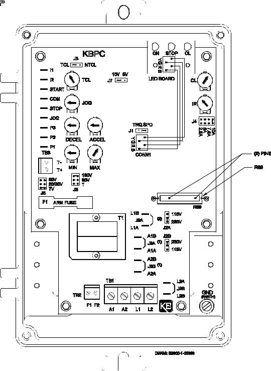
FIG. 1 – CONTROL LAYOUT
(Illustrates Factory Setting of Jumpers and Approximate Trimpot Settings)
3

4
FIG. 2 – MECHANICAL SPECIFICATIONS
INCHES
[mm]
TM
TM
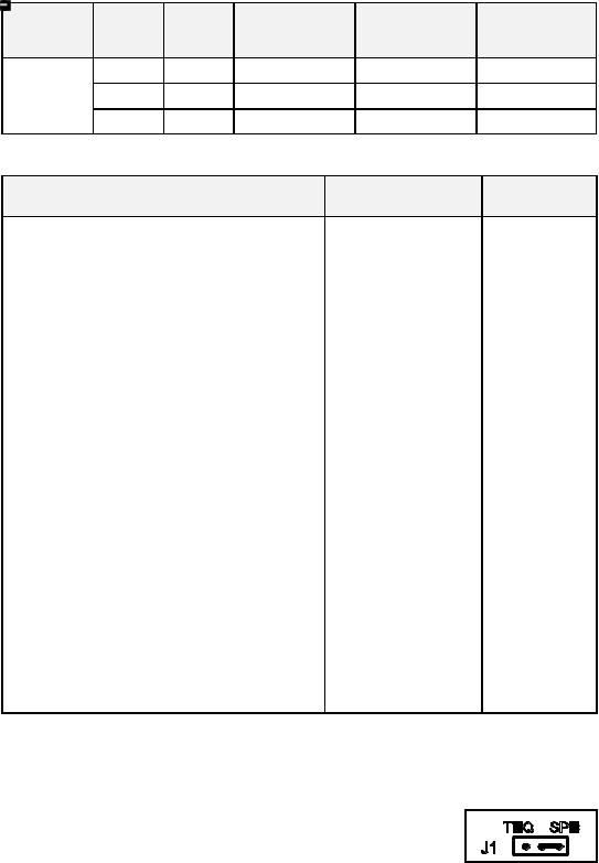
TABLE 1 – ELECTRICAL RATINGS
|
Input |
Max. AC |
Output Voltage |
Max. DC Output |
Max. |
|
Model |
Voltage |
Current |
Horsepower |
|||
(VDC) |
Current (ADC) |
|||||
|
(VAC) |
(ARMS) |
HP, (KW) |
|||
|
|
|
||||
|
115 |
15.0 |
0 – 90 |
10.2 |
1, (.75) |
|
KBPC-240D |
230 |
15.0 |
0 – 180 |
10.2 |
2, (1.5) |
|
|
230 |
15.0 |
0 – 90 |
10.2 |
1, (.75) |
TABLE 2 – GENERAL PERFORMANCE SPECIFICATIONS
Parameter |
|
Specification |
Factory |
|
Setting |
||
|
|
|
|
AC Line Input Voltage (VAC ±10%,50/60 Hz) |
115 or 230 |
230 |
|
AC Line Frequency (Hz), # of Phases |
50/60, 1 |
— |
|
Arm Voltage Range at 115VAC Line (VDC) |
0 |
– 90 |
— |
Arm Voltage Range at 230VAC Line (VDC) |
0 |
– 180, 0 – 90 |
0 – 180 |
Field Voltage at 115VAC Line (VDC) |
100/50 |
— |
|
Field Voltage at 230VAC Line (VDC) |
200/100 |
— |
|
Horsepower Range at 115 VAC HP, (KW) |
1/50 – 1, (.015 – .75) |
— |
|
Horsepower Range at 230 VAC HP, (KW) |
1/25 – 2, (.03 – 1.5) |
— |
|
Ambient Temperature Range (ºC) |
0 |
– 50 |
— |
Speed Range (Ratio) |
50:1 |
— |
|
Arm Feedback Load Regulation (% Base Speed) |
±1 |
— |
|
Tach Feedback Load Regulation (% Set Speed) |
±1 |
— |
|
Line Regulation (% Base Speed) |
±0.5 |
— |
|
Current Ranges (ADC) |
2.5, 5.0, 7.5, 10 |
10 |
|
ACCEL and DECEL Ranges (Sec.) |
0.1 – 15 |
1 |
|
MIN Speed Range (% Base Speed) |
0 |
– 30 |
0 |
MAX Speed Range (% Base Speed) |
60 – 140 |
100 |
|
IR Comp Range at 115VAC Line (VDC) |
0 |
– 15 |
4 |
IR Comp Range at 230VAC Line (VDC) |
0 |
– 30 |
8 |
CL Range (% Range Setting) |
0 |
– 200 |
150 |
Timed CL Range (Sec.) |
0.5 – 15 |
7 |
|
Voltage Following Linearity (% Base Speed) |
±0.5 |
— |
|
II.SETTING SELECTABLE JUMPERS.
The KBPC-240D has customer selectable jumpers which must be set before the control can be used. Bold indicates factory setting. See fig. 1, page 3 for location of jumpers.
A. Control Mode – Speed (SPD) or Torque (TRQ). Note: Factory
setting for J1 is Speed mode. When Jumper J1 is placed in the "SPD" position the drive will control motor speed as a linear
function of the main potentiometer rotation, or analog voltage input. The range of output speed can be adjusted with the MIN
and MAX trimpots. The motor will maintain the preset speed as long as the maximum load does not exceed the current limit set point. If the motor load exceeds the current limit setting, the Overload LED will turn on and the motor will stall.
5
 Loading...