


KBPB & KBCC-R SUPPLEMENTAL INFORMATION
DESCRIPTION
The Anti-Plug Reversing Module used in the KBPB and KBCC-R models has been changed from APRM-2C to APRM-3. The General Performance Specifications of these products have not changed. This supplement is being supplied with the KBPB and KBCC-R Installation and Operation Manuals (Part Nos. A40210A and A40225A) until the new manuals are available.
The figures below replace the figures in the KBPB and KBCC-R Installation and Operation Manuals. For further assistance, contact our Sales Department toll free, at 800-221-6570Φ.
Read Safety Warning
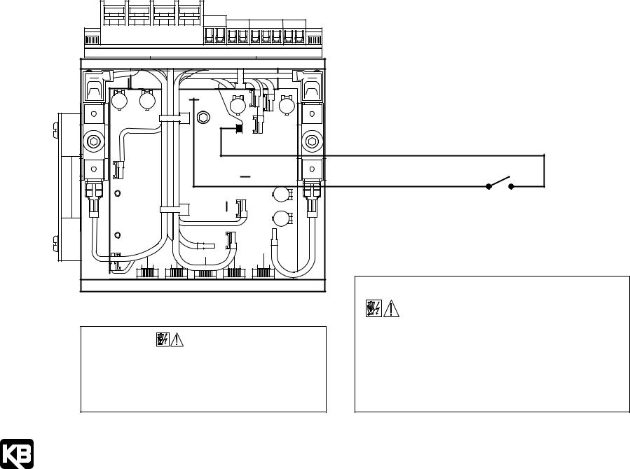
SAFETY WARNING!
This drive contains electronic Start/Stop circuits which can be used to start and stop the drive. However, these circuits are never to be used as safety disconnects since they are not failsafe. Use only the AC line for this purpose. Be sure to follow all instructions carefully. Fire and/or electrocution can result due to improper use of this product.
|
|
Power |
|
|
|
Main Speed Potentiometer |
|
|
Forward-Brake-Reverse Switch |
||||
A2 |
|
|
|
|
|
TB1 |
|
|
|
|
TB1 |
|
|
A1 |
|
|
+ |
- |
S3 S4 |
|
|
|
|
S3 S4 |
FWD-BRK-REV SWITCH |
||
|
|
ARMATURE |
|
|
|
|
|
REV |
|||||
L2 |
|
|
S2 |
|
|
|
|
|
|
||||
|
|
|
|
|
|
S2 |
|
|
|||||
|
|
AC LINE INPUT |
|
|
|
|
|
BRK |
|||||
|
|
|
P2 P3 S1 |
|
|
|
|
P2 P3 S1 |
|
FWD |
|||
L1 |
|
|
|
|
|
|
|
|
|
||||
|
|
|
|
HIGH |
|
|
|
|
|
||||
TB3 |
|
|
WIPER |
|
|
|
|
|
|||||
|
|
LOW |
|
|
|
|
|
||||||
|
|
|
|
|
P1 |
|
|
|
P1 |
|
|
||
|
|
|
|
|
|
MAIN SPEED |
|
|
|
||||
|
CHASSIS |
GROUND |
|
|
|
|
|
|
|
||||
|
|
|
POTENTIOMETER |
|
|
|
|||||||
|
|
(EARTH) |
|
|
|
|
|
|
|
|
|
||
Run-Brake and Forward-Reverse Switches |
Forward-Brake-Reverse Switch with |
Forward-Brake-Reverse and Run-Brake-Jog |
|||||||||||
Adjustable Forward and Preset Reverse Speed |
Switches with Main Speed Potentiometer |
||||||||||||
|
|
|
|
|
|||||||||
|
TB1 |
|
|
|
|
TB1 |
|
|
|
S4 |
TB1 |
|
|
S4 |
|
|
|
|
S4 |
|
|
|
|
FWD-BRK-REV SWITCH |
|||
|
|
|
|
FWD-REV SWITCH |
P1 P2 P3 S1 S2 S3 |
|
|
|
|
P1 P2 P3 S1 S2 S3 |
|||
P2 P3 S1 S2 S3 |
|
|
|
|
|
|
|
REV |
|
||||
|
|
|
REV |
|
|
|
|
|
|||||
|
|
|
|
|
|
|
BRK |
|
|||||
|
|
|
|
FWD |
BRK |
REV |
|
||||||
RUN-BRAKE SWITCH |
|
FWD |
JOG |
||||||||||
FWD |
|
|
|
|
|||||||||
|
|
|
HIGH |
|
|
|
HIGH |
BRK |
|||||
|
|
|
|
FWD-BRK-REV SWITCH |
|||||||||
|
|
|
|
|
|||||||||
|
|
|
|
|
|
RUN |
|||||||
|
|
|
|
WIPER |
|
|
|
WIPER |
|||||
|
|
|
|
|
|
|
RUN-BRK-JOG SWITCH |
||||||
|
|
|
|
LOW |
|
|
|
|
|||||
|
|
|
|
|
|
|
LOW |
|
|||||
|
|
|
|
|
|
|
|
|
|||||
|
|
|
|
MAIN SPEED |
|
|
|
|
|
||||
P1 |
|
|
|
|
|
|
|
|
|
MAIN SPEED |
|
||
|
|
|
|
|
POTENTIOMETER |
|
|
|
|
|
|||
|
|
|
|
|
|
|
|
|
|
POTENTIOMETER |
|
||
|
|
|
|
|
|
|
|
|
|
|
|
||
Forward-Brake-Reverse and Run-Brake-Jog |
|
|
|
Tach-Generator Feedback Connections |
|
||||||||
Switches with Main Speed Potentiometer |
|
|
|
|
|
|
|
|
|||||
|
and Remote Jog Potentiometer |
50 Volts per 1000 RPM Tach-Generator |
7 Volts per 1000 RPM Tach-Generator |
||||||||||
|
TB1 |
|
|
FWD-BRK-REV SWITCH |
|
|
|
|
|
|
|
|
|
S4 |
|
|
|
|
|
|
|
|
|
|
|
||
|
|
|
REV |
|
|
|
|
|
|
|
|
||
S3 |
RUN-BRK-JOG SWITCH |
|
|
|
|
|
|
|
|
||||
BRK |
|
|
|
|
|
|
|
|
|||||
|
|
|
|
|
|
|
|
|
|||||
S2 |
|
|
|
|
|
|
"B" TERMINAL |
|
|
"T" TERMINAL |
|||
|
|
|
FWD |
|
|
|
|
|
|||||
S1 |
RUN |
BRK |
JOG |
|
|
|
|
(ON KBMM) |
|
|
(ON KBMM) |
||
P3 |
HIGH |
|
|
|
|
|
|
|
|
|
|
|
|
WIPER |
|
|
|
|
|
|
|
|
|
|
|
||
P1 P2 |
|
|
|
|
|
|
|
|
TB2 |
|
|
||
LOW |
|
|
|
TB2 |
- |
+ |
|
|
- |
+ |
|||
|
|
|
|
TACH-GENERATOR |
|
TACH-GENERATOR |
|||||||
MAIN SPEED |
|
|
FF+- |
|
|
|
FF+- |
|
|||||
|
|
|
|
|
|
|
|
|
|
|
|||
|
POTENTIOMETER |
|
|
|
|
|
|
|
|
|
|
||
|
REMOTE JOG |
|
|
|
|
|
|
|
|
|
|
||
|
POTENTIOMETER |
|
|
|
|
|
|
|
|
|
|
||
KB ELECTRONICS, INC.
12095 NW 39th Street, Coral Springs, FL 33065-2516 • (954) 346-4900 • FAX (954) 346-3377
Outside Florida Call Toll Free (800) 221-6570 • info@kbelectronics.com |
(A40150) – Rev. C – 7/2006 |
www.kbelectronics.com |
Print Code |
KBPB & KBCC-R SUPPLEMENTAL INFORMATION
|
|
|
|
The latest versions (11/2000) of the KBPB and KBCC-R controls do not contain |
|
|
|
|
|
Inhibit terminals on the terminal block. The Inhibit feature is available, however, |
|
|
|
|
|
by wiring a switch or contact to the I1 and I2 QD terminals on the PC board. |
|
|
|
|
|
The control uses the S2 terminal for brake-to-stop operation (open to stop, |
|
|
|
|
|
close to run). If the application requires coast-to-stop operation, connect the |
|
|
|
|
|
Inhibit Switch as shown below. |
|
|
I2 |
P1 |
P3 |
One side of the Inhibit Switch connects to the new piggyback I1 QD Terminal. |
|
|
|
The other side of the Inhibit Switch connects to the I2 QD Terminal (or the F- |
|||
|
|
|
P2 |
terminal on Terminal Block TB2). It is recommended that the Inhibit Switch wires |
|
|
|
I1 |
|
be routed (and secured with wire ties) with other signal wires (S1, S2, S3, etc.). |
|
|
|
T |
|
|
|
A- |
|
|
|
|
|
|
|
B |
|
Do not route the Inhibit |
Inhibit Switch |
|
|
|
|
||
|
|
F+ |
|
wires with AC line or |
(Close to Coast-to-Stop) |
|
|
|
L1 |
motor wires unless |
(Open to Run) |
|
|
|
|
||
|
A+ |
|
shielded cables are used. |
|
|
F- |
L2 |
|
|
||
|
|
|
|
||
|
|
|
|
MOUNTING INSTRUCTION FOR CHASSIS & IP-20 CONTROLS |
|
Note: KBPB shown. The KBCC-R uses the same PC board. |
WARNING! This control must be mounted in an enclosure. Care |
|
|
should be taken to avoid extreme hazardous locations where |
|
|
physical damage to the control can occur due to moisture, metal chips, dust, |
|
SAFETY WARNING! |
and other contamination including corrosive atmosphere. If such contamination |
|
This drive contains electronic Start/Stop circuits which can be used to |
is present, special enclosures may be required such as NEMA type 4X. Failure |
|
to observe these instructions could cause an electrical shock, fire, or explosion |
||
start and stop the drive. However, these circuits are never to be used |
||
in this product or the products used with this product. Do not use this control |
||
as safety disconnects since they are not fail-safe. Use only the AC |
||
in an explosion-proof application. You must read the Safety Warning which |
||
line for this purpose. Be sure to follow all instructions carefully. Fire |
||
accompanies this product. |
||
and/or electrocution can result due to improper use of this product. |
||
|
KB ELECTRONICS, INC.
12095 NW 39th Street, Coral Springs, FL 33065-2516 • (954) 346-4900 • FAX (954) 346-3377 |
|
Outside Florida Call Toll Free (800) 221-6570 • info@kbelectronics.com |
(A40150) – Rev. C – 7/2006 |
www.kbelectronics.com |
Print Code |


 Loading...