


 Loading...
Ninja ZX-6R
Motorcycle
Assembly & Preparation
Manual
Foreword
In order to ship Kawasaki vehicles as efficiently as possible, they are partially disassembled before crating. Since some of the most commonly removed parts have a direct bearing on a vehicle’s reliability and safety, conscientious pre-sale assembly and preparation becomes extremely important. Good setup procedures can prevent needless warranty claims and give customers a greater sense of confidence in Kawasaki and their Kawasaki Dealers.
This Assembly and Preparation Manual explains step by step procedures of the following items for all Kawasaki motorcycles.
1.Uncrating
2.Assembly
3.Preparation
The selling dealer assumes sole responsibility for any unauthorized modifications prior to sale. Refer to your Service Binder for any Service Bulletins specifying Factory Directed Modifications (Special Claims) which must be performed before the vehicle is ready for sale.
Whenever you see the following symbols heed their instructions! Always follow safe operating and maintenance practices.
 WARNING
This warning symbol identifies special instructions or procedures which, if not correctly followed, could result in personal injury, or less of life.
CAUTION
This caution symbol identifies special instructions or procedures which, if not correctly followed, could result in damage to, or destruction of equipment.
NOTE
○This note symbol indicates points of particular interest for more efficient and convenient operation.
Kawasaki Heavy Industries, Ltd. accepts no liability for any inaccuracies or omissions in this publication, although every possible measure has been taken to make it as complete and accurate as possible. All procedures and specifications subject to change without notice.
© 2004 Kawasaki Heavy Industries, Ltd. |
Sep. 2004 (K) |
Table of Contents |
|
Uncrating ...................................................................................... |
3 |
Opening Crate ............................................................................. |
3 |
Parts Check................................................................................. |
4 |
Assembly ...................................................................................... |
4 |
Steering Stem Head Nut ............................................................. |
4 |
Clutch Cable................................................................................ |
5 |
Windshield................................................................................... |
5 |
Rider’s Seat Bolt.......................................................................... |
5 |
Brake Disc Cleaning.................................................................... |
5 |
Preparation ................................................................................... |
6 |
Battery Service ............................................................................ |
6 |
Front Brake Fluid......................................................................... |
13 |
Rear Brake Fluid ......................................................................... |
15 |
Clutch Lever and Cable............................................................... |
17 |
Drive Chain.................................................................................. |
17 |
Front Fork.................................................................................... |
19 |
Rear Shock Absorber .................................................................. |
20 |
Tire Air Pressures........................................................................ |
21 |
Fuel ............................................................................................. |
21 |
Coolant ........................................................................................ |
21 |
Engine Oil (4-stroke) ................................................................... |
23 |
Throttle Grip and Cable ............................................................... |
24 |
Rear Brake Light Switch.............................................................. |
24 |
Idle Speed Adjustment ................................................................ |
25 |
Headlight Aim .............................................................................. |
25 |
Digital Meter ................................................................................ |
25 |
Fastener Check ........................................................................... |
28 |
Standard Torque Table ................................................................ |
30 |
Test Ride the Motorcycle ............................................................. |
30 |
A & P Check List ......................................................................... |
30 |

Uncrating
Opening Crate
•Clear a space about 6 m (20 ft) square to give yourself plenty of space to work.
•Place the crate upright on its base.
•Remove the cardboard cover.
•Remove the parts box.
CAUTION
When you remove the crate bracket from the motorcycle, be careful not to drop any parts and bracket onto the fuel tank and other components, and not to scratch the fuel tank by the crate bracket. This could damage the fuel tank or components.
•First, remove the lower crate bolt (D = 22) at the steering stem and discard it.
•Remove the upper crate bolts (D = 8) to take off the crate bracket and foam pad and discard them.
A.Lower Crate Bolt (D = 22)
B.Upper Crate Bolts (D = 8)
C.Crate Bracket
D.Foam Pad
•Take out all the bolts and screws and remove the top and sides of the crate.
•Lift the vehicle upward about 10 cm (4 in.) and remove the two lower support brackets. Roll the vehicle off the crate base.
UNCRATING 3
A. Lower Support Bracket
4 ASSEMBLY
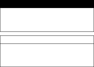
Parts Check
•Open the parts box, and check the parts against the illustrations. There may be minor differences between these illustrations and the actual vehicle parts. In the following charts under Remarks, D = diameter in millimeters, and L = length in millimeters.
|
|
|
|
|
|
|
|
|
|
|
|
No. |
Part Name |
Qty |
Remarks |
|
|
1 |
Steering Stem Head Nut |
1 |
D = 28 |
|
|
2 |
Plastic Washer |
6 |
D = 5.3 × 11.5 |
|
|
|
Socket Bolt |
6 |
D = 5, L = 16 |
|
|
|
Wellnut |
6 |
D = 5 |
|
|
|
Windshield |
1 |
|
|
|
3 |
Socket Bolt, Rider’s Seat |
2 |
D = 6, L = 16.3 |
|
|
4 |
Battery Electrolyte, YTX9-BS |
1 |
12 V 8 Ah |
|
|
5 |
Owner’s Manual |
1 |
|
|
|
Assembly
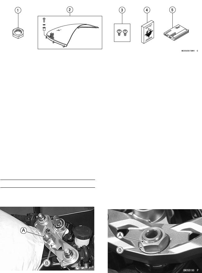
Steering Stem Head Nut
•Remove the steering stem head dummy nut and discard it. Do not remove the steering stem flat washer under the dummy nut.
•Remove the non-permanent locking agent and clean the steering stem shaft threads.
•Install the steering stem head nut (D = 28) on the flat washer with the chamfered side facing upwards and tighten it to the specified torque.
Torque: 78 N·m (8.0 kgf·m, 58 ft·lb)
|
|
|
|
|
|
|
|
A. Dummy Nut |
|
||
A. Chamfered Side of Stem Head Nut |
|||
B. Flat Washer |
|||
B. Flat Washer |
|||
|
|
||

Clutch Cable
•Applycable.a light coat of grease on the clutch inner
•Line up the slots on the clutch lever and adjuster.
•Fit the tip of the clutch inner cable into the lever socket, slide the inner cable through the slots, and release the outer cable into the adjuster.
A.Clutch Cable
B.Adjuster
C.Cable Tip
D.Clutch Lever
Windshield
•Fit the six wellnuts (D = 5) into the holes in the edge of the windshield from the outside with their flanges out.
A.Windshield
B.Wellnuts
•Put the front tab into the slot of the upper fairing.
ASSEMBLY 5
A.Front Tab
B.Slot
C.Upper Fairing
•Install the six plastic washers and the socket bolts (D = 5, L = 16) on the upper fairing.
A.Plastic Washers and Socket Bolts
B.Windshield
•Tighten the windshield bolts. Do not over tighten the windshield bolts.
Rider’s Seat Bolt
•Install the rider’s seat bolts. See “Battery Service” section.
Brake Disc Cleaning
•Clean the front and rear brake discs using oilless solvent.
 WARNING
If not removed, the anticorrosive treatment applied to the brake disc surface will interfere with brake action, and an unsafe riding condition could result.
6 PREPARATION
Preparation
Battery Service
Rider’s Seat Removal
•Unscrew the left and right side cover bolts (D = 6) (3) and remove the covers by pulling them outward to clear the projections.
A.Left Side Cover
B.Bolts (D = 6)
C.Projections
A.Right Side Cover
B.Bolt (D = 6)
C.Projection
•Remove the rider’s seat by pulling the front of it up and forward.
A. Rider’s Seat
The battery used in this motorcycle is a sealed type and never needs to be refilled. Follow the procedure for activating a new battery to ensure the best possible battery performance.
Activating the battery requires two steps, filling the battery with electrolyte, and charging. Read the electrolyte safety label and the following procedures carefully before battery activation.
CAUTION
Incorrect Battery Activation will reduce battery performance and service life. Be sure to strictly follow the Battery Service instructions in this Manual.
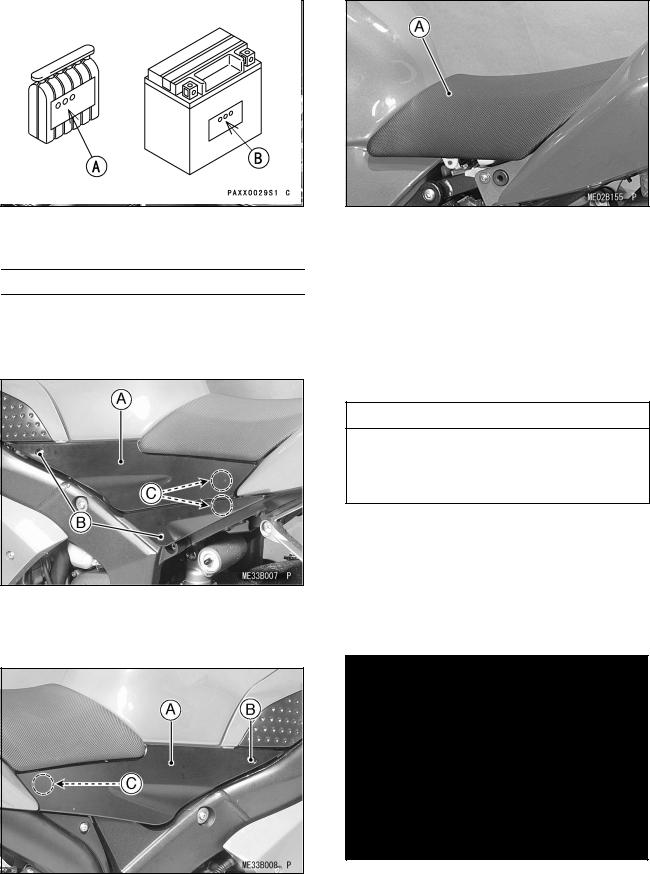
•Make sure to use the electrolyte packed in the crate with the unit.
•Make sure that the model name of the electrolyte container matches the model name of the battery. These names must be the same.
Battery Model Name for
ZX636-C1: YTX9-BS
A.Model Name of the Electrolyte
B.Model Name of the Battery
CAUTION
Sealed battery electrolyte has a higher concentration of sulfuric acid. Each container contains the proper amount of electrolyte for its specific battery. Insufficient or incorrect electrolyte will reduce battery performance and service life. Electrolyte over capacity can lead to battery cracking or leaking and result in corrosion damage to the vehicle.
Battery Removal
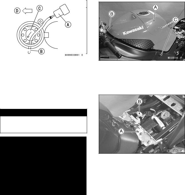
•Check for fuel in the fuel tank.
•If fuel remains in the fuel tank, do the following procedures.
•Draw the fuel out from the fuel tank with a commercially available pump.
•Use a soft plastic hose as a pump inlet hose in order to insert the hose smoothly.
•Put the hose through the filler opening into the tank and draw the fuel out.
 WARNING
The fuel could not be removed completely from the fuel tank. Be careful for remained fuel spillage.
A.Commercially Available Pump
B.Soft Plastic Hose
C.Filler Opening
D.Front
•Remove the fuel tank bolts (D = 6, D = 8) (3).
PREPARATION 7
A.Fuel Tank
B.Fuel Tank Bolt (D = 6)
C.Fuel Tank Bolts (D = 8)
•Remove the fuel tank pivot bolt (D = 6).
•Disconnect the fuel pump connector (4P).
A.Fuel Tank Pivot Bolt (D = 6)
B.Fuel Pump Connector (4P)
•Open the fuel tank cap to lower the pressure in the tank.
NOTE
○During tank removal, keep the tank cap open to release pressure in the tank. This reduces fuel spillage.
•Be sure to place a piece of cloth around the fuel hose joint.
•Push the joint lock claws.
8 PREPARATION
A.Fuel Hose Joint
B.Joint Lock Claws
•Pull the joint lock.
•Pull the fuel hose joint out of the delivery pipe.
 WARNING
Be prepared for fuel spillage; any spilled fuel must be completely wiped up immediately.
When the fuel hose is disconnected, fuel spills out from the hose and the pipe because of residual pressure. Cover the hose connection with a piece of clean cloth to prevent fuel spillage.
A.Joint Lock
B.Fuel Hose Joint
•Remove the drain hose from the fuel tank.
A.Fuel Tank
B.Drain Hose
•Close the fuel tank cap.
•Removesurface. the fuel tank, and place it on a flat
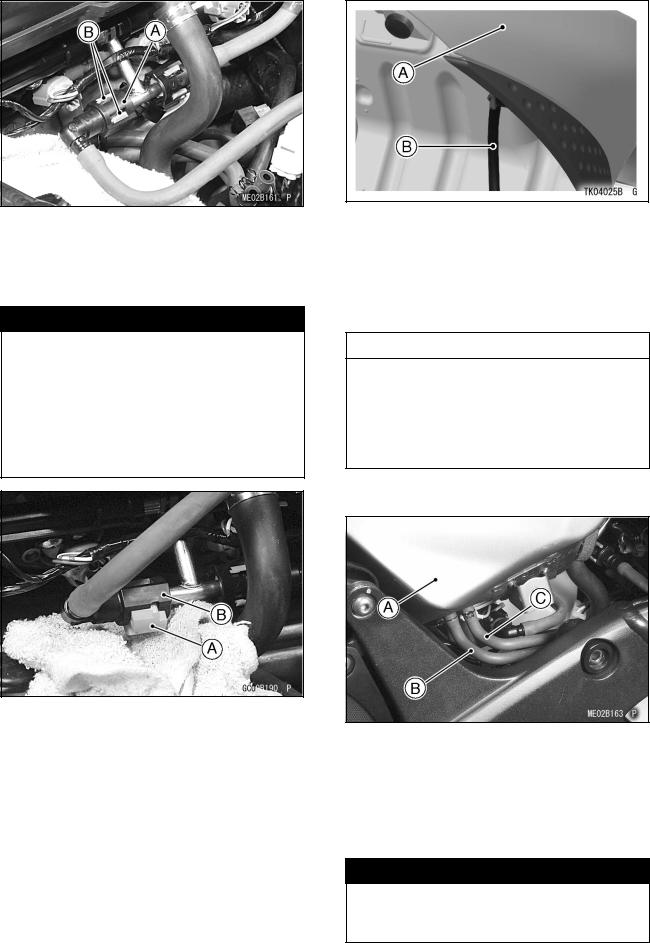
•For California Model, note the following.
CAUTION
For California model, if gasoline, solvent, water or any other liquid enters the canister, the canister’s vapor absorbing capacity is greatly reduced. If the canister does become contaminated, replace it with a new one.
•Remove the fuel return hose (red) and breather hose (blue) from the fuel tank.
A.Fuel Tank
B.Fuel Return Hose (Red)
C.Breather Hose (Blue)
•Be sure to plug the evaporative fuel return hose to prevent fuel spilling before fuel tank removal.
 WARNING
For California model, be careful not to spill the gasoline through the return hose. Spilled fuel is hazardous.
•If liquid or gasoline flows into the breather hose, remove the hose and blow it clean with compressed air.
•Be careful of fuel spillage from the fuel tank since fuel still remains in the fuel tank and fuel pump.
 WARNING
Store the fuel tank in an area which is well-ventilated and free from any source of flame or sparks. Do not smoke in this area. Place the fuel tank on a flat surface and plug the fuel pipes to prevent fuel leakage.
•Remove the fuel tank bracket bolts.
•Remove the left seat cover bolt (D = 6) (1) and right seat cover bolts (D = 6) (2).
A.Fuel Tank Bracket Bolts (D = 6)
B.Seat Cover Bolts (D = 6)
C.Battery
•Take the battery out of the battery case.
Battery Specifications
Make |
Yuasa |
Battery Type |
YTX9-BS |
Battery Capacity |
12 V 8 Ah |
Electrolyte Capacity |
0.40 L |
Battery/Electrolyte Set P/No. |
26012-1326 |
Battery Activation
Filling the Battery with Electrolyte
CAUTION
Do not remove the aluminum sealing sheet [A] from the filler ports [B] until just prior to use. Be sure to use the dedicated electrolyte container for correct electrolyte volume.
PREPARATION 9
•Place the battery on a level surface.
•Check to see that the sealing sheet has no peeling, tears, or holes in it.
•Remove the sealing sheet.
NOTE
○The battery is vacuum sealed. If the sealing sheet has leaked air into the battery, it may require a longer initial charge.
•Remove the electrolyte container from the vinyl bag.
•Detach the strip of caps [A] from the container and set aside, these will be used later to seal the battery.
NOTE
○Do not pierce or otherwise open the sealed cells [B] of the electrolyte container. Do not attempt to separate individual cells.
•Place the electrolyte container upside down with the six sealed cells into the filler ports of the battery. Hold the container level, push down to break the seals of all six cells. You will see air bubbles rising into each cell as the ports fill.
NOTE
○Do not tilt the electrolyte container.
Loading...