


VULCAN 1500 MEAN STREAK
VN1500 MEAN STREAK
Motorcycle
Service Manual
All rights reserved. No parts of this publication may be reproduced, stored in a retrieval system, or transmitted in any form or by any means, electronic mechanical photocopying, recording or otherwise, without the prior written permission of Quality Assurance Department/Consumer Products & Machinery Company/Kawasaki Heavy Industries, Ltd., Japan.
No liability can be accepted for any inaccuracies or omissions in this publication, although every possible care has been taken to make it as complete and accurate as possible.
The right is reserved to make changes at any time without prior notice and without incurring an obligation to make such changes to products manufactured previously. See your Motorcycle dealer for the latest information on product improvements incorporated after this publication.
All information contained in this publication is based on the latest product information available at the time of publication. Illustrations and photographs in this publication are intended for reference use only and may not depict actual model component parts.
© Kawasaki Heavy Industries, Ltd., 2001 |
First Edition (1) : Jul. 15, 2001 (M) |
LIST OF ABBREVIATIONS
A |
ampere(s) |
lb |
pound(s) |
ABDC |
after bottom dead center |
m |
meter(s) |
AC |
alternating current |
min |
minute(s) |
ATDC |
after top dead center |
N |
newton(s) |
BBDC |
before bottom dead center |
Pa |
pascal(s) |
BDC |
bottom dead center |
PS |
horsepower |
BTDC |
before top dead center |
psi |
pound(s) per square inch |
C |
degree(s) Celsius |
r |
revolution |
DC |
direct current |
r/min, rpm |
revolution(s) per minute |
F |
farad(s) |
TDC |
top dead center |
F |
degree(s) Fahrenheit |
TIR |
total indicator reading |
ft |
foot, feet |
V |
volt(s) |
g |
gram(s) |
W |
watt(s) |
h |
hour(s) |
|
ohm(s) |
L |
liter(s) |
|
|
Read OWNER’S MANUAL before operating.

EMISSION CONTROL INFORMATION
To protect the environment in which we all live, Kawasaki has incorporated crankcase emission (1) and exhaust emission
(2) control systems in compliance with applicable regulations of the United States Environmental Protection Agency and California Air Resources Board. Additionally, Kawasaki has incorporated an evaporative emission control system (3) in compliance with applicable regulations of the California Air Resources Board on vehicles sold in California only.
1. Crankcase Emission Control System
This system eliminates the release of cranckcase vapors into the atmosphere. Instead, the vapors are routed through an oil separator to the inlet side of the engine. While the engine is operating, the vapors are drawn into combustion chamber, where they are burned along with the fuel and air supplied by the fuel injection system.
2. Exhaust Emission Control System
This system reduces the amount of pollutants discharged into the atmosphere by the exhaust of this motorcycle. The fuel, ignition, and exhaust systems of this motorcycle have been carefully designed and constructed to ensure an efficient engine with low exhaust pollutant levels.
The exhaust system of this model motorcycle manufactured primarily for sale in California includes a catalytic converter system.
3. Evaporative Emission Control System
Vapors caused by fuel evaporation in the fuel system are not vented into the atmosphere. Instead, fuel vapors are routed into the running engine to be burned, or stored in a canister when the engine is stopped. Liquid fuel is caught by a vapor separator and returned to the fuel tank.
The Clean Air Act, which is the Federal law covering motor vehicle pollution, contains what is commonly referred to as the Act’s "tampering provisions."
"Sec. 203(a) The following acts and the causing thereof are prohibited...
(3)(A) for any person to remove or render inoperative any device or element of design installed on or in a motor vehicle or motor vehicle engine in compliance with regulations under this title prior to its sale and delivery to the ultimate purchaser, or for any manufacturer or dealer knowingly to remove or render inoperative any such device or element of design after such sale and delivery to the ultimate purchaser.
(3)(B) for any person engaged in the business of repairing, servicing, selling, leasing, or trading motor vehicles or motor vehicle engines, or who operates a fleet of motor vehicles knowingly to remove or render inoperative any device or element of design installed on or in a motor vehicle or motor vehicle engine in compliance with regulations under this title following its sale and delivery to the ultimate purchaser..."
NOTE
The phrase "remove or render inoperative any device or element of design" has been generally interpreted as follows:
1.Tampering does not include the temporary removal or rendering inoperative of devices or elements of design in order to perform maintenance.
2.Tampering could include:
a.Maladjustment of vehicle components such that the emission standards are exceeded.
b.Use of replacement parts or accessories which adversely affect the performance or durability of the motorcycle.
c.Addition of components or accessories that result in the vehicle exceeding the standards.
d.Permanently removing, disconnecting, or rendering inoperative any component or element of design of the emission control systems.
WE RECOMMEND THAT ALL DEALERS OBSERVE THESE PROVISIONS OF FEDERAL LAW, THE VIOLATION OF WHICH IS PUNISHABLE BY CIVIL PENALTIES NOT EXCEEDING $10,000 PER VIOLATION.

TAMPERING WITH NOISE CONTROL SYSTEM PROHIBITED
Federal law prohibits the following acts or the causing thereof: (1) The removal or rendering inoperative by any person other than for purposes of maintenance, repair, or replacement, of any device or element of design incorporated into any new vehicle for the purpose of noise control prior to its sale or delivery to the ultimate purchaser or while it is in use, or (2) the use of the vehicle after such device or element of design has been removed or rendered inoperative by any person.
Among those acts presumed to constitute tampering are the acts listed below:
•Replacement of the original exhaust system or muffler with a component not in compliance with Federal regulations.
•Removal of the muffler(s) or any internal portion of the muffler(s).
•Removal of the air box or air box cover.
•Modifications to the muffler(s) or air inlet system by cutting, drilling, or other means if such modifications result in increased noise levels.
Foreword
This manual is designed primarily for use by trained mechanics in a properly equipped shop. However, it contains enough detail and basic information to make it useful to the owner who desires to perform his own basic maintenance and repair work. A basic knowledge of mechanics, the proper use of tools, and workshop procedures must be understood in order to carry out maintenance and repair satisfactorily. Whenever the owner has insufficient experience or doubts his ability to do the work, all adjustments, maintenance, and repair should be carried out only by qualified mechanics.
In order to perform the work efficiently and to avoid costly mistakes, read the text, thoroughly familiarize yourself with the procedures before starting work, and then do the work carefully in a clean area. Whenever special tools or equipment are specified, do not use makeshift tools or equipment. Precision measurements can only be made if the proper instruments are used, and the use of substitute tools may adversely affect safe operation.
For the duration of the warranty period, we recommend that all repairs and scheduled maintenance be performed in accordance with this service manual. Any owner maintenance or repair procedure not performed in accordance with this manual may void the warranty.
To get the longest life out of your vehicle:
•Follow the Periodic Maintenance Chart in the Service Manual.
•Be alert for problems and non-scheduled maintenance.
•Use proper tools and genuine Kawasaki Motorcycle parts. Special tools, gauges, and testers that are necessary when servicing Kawasaki motorcycles are introduced by the Special Tool Catalog or Manual. Genuine parts provided as spare parts are listed in the Parts Catalog.
•Follow the procedures in this manual carefully. Don’t take shortcuts.
•Remember to keep complete records of maintenance and repair with dates and any new parts installed.
How to Use This Manual
In preparing this manual, we divided the product into its major systems. These systems became the manual’s chapters.
The Quick Reference Guide shows you all of the product’s system and assists in locating their chapters.
Each chapter in turn has its own comprehensive Table of Contents.
If you want ignition coil information, for example, use the Quick Reference Guide to locate the Electrical System chapter. Then, use the Table of Contents on the first page of the chapter to find the Ignition Coil section.
Whenever you see these WARNING and CAUTION symbols, heed their instructions! Always follow safe operating and maintenance practices.
This warning symbol identifies special instructions or procedures which, if not correctly followed, could result in personal injury, or loss of life.
CAUTION
This caution symbol identifies special instructions or procedures which, if not strictly observed, could result in damage to or destruction of equipment.
This manual contains four more symbols (in addition to WARNING and CAUTION) which will help you distinguish different types of information.
NOTE
This note symbol indicates points of particular interest for more efficient and convenient operation.
• Indicates a procedural step or work to be done.
Indicates a procedural sub-step or how to do the work of the procedural step it follows. It also precedes the text of a NOTE.
 Indicates a conditional step or what action to take based on the results of the test or inspection in the procedural step or sub-step it follows.
In most chapters an exploded view illustration of the system components follows the Table of Contents. In these illustrations you will find the instructions indicating which parts require specified tightening torque, oil, grease or a locking agent during assembly.

GENERAL INFORMATION 1-1
1
General Information
Table of Contents
Before Servicing................................................................................................................................................................ |
1-2 |
Model Identification........................................................................................................................................................... |
1-4 |
General Specifications ...................................................................................................................................................... |
1-6 |
Torque and Locking Agent................................................................................................................................................ |
1-8 |
Special Tools and Sealant............................................................................................................................................... |
1-13 |
Cable, Wire, and Hose Routing...................................................................................................................................... |
1-20 |

1-2 GENERAL INFORMATION
Before Servicing
Before starting to service a motorcycle, careful reading of the applicable section is recommended to eliminate unnecessary work. Photographs, diagrams, notes, cautions, warnings, and detailed descriptions have been included wherever necessary. Nevertheless, even a detailed account has limitations, a certain amount of basic knowledge is also required for successful work.
Especially note the following:
(1) Dirt
Before removal and disassembly, clean the motorcycle. Any dirt entering the engine or other parts will work as an abrasive and shorten the life of the motorcycle. For the same reason, before installing a new part, clean off any dust or metal filings.
(2) Battery Leads
Disconnect the ground (− ) lead from the battery before performing any disassembly operations on the motorcycle. This prevents the engine from accidentally turning over while work is being carried out, sparks from being generated while disconnecting the wires from electrical parts, as well as damage to the electrical parts themselves. For reinstallation, first connect the positive lead to the positive (+) terminal of the battery.
(3) Installation, Assembly
Generally, installation or assembly is the reverse of removal or disassembly. But if this Service Manual has installation or assembly procedures, follow them. Note parts locations and cable, wire, and hose routing during removal or disassembly so they can be installed or assembled in the same way. It is preferable to mark and record the locations and routing as much as possible.
(4) Tightening Sequence
Generally, when installing a part with several bolts, nuts, or screws, start them all in their holes and tighten them to a snug fit. Then tighten them evenly in a cross pattern. This is to avoid distortion of the part and/or causing gas or oil leakage. Conversely when loosening the bolts, nuts, or screws, first loosen all of them by about a quarter turn and then remove them. Where there is a tightening sequence indication in this Service Manual, the bolts, nuts, or screws must be tightened in the order and method indicated.
(5) Torque
When torque values are given in this Service Manual, use them. Either too little or too much torque may lead to serious damage. Use a good quality, reliable torque wrench.
(6) Force
Common sense should dictate how much force is necessary in assembly and disassembly. If a part seems especially difficult to remove or install, stop and examine what may be causing the problem. Whenever tapping is necessary, tap lightly using a wooden or plastic-faced mallet. Use an impact driver for screws (particularly for the removal of screws held by a locking agent) in order to avoid damaging the screw heads.
(7) Edges
Watch for sharp edges, especially during major engine disassembly and assembly. Protect your hands with gloves or a piece of thick cloth when lifting the engine or turning it over.
(8) High-Flash Point Solvent
A high-flash point solvent is recommended to reduce fire danger. A commercial solvent commonly available in North America is Stoddard solvent (generic name). Always follow manufacturer and container directions regarding the use of any solvent.
(9) Gasket, O-Ring
Do not reuse a gasket or O-ring once it has been in service. The mating surfaces around the gasket should be free of foreign matter and perfectly smooth to avoid oil or compression leakage.
(10) Liquid Gasket, Non-Permanent Locking Agent
Follow manufacturer’s directions for cleaning and preparing surfaces where these compounds will be used. Apply sparingly. Excessive amounts may block engine oil passages and cause serious damage. An example of a nonpermanent locking agent commonly available in North America is Loctite Lock’n Seal (Blue).
(11) Press
A part installed using a press or driver, such as a wheel bearing, should first be coated with oil on its outer or inner circumference so that it will go into place smoothly.
(12) Ball Bearing and Needle Bearing
Do not remove a ball bearing or a needle bearing unless it is absolutely necessary. Replace any ball or needle bearings that were removed with new ones, as removal generally damages bearings. Install bearings with the marked side facing out applying pressure evenly with a suitable driver. Only press on the race that forms the press fit with the base component to avoid damaging the bearings. This prevents severe stress on the balls or needles and races, and prevent races and balls or needles from being dented. Press a ball bearing until it stops at the stopper in the hole or on the shaft.
(13) Oil Seal and Grease Seal
Replace any oil or grease seals that were removed with new ones, as removal generally damages seals. When pressing in a seal which has manufacturer’s marks, press it in with the marks facing out. Seals should be pressed into place using a suitable driver, which contacts evenly with the side of seal, until the face of the seal is even with the end of the hole. Before a shaft passes through a seal, apply a little high temperature grease on the lips to reduce rubber to metal friction.
GENERAL INFORMATION 1-3
Before Servicing
(14) Circlip, Retaining Ring, and Cotter Pin
Replace any circlips and retaining rings, and cotter pins that were removed with new ones, as removal weakens and deforms them. When installing circlips and retaining rings, take care to compress or expand them only enough to install them and no more.
(15) Lubrication
Engine wear is generally at its maximum while the engine is warming up and before all the rubbing surfaces have an adequate lubricative film. During assembly, oil or grease (whichever is more suitable) should be applied to any rubbing surface which has lost its lubricative film. Old grease and dirty oil should be cleaned off. Deteriorated grease has lost its lubricative quality and may contain abrasive foreign particles.
Don’t use just any oil or grease. Some oils and greases in particular should be used only in certain applications and may be harmful if used in an application for which they are not intended. This manual makes reference to molybdenum disulfide grease (MoS2) and molybdenum disulfide oil in the assembly of certain engine and chassis parts. The molybdenum disulfide oil is a mixture of engine oil and molybdenum disulfide grease with a weight ratio (10 : 1), which can be made in your work shop. Always check manufacturer recommendations before using such special lubricants.
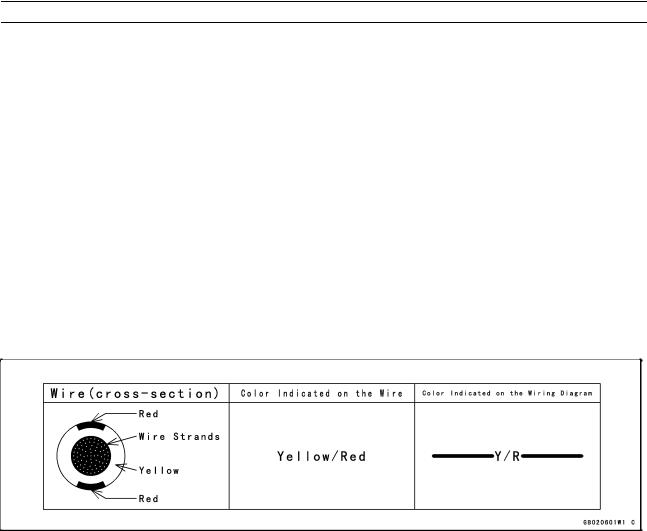
(16) Electrical Wires
All the electrical wires are either single-color or two-color and, with only a few exceptions, must be connected to wires of the same color. On any of the two-color wires there is a greater amount of one color and a lesser amount of a second color, so a two-color wire is identified by first the primary color and then the secondary color. For example, a yellow wire with thin red stripes is referred to as a "yellow/red" wire; it would be a "red/yellow" wire if the colors were reversed to make red the main color.
(17) |
Replacement Parts |
|
|
|
|
When there is a replacement instruction, replace these parts with new ones every time they are removed. These |
|||
|
replacement parts will be damaged or lose their original function once removed. |
|
||
(18) |
Inspection |
|
|
|
|
When parts have been disassembled, visually inspect these parts for the following conditions or other damage. If |
|||
|
there is any doubt as to the condition of them, replace them with new ones. |
|
||
|
Abrasion |
Crack |
Hardening |
Warp |
|
Bent |
Dent |
Scratch |
Wear |
|
Color change |
Deterioration |
Seizure |
|
(19) Specifications
Specification terms are defined as follows:
"Standards" show dimensions or performances which brand-new parts or systems have.
"Service Limits" indicate the usable limits. If the measurement shows excessive wear or deteriorated performance, replace the damaged parts.
1-4 GENERAL INFORMATION
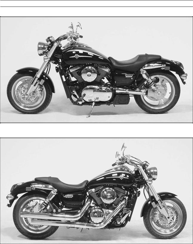
Model Identification
VN1500-P1 (US, and Canada) Left Side View:
VN1500-P1 (US, and Canada) Right Side View:
GENERAL INFORMATION 1-5
Model Identification
VN1500-P1 (Europe) Left Side View:
VN1500-P1 (Europe) Right Side View:

1-6 GENERAL INFORMATION
General Specifications
Items |
|
VN1500-P1 |
Dimensions: |
|
|
Overall length |
|
2410 mm (94.9 in.) |
Overall width |
|
850 mm (33.5 in.) |
Overall height |
|
1100 mm (43.3 in.) |
Wheelbase |
|
1705 mm (67.1 in.) |
Road clearance |
|
125 mm (4.92 in.) |
Seat height |
|
700 mm (27.6 in.) |
Dry mass |
|
289 kg (637 lb) |
Curb mass: |
Front |
144 kg (318 lb) |
|
Rear |
172 kg (379 lb) |
Fuel tank capacity |
|
17.0 L (4.49 US gal) |
Fuel |
|
Unleaded and high-octane gasoline (see VN1500-P1 Owner’s Manual) |
Performance: |
|
|
Minimum turning radius |
3.1 m (10.2 ft) |
|
Engine: |
|
|
Type |
|
4-stroke, SOHC, V2-cylinder |
Cooling system |
|
Liquid-cooled |
Bore and stroke |
|
102 2 90 mm (4.02 2 3.54 in.) |
Displacement |
|
1470 mL (89.70 cu in.) |
Compression ratio |
|
9.0 : 1 |
Maximum horsepower |
|
53 kW (72 PS) @5500 r/min (rpm), |
|
|
(AU) 47 kW (64 PS) @ 5300 r/min (rpm), (CA) (CN) (US) – |
Maximum torque |
|
114 N1m (11.6 kg1m, 84.1 ft1lb) @3000 r/min (rpm), |
|
|
(AU) 108 N1m (11.0 kg1m, 79.7 ft1lb) @3000 r/min (rpm), (CA) (CN) (US) – |
Carburetion system |
|
DFI (Digital Fuel Injection) System |
Starting system |
|
Electric starter |
Ignition system |
|
Battery and coil (transistorized) |
Timing advance |
|
Electronically advanced (digital) |
Ignition timing |
|
From 5 BTDC @950 r/min (rpm) 25 BTDC @4500 r/min (rpm) |
Spark plugs |
|
NGK DPR6EA-9 or ND X20EPR-U9 |
Cylinder numbering method |
Front to Rear, 1-2 |
|
Firing order |
|
1-2 |
Valve timing: |
|
|
Inlet |
Open |
28 BTDC |
|
Close |
72 ABDC |
|
Duration |
280 |
Exhaust |
Open |
66 BBDC |
|
Close |
42 ATDC |
|
Duration |
288 |
Lubrication system |
|
Forced lubrication (wet sump) |
Engine oil: |
Type |
API : SE, SF or SG class |
|
|
API SH or SJ class with JASO MA |
|
Viscosity |
SAE10W-40 |
|
Capacity |
3.5 L (3.7US qt, when engine is completely disassembled and dry) |
Drive Train: |
|
|
Primary reduction system: |
|
|
Type |
|
Gear |
Reduction ratio |
|
1.517 (85/56) |
Clutch type |
|
Wet multi disc |
|
|
|
GENERAL INFORMATION 1-7 |
General Specifications |
|
|
|
|
|
|
|
|
|
|
|
Items |
|
|
VN1500-P1 |
Transmission: |
|
|
|
Type |
|
5-speed, constant mesh, return shift |
|
Gear ratios: |
|
(CA, CN, US) |
|
|
1st |
2.500 |
(40/16) |
|
2nd |
1.750 |
(35/20) |
|
3rd |
1.333 |
(32/24) |
|
4th |
1.074 |
(29/27) |
|
5th |
0.867 |
(26/30) |
|
|
(other than CA, CN, US) |
|
|
1st |
2.500 |
(40/16) |
|
2nd |
1.590 |
(35/22) |
|
3rd |
1.192 |
(31/26) |
|
4th |
0.965 |
(28/29) |
|
5th |
0.781 |
(25/32) |
Final drive system: |
|
|
|
Type |
|
Shaft |
|
Reduction ratio |
|
2.619 |
(15/21 2 33/9) |
Overall drive ratio |
|
(CA, CN, US) 3.445 @ Top gear |
|
|
|
(other than CA, CN, US) 3.105 @ Top gear |
|
Final gear case oil: |
|
|
|
Grade |
|
API Service Classification: GL-5 Hypoid gear oil |
|
Viscosity |
|
SAE90 (above 5 C), SAE80 (below 5 C) |
|
Capacity |
|
200 mL |
|
Frame: |
|
|
|
Type |
|
Tubular, double cradle |
|
Caster (rake angel) |
|
32 |
|
Trail |
|
144 mm (5.67 in.) |
|
Front tire: |
Type |
Tubeless |
|
|
Size |
130/70R17 M/C 62H |
|
Rear tire: |
Type |
Tubeless |
|
|
Size |
170/60R17 M/C 72H |
|
Front suspension: |
Type |
Telescopic fork (upside-down) |
|
|
Wheel travel |
150 mm (5.91 in.) |
|
Rear suspension: |
Type |
Swingarm, air oil shock absorber |
|
|
Wheel travel |
87 mm (3.43 in) |
|
Brake Type: |
Front |
Dual disc |
|
|
Rear |
Single disc |
|
Electrical Equipment: |
|
|
|
Battery |
Capacity |
12 V 18 Ah |
|
Headlight: |
Type |
Semi-sealed beam |
|
|
Bulb |
12 V 60/55 W (quartz-halogen) |
|
Tail/brake light |
|
12 V 5/21 W |
|
Alternator: |
Type |
Three-phase AC |
|
|
Rated output |
23 A 2 14 V @6 000 r/min (rpm) |
|
Specifications are subject to change without notice, and may not apply to every country.
AU: Australian Model
CA: California Model
CN: Canadian Model
US: United States of America Model

1-8 GENERAL INFORMATION
Torque and Locking Agent
The following tables list the tightening torque for the |
|
The table |
below, relating tightening torque to thread |
||||||||||||
major fasteners requiring use of a non-permanent locking |
diameter, lists the basic torque for the bolts and nuts. Use |
||||||||||||||
agent or liquid gasket. |
|
this table for only the bolts and nuts which do not require |
|||||||||||||
|
|
a specific torque value. All of the values are for use with |
|||||||||||||
Letters used in the “Remarks” column mean: |
|
dry solvent-cleaned threads. |
|
|
|
|
|
||||||||
G: Apply grease to the threads. |
|
Basic Torque for General Fasteners |
|||||||||||||
EO: Apply engine oil to the threads and the seating |
|||||||||||||||
|
|
|
|
|
|
|
|
|
|
|
|
|
|||
surface. |
|
|
Threads |
|
|
|
|
|
Torque |
|
|
|
|||
L: Apply a non-permanent locking agent to the |
dia. (mm) |
|
N m |
|
kg m |
|
ft lb |
||||||||
threads. |
|
|
|
|
|
|
|
|
|
|
|
|
|
|
|
|
5 |
|
3.4 |
4.9 |
|
0.35 |
0.50 |
|
30 |
43 in lb |
|||||
Lh: Left-hand threads. |
|
|
|
|
|||||||||||
|
6 |
|
5.9 |
7.8 |
|
0.60 |
0.80 |
|
52 |
69 in lb |
|||||
MO: Apply molybdenum disulfide oil to the threads and |
|
|
|
||||||||||||
8 |
|
14 19 |
|
1.4 1.9 |
|
|
10.0 |
13.5 |
|||||||
the seating surface. The molybdenum disulfide oil |
|
|
|
|
|||||||||||
10 |
|
25 |
34 |
|
2.6 |
3.5 |
|
19.0 25 |
|||||||
is a mixture of engine oil and molybdenum disulfide |
|
|
|
||||||||||||
grease with a weight ratio (10 : 1). |
|
12 |
|
44 |
61 |
|
4.5 |
6.2 |
|
33 |
45 |
||||
S: Tighten the fasteners following the specified se- |
14 |
|
73 |
98 |
|
7.4 |
10.0 |
|
54 |
72 |
|||||
quence. |
|
16 |
|
115 |
155 |
|
11.5 |
16.0 |
|
83 |
115 |
||||
SS: Apply silicone sealant. |
|
|
|
|
|||||||||||
|
18 |
|
165 |
225 |
|
17.0 |
23.0 |
|
125 |
165 |
|||||
St: Stake the fasteners to prevent loosening. |
|
|
|
|
|||||||||||
|
20 |
|
225 |
325 |
|
23 |
33 |
|
|
165 |
240 |
||||
R: Replacement parts |
|
|
|
|
|
||||||||||
|
|
|
|
|
|
|
|
|
|
|
|
|
|
||
|
|
|
|
|
|
|
|
|
|
|
|
|
|||
Fastener |
|
|
Torque |
|
|
|
|
|
|
Remarks |
|||||
|
|
|
|
|
|
|
|
|
|
|
|
||||
N m |
|
kg m |
|
|
|
ft lb |
|
|
|
||||||
|
|
|
|
|
|
|
|
|
|
||||||
|
|
|
|
|
|
|
|
|
|
|
|
|
|
|
|
Fuel System: |
|
|
|
|
|
|
|
|
|
|
|
|
|
|
|
Vacuum Sensor Nut |
9.8 |
|
1.0 |
|
|
|
87 in lb |
|
|
|
|
|
|||
Atmospheric Pressure Sensor Nut |
9.8 |
|
1.0 |
|
|
|
87 in lb |
|
|
|
|
|
|||
High Pressure Fuel Hose Clamp Screws |
1.5 |
|
0.15 |
|
|
|
13 in lb |
|
|
|
|
|
|||
Pressure Regulator Screws |
4.9 |
|
0.50 |
|
|
|
43 in lb |
|
|
|
|
|
|||
Delivery Joint Screws |
3.4 |
|
0.35 |
|
|
|
30 in lb |
|
|
Throttle Body |
|||||
Throttle Cable Holder Screw |
3.4 |
|
0.35 |
|
|
|
30 in lb |
|
|
|
L |
|
|||
Throttle Body Flange Bolts |
4.9 |
|
0.50 |
|
|
|
43 in lb |
|
|
|
|
|
|||
Throttle Assy Holder Bolts |
11 |
|
1.1 |
|
|
|
95 in lb |
|
|
|
Right Side |
||||
Inlet Manifold Bolts |
12 |
|
1.2 |
|
|
|
104 in lb |
|
|
on Cyl. Head |
|||||
Spark Plug Lead Holder Bolts |
11 |
|
1.1 |
|
|
|
95 in lb |
|
|
|
Right Side |
||||
ISC Pipe Holder Bolts |
9.8 |
|
1.0 |
|
|
|
87 in lb |
|
|
|
|
|
|||
Air Cleaner Duct Holder Bolts |
11 |
|
1.1 |
|
|
|
95 in lb |
|
|
|
Left Side |
||||
Right and Left Air Cleaner Base Bolts |
11 |
|
1.1 |
|
|
|
95 in lb |
|
|
|
|
|
|||
Right and Left Air Cleaner Base Screws |
2.2 |
|
0.22 |
|
|
|
19 in lb |
|
|
L, Lower Duct |
|||||
Left Air Cleaner Duct Tapping Screws |
2.2 |
|
0.22 |
|
|
|
19 in lb |
|
|
|
|
|
|||
Left Air Cleaner Cover Allen Bolt 8 |
16 |
|
1.6 |
|
|
|
|
12 |
|
|
|
|
|
||
Right Air Cleaner Cover Allen Bolt 8 |
16 |
|
1.6 |
|
|
|
|
12 |
|
|
|
|
|
||
Right Air Cleaner Allen Bolts |
11 |
|
1.1 |
|
|
|
95 in lb |
|
|
Throttle Body |
|||||
Choke Cable Plate Screw |
2.9 |
|
0.30 |
|
|
|
26 in lb |
|
L, Throttle Body |
||||||
Inlet Air Temperature Sensor Nut (DFI) |
7.8 |
|
0.80 |
|
|
|
69 in lb |
|
|
|
|
|
|||
Water Temperature Sensor (DFI) |
18 |
|
1.8 |
|
|
|
|
13 |
|
|
|
SS |
|||
Fuel Pump Bolts |
6.9 |
|
0.70 |
|
|
|
61 in lb |
|
|
|
S, L |
||||
Return Fuel Check Valve |
20 |
|
2.0 |
|
|
|
|
15 |
|
|
|
|
|
||
Cooling System: |
|
|
|
|
|
|
|
|
|
|
|
|
|
|
|
Radiator Hose Clamp Screws |
2.5 |
|
0.25 |
|
|
|
22 in lb |
|
|
|
|
|
|||
Thermostat Air Bleeder Bolt |
7.8 |
|
0.80 |
|
|
|
69 in lb |
|
|
|
|
|
|||
Radiator Fan Switch |
18 |
|
1.8 |
|
|
|
|
13 |
|
|
|
|
|
||
Radiator Fan Bolts |
8.3 |
|
0.85 |
|
|
|
74 in lb |
|
|
|
|
|
|||
Water Temperature Switch |
7.4 |
|
0.75 |
|
|
|
65 in lb |
|
|
|
SS |
||||
Water Pump Impeller Bolt |
8.8 |
|
0.90 |
|
|
|
78 in lb |
|
|
|
Lh |
||||
Water Pump Cover Bolts |
11 |
|
1.1 |
|
|
|
95 in lb |
|
|
|
|
|
|||
Water Pump Air Bleeder Bolt |
11 |
|
1.1 |
|
|
|
95 in lb |
|
|
|
|
|
|||
Water Pump Drain Bolt |
11 |
|
1.1 |
|
|
|
95 in lb |
|
|
|
|
|
|||
Water Pipe Bolts |
9.8 |
|
1.0 |
|
|
|
87 in lb |
|
|
|
|
|
|||
Radiator Drain Bolt |
7.4 |
|
0.75 |
|
|
|
65 in lb |
|
|
|
|
|
|||
Engine Top End: |
|
|
|
|
|
|
|
|
|
|
|
|
|
|
|
Spark Plugs |
18 |
|
1.8 |
|
|
|
|
13 |
|
|
|
|
|
||

GENERAL INFORMATION 1-9
Torque and Locking Agent
Fastener |
|
|
Torque |
|
|
Remarks |
|
|
|
|
|
||
|
N m |
kg m |
ft lb |
|
||
|
|
|
|
|||
|
|
|
|
|
|
|
Spark Plug Retainer |
|
12 |
1.2 |
104 in lb |
|
|
Air Suction Valve Cover Bolts |
|
7.4 |
0.75 |
65 in lb |
|
|
Chain Tensioner Mounting Bolts |
|
11 |
1.1 |
95 in lb |
|
S |
Chain Tensioner Cap |
|
20 |
2.0 |
15 |
|
S |
Chain Tensioner Lockbolt |
|
4.9 |
0.50 |
43 in lb |
|
S |
Timing Inspection Cap |
|
1.5 |
0.15 |
13 in lb |
|
|
Rotor Bolt Cap |
|
1.5 |
0.15 |
13 in lb |
|
|
Camshaft Sprocket Bolts |
|
15 |
1.5 |
11 |
|
L |
Oil Hose Flange Bolts |
|
9.8 |
1.0 |
87 in lb |
|
|
Rocker Shafts |
|
25 |
2.5 |
18 |
|
|
Rocker Case Nuts |
12 mm |
78 |
8.0 |
58 |
|
MO, S |
|
8 mm |
25 |
2.5 |
18 |
|
S |
Rocker Case Bolts |
6 mm |
8.8 |
0.90 |
78 in lb |
|
S |
Cylinder Head Nuts |
|
25 |
2.5 |
18 |
|
S |
Cylinder Head Jacket Plugs |
|
20 |
2.0 |
15 |
|
L |
Rocker Case Cover Bolts |
|
8.8 |
0.90 |
78 in lb |
|
S |
Camshaft Chain Guide Bolts |
|
11 |
1.1 |
95 in lb |
|
L |
Cylinder Nuts |
|
25 |
2.5 |
18 |
|
S |
Inlet Manifold Bolts |
|
12 |
1.2 |
104 in lb |
|
on Cyl. Head |
Exhaust Pipe Cover Clamp Bolts |
|
6.9 |
0.70 |
61 in lb |
|
|
Chamber Bolts |
|
29 |
3.0 |
22 |
|
|
Muffler Stay Mounting Bolts, 8 |
|
27 |
2.8 |
20 |
|
Lower Muffler |
Upper Muffler Bracket Bolt and Nut |
|
29 |
3.0 |
22 |
|
|
Clutch: |
|
|
|
|
|
|
Clutch Lever Pivot Bolt |
|
1.0 |
0.10 |
8.7 in lb |
|
|
Clutch Lever Pivot Bolt Locknut |
|
5.9 |
0.60 |
52 in lb |
|
|
Clutch Reservoir Cap Screws |
|
1.5 |
0.15 |
13 in lb |
|
|
Clutch Slave Cylinder Bleed Valve |
|
7.8 |
0.80 |
69 in lb |
|
|
Clutch Slave Cylinder Bolts |
|
6.9 |
0.70 |
61 in lb |
|
L |
Clutch Hose Banjo Bolts |
|
25 |
2.5 |
18 |
|
|
Clutch Master Cylinder Clamp Bolts |
|
9.8 |
1.0 |
87 in lb |
|
S |
Starter Lockout Switch Screws |
|
1.2 |
0.12 |
10 in lb |
|
|
Push Rod Guide Bolts |
|
9.8 |
1.0 |
87 in lb |
|
L |
Clutch Cover Bolts |
|
11 |
1.1 |
95 in lb |
|
|
Clutch Cover Damper Bolts (outside) |
9.8 |
1.0 |
87 in lb |
|
L |
|
Clutch Cover Damper Bolts (inside) |
|
9.8 |
1.0 |
87 in lb |
|
EO (tip) |
Clutch Cover Damper Screws |
|
4.9 |
0.50 |
43 in lb |
|
L |
Clutch Hub Nut |
|
147 |
15.0 |
108 |
|
MO |
Engine Lubrication System: |
|
|
|
|
|
|
Oil Filler Cap |
|
1.5 |
0.15 |
13 in lb |
|
|
Oil Screen Plug |
|
20 |
2.0 |
15 |
|
|
Engine Oil Drain Plug |
|
20 |
2.0 |
15 |
|
|
Oil Filter (Cartridge type) |
|
18 |
1.8 |
13 |
|
R, EO |
Oil Filter Bolt |
|
25 |
2.5 |
18 |
|
SS |
Oil Pressure Relief Valve |
|
15 |
1.5 |
11 |
|
L |
Oil Pressure Switch Terminal Screw |
|
1.5 |
0.15 |
13 in lb |
|
|
Oil Pressure Switch |
|
15 |
1.5 |
11 |
|
SS |
Oil Pump Mounting Bolts |
|
11 |
1.1 |
95 in lb |
|
|
Oil Hose Banjo Bolts |
|
9.8 |
1.0 |
87 in lb |
|
|
Oil Hose Flange Bolt (outside) |
|
9.8 |
1.0 |
87 in lb |
|
|
Oil Pipe Holder Bolts (inside) |
|
11 |
1.1 |
95 in lb |
|
L |
Oil Pipe Clamp Bolts (inside) |
|
11 |
1.1 |
95 in lb |
|
L |
Right & Left Crankcase Oil Nozzles |
|
2.9 |
0.30 |
26 in lb |
2 3 |
|
Right Crankcase Oil Nozzle |
|
2.9 |
0.30 |
26 in1lb |
|
2 1, Lh |
Oil Baffle Bolt |
|
11 |
1.1 |
95 in1lb |
|
L |
Engine Removal/Installation: |
|
|
|
|
|
|
Downtube Bolts and Nuts |
|
44 |
4.5 |
32 |
|
|

1-10 GENERAL INFORMATION
Torque and Locking Agent
Fastener |
|
|
Torque |
|
|
Remarks |
|
|
|
|
|
||
|
N m |
kg m |
ft lb |
|
||
|
|
|
|
|||
|
|
|
|
|
|
|
Engine Mounting Bolts and Nuts |
|
44 |
4.5 |
32 |
|
|
Engine Mounting Bracket Bolts |
|
25 |
2.5 |
18 |
|
|
Engine Ground Terminal Bolt |
|
7.8 |
0.80 |
69 in lb |
|
|
Crankshaft/Transmission: |
|
|
|
|
|
|
Crankcase Bolts |
10 mm |
39 |
4.0 |
29 |
|
S |
|
8 mm |
21 |
2.1 |
15 |
|
S |
|
6 mm |
11 |
1.1 |
95 in lb |
|
S |
Jumper Cable Ground Bracket Bolt |
|
9.8 |
1.0 |
87 in lb |
|
Left Crankcase |
Crankcase Bearing Retainer Bolts |
|
11 |
1.1 |
95 in lb |
|
L |
Camshaft Chain Guide Bolts |
|
11 |
1.1 |
95 in lb |
|
L |
Right, Left Crankcase Oil Nozzles |
|
2.9 |
0.30 |
26 in lb |
2 3 |
|
Right Crankcase Oil Nozzles |
|
2.9 |
0.30 |
26 in1lb |
|
2 1, Lh |
Oil Baffle Bolt |
|
11 |
1.1 |
95 in1lb |
|
L |
Connecting Rod Big End Nuts |
|
59 |
6.0 |
43 |
|
MO |
Oil Pressure Relief Valve |
|
15 |
1.5 |
11 |
|
L |
Oil Filter Bolt |
|
25 |
2.5 |
18 |
|
SS |
Oil Hose Banjo Bolts |
|
9.8 |
1.0 |
87 in1lb |
|
|
Primary Gear Bolt |
|
147 |
15.0 |
108 |
|
MO |
Water Pump Chain Guide Spring Hook Bolt |
2.9 |
0.30 |
26 in1lb |
|
|
|
Water Pump Chain Guide Bolt |
|
8.3 |
0.85 |
73 in1lb |
|
|
Idle Shaft Holder Bolts |
|
7.8 |
0.80 |
69 in1lb |
|
|
Oil Pressure Switch Terminal Screw |
|
1.5 |
0.15 |
13 in1lb |
|
|
Oil Pressure Switch |
|
15 |
1.5 |
11 |
|
SS |
Oil Pipe Clamp Bolts (inside) |
|
11 |
1.1 |
95 in1lb |
|
L |
Left Balancer Gear Bolt |
|
85 |
8.7 |
63 |
|
MO |
Starter Clutch Bolt |
|
85 |
8.7 |
63 |
|
MO |
Starter Clutch Coupling Bolts |
|
15 |
1.5 |
11 |
|
L |
Gear Set Lever Bolt |
|
11 |
1.1 |
95 in1lb |
|
|
Shift Shaft Return Spring Pin (Bolt) |
|
39 |
4.0 |
29 |
|
L |
Shift Pedal Clamp Bolt |
|
17 |
1.7 |
12 |
|
mark 10 |
Rear Shift Lever Clamp Bolt |
|
12 |
1.2 |
104 in1lb |
|
|
Shift Rod Locknuts |
|
11 |
1.1 |
95 in1lb |
|
(Rear: Lh) |
Shift Drum Bearing Holder Bolts |
|
11 |
1.1 |
95 in1lb |
|
L |
Shift Drum Cam Screw |
|
– |
– |
– |
|
L |
Damper Cam Nut (Front Gear) |
|
226 |
23 |
166 |
|
MO (threads) |
Push Rod Guide Bolts |
|
9.8 |
1.0 |
87 in1lb |
|
L |
Wheels/Tires: |
|
|
|
|
|
|
Front Axle Clamp Bolts |
|
25 |
2.5 |
18 |
|
S |
Front Axle |
|
110 |
11 |
79.6 |
|
S |
Rear Axle Nut |
|
110 |
11 |
79.6 |
|
|
Tire Air Valve Stem Nuts |
|
1.5 |
0.15 |
13 in1lb |
|
|
Tire Air Valve Caps |
|
0.15 |
0.015 |
1.3 in1lb |
|
|
Air Valve Cores |
|
0.3 |
0.03 |
2.6 in1lb |
|
|
Final Drive: |
|
|
|
|
|
|
Oil Pipe Banjo Bolts (Front Gear) |
|
12 |
1.2 |
104 in1lb |
|
|
Oil Nozzle (Front Gear) |
|
2.9 |
0.30 |
26 in1lb |
|
|
Oil Nozzle (Front Gear) |
|
18 |
1.8 |
13 |
|
|
Neutral Switch |
|
15 |
1.5 |
11 |
|
|
Front Gear Case Bolts: |
6 mm |
12 |
1.2 |
104 in1lb |
|
mark 9 |
|
8 mm |
29 |
3.0 |
22 |
|
|
Speed Sensor Bolt |
|
9.8 |
1.0 |
87 in1lb |
|
L |
Damper Cam Nut (Front Gear) |
|
226 |
23 |
166 |
|
MO (threads) |
Drive Gear Nut (Front Gear) |
|
265 |
27 |
195 |
|
MO, St |
Driven Gear Assy Mounting Bolts |
|
25 |
2.5 |
18 |
|
|
Driven Gear Bolt (Front Gear) |
|
137 |
14 |
101 |
|
MO, St |
Bearing Retainer Bolts (Front Gear) |
|
8.8 |
0.9 |
78 in1lb |
|
L |
Final Gear Case Drain Plug |
|
8.8 |
0.9 |
78 in1lb |
|
|

GENERAL INFORMATION 1-11
Torque and Locking Agent
Fastener |
|
|
Torque |
|
Remarks |
|
|
|
|
||
|
N m |
kg m |
ft lb |
||
|
|
|
|||
|
|
|
|
|
|
Final Gear Case Mounting Nuts |
|
34 |
3.5 |
25 |
|
Final Gear Case Studs |
|
– |
– |
– |
L |
Final Gear Case Cover Bolts: |
8 mm |
23 |
2.3 |
17 |
L |
|
10 mm |
34 |
3.5 |
25 |
L |
Pinion Gear Nut (Final Gear) |
|
127 |
13 |
93 |
St, MO |
Bearing Retainer Bolt |
|
6.9 |
0.7 |
61 in lb |
L |
Brakes: |
|
|
|
|
|
Caliper Bleed Valves |
|
7.8 |
0.8 |
69 in lb |
|
Brake Hose Banjo Bolts |
|
25 |
2.5 |
18 |
|
Brake Lever Pivot Bolt |
|
1.0 |
0.10 |
8.7 in lb |
|
Brake Lever Pivot Bolt Locknut |
|
5.9 |
0.60 |
52 in lb |
|
Front Brake Reservoir Cap Screws |
|
1.5 |
0.15 |
13 in lb |
|
Front Brake Light Switch Screw |
|
1.2 |
0.12 |
10 in lb |
|
Front Master Cylinder Clamp Bolts |
|
8.8 |
0.9 |
78 in lb |
G, S |
Front Brake Pad Spring Bolts |
|
2.9 |
0.3 |
26 in lb |
|
Front Caliper Mounting Bolts |
|
34 |
3.5 |
25 |
|
Front Caliper Assembly Bolts |
|
21 |
2.1 |
15 |
|
Rear Caliper Mounting Bolts |
|
34 |
3.5 |
25 |
|
Rear Caliper Holder Bolt |
|
64 |
6.5 |
47 |
|
Brake Disc Bolts |
|
27 |
2.8 |
20 |
L |
Rear Master Cylinder Mounting Bolts |
25 |
2.5 |
18 |
|
|
Rear Master Cylinder Push Rod Locknut |
18 |
1.8 |
13 |
|
|
Brake Pedal Clamp Bolt |
|
25 |
2.5 |
18 |
|
Suspension: |
|
|
|
|
|
Upper Front Fork Clamp Bolts |
|
20 |
2.0 |
15 |
|
Lower Front Fork Clamp Bolts |
|
20 |
2.0 |
15 |
|
Front Fork Top Plugs |
|
34 |
3.5 |
25 |
|
Piston Rod Nuts or Joint Rod Nut |
|
20 |
2.0 |
15 |
|
Inner Fork Bolt (left) |
|
98 |
10 |
73 |
|
Front Fork Bottom Allen Bolt (right) |
|
20 |
2.0 |
15 |
L |
Front Axle Clamp Bolts |
|
25 |
2.5 |
18 |
S |
Protector Screws |
|
5.9 |
0.6 |
52 in lb |
|
Rear Shock Absorber Nuts |
|
34 |
3.5 |
25 |
|
Shock Absorber Air Valves |
|
5.4 |
0.55 |
47 in lb |
|
Swingarm Pivot Shaft |
|
110 |
11 |
79.6 |
G |
Steering: |
|
|
|
|
|
Steering Stem Head Nut |
|
54 |
5.5 |
40 |
|
Steering Stem Nut |
|
4.9 |
0.5 |
43 in lb |
|
Handlebar Nuts |
|
34 |
3.5 |
25 |
|
Handlebar End Caps |
|
– |
– |
– |
Lh, L |
Handlebar Switch Housing Screws |
|
3.4 |
0.35 |
30 in lb |
|
Upper Front Fork Clamp Bolts |
|
20 |
2.0 |
15 |
|
Lower Front Fork Clamp Bolts |
|
20 |
2.0 |
15 |
|
Turn Signal Light Mounting Nuts |
|
5.9 |
0.6 |
52 in lb |
|
Frame: |
|
|
|
|
|
Downtube Bolts and Nuts |
|
44 |
4.5 |
32 |
|
Front Footpeg Bracket Bolts |
|
25 |
2.5 |
18 |
|
Rear Footpeg Bracket Bolts |
|
25 |
2.5 |
18 |
|
Sidestand Nut |
|
44 |
4.5 |
32 |
|
Electrical System: |
|
|
|
|
|
Spark Plugs |
|
18 |
1.8 |
13 |
|
Pickup Coil Screws |
|
2.9 |
0.30 |
26 in lb |
|
Stator Lead Holder Screw |
|
9.8 |
1.0 |
87 in lb |
L |
Pickup Coil Lead Holder Bolt |
|
9.8 |
1.0 |
87 in lb |
L |
Alternator Outer Cover Bolts |
|
6.9 |
0.7 |
61 in lb |
|
Alternator Outer Cover Joint Bolts |
|
6.9 |
0.7 |
61 in lb |
|
Alternator Outer Cover Damper Bolts |
6.9 |
0.7 |
61 in lb |
L |
|

1-12 GENERAL INFORMATION
Torque and Locking Agent
Fastener |
|
|
Torque |
|
Remarks |
|
|
|
|
||
|
N m |
kg m |
ft lb |
||
|
|
|
|||
|
|
|
|
|
|
Alternator Outer Cover Assembly Bolts |
6.9 |
0.7 |
61 in lb |
|
|
Alternator Cover Bolts |
|
11 |
1.1 |
95 in lb |
|
Alternator Inner Cover Bolts |
|
11 |
1.1 |
95 in lb |
|
Alternator Rotor Bolt |
|
78 |
8.0 |
57 |
MO |
Alternator Stator Bolts |
|
13 |
1.3 |
113 in lb |
L |
Regulator/Rectifier Bolts |
|
6.5 |
0.66 |
58 in lb |
|
Timing Inspection Cap |
|
1.5 |
0.15 |
13 in lb |
|
Rotor Bolt Cap |
|
1.5 |
0.15 |
13 in lb |
|
Starter Motor Terminal Locknut |
|
11 |
1.1 |
95 in lb |
|
Starter Motor Terminal Nut |
|
4.9 |
0.50 |
43 in lb |
|
Starter Motor Assy Bolts |
|
4.9 |
0.50 |
43 in lb |
|
Starter Motor Mounting Bolts |
|
11 |
1.1 |
95 in lb |
|
Headlight Body Mounting Nuts |
|
7.8 |
0.8 |
62 in lb |
|
Headlight Rim Screws |
|
1.4 |
0.14 |
12 in lb |
L |
Headlight Mounting Screws |
|
2.9 |
0.3 |
26 in lb |
|
Headlight Body Bracket Screws |
|
1.2 |
0.12 |
10 in lb |
|
Handlebar Switch Housing Screws |
|
3.4 |
0.14 |
12 in lb |
|
Starter Lockout Switch Screw |
|
1.2 |
0.12 |
10 in lb |
|
Front Brake Light Switch Screw |
|
1.2 |
0.12 |
10 in lb |
|
Sidestand Switch Bolt |
|
8.8 |
0.9 |
78 in lb |
L |
Radiator Fan Switch |
|
18 |
1.8 |
13 |
|
Water Temperature Switch |
|
7.8 |
0.8 |
69 in lb |
SS |
Oil Pressure Switch Terminal Screw |
|
1.5 |
0.15 |
13 in lb |
|
Oil Pressure Switch |
|
15 |
1.5 |
11 |
SS |
Neutral Switch |
|
15 |
1.5 |
11 |
|
Turn Signal Light Mounting Nuts |
Front |
5.9 |
0.60 |
52 in lb |
|
|
Rear |
6.9 |
0.7 |
61 in lb |
|
License Plate Lens Screws |
|
1.0 |
0.1 |
8.7 in lb |
|
License Plate Light Mounting Screw |
|
1.2 |
0.12 |
10 in lb |
|
GENERAL INFORMATION 1-13
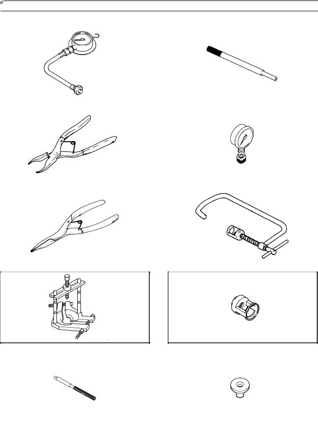
Special Tools and Sealant
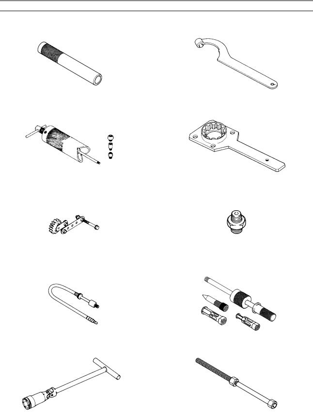
Oil Pressure Gauge, 5 kg/cm2: 57001-125 |
|
Valve Guide Arbor, 7: 57001-163 |
|
|
|
Inside Circlip Pliers: 57001-143 |
|
Compression Gauge: 57001-221 |
|
|
|
|
|
|
Outside Circlip Pliers: 57001-144 |
|
Valve Spring Compressor Assembly: 57001-241 |
|
|
|
|
|
|
Bearing Puller: 57001-158
Valve Spring Compressor Adapter,  28.2: 57001-243
Valve Guide Reamer, 7: 57001-162 |
|
Bearing Puller Adapter: 57001-317 |
|
|
|
1-14 GENERAL INFORMATION
Special Tools and Sealant
Bearing Driver: 57001-382 |
|
Damper Cam Holder: 57001-1025 |
|
|
|
|
|
|
Piston Pin Puller Assembly: 57001-910 |
|
Driven Gear Holder: 57001-1027 |
|
|
|
|
|
|
Gear Holder: 57001-1015 |
|
Oil Pressure Gauge Adapter, PT 1/8: 57001-1033 |
|
|
|
|
|
|
Compression Gauge Adapter, M12 2 1.25: 57001-1018 |
|
Oil Seal & Bearing Remover: 57001-1058 |
|
|
|
|
|
|
Spark Plug Wrench, Hex 18: 57001-1024 |
|
Head Pipe Outer Race Press Shaft: 57001-1075 |
|
|
|
GENERAL INFORMATION 1-15
Special Tools and Sealant
Head Pipe Outer Race Driver: 57001-1077 |
|
Valve Seat Cutter, 45 - 35: 57001-1116 |
|
|
|
|
|
|
Piston Ring Compressor Grip: 57001-1095
Valve Seat Cutter, 32 -  35: 57001-1121
Steering Stem Nut Wrench: 57001-1100
Valve Seat Cutter, 32 –  38.5 : 57001–1122
Head Pipe Outer Race Remover: 57001-1107
Valve Seat Cutter Holder,  7: 57001-1126
Valve Seat Cutter, 45 - 32: 57001-1115 |
|
Valve Seat Cutter Holder Bar: 57001-1128 |
|
|
|
|
|
|
1-16 GENERAL INFORMATION
Special Tools and Sealant
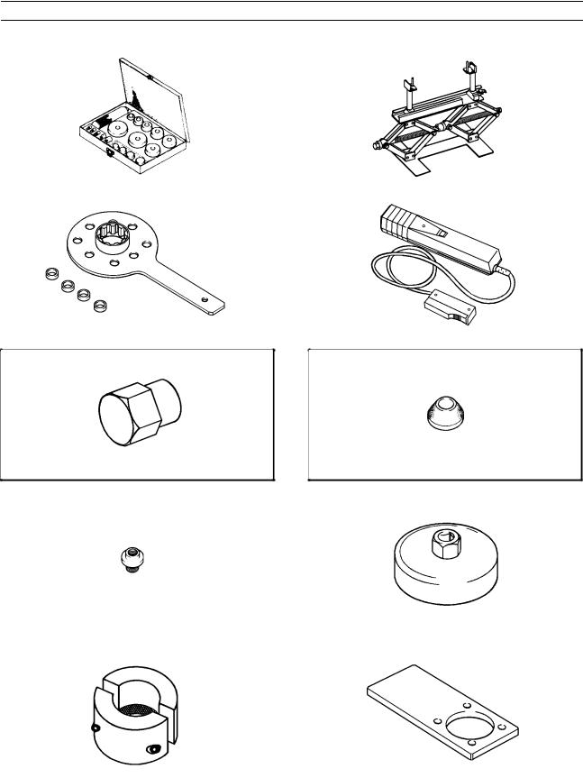
Bearing Driver Set: 57001-1129 |
|
Jack: 57001-1238 |
|
|
|
|
|
|
Pinion Gear Holder: 57001-1165 |
|
Timing Light: 57001-1241 |
|
|
|
|
|
|
Hexagon Wrench, Hex 27: 57001-1210
Valve Seat Cutter, 55 -  35: 57001-1247
Piston Pin Puller Adapter: 57001-1211 |
|
Oil Filter Wrench: 57001-1249 |
|
|
|
|
|
|
Fork Outer Tube Weight: 57001-1218 |
|
Final Gear Case Holder: 57001-1250 |
|
|
|
GENERAL INFORMATION 1-17
Special Tools and Sealant
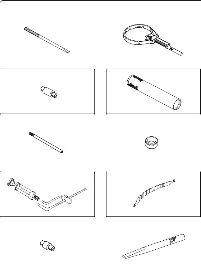
Bearing Remover Shaft, 9: 57001-1265 |
|
Flywheel Holder : 57001–1313 |
|
|
|
|
|
|
Bearing Remover Head,  10 2
10 2  12: 57001-1266
Steering Stem Bearing Driver: 57001-1344
Fork Piston Rod Puller, M12 x 1.25 : 57001–1289 |
|
Steering Stem Bearing Driver Adapter: 57001-1345 |
|
|
|
|
|
|
Fork Oil Level Gauge: 57001-1290
Piston Ring Compressor Belt,  95
95 
 108: 57001-1358
Bearing Remover Head, 20 2 22: 57001-1293 |
|
Bearing Remover Shaft, 13: 57001-1377 |
|
|
|
1-18 GENERAL INFORMATION
Special Tools and Sealant
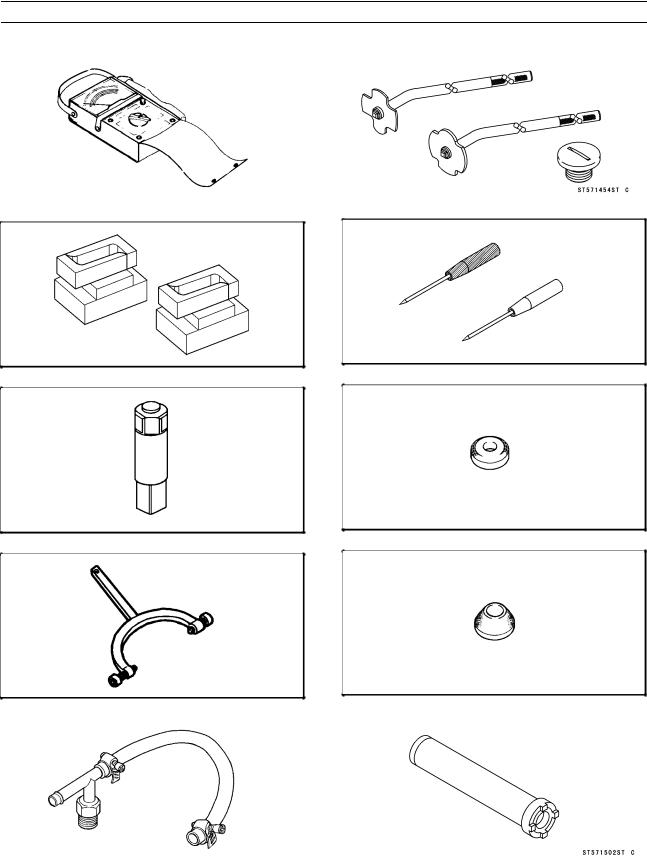
Hand Tester: 57001-1394 |
|
Driver-Filler Cap: 57001–1454 |
|
|
|
|
|
|
|
|
|
Attachment Jack: 57001-1398
Needle Adapter Set: 57001–1457
Drive Shaft Holder: 57001-1407
Valve Seat Cutter, 45 -  40: 57001-1496
Flywheel Holder: 57001-1410
Valve Seat Cutter, 55 -  38.5: 57001-1497
Fuel Pressure Gauge Adapter: 57001-1417 |
|
Fork Cylinder Holder: 57001-1502 |
|
|
|
|
|
|
GENERAL INFORMATION 1-19
Special Tools and Sealant
Kawasaki Bond (Silicone Sealant): 56019–120 |
|
Kawasaki Bond (Liquid Gasket-Black): 92104-1003 |
|
|
|
|
|
|
1-20 GENERAL INFORMATION
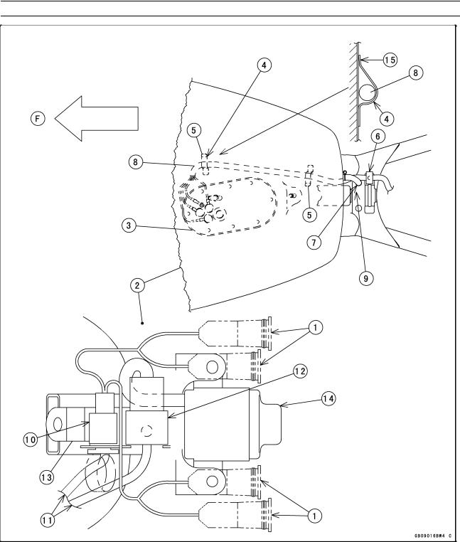
Cable, Wire, and Hose Routing
F: Front
1.Indicator Lights
2.Fuel Tank
3.Fuel Pump Base
4.Two Clamps (fuel pump leads)
5.Plastic Caps
6.Snap-on Plastic Clamps
7.Fuel Tank Breather Hose
8.Fuel Pump Harness
9.Run the harness [8] under the hose [7].
10.Indicator Light Connector : Insert the main harness side connector into the
connector hole of the bracket
[13]and join the connector.
11.Main Harness
12.Ignition Switch Connector : Join the connector and fit them into the hole of the bracket
13.Indicator Unit Bracket
14.Ignition Switch
15.Press each end of clamps by hands against the bottom of the tank. And then, make sure that the ends touch the bottom of the tank.
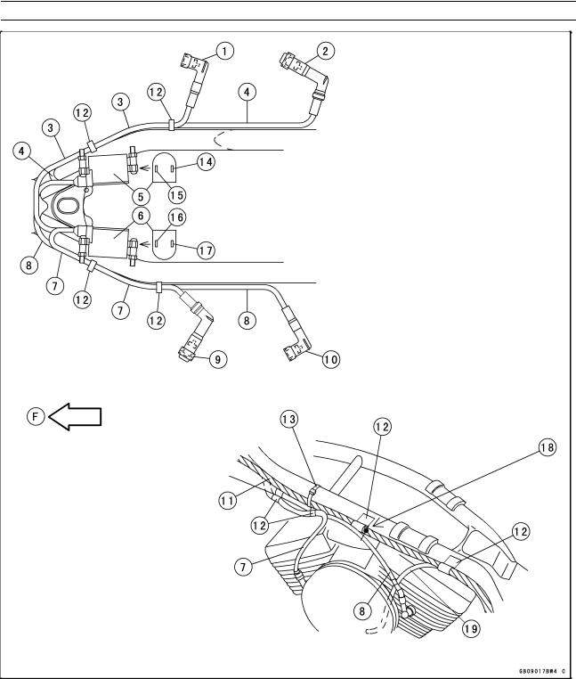
GENERAL INFORMATION 1-21
Cable, Wire, and Hose Routing
F: Front
1.Front Right Spark Plug Cap
2.Rear Right Spark Plug Cap
3.2nd Lead from the left ignition coil lower side
4.2nd Lead from the right ignition coil lower side
5.Ignition Coil for Rear Spark Plugs
6.Ignition Coil for Front Spark Plugs
7.2nd Lead from the left ignition coil upper side
8.2nd Lead from the right ignition coil upper side
9.Front Left Spark Plug Cap
10.Rear Left Spark Plug Cap
11.Clutch Hose
12.Plastic Snap-on Clamps
13.Strap
14.BK/G Primary Lead
15.R/G Primary Lead
16.BK Primary Lead
17.R/G Primary Lead
18.Align the white mark with the back of the clamp [12].
19.Canister Purge Hose (green, CA)
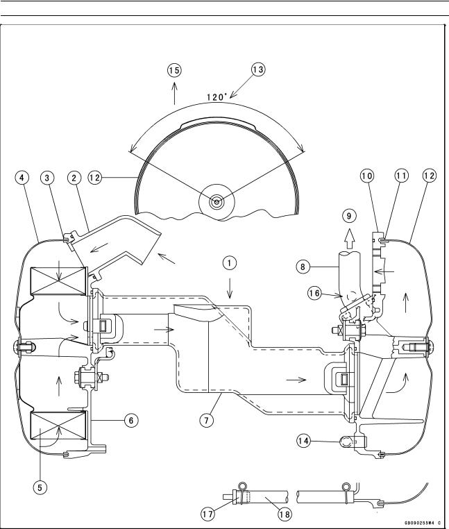
1-22 GENERAL INFORMATION
Cable, Wire, and Hose Routing
!: |
Inlet Air Flow |
10. |
Right Air Cleaner Base |
1. |
Rear View |
11. |
Right Rubber Gasket |
2. |
Air Inlet |
12. |
Right Air Cleaner Cover |
3. |
Left Rubber Gasket |
13. |
Locate the glued joint of the gasket within the angle. |
4. |
Left Air Cleaner Cover |
14. |
Elbow Joint: connected to crankcase breather hose |
5. |
Air Cleaner Element |
15. |
Top |
6. |
Left Air Cleaner Base |
16. |
White Mark on Hose [8] (front side): Position here. |
7. |
Lower Air Cleaner Duct |
17. |
Plug |
8. |
Vacuum Switch Valve Hose |
18. |
Run this drain hose between cylinders. |
9. |
To Vacuum Switch Valve |
|
|

GENERAL INFORMATION 1-23
Cable, Wire, and Hose Routing
!: |
Bypass Air Flow |
9. |
Vacuum Sensor and Pressure |
18. |
ISC Valve #2 (rear cylinder) |
F: |
Front |
|
Regulator |
19. |
ISC Valve Inlets |
1. |
Rear View |
10. |
Strap (holds [4], [6], and [11]) |
20. |
Blue Mark on Top |
2. |
Throttle Assy |
11. |
Vacuum Switch Valve Hose |
21. |
ISC Valve #1 (front cylinder) |
3. |
Air Cleaner Base Seal |
12. |
Right Air Cleaner Base Bolts |
22. |
Inlet Air Temperature Sensor |
4. |
Spark Plug Lead Holder |
13. |
Right Air Cleaner Base |
23. |
Section B-B |
5. |
Right Side View |
14. |
O-rings |
24. |
Crankcase Breather Hose |
6. |
Harness of Inlet Air Tempera- |
15. |
ISC Valve Hose #2 (red) |
25. |
Clamp these leads [6] with a |
|
ture Sensor & ISC Valves |
16. |
ISC Valve Hose #1 (blue) |
|
slack as little as possible. |
7. |
T-Joint |
17. |
Lower Air Cleaner Duct |
26. |
Back of Right Air Cleaner Base |
8.Vacuum Hose from Throttle Body
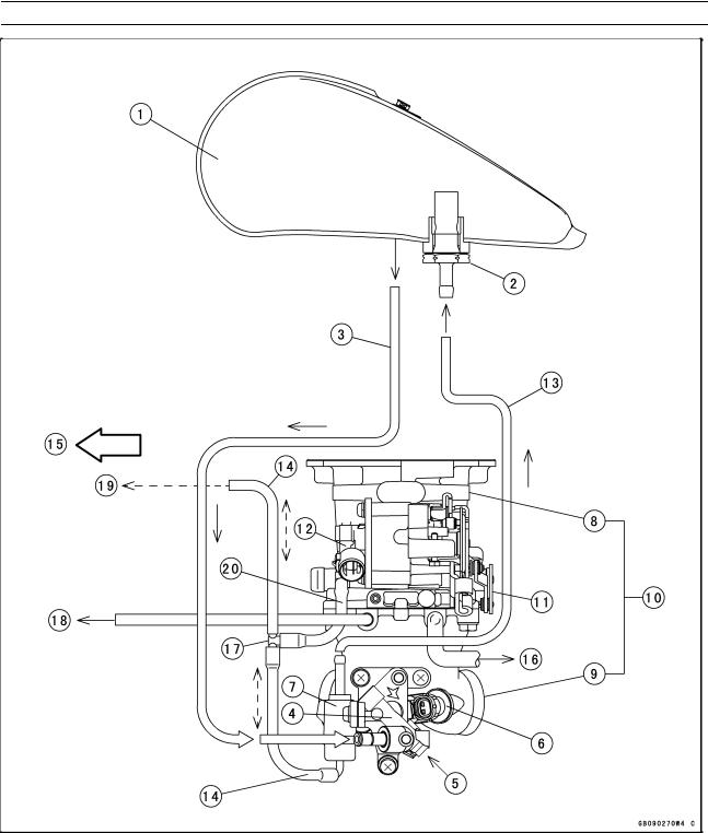
1-24 GENERAL INFORMATION
Cable, Wire, and Hose Routing
- - !: |
Vacuum Pulsation |
5. |
Fuel Injector #1 |
13. |
Low Pressure (Return) Fuel Hose |
!: |
Fuel Flow |
6. |
Fuel Injector #2 |
14. |
Vacuum Hoses from Throttle Body |
#1: |
For Front Cylinder |
7. |
Pressure Regulator |
15. |
Front |
#2: |
For Rear Cylinder |
8. |
Throttle Body |
16. |
Vacuum Hose (white, CA) |
1. |
Fuel Tank (left view) |
9. |
Inlet Manifold |
17. |
T-Joint |
2. |
Return Fuel Check Valve |
10. |
Throttle Assy (top view) |
18. |
Vacuum Switch Valve |
3. |
High Pressure Fuel Hoses |
11. |
Throttle Pulley |
19. |
Vacuum Sensor |
4. |
Delivery Joint |
12. |
Throttle Sensor |
20. |
Throttle Vacuum Hose |
 Loading...