


 Loading...
This manual is brought to you by:
www.magnamaniac.com
Here you can find Service Manuals for over 200 different motorcycles
http://manuals.magnamaniac.com

KX250F
Motorcycle
Service Manual
http://manuals.magnamaniac.com
http://manuals.magnamaniac.com
Quick Reference Guide
This quick reference guide will assist you in locating a desired topic or procedure.
•Bend the pages back to match the black tab of the desired chapter number with the black tab on the edge at each table of contents page.
•Refer to the sectional table of contents for the exact pages to locate the specific topic required.
General Information |
1 |
j |
Periodic Maintenance |
2 |
j |
Fuel System |
3 |
j |
Cooling System |
4 |
j |
Engine Top End |
5 |
j |
Engine Right Side |
6 |
j |
Engine Lubrication System |
7 |
j |
Engine Removal/Installation |
8 |
j |
Crankshaft/Transmission |
9 |
j |
Wheels/Tires |
10 |
j |
Final Drive |
11 |
j |
Brakes |
12 |
j |
Suspension |
13 |
j |
Steering |
14 |
j |
Frame |
15 |
j |
Electrical System |
16 |
j |
Appendix |
17 |
j |
http://manuals.magnamaniac.com
http://manuals.magnamaniac.com

KX250F
Motorcycle
Service Manual
All rights reserved. No parts of this publication may be reproduced, stored in a retrieval system, or transmitted in any form or by any means, electronic mechanical photocopying, recording or otherwise, without the prior written permission of Quality Assurance Department/Consumer Products & Machinery Company/Kawasaki Heavy Industries, Ltd., Japan.
No liability can be accepted for any inaccuracies or omissions in this publication, although every possible care has been taken to make it as complete and accurate as possible.
The right is reserved to make changes at any time without prior notice and without incurring an obligation to make such changes to products manufactured previously. See your Motorcycle dealer for the latest information on product improvements incorporated after this publication.
All information contained in this publication is based on the latest product information available at the time of publication. Illustrations and photographs in this publication are intended for reference use only and may not depict actual model component parts.
http://manuals.magnamaniac.com
© 2003 Kawasaki Heavy Industries, Ltd. |
Second Edition (1) : Jan. 16 2004 (K) |
LIST OF ABBREVIATIONS
|
|
|
|
|
A |
ampere(s) |
lb |
pound(s) |
|
ABDC |
after bottom dead center |
m |
meter(s) |
|
AC |
alternating current |
min |
minute(s) |
|
ATDC |
after top dead center |
N |
newton(s) |
|
BBDC |
before bottom dead center |
Pa |
pascal(s) |
|
BDC |
bottom dead center |
PS |
horsepower |
|
BTDC |
before top dead center |
psi |
pound(s) per square inch |
|
°C |
degree(s) Celsius |
r |
revolution |
|
DC |
direct current |
r/min, rpm |
revolution(s) per minute |
|
F |
farad(s) |
TDC |
top dead center |
|
°F |
degree(s) Fahrenheit |
TIR |
total indicator reading |
|
ft |
foot, feet |
V |
volt(s) |
|
g |
gram(s) (mass) |
W |
watt(s) |
|
h |
hour(s) |
Ω |
ohm(s) |
|
kg |
(mass) |
|
|
|
kgf |
(force) |
|
|
|
L |
liter(s) |
|
|
|
http://manuals.magnamaniac.com
Foreword
This manual is designed primarily for use by trained mechanics in a properly equipped shop. However, it contains enough detail and basic information to make it useful to the owner who desires to perform his own basic maintenance and repair work. A basic knowledge of mechanics, the proper use of tools, and workshop procedures must be understood in order to carry out maintenance and repair satisfactorily. Whenever the owner has insufficient experience or doubts his ability to do the work, all adjustments, maintenance, and repair should be carried out only by qualified mechanics.
In order to perform the work efficiently and to avoid costly mistakes, read the text, thoroughly familiarize yourself with the procedures before starting work, and then do the work carefully in a clean area. Whenever special tools or equipment are specified, do not use makeshift tools or equipment. Precision measurements can only be made if the proper instruments are used, and the use of substitute tools may adversely affect safe operation.
•To get the longest life out of your vehicle: Follow the Periodic Maintenance Chart in the
•Service Manual.
Be alert for problems and non-scheduled
•maintenance.
Use proper tools and genuine Kawasaki Motorcycle parts. Special tools, gauges, and testers that are necessary when servicing Kawasaki motorcycles are introduced by the Special Tool Catalog or Manual. Genuine parts provided as spare parts are listed in the
•Parts Catalog.
Follow the procedures in this manual care-
•fully. Don’t take shortcuts.
Remember to keep complete records of maintenance and repair with dates and any new parts installed.
How to Use This Manual
In preparing this manual, we divided the product into its major systems. These systems became the manual’s chapters. All information for a particular system from adjustment through disassembly and inspection is located in a single chapter.
The Quick Reference Guide shows you all of the product’s system and assists in locating their chapters. Each chapter in turn has its own comprehensive Table of Contents.
The Periodic Maintenance Chart is located in the Periodic Maintenance chapter. The chart gives a time schedule for required maintenance operations.
If you want spark plug information, for example, go to the Periodic Maintenance Chart first. The chart tells you how frequently to clean and gap the plug. Next, use the Quick Reference Guide to locate the Periodic Maintenance chapter. Then, use the Table of Contents on the first page of the chapter to find the Spark Plug section.
Whenever you see these WARNING and CAUTION symbols, heed their instructions! Always follow safe operating and maintenance practices.


 WARNING
This warning symbol identifies special instructions or procedures which, if not correctly followed, could result in personal injury, or loss of life.
CAUTION
This caution symbol identifies special instructions or procedures which, if not strictly observed, could result in damage to or destruction of equipment.
This manual contains four more symbols (in addition to WARNING and CAUTION) which will help you distinguish different types of information.
http://manuals.magnamaniac.com

NOTE
○This note symbol indicates points of particular interest for more efficient and convenient operation.
•Indicatesdone. a procedural step or work to be ○Indicates a procedural sub-step or how to do the work of the procedural step it follows. It
also precedes the text of a NOTE.
Indicates a conditional step or what action to take based on the results of the test or inspection in the procedural step or sub-step it follows.
In most chapters an exploded view illustration of the system components follows the Table of Contents. In these illustrations you will find the instructions indicating which parts require specified tightening torque, oil, grease or a locking agent during assembly.
http://manuals.magnamaniac.com

GENERAL INFORMATION 1-1
General Information |
1 |
Table of Contents |
|
Before Servicing ..................................................................................................................... |
1-2 |
Model Identification................................................................................................................. |
1-7 |
General Specifications............................................................................................................ |
1-8 |
Unit Conversion Table ............................................................................................................ |
1-10 |
http://manuals.magnamaniac.com
1-2 GENERAL INFORMATION
Before Servicing
Before starting to perform an inspection service or carry out a disassembly and reassembly operation on a motorcycle, read the precautions given below. To facilitate actual operations, notes, illustrations, photographs, cautions, and detailed descriptions have been included in each chapter wherever necessary. This section explains the items that require particular attention during the removal and reinstallation or disassembly and reassembly of general parts.
Especially note the following:
Edges of Parts
Lift large or heavy parts wearing gloves to prevent injury from possible sharp edges on the parts.
Solvent
Use a high flush point solvent when cleaning parts. High flush point solvent should be used according to directions of the solvent manufacturer.
Cleaning vehicle before disassembly
Clean the vehicle thoroughly before disassembly. Dirt or other foreign materials entering into sealed areas during vehicle disassembly can cause excessive wear and decrease performance of the vehicle.
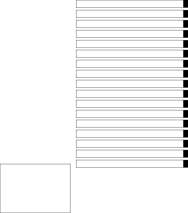
Arrangement and Cleaning of Removed Parts
Disassembled parts are easy to confuse. Arrange the parts according to the order the parts were disassembled and clean the parts in order prior to assembly.
http://manuals.magnamaniac.com
GENERAL INFORMATION 1-3
Before Servicing
Storage of Removed Parts
After all the parts including subassembly parts have been cleaned, store the parts in a clean area. Put a clean cloth or plastic sheet over the parts to protect from any foreign materials that may collect before re-assembly.
Inspection
Reuse of worn or damaged parts may lead to serious accident. Visually inspect removed parts for corrosion, discoloration, or other damage. Refer to the appropriate sections of this manual for service limits on individual parts. Replace the parts if any damage has been found or if the part is beyond its service limit.
Replacement Parts
Replacement Parts must be KAWASAKI genuine or recommended by KAWASAKI. Gaskets, O rings, Oil seals, Grease seals, circlips or cotter pins must be replaced with new ones whenever disassembled.
Assembly Order
In most cases assembly order is the reverse of disassembly, however, if assembly order is provided in this Service Manual, follow the procedures given.
Tightening Sequence
Bolts, nuts, or screws must be tightened according to the specified sequence to prevent case warpage or deformation which can lead to malfunction. If the specified tightening sequence is not indicated, tighten the fasteners alternating diagonally.
http://manuals.magnamaniac.com
1-4 GENERAL INFORMATION
Before Servicing
Tightening Torque
Incorrect torque applied to a bolt, nut, or screw may lead to serious damage. Tighten fasteners to the specified torque using a good quality torque wrench.
Often, the tightening sequence is followed twice-initial tightening and final tightening with torque wrench.
Force
Use common sense during disassembly and assembly, excessive force can cause expensive or hard to repair damage. When necessary, remove screws that have a non -permanent locking agent applied using an impact driver. Use a plastic-faced mallet whenever tapping is necessary.
Gasket, Oring
Hardening, shrinkage, or damage of both gaskets and O-rings after disassembly can reduce sealing performance. Remove old gaskets and clean the sealing surfaces thoroughly so that no gasket material or other material remains. Install new gaskets and replace used O-rings when re-assembling
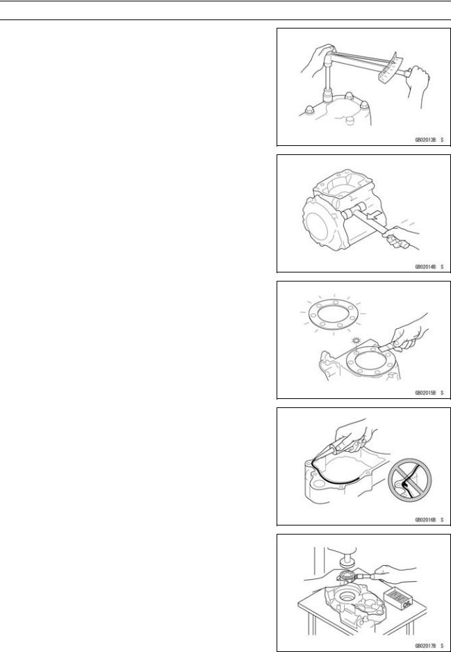
Liquid Gasket, Locking Agent
For applications that require Liquid Gasket or a Locking agent, clean the surfaces so that no oil residue remains before applying liquid gasket or locking agent. Do not apply them excessively. Excessive application can clog oil passages and cause serious damage.
Press
For items such as bearings or oil seals that must be pressed into place, apply small amount of oil to the contact area. Be sure to maintain proper alignment and use smooth movements when installing.
http://manuals.magnamaniac.com
GENERAL INFORMATION 1-5
Before Servicing
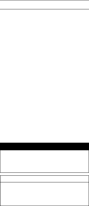
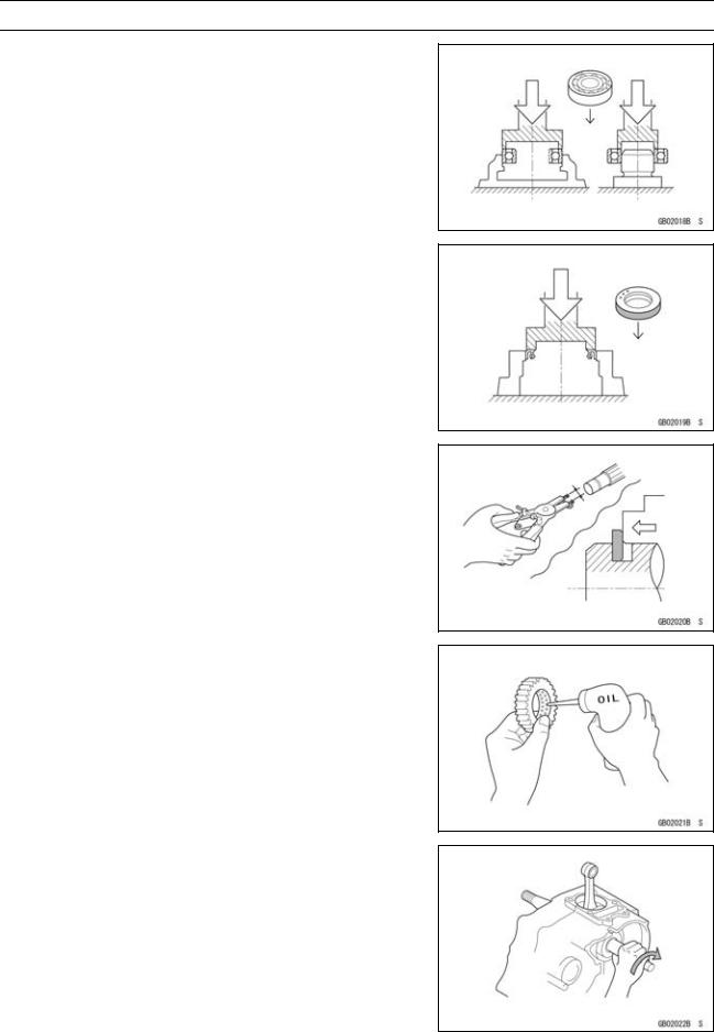
Ball Bearing and Needle Bearing
Do not remove pressed ball or needle unless removal is absolutely necessary. Replace with new ones whenever removed. Press bearings with the manufacturer and size marks facing out. Press the bearing into place by putting pressure on the correct bearing race as shown.
Pressing the incorrect race can cause pressure between the inner and outer race and result in bearing damage.
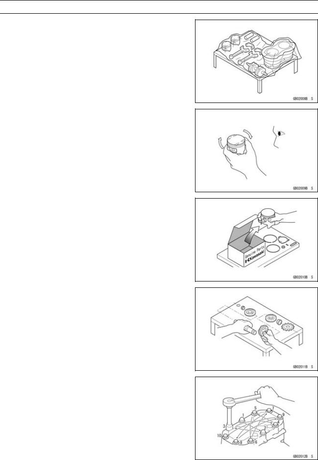
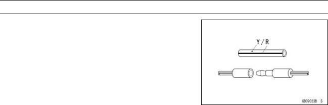
Oil Seal, Grease Seal
Do not remove pressed oil or grease seals unless removal is necessary. Replace with new ones whenever removed. Press new oil seals with manufacture and size marks facing out. Make sure the seal is aligned properly when installing.
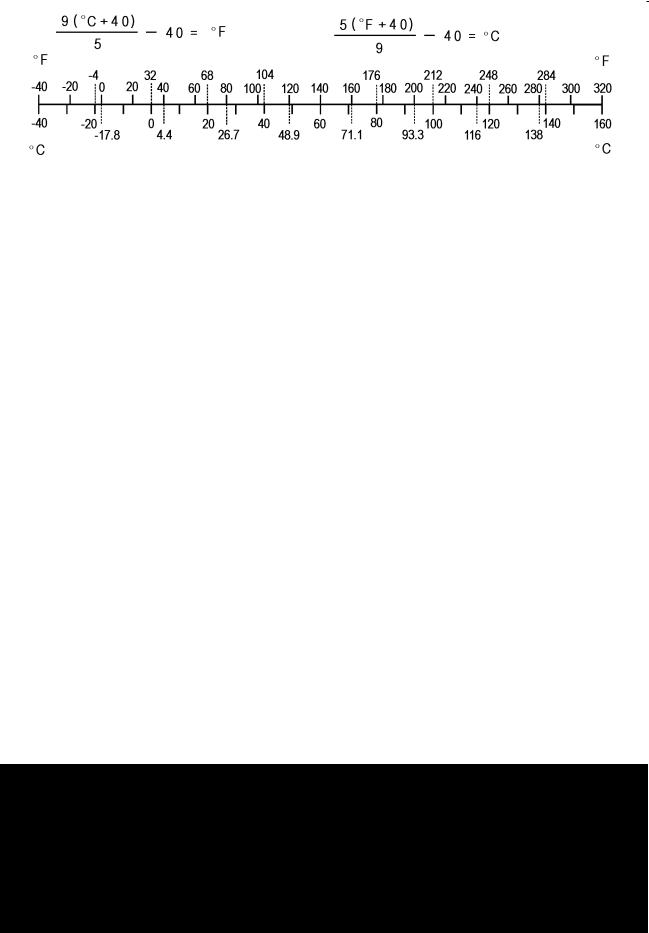
Circlips, Cotter Pins
Replace circlips or cotter pins that were removed with new ones. Install the circlip with its sharp edge facing outward and its chamfered side facing inward to prevent the clip from being pushed out of its groove when loaded. Take care not to open the clip excessively when installing to prevent deformation.
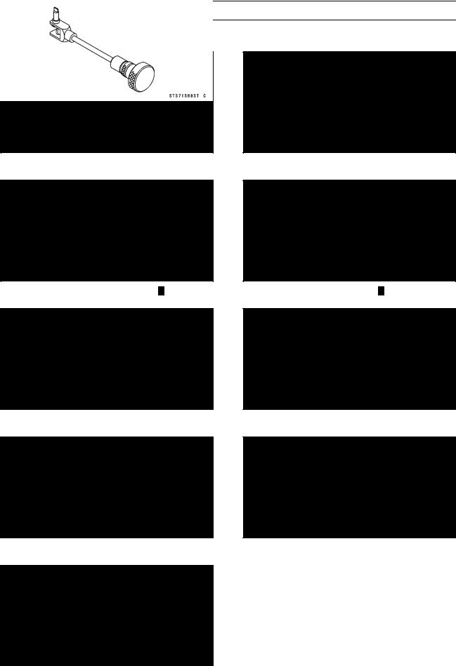
Lubrication
It is important to lubricate rotating or sliding parts during assembly to minimize wear during initial operation. Lubrication points are called out throughout this manual, apply the specific oil or grease as specified.
Direction of Engine Rotation
When rotating the crankshaft by hand, the free play amount of rotating direction will affect the adjustment. Rotate the crankshaft to positive direction (clockwise viewed from output side).
http://manuals.magnamaniac.com
1-6 GENERAL INFORMATION
Before Servicing
Electrical Wires
A two-color wire is identified first by the primary color and then the stripe color. Unless instructed otherwise, electrical wires must be connected to those of the same color.
http://manuals.magnamaniac.com
 User Manual")
GENERAL INFORMATION 1-7
Model Identification
KX250–N1 Left Side View
KX250–N1 Right Side View
http://manuals.magnamaniac.com

1-8 GENERAL INFORMATION
General Specifications
|
|
|
|
|
Items |
|
|
KX250–N1 |
|
Dimensions: |
|
|
|
|
Overall length |
|
|
2 170 mm (85.43 in.) |
|
Overall width |
|
|
840 mm (33.1 in.) |
|
Overall height |
|
|
1 270 mm (50 in.) |
|
Wheelbase |
|
|
1 475 mm (8.07 in.) |
|
Road clearance |
|
|
340 mm (13.4 in.) |
|
Seat height |
|
|
960 mm (37.8 in.) |
|
Dry mass |
|
|
92.5 kg (204 lb) |
|
Curb mass: |
Front |
49.9 kg (110 lb) |
||
|
Rear |
52.6 kg (116 lb) |
||
Fuel tank capacity |
|
|
7.5 L (2.0 US gal) |
|
Performance |
|
|
|
|
Minimum turning radius |
|
|
— |
|
Engine: |
|
|
|
|
Type |
|
|
4-stroke, single cylinder, DOHC 4 valve |
|
Cooling system |
|
|
Liquid-cooled |
|
Bore and stroke |
|
|
77.0 × 53.6 mm (3.03 × 2.11 in.) |
|
Displacement |
|
|
249 mL (15.2 cu in.) |
|
Compression ratio |
|
|
12.6 : 1 |
|
Maximum horsepower |
|
|
31.6 kW (43.0 PS) @11 000 r/min (rpm) |
|
Maximum torque |
|
|
28.7 N·m (2.93 kgf·m, 6.45 in·lb) @ 8 500 r/min (rpm) |
|
Carburetion system |
|
|
Carburetor, KEIHIN FCR37 |
|
Starting system |
|
|
Primary kick |
|
Ignition system |
|
|
Digital AC-CDI |
|
Timing advance |
|
|
|
|
Ignition timing |
|
|
BTDC 8° @ 2 000 r/min (rpm) |
|
Spark plug |
|
|
NGK CR8EB or NGK CR9EB |
|
Valve timing |
|
|
|
|
Inlet |
Open |
BTDC 49° |
||
|
Close |
ABDC 63° |
||
|
Duration |
292° |
|
|
Exhaust |
Open |
BBDC 69° |
||
|
Close |
ATDC 49° |
||
|
Duration |
298° |
|
|
Lubrication system |
|
|
Forced lubrication (semi-dry sump) |
|
Engine oil: |
|
|
|
|
Type |
|
|
API SH or SJ with JASO MA |
|
Viscosity |
|
|
SAE 10W-40 |
|
Capacity |
|
|
1.5 L (1.6 USqt) |
|
Drive Train: |
|
|
|
|
Primary reduction system: |
Gear |
|||
Type |
|
http://manuals |
||
|
|
.magnamaniac.com |
||
Reduction ratio |
|
|
3.350 (67/20) |
|
Clutch type |
|
|
Wet, multi disc |
|

General Specifications
|
|
|
Items |
|
KX250–N1 |
Transmission: |
|
|
Type |
|
5-speed, constant mesh, return shift |
Gear ratios: |
1st |
2.142 (30/14) |
|
2nd |
1.785 (25/14) |
|
3rd |
1.444 (26/18) |
|
4th |
1.200 (24/20) |
Final drive system: |
5th |
1.052 (20/19) |
|
|
|
Type |
|
Chain drive |
Reduction ratio |
|
3.692 (48/13) |
Overall drive ratio |
|
13.020 @ Top gear |
Frame: |
|
|
Type |
|
Tubular, semi-double cradle |
Steering angle |
|
42° to either side |
Caster (rake angle) |
|
26.5° |
Trail |
|
110 mm (4.33 in.) |
Front tire: |
Size |
80/100-21 51M |
|
Make/Type |
BRIDGESTONE M601 (EU, M201) Tube type |
Rear tire: |
Size |
100/90-19 57M |
|
Make/Type |
BRIDGESTONE M602 (EU, M202) Tube type |
Front suspension: |
Type |
Telescopic fork (up side down) |
|
Wheel travel |
300 mm (11.8 in.) |
Rear suspension: |
Type |
Swingarm (New Uni-trak) |
|
Wheel travel |
310 mm (12.2 in.) |
Brake type: |
Front and Rear |
Single disc |
Effective disc diameter: |
|
|
Front (effect. dia.) |
225 mm (8.86 in.) |
|
|
Rear (effect. dia.) |
215 mm (8.46 in.) |
EU: European Model |
|
|
Specifications are subject to change without notice, and may not apply to every country. |
||
http://manuals.magnamaniac.com
1-10 GENERAL INFORMATION
Unit Conversion Table
|
Prefixes for Units: |
|
|
|
|
Units of Length: |
|
|
||||
|
|
|
|
|
|
|
|
km |
× |
0.6214 |
= |
mile |
|
Prefix |
|
Symbol |
|
Power |
|||||||
|
|
|
|
|
m |
× |
3.281 |
= |
ft |
|||
|
mega |
|
M |
× 1 000 000 |
|
|
||||||
|
|
|
|
mm |
× |
0.03937 |
= |
in |
||||
|
kilo |
|
k |
× |
1 000 |
|
|
|||||
|
|
|
|
|
|
|
|
|
||||
|
centi |
|
c |
× |
0.01 |
|
|
|
|
|
|
|
|
milli |
|
m |
× |
0.001 |
|
|
Units of Torque: |
|
|
||
|
micro |
|
µ |
× 0.000001 |
|
|
|
|
||||
|
|
|
|
|
|
|
|
N·m |
× |
0.1020 |
= |
kgf·m |
|
|
|
|
|
|
|
|
N·m |
× |
0.7376 |
= |
ft·lb |
|
Units of Mass: |
|
|
|
|
N·m |
× |
8.851 |
= |
in·lb |
||
|
|
|
|
|
kgf·m |
× |
9.807 |
= |
N·m |
|||
|
kg |
× |
2.205 |
= |
lb |
|
|
|||||
|
|
|
kgf·m |
× |
7.233 |
= |
ft·lb |
|||||
|
g |
× |
0.03527 |
= |
oz |
|
|
|||||
|
|
|
kgf·m |
× |
86.80 |
= |
in·lb |
|||||
|
|
|
|
|
|
|
|
|||||
|
Units of Volume: |
|
|
|
|
Units of Pressure: |
|
|
||||
|
L |
× |
0.2642 |
= |
gal (US) |
|
|
|
|
|||
|
|
|
kPa |
× |
0.01020 |
= |
kgf/cm² |
|||||
|
L |
× |
0.2200 |
= |
gal (imp) |
|
|
|||||
|
|
|
kPa |
× |
0.1450 |
= |
psi |
|||||
|
L |
× |
1.057 |
= |
qt (US) |
|
|
|||||
|
|
|
kPa |
× |
0.7501 |
= |
cm Hg |
|||||
|
L |
× |
0.8799 |
= |
qt (imp) |
|
|
|||||
|
|
|
kgf/cm² |
× |
98.07 |
= |
kPa |
|||||
|
L |
× |
2.113 |
= |
pint (US) |
|
|
|||||
|
|
|
kgf/cm² |
× |
14.22 |
= |
psi |
|||||
|
L |
× |
1.816 |
= |
pint (imp) |
|
|
|||||
|
|
|
cm Hg |
× |
1.333 |
= |
kPa |
|||||
|
mL |
× |
0.03381 |
= |
oz (US) |
|
|
|||||
|
|
|
|
|
|
|
|
|||||
|
mL |
× |
0.02816 |
= |
oz (imp) |
|
|
|
|
|
|
|
|
mL |
× |
0.06102 |
= |
cu in |
|
|
Units of Speed: |
|
|
||
|
|
|
|
|
|
|
|
|
|
|||
|
|
|
|
|
|
|
|
km/h |
× |
0.6214 |
= |
mph |
|
Units of Force: |
|
|
|
|
|
|
|
|
|
||
|
N |
× |
0.1020 |
= |
kgf |
|
|
Units of Power: |
|
|
||
|
N |
× |
0.2248 |
= |
lb |
|
|
|
|
|||
|
kgf |
× |
9.807 |
= |
N |
|
|
kW |
× |
1.360 |
= |
PS |
|
kgf |
× |
2.205 |
= |
lb |
|
|
kW |
× |
1.341 |
= |
HP |
|
|
|
|
|
|
|
|
PS |
× |
0.7355 |
= |
kW |
|
|
|
|
|
|
|
|
PS |
× |
0.9863 |
= |
HP |
Units of Temperature:
http://manuals.magnamaniac.com

PERIODIC MAINTENANCE 2-1
Periodic Maintenance
|
|
|
Table of Contents |
2 |
|
|
|
Periodic Maintenance Chart .............. |
2-2 |
Tires Inspection............................ |
2-29 |
||
Torque and Locking Agent................. |
2-4 |
Spoke Tightness Inspection......... |
2-29 |
||
Specifications .................................... |
|
2-8 |
Rim Runout Inspection................. |
2-30 |
|
Special Tools ..................................... |
|
2-10 |
Wheel Bearing Inspection ............ |
2-30 |
|
Periodic Maintenance Procedures..... |
2-11 |
Final Drive....................................... |
2-31 |
||
Fuel System.................................... |
|
2-11 |
Drive Chain Wear Inspection ....... |
2-31 |
|
Fuel Hose and Connection |
|
Drive Chain Lubrication................ |
2-31 |
||
Inspection.................................. |
|
2-11 |
Sprocket Wear Inspection............ |
2-32 |
|
Throttle Grip Free Play Inspection |
2-11 |
Rear Sprocket Warp Inspection ... |
2-32 |
||
Throttle Grip Free Play |
|
Brakes............................................. |
2-33 |
||
Adjustment ................................ |
|
2-11 |
Brake Lever and Pedal |
|
|
Hot Start Lever Free Play |
|
Adjustment ................................ |
2-33 |
||
Inspection.................................. |
|
2-12 |
Brake Fluid Level Inspection........ |
2-34 |
|
Idle Speed Inspection .................. |
2-12 |
Brake Fluid Change ..................... |
2-35 |
||
Idle Speed Adjustment................. |
2-13 |
Brake Pad Wear Inspection ......... |
2-37 |
||
Air Cleaner Element Cleaning and |
|
Brake Master Cylinder Cup and |
|
||
Inspection.................................. |
|
2-13 |
Dust Seal Replacement ............ |
2-38 |
|
Cooling System............................... |
|
2-15 |
Caliper Piston Seal and Dust Seal |
|
|
Coolant Level Inspection.............. |
2-15 |
Replacement............................. |
2-39 |
||
Coolant Deterioration Inspection.. |
2-16 |
Brake Hose and Connection |
|
||
Radiator Hoses and Connections |
|
Check ........................................ |
2-42 |
||
Inspection.................................. |
|
2-16 |
Brake Hose Replacement............ |
2-42 |
|
Engine Top End .............................. |
|
2-17 |
Suspension..................................... |
2-44 |
|
Valve Clearance Inspection ......... |
2-17 |
Front Fork Inspection ................... |
2-44 |
||
Valve Clearance Adjustment........ |
2-17 |
Front Fork Oil Change (each fork |
|
||
Cylinder Head Warp Inspection ... |
2-19 |
leg) ............................................ |
2-44 |
||
Cylinder Wear Inspection............. |
2-20 |
Rear Shock Absorber Oil Change |
2-46 |
||
Piston/Cylinder Clearance ........... |
2-20 |
Swingarm and Uni-Trak Linkage |
|
||
Piston, Piston Ring and Piston |
|
Inspection.................................. |
2-51 |
||
Pin Replacement....................... |
|
2-20 |
Swingarm and Uni-Track Linkage |
|
|
Exhaust System ........................... |
|
2-21 |
Pivot Lubricate .......................... |
2-51 |
|
Silencer Packing Change............. |
2-21 |
Steering .......................................... |
2-52 |
||
Engine Right Side........................... |
|
2-22 |
Steering Inspection ...................... |
2-52 |
|
Clutch Adjustment........................ |
|
2-22 |
Steering Adjustment .................... |
2-52 |
|
Friction and Steel Plates |
|
Stem Bearing Lubrication............. |
2-54 |
||
Inspection.................................. |
|
2-23 |
Frame ............................................. |
2-54 |
|
Engine Lubrication System ............. |
2-23 |
Frame Inspection ......................... |
2-54 |
||
Engine Oil Change....................... |
|
2-23 |
Electrical System ............................ |
2-54 |
|
Oil Filter Change .......................... |
|
2-24 |
Spark Plug Cleaning and |
|
|
Oil Screen Cleaning ..................... |
|
2-26 |
Inspection.................................. |
2-54 |
|
Breather Hose Inspection ............ |
2-26 |
Cable Inspection............................. |
2-55 |
||
Crankshaft/Transmission ................ |
2-26 |
Lubrication ................................... |
2-55 |
||
Crankshaft Inspection .................. |
2-26 |
Nut, Bolt, and Fastener Tightness |
|
||
Wheel/Tires |
http://manuals.magnamaniac.com |
2-57 |
|||
|
2-28 |
Inspection |
..................................... |
||
Air Pressure |
|
|
Tightness Inspection .................... |
2-57 |
|
Inspection/Adjustment............... |
2-28 |
|
|
|
|
2-2 PERIODIC MAINTENANCE
Periodic Maintenance Chart
The maintenance must be done in accordance with this chart to keep the motorcycle in good running condition.
|
|
|
|
|
|
|
|
|
|
|
FREQUENCY |
Each |
Every 3 |
Every 6 |
Every 12 |
See |
|
OPERATION |
|
race |
races |
races |
races |
Page |
||
|
|
|
• |
|
|
|
|
|
|
Spark plug – clean, gap † |
• |
|
|
|
|
2-54 |
|
|
|
|
|
|
|
|
|
|
|
Clutch – adjust |
|
|
• |
|
|
2-22 |
|
|
|
|
|
|
|
|
||
|
Clutch and friction plates - inspect † |
• |
|
|
R |
|
2-23 |
|
|
|
|
|
|
|
|
|
|
|
Throttle cable – adjust |
|
• |
|
|
|
|
2-11 |
|
|
|
|
|
|
|
|
|
|
Air cleaner element – clean |
|
|
|
|
|
2-13 |
|
|
Air cleaner element – replace |
• |
If damaged |
|
2-13 |
|||
|
|
|
|
|
|
|
|
|
|
Carburetor – inspect and adjust |
|
|
|
• |
|
2-12 |
|
|
|
|
|
|
|
|
|
|
|
Engine Oil – change |
|
|
|
|
• |
|
2-23 |
|
|
|
|
|
|
|
|
|
E |
Piston and piston ring – replace |
|
|
|
|
|
2-20 |
|
|
|
|
|
|
|
|
|
|
Cylinder head, cylinder – inspect |
|
|
|
• |
|
2-20 |
||
N |
|
|
|
|
||||
G |
Piston pin – replace |
|
|
|
|
|
• |
2-20 |
I |
Valve clearance – inspect † |
|
|
|
• |
|
2-17 |
|
N |
|
|
|
|
||||
E |
Hot start – adjust |
|
• |
|
|
• |
|
2-12 |
|
|
|
|
|
|
|
|
|
|
Oil filter – replace |
|
• |
|
|
|
|
2-24 |
|
|
|
|
|
|
|
|
|
|
Silencer – clean and inspect† |
|
|
|
• |
|
2-21 |
|
|
|
|
|
|
|
|
|
|
|
Silencer packing – change |
• |
|
|
|
|
2-21 |
|
|
|
|
|
|
|
|
|
|
|
Kick pedal and shift pedal – clean |
• |
|
|
|
|
— |
|
|
|
|
|
|
|
|
|
|
|
Engine sprocket – inspect † |
• |
|
|
|
|
2-32 |
|
|
|
|
|
|
|
|
|
|
|
Coolant – check † |
|
• |
|
|
|
|
2-15 |
|
|
|
|
|
|
|
|
|
|
Radiator hoses and connections – inspect † |
|
|
|
• |
|
2-16 |
|
|
|
|
|
|
|
|
|
|
|
Crankshaft – inspect |
|
|
|
|
• |
|
2-26 |
|
|
|
|
|
|
|
|
|
|
Oil screen – clean |
|
• |
|
|
|
|
2-26 |
|
|
|
|
|
|
|
|
|
|
Breather hose – inspect |
|
• |
|
|
|
|
2-26 |
|
|
|
|
|
|
|
|
|
|
Brake adjustment – inspect † |
• |
|
|
|
|
2-33 |
|
|
|
|
|
|
|
|
|
|
|
Brake pad wear – inspect † |
• |
|
|
|
|
2-37 |
|
|
|
|
|
|
|
|
|
|
|
Brake fluid level – inspect † |
|
|
|
|
|
2-34 |
|
C |
Brake fluid – change |
|
|
Every 2 years |
|
2-35 |
||
Brake master cylinder cup and dust seal – replace |
|
Every 2 years |
|
2-38 |
||||
H |
|
|
|
|
|
|
|
|
Brake caliper piston seal and dust seal – replace |
|
Every 2 years |
|
2-39 |
||||
A |
|
|
||||||
S |
Brake hoses and pipe – replace |
• |
Every 4 years |
|
2-42 |
|||
S |
Brake hoses, connections - inspect † |
|
|
|
|
|
2-42 |
|
I |
|
|
|
|
|
|
|
|
Spoke tightness and rim runout – inspect † |
• |
|
|
|
|
2-29 |
||
S |
|
|
|
|
||||
|
|
|
• |
|
|
|
|
|
|
Wheel bearing – inspect † |
• |
|
|
|
|
2-30 |
|
|
|
|
|
|
|
|
|
|
|
Frame – inspect |
|
|
|
|
|
|
2-54 |
|
|
|
|
|
|
|
|
|
|
Drive chain wear – inspect † |
• |
|
|
|
|
2-31 |
|
|
|
|
• |
.com |
|
|
|
|
|
Wheels/tires – inspect |
http://manuals.magnamaniac |
|
|
2-28 |
|||
|
|
• |
|
|
|
|
||
|
|
|
|
|
|
|
|
|
|
Rear sprocket – inspect † |
|
|
|
|
|
2-32 |
|
|
|
|
|
|
|
|
|
|

PERIODIC MAINTENANCE 2-3
Periodic Maintenance Chart
|
|
|
|
|
|
|
|
|
FREQUENCY |
|
Each |
Every 3 |
Every 6 |
Every 12 |
See |
OPERATION |
|
race |
races |
races |
races |
Page |
|
|
|
|
• |
|
|
|
|
|
Front fork – inspect and clean |
|
|
|
• |
|
2-44 |
|
|
|
|
|
|
|
|
|
Front fork oil – change |
|
|
|
• |
|
2-44 |
|
|
|
|
|
|
|
|
|
Rear shock oil – replace |
|
• |
|
|
|
2-46 |
|
|
|
|
|
|
|
|
|
Cable – inspect |
|
|
|
|
|
2-55 |
|
|
|
|
|
|
|
|
|
Fuel hose – replace |
|
• |
Every 4 years |
|
2-11 |
|
|
|
|
|
|
|
|
|
|
Fuel hose, connections - inspect † |
|
• |
|
|
|
2-11 |
|
|
|
|
|
|
|
|
|
Steering play – inspect † |
|
|
|
• |
|
2-52 |
|
|
|
|
|
|
|
|
|
Steering stem bearing – grease |
|
|
• |
|
|
2-54 |
|
|
|
|
|
|
|
|
|
Swingarm and Uni-Trak linkage pivots – grease |
|
|
• |
|
|
2-51 |
|
|
|
|
|
|
|
|
|
Swingarm and Uni-Trak linkage pivots – inspect † |
|
|
|
|
|
2-51 |
|
|
|
|
|
|
|
|
|
Nuts, bolts, fasteners – inspect † |
|
• |
|
|
|
2-57 |
|
|
|
|
|
|
|
|
†: Replace, add, adjust, clean or torque if necessary. |
|
|
|
|
|
||
R: Replace |
|
|
|
|
|
||
http://manuals.magnamaniac.com

2-4 PERIODIC MAINTENANCE
Torque and Locking Agent
Tighten all bolts and nuts to the proper torque using an accurate torque wrench. If insufficiently |
||||||
tightened, a bolt or nut may become damaged, strip an internal thread, or break and then fall out. The |
||||||
following table lists the tightening toque for the major bolts and nuts, and the parts requiring use of a |
||||||
non-permanent locking agent or liquid gasket. |
|
|
|
|
|
|
When checking the tightening toque of the bolts and nuts, first loosen the bolt or nut by half a turn |
||||||
and then tighten to specified torque. |
|
|
|
|
|
|
Letters used in the "Remarks" column mean: |
|
|
|
|
|
|
AL: Tighten the two clamp bolts alternately two times to ensure even tightening torque. |
|
|||||
L: Apply a non-permanent locking agent to the threads. |
|
|
|
|
||
Lh: Left-hand Threads |
|
|
|
|
|
|
S: Tighten the fasteners following the specified sequence. |
|
|
|
|
||
|
|
|
|
|
|
|
Fastener |
|
|
Torque |
|
|
Remarks |
|
N·m |
kgf·m |
ft·lb |
|||
|
|
|
||||
Fuel System: |
|
|
|
|
|
|
Throttle Pulley Cover Bolt |
|
3.4 |
0.3 |
30 |
in·lb |
|
Throttle Cable Locknut |
|
7.0 |
0.7 |
61 |
in·lb |
|
Plunger Cap Bolt |
|
1.0 |
0.1 |
10 |
in·lb |
|
Rear Frame Mounting Bolts |
|
34 |
3.5 |
|
25 |
|
Air Cleaner Duct Clamp Screw |
|
2.0 |
0.2 |
17 |
in·lb |
|
Fuel Tap Plate Mounting Screws |
|
0.8 |
0.08 |
7 in·lb |
|
|
Cooling System: |
|
|
|
|
|
|
Right Engine Cover Bolt |
|
9.8 |
1.0 |
87 |
in·lb |
|
Water Pipe Bolt |
|
9.8 |
1.0 |
87 |
in·lb |
|
Water Pump Cover Bolts |
|
9.8 |
1.0 |
87 |
in·lb |
L (1) |
Water Pump Cover Bolts (with washer) |
|
7.0 |
0.7 |
61 |
in·lb |
L (1) |
Water Pump Impeller Bolt |
|
7.0 |
0.7 |
61 |
in·lb |
|
Radiator Hose Clamp Screws |
|
1.5 |
0.15 |
13 in·lb |
|
|
Radiator Screen Bolts |
|
9.8 |
1.0 |
87 |
in·lb |
|
Coolant Drain Plug |
|
7.0 |
0.7 |
61 |
in·lb |
|
Radiator Mounting Bolts |
|
9.8 |
1.0 |
87 |
in·lb |
|
Radiator Shroud Bolts |
|
9.8 |
1.0 |
87 |
in·lb |
|
Engine Top End: |
|
|
|
|
|
|
Auto Decompressor Bolt |
|
12 |
1.2 |
104 in·lb |
|
|
Cylinder Head Cover Bolts |
|
9.8 |
1.0 |
87 |
in·lb |
|
Cylinder Head Bolts: |
M10 |
50 |
5.0 |
|
36 |
S |
|
M6 |
12 |
1.2 |
104 in·lb |
S |
|
Camshaft Cap Bolts |
|
12 |
1.2 |
104 in·lb |
S |
|
Carburetor Holder Clamp Screws |
|
2.0 |
0.2 |
17 |
in·lb |
|
Plug |
|
20 |
2.0 |
|
14 |
L |
Lower Camshaft Chain Guide Bolt |
|
9.8 |
1.0 |
87 |
in·lb |
|
Rear Camshaft Chain Guide Bolt |
|
15 |
1.5 |
|
11 |
|
Exhaust Pipe Stud |
|
– |
– |
|
– |
L |
http://manuals. |
magnamaniac |
.com |
|
|
(Planted |
|
|
|
side) |
||||
Chain Tensioner Mounting Bolts |
|
9.8 |
1.0 |
87 |
in·lb |
|
Chain Tensioner Cap |
|
20 |
2.0 |
14.5 |
|
|

PERIODIC MAINTENANCE 2-5
Torque and Locking Agent
|
|
|
|
|
|
|
|
|
Fastener |
|
|
Torque |
|
|
Remarks |
||
N·m |
kgf·m |
ft·lb |
||||||
|
|
|
||||||
Cylinder Bolt M6 |
|
12 |
|
1.2 |
104 in·lb |
S |
||
Exhaust Pipe Cover Screws |
12 |
|
1.2 |
104 in·lb |
|
|||
Exhaust Pipe Holder Nuts |
21 |
|
2.1 |
|
15 |
S |
||
Muffler Mounting Bolts |
21 |
|
2.1 |
|
15 |
S |
||
Engine Right Side: |
|
|
|
|
|
|
|
|
Primary Gear Nut |
|
98 |
|
10 |
|
72 |
Lh |
|
Shift Drum Cam Bolt |
|
24 |
|
2.4 |
|
17 |
L |
|
Clutch Spring Bolts |
|
9.8 |
|
1.0 |
87 |
in·lb |
|
|
Clutch Hub Nut |
|
98 |
|
10 |
|
72 |
|
|
Gear Set Lever Nut |
|
8.8 |
|
0.9 |
78 |
in·lb |
|
|
Gear Set Lever Pivot Stud |
– |
|
– |
|
– |
L |
||
|
|
|
|
|
|
|
(Planted |
|
|
|
|
|
|
|
|
Side) |
|
Ratchet Plate Mounting Bolt |
9.8 |
|
1.0 |
87 |
in·lb |
|
||
Ratchet Plate Mounting Screw |
6.4 |
|
0.65 |
56 |
in·lb |
L |
||
Kick Ratchet Guide Bolt |
8.8 |
|
0.9 |
78 |
in·lb |
L |
||
Kick Pedal Bolt |
|
25 |
|
2.5 |
|
18 |
L |
|
Shift Pedal Bolt |
|
9.8 |
|
1.0 |
87 |
in·lb |
|
|
Clutch Cover Bolts |
|
9.8 |
|
1.0 |
87 |
in·lb |
L (1) |
|
Clutch Cover Bolt (with washer) |
7.0 |
|
0.7 |
61 |
in·lb |
L |
||
Right Engine Cover Bolts |
9.8 |
|
1.0 |
87 |
in·lb |
|
||
Engine Lubrication System: |
|
|
|
|
|
|
||
Engine Oil Drain Plug M10 |
|
|
|
|
|
|
||
(for crank room oil sump) |
15 |
|
1.5 |
|
11 |
|
||
Engine Oil Drain Plug M6 |
|
|
|
|
|
|
||
(for transmission room oil sump) |
7.0 |
|
0.7 |
61 |
in·lb |
|
||
Engine Oil Drain Plug M6 |
|
|
|
|
|
|
||
(for oil filter oil chamber) |
7.0 |
|
0.7 |
61 |
in·lb |
|
||
Oil Pump Mounting Bolts |
7.0 |
|
0.7 |
61 |
in·lb |
L |
||
Water Pump Cover Bolts |
9.8 |
|
1.0 |
87 |
in·lb |
L (1) |
||
Water Pump Cover Bolt (with washer) |
7.0 |
|
0.7 |
61 |
in·lb |
L (1) |
||
Right Engine Cover Bolts |
9.8 |
|
1.0 |
87 |
in·lb |
|
||
Piston Oil Nozzle |
|
2.5 |
|
0.25 |
22 |
in·lb |
L |
|
Breather Fitting |
|
15 |
|
1.5 |
|
11 |
L |
|
Clutch Cover Bolts |
|
9.8 |
|
1.0 |
87 |
in·lb |
|
|
Oil Pump Idle Gear Shaft Screws |
6.4 |
|
0.65 |
56 |
in·lb |
L |
||
Engine Removal/Installation: |
|
|
|
|
|
|
||
Engine Mounting Bolt, Nuts |
49 |
|
5.0 |
|
33 |
|
||
Engine Bracket Bolt, Nuts |
29 |
|
3.0 |
|
22 |
|
||
Swingarm Pivot Shaft Nut |
98 |
|
10 |
|
72 |
|
||
Crankshaft/Transmission: |
|
|
|
|
|
|
||
|
http://manuals.magnamaniac.com |
|
|
|
|
|||
Breather Fitting |
|
15 |
|
1.5 |
|
11 |
L |
|
Reed Valve Screws |
|
7.0 |
|
0.7 |
61 |
in·lb |
|
|

2-6 PERIODIC MAINTENANCE
Torque and Locking Agent
|
|
|
|
|
|
|
|
|
Fastener |
|
|
Torque |
|
|
Remarks |
||
|
N·m |
kgf·m |
ft·lb |
|||||
|
|
|
|
|||||
Piston Oil Nozzle |
|
2.5 |
0.25 |
|
22 |
in·lb |
L |
|
Crankcase Bolts |
|
9.8 |
1.0 |
|
87 |
in·lb |
S |
|
Engine Oil Drain Plug |
|
|
|
|
|
|
|
|
(for crank room oil sump) |
|
7.0 |
0.7 |
|
61 |
in·lb |
|
|
(for transmission room oil sump) |
|
15 |
1.5 |
|
|
11 |
|
|
Output Shaft Bearing Retaining Screw |
|
6.4 |
0.65 |
|
56 |
in·lb |
L |
|
Drive Shaft Bearing Retaining Screw |
|
6.4 |
0.65 |
|
56 |
in·lb |
L |
|
Shift Drum Bearing Retaining Bolts |
|
9.8 |
1.0 |
|
87 |
in·lb |
L |
|
Gear Set Lever Nut |
|
8.8 |
0.9 |
|
78 |
in·lb |
|
|
Shift Drum Cam Bolt |
|
24 |
2.4 |
|
|
17 |
L |
|
Neutral Switch |
|
12 |
1.2 |
|
104 in·lb |
|
||
Wheels/Tires: |
|
|
|
|
|
|
|
|
Front Axle |
|
79 |
8.0 |
|
|
58 |
|
|
Front Axle Clamp Bolts |
|
20 |
2.0 |
|
14.5 |
AL |
||
Rear Axle Nut |
|
110 |
11.0 |
|
|
80 |
|
|
Spoke Nipple |
|
Not less |
Not less |
Not less |
|
|||
|
|
|
than 2.2 |
than 0.22 |
than 19 in·lb |
|
||
Final Drive: |
|
|
|
|
|
|
|
|
Rear Sprocket Nuts |
|
34 |
3.5 |
|
|
25 |
|
|
Engine Sprocket Cover Bolts |
|
9.8 |
1.0 |
|
87 |
in·lb |
|
|
Brakes: |
|
|
|
|
|
|
|
|
Brake Lever Pivot Locknut |
|
5.9 |
0.6 |
|
52 |
in·lb |
|
|
Brake Reservoir Cap Screws |
|
1.5 |
0.15 |
|
13 |
in·lb |
|
|
Brake Lever Pivot Bolt |
|
5.9 |
0.6 |
|
52 |
in·lb |
|
|
Caliper Mounting Bolts (Front) |
|
25 |
2.5 |
|
|
18 |
|
|
Brake Hose Banjo Bolts |
|
25 |
2.5 |
|
|
18 |
|
|
Front Master Cylinder Clamp Bolts |
|
8.8 |
0.9 |
|
78 |
in·lb |
S |
|
Rear Master Cylinder Mounting Bolts |
|
9.8 |
1.0 |
|
87 |
in·lb |
|
|
Rear Master Cylinder Push Rod Locknut |
17 |
1.7 |
|
12.5 |
|
|||
Brake Reservoir Cap Bolts |
|
1.5 |
0.15 |
|
13 |
in·lb |
|
|
Brake Disc Mounting Bolts |
(Front) |
9.8 |
1.0 |
|
87 |
in·lb |
L |
|
|
|
(Rear) |
23 |
2.3 |
|
16.6 |
L |
|
Caliper Bleed Valves (Front, Rear) |
|
7.8 |
0.8 |
|
69 |
in·lb |
|
|
Front Caliper Holder Bolt |
|
27 |
2.8 |
|
|
20 |
L |
|
Rear Caliper Holder Bolt |
|
27 |
2.8 |
|
|
20 |
|
|
Caliper Pin Bolts |
|
12 |
1.2 |
|
104 in·lb |
L |
||
Brake Pad Bolt |
|
17 |
1.7 |
|
12.5 |
|
||
Rear Brake Pad Bolt Plug |
|
2.5 |
0.25 |
|
22 |
in·lb |
|
|
Brake Pedal Mounting Bolt |
|
25 |
2.5 |
|
|
18 |
|
|
Suspension: |
|
20 |
2.0 |
|
14.5 |
AL |
||
Front Fork Clamp Bolts (Upper, Lower) |
|
|
||||||
|
http://manuals |
.magnamaniac |
.com |
|
|
|
||
|
|
|
|
|
|
|
|
|
Front Fork Cylinder Valve Assembly |
|
54 |
5.5 |
|
|
40 |
L |
|
Front Fork Top Plug |
|
29 |
3.0 |
|
|
22 |
|
|

PERIODIC MAINTENANCE 2-7
Torque and Locking Agent
|
|
|
|
|
|
|
Fastener |
|
|
Torque |
|
|
Remarks |
|
N·m |
kgf·m |
ft·lb |
|||
|
|
|
||||
Push Rod Nut |
|
28 |
2.85 |
20.6 |
|
|
Swingarm Pivot Shaft Nut |
|
98 |
10 |
|
72 |
|
Rear Shock Absorber Mounting Nuts: |
(Upper) |
39 |
4.0 |
|
29 |
|
|
(Lower) |
34 |
3.5 |
|
25 |
|
Air Bleed Bolt |
|
6.4 |
0.65 |
56 |
in·lb |
|
Tie-Rod Mounting Nut (Front, Rear) |
|
83 |
8.5 |
|
61 |
|
Rocker Arm Pivot Nut |
|
83 |
8.5 |
|
61 |
|
Steering: |
|
|
|
|
|
|
Steering Stem Head Nut |
|
79 |
8.0 |
|
58 |
|
Steering Stem Locknut |
|
4.9 |
0.5 |
43 |
in·lb |
|
Handlebar Clamp Bolts |
|
25 |
2.5 |
|
18 |
S |
Front Fork Clamp Bolts (Upper, Lower) |
|
20 |
2.0 |
14.5 |
AL |
|
Frame: |
|
|
|
|
|
|
Rear Frame Mounting Botls |
|
34 |
3.5 |
|
25 |
|
Electrical System: |
|
|
|
|
|
|
Neutral Switch |
|
12 |
1.2 |
104 in·lb |
|
|
Neutral Switch Lead Terminal Screw |
|
1.3 |
0.13 |
12 |
in·lb |
|
Flywheel Nut |
|
49 |
5.0 |
|
36 |
|
Timing Inspection Cap |
|
4.0 |
0.4 |
43 |
in·lb |
|
Stator Bolts |
|
7.0 |
0.7 |
61 |
in·lb |
|
Crankshaft Sensor Bolts |
|
7.0 |
0.7 |
61 |
in·lb |
|
Spark Plug |
|
13 |
1.3 |
115 in·lb |
|
|
C.D.I. Unit Bolts |
|
9.8 |
1.0 |
87 |
in·lb |
|
Magneto Cover Bolts |
L:30 |
9.8 |
1.0 |
87 |
in·lb |
|
|
L:35 |
9.8 |
1.0 |
87 |
in·lb |
L |
Ignition Coil Bolts |
|
7.0 |
0.7 |
61 |
in·lb |
|
Basic Torque for General Fasteners
|
|
|
|
|
|
|
|
||
Threads dia. |
|
|
|
Torque |
|
|
|
||
(mm) |
N·m |
kgf·m |
ft·lb |
||||||
5 |
3.4 |
|
4.9 |
0.35 |
|
0.50 |
30 |
43 in·lb |
|
6 |
5.9 |
|
7.8 |
0.60 |
|
0.80 |
52 |
69 in·lb |
|
8 |
14 |
|
19 |
1.4 |
|
1.9 |
10.0 |
13.5 |
|
10 |
25 |
|
34 |
2.6 |
|
3.5 |
19.0 |
25 |
|
12 |
44 |
|
61 |
4.5 |
|
6.2 |
33 |
|
45 |
14 |
73 |
|
98 |
7.4 |
|
10.0 |
54 |
|
72 |
16 |
115 |
|
155 |
11.5 |
|
16.0 |
83 |
115 |
|
18 |
165 |
|
225 |
17.0 |
|
23.0 |
125 |
|
165 |
20 |
225 |
|
325 |
23 |
|
33 |
165 |
|
240 |
http://manuals.magnamaniac.com

2-8 PERIODIC MAINTENANCE
Specifications
|
|
|
|
|
|
|
|
Item |
|
|
|
Standard |
|
|
Service Limit |
Fuel System: |
|
|
|
|
|
|
|
Throttle grip free play |
|
2 3 mm (0.08 0.12 in.) |
- - - |
||||
Hot start lever free play |
|
0.5 1.0 mm (0.02 0.04 in.) |
|
|
|||
|
|
- - - |
|||||
Air cleaner element oil |
|
High quality foam air filter oil |
|
- - - |
|||
Cooling System: |
|
|
|
|
|
|
|
Coolant: |
|
|
|
|
|
|
|
|
|
|
|
||||
Type (recommended) |
|
Permanent type antifreeze |
|
|
|||
Color |
|
Green |
|
|
|
|
|
Mixed ratio |
|
|
|
|
|||
|
Soft water 50% and coolant 50% |
|
|
||||
Freezing point |
|
–35°C (–31°F) |
|
|
|
||
Total amount |
|
1.20 L (1.27 US qt) |
|
|
|
||
|
|
|
|
||||
Engine Top End: |
|
|
|
|
|
|
|
Valve clearance: |
|
|
|
|
|
|
|
Exhaust |
|
0.17 |
0.22 mm (0.0067 |
0.0087 in.) |
|
- - - |
|
Inlet |
|
0.10 |
0.15 mm (0.0039 |
|
|
|
|
|
0.0059 in.) |
|
- - - |
||||
Cylinder head warp |
|
- - - |
|
|
|
|
0.05 mm |
|
|
|
|
|
|
|
|
|
|
|
|
|
|
|
(0.0020 in.) |
Cylinder inside diameter (see text) |
77.000 |
77.012 mm |
|
|
77.06 mm |
||
|
|
(3.0315 |
3.0320 in.) |
|
|
(3.0339 in.) |
|
Piston/cylinder clearance |
|
0.030 |
0.057 mm |
|
|
- - - |
|
|
|
(0.0012 |
0.0022 in.) |
|
|
|
|
|
|
|
|
|
|||
Engine Right Side: |
|
|
|
|
|
|
|
Clutch Lever free play |
|
2 3 mm (0.08 0.12 in.) |
|
- - - |
|||
Friction plate thickness |
|
2.72 |
2.88 mm (0.107 |
0.113 in.) |
|
2.6 mm (0.102 in.) |
|
|
|
1.46 |
1.74 mm (0.057 |
|
|
|
|
Steel plate thickness |
|
0.069 in.) |
|
1.36 mm (0.054 in.) |
|||
Friction plate warp |
|
Not more than 0.15 mm (0.006 in.) |
|
0.3 mm (0.012 in.) |
|||
Steel plate warp |
|
Not more than 0.2 mm (0.008 in.) |
|
0.3 mm (0.012 in.) |
|||
Engine Lubrication System: |
|
|
|
|
|
|
|
Engine oil: |
|
|
|
|
|
|
|
Type |
|
Castrol “R4 superbike” 5W-40 or |
|
|
|||
|
|
|
|
|
|||
|
|
API SH or SJ with JASO MA |
|
|
|||
Viscosity |
|
SAE 10W–30, 10W-40, or 10W-50 |
|
|
|||
Capacity: |
|
1.5 L (0.74 US qt) |
|
|
|
||
|
|
|
|
||||
Crankshaft/Transmission: |
|
|
|
|
|
|
|
Connecting rod big end radial |
0.002 |
0.014 mm |
|
|
0.06 mm |
||
clearance |
|
(0.00008 0.0006 in.) |
|
|
(0.0024 in.) |
||
Connecting rod big end side |
0.25 |
|
|
|
|
||
0.35 mm |
|
|
0.55 mm |
||||
clearance |
|
(0.0098 |
0.0138 in.) |
|
|
(0.0217 in.) |
|
Crankshaft runout |
|
TIR 0.03 mm (0.012 in.) or less |
|
TIR 0.08 mm |
|||
|
http://manuals.magnamaniac.com |
|
(0.0031 in.) |
||||
|
|
|
|
|
|
|
|
|
|
|
|
|
|
|
|
|
|
|
|
|
|
|
|

PERIODIC MAINTENANCE 2-9
Specifications
|
|
|
|
|
|
Item |
|
|
Standard |
Service Limit |
|
Wheels/Tires: |
|
|
|
|
|
Rim Runout: |
|
|
|
|
|
|
Axial |
Under 1.0 mm (0.039 in.) |
2 mm (0.08 in.) |
||
|
Radial |
Under 1.0 mm (0.039 in.) |
2 mm (0.08 in.) |
||
Front and rear tires air pressure |
100 kPa (1.0 kgf/cm², 14 psi) |
|
|
||
|
|
||||
Standard tire: |
|
|
|
|
|
Front: |
Size |
80/100-21 51M |
- - - |
||
|
Make |
BRIDESTONE |
|
|
|
|
Type |
M601, Tube (EU) M201, Tube |
|
|
|
|
|
|
|||
Rear: |
Size |
100/90-19 57M |
- - - |
||
|
Make |
BRIDESTONE |
|
|
|
|
|
|
|||
|
Type |
M602, Tube (EU) M202, Tube |
|
|
|
Final Drive: |
|
|
|
|
|
|
|
|
|
|
|
Drive chain slack |
|
52 62 mm (2.05 2.44 in.) |
- - - |
||
|
|
317.5 |
|
|
|
Drive chain 20 link length |
|
318.2 mm |
323 mm |
||
|
|
(12.50 |
12.53 in.) |
(12.72 in.) |
|
|
|
55.48 |
|
|
|
Engine sprocket diameter |
|
55.68 mm |
54.8 mm |
||
|
|
(2.184 |
2.192 in.)/13T |
(2.157 in.) |
|
|
|
232.62 |
|
|
|
Rear sprocket diameter |
|
233.12 mm |
232.1 mm |
||
|
|
(9.158 |
9.178 in.)/48T |
(9.138 in.) |
|
Rear sprocket warp |
|
Under 0.4 mm (0.016 in.) |
0.5 mm (0.020 in.) |
||
Brakes: |
|
|
|
|
|
Brake lever free play |
|
(to suit rider) |
- - - |
||
Brake fluid: |
|
|
|
|
|
Type: |
Front |
DOT3 or DOT4 |
|
||
- - - |
|||||
|
Rear |
DOT4 |
|
- - - |
|
Brake pad lining thickness: Front |
3.8 mm (0.150 in.) |
1 mm (0.04 in.) |
|||
|
Rear |
6.4 mm (0.252 in.) |
1 mm (0.04 in.) |
||
Suspension: |
|
|
|
|
|
|
|
|
|
|
|
Fork Oil: |
|
|
|
|
|
Oil viscosity |
|
KAYABA 01 or SAE 5W |
|
|
|
|
|
|
|||
Oil capacity (per unit) |
|
564 ± 4 mL (19.07 ± 0.14 US oz.) |
- - - |
||
|
|
|
|
||
Oil level (fully compressed, spring |
|
|
(Adjustable range) |
||
removed) |
|
95 mm (3.7 in.) |
70 |
120 mm |
|
Electrical System: |
|
|
|
(2.8 |
|
|
|
|
4.7 in.) |
||
Spark plug gap |
|
0.7 0.8 mm (0.028 0.031 in.) |
- - - |
||
TIR: Total Indicator Readings |
|
|
|
|
|
http://manuals.magnamaniac.com
2-10 PERIODIC MAINTENANCE
Special Tools
Valve Spring Compressor Assembly : |
Fork Oil Level Gauge : |
57001–241 |
57001–1290 |
Steering Stem Nut Wrench : 57001–1100
Pilot Screw Adjuster, C : 57001–1292
Valve Spring Compressor Adapter, 20 : 57001–1154
Pilot Screw Adjuster Adapter, 4 : 57001–1371
Jack : 57001–1238
Pilot Screw Adjust, D: 57001–1588
Spark Plug Wrench, M16 : 57001–1262
http://manuals.magnamaniac.com
PERIODIC MAINTENANCE 2-11
Periodic Maintenance Procedures
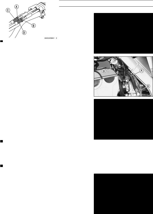
Fuel System
Fuel Hose and Connection Inspection
○The fuel hoses are designed to be used throughout the motorcycle’s life without any maintenance, however, if the motorcycle is not properly handled, the inside the fuel line
•can cause fuel to leak [A] or the hose to burst. Check the fuel hose.
Replace the fuel hose if any fraying, cracks [B] or bulges [C] are noticed.
•Check that the hose [A] are securely connected and
•clamps [B] are tightened correctly.
When installing, route the hose according to Cable, Wire,
•and Hose Routing section in the Appendix chapter. When installing the fuel hose, avoid sharp bending, kinking, flattening or twisting, and route the fuel hose with a minimum of bending so that the fuel flow will not be obstructed.
 Replace the hose if it has been sharply bent or kinked.
Throttle• Grip Free Play Inspection
Check throttle grip free play [B] by lightly turning the throttle grip [A] back and forth.
 If the free play is improper, adjust the throttle cable.
Throttle Grip Free Play |
2 3 mm (0.08 0.12 in.) |
Standard: |
•Check that the throttle grip moves smoothly from full open to close, and the throttle closes quickly and completely in all steering positions by the return spring.
If the throttle grip does not return properly, check the throttle cable routing, grip free play, and cable damage. Then
•lubricate the throttle cable.
Run the engine at the idle speed, and turn the handlebar all the way to the right and left to ensure that the idle speed does not change.
If the idle speed increase, check the throttle cable free play and the cable routing.
Throttle• Grip Free Play Adjustment
Loosen the locknuts [A] [B] at the upper end of the throttle
•cable.
Screw both throttle cable adjuster [C] [D] to give the throt-
•tle grip plenty of play.
Turn out the decelerator adjuster [C] until there is no play
•when the throttle grip is completely closed.
•Tighten the locknut [A].
Turn the accelerator cable adjuster [D] until 2 3 mm
•(0.08 0.12 in.) of throttle grip play is obtained. Tighten the locknut [B].
http://manuals.magnamaniac.com
Loading...