


FH680V
Table of contents
 Loading...
FH451V,FH500V,FH531V
FH601V,FH641V,FH680V
FH721V
4–stroke air cooled v-twin gasoline engine
Service Manual
All rights reserved. No parts of this publication may be reproduced, stored in a retrieval system, or transmitted in any
form or by any means, electronic mechanical photocopying, recording or otherwise, without the prior written permission of
Quality Assurance Department/Consumer Products & Machinery Group/Kawasaki Heavy Industries, Ltd., Japan.
No liability can be accepted for any inaccuracies or omissions in this publication, although every possible care has been
taken to make it as complete and accurate as possible.
The right is reserved to make changes at any time without prior notice and without incurring an obligation to make such
changes to products manufactured previously.
All information contained in this publication is based on the latest product information available at the time of publication.
Illustrations and photographs in this publication are intended for reference use only and may not depict actual model
component parts.
© Kawasaki Heavy Industries, Ltd., 1999, 2000 Third Edition (1) : Nov. 20, 2000 (K)
LIST OF ABBREVIATIONS
A ampere(s) lb pound(s)
ABDC after bottom dead center m meter(s)
AC alternating current min minute(s)
ATDC after top dead center N newton(s)
BBDC before bottom dead center Pa pascal(s)
BDC bottom dead center PS horsepower
BTDC before top dead center psi pound(s) per square inch
C
degree(s) Celsius r revolution
DC direct current rpm revolution(s) per minute
F farad(s) TDC top dead center
F degree(s) Fahrenheit TIR total indicator reading
ft foot, feet V volt(s)
g gram(s) W watt(s)
h hour(s)
ohm(s)
L liter(s)
Read OWNER’S MANUAL before operating.

EMISSION CONTROL INFORMATION
To protect the environment in which we all live, Kawasaki has incorporated crankcase emission (1) and exhaustemission
(2) control systems (EM) in compliance with applicable regulations of the United States Environmental Protection Agency
and California Air Resources Board.
1. Crankcase Emission Control System
A sealed-type crankcase emission control system is used to eliminate blow-by gases. The blow-by
gases are led to the breather chamber through the crankcase. Then, it is led to the air cleaner.
Oil is separated from the gases while passing through the inside of the breather chamber from the
crankcase, and then returned back to the bottom of crankcase.
2. Exhaust Emission Control System
The exhaust emission control system applied to this engine consists of a carburetor and an ignition
system having optimum ignition timing characteristics.
The carburetor has been calibrated to provide lean air/fuel mixture characteristics and optimum fuel
economy with a suitable air cleaner and exhaust system.
TAMPERING WITH EMISSION CONTROL SYSTEM PROHIBITED
Federal law and California State law prohibits the following acts or the causing thereof: (1) the removal or rendering
inoperative by any person other than for purposes of maintenance, repair, or replacement, of any device or element of
design incorporated into any new engine for the purpose of emission control prior to its sale or delivery to the ultimate
purchaser or while it is in use, or (2) the use of the engine after such device or element of design has been removed or
rendered inoperative by any person.
Among those acts presumed to constitute tampering are the acts listed below:
Do not tamper with the original emission related part:
•
Carburetor and internal parts
•
Spark plugs
•
Magneto or electronic ignition system
•
Fuel filter element
•
Air cleaner elements
•
Crankcase
•
Cylinder heads
•
Breather chamber and internal parts
•
Intake pipe and tube
Foreword
This manual is designed primarily for use by trained
mechanics in a properly equipped shop. However, it
contains enough detail and basic information to make
it useful to the owner who desires to perform his own
basic maintenance and repair work. A basic knowledge
of mechanics, the proper use of tools, and workshop
procedures must be understood in order to carry out
maintenance and repair satisfactorily. Whenever the
owner has insufficient experience or doubts as to his
ability to do the work, all adjustments, maintenance, and
repair should be carried out only by qualified mechanics.
In order to perform the work efficiently and to avoid
costly mistakes, read the text, thoroughly familiarize
yourself with the procedures before starting work, and
then do the work carefully in a clean area. Whenever
special tools or equipment are specified, do not use
makeshift tools or equipment. Precision measurements
can only be made if the proper instruments are used,
and the use of substitute tools may adversely affect safe
operation.
To get the longest life out of your engine:
•
Follow the Periodic Maintenance Chart in the Service
Manual.
•
Be alert for problems and non-scheduled maintenance.
•
Use proper tools and genuine Kawasaki engine parts.
Genuine parts provided as spare parts are listed in the
Parts Catalog.
•
Follow the procedures in this manual carefully. Don’t
take shortcuts.
•
Remember to keep complete records of maintenance
and repair with dates and any new parts installed.
How to Use This Manual
In preparing this manual, we divided the product into
its major systems. These systems became the manual’s
chapters. All information for a particular system from
adjustment through disassembly and inspection is located
in a single chapter.
The Quick Reference Guide shows you all of the
product’s system and assists in locating their chapters.
Each chapter in turn has its own comprehensive Table of
Contents.
The Periodic Maintenance Chart is located in the
General Information chapter. The chart gives a time
schedule for required maintenance operations.
If you want spark plug information, for example, go to
the Periodic Maintenance Chart first. The chart tells you
how frequently to clean and gap the plug. Next, use the
Quick Reference Guide to locate the Electrical System
chapter. Then, use the Tableof Contents on the first page
of the chapter to find the Spark Plug section.
Whenever you see these WARNING and CAUTION
symbols, heed their instructions! Always follow safe
operating and maintenance practices.
This warning symbol identifies special instruc-
tions or procedures which, if not correctly fol-
lowed, could result in personal injury, or loss of
life.
CAUTION
This caution symbol identifies special instruc-
tions or procedures which, if not strictly ob-
served, could result in damage to or destruction
of equipment.
This manual contains four more symbols (in addition to
WARNING and CAUTION) which will help you distinguish
different types of information.
NOTE
This note symbol indicates points of particular in-
terest for more efficient and convenient operation.
•
Indicates a procedural step or work to be done.
Indicates a procedural sub-step or how to do the work
of the procedural step it follows. It also precedes the
text of a WARNING, CAUTION, or NOTE.
Indicates a conditionalsteporwhataction to take based
on the results of the test or inspection in the procedural
step or sub-step it follows.
In most chapters an exploded view illustration of the
system components follows the Table of Contents. In
these illustrations you will find the instructions indicating
which parts require specified tightening torque, oil, grease
or a locking agent during assembly.

GENERAL INFORMATION 1-1
General Information
Table of Contents
1
Before Servicing.................................................................................................................................................................1-2
Model Identification............................................................................................................................................................1-4
General Specifications.......................................................................................................................................................1-6
Periodic Maintenance Chart...............................................................................................................................................1-7
Torque and Locking Agent.................................................................................................................................................1-9
Special Tools....................................................................................................................................................................1-13

1-2 GENERAL INFORMATION
Before Servicing
Before starting to service the engine, carefully read the applicable section to eliminate unnecessary work. Photographs,
diagrams, notes, cautions, warnings, and detailed descriptions have been included wherever necessary. Nevertheless,
even a detailed account has limitations, a certain amount of basic knowledge is required for successful work.
Especially note the following:
(1) Dirt
Before removal and disassembly, clean the engine. Any dirt entering the engine, carburetor, or other parts, will
work as an abrasive and shorten the life of engine. For the same reason, before installing a new part, clean off any
dust or metal filings.
(2) Battery Ground
Remove the ground (—) lead from the battery before performing any disassembly operations on the equipment.
This prevents:
(a) the possibility of accidentally turning the engine over while partially disassembled.
(b) sparks at electrical connections which will occur when they are disconnected.
(c) damage to electrical parts.
(3) Tightening Sequence
Generally, when installing a part with several bolts, nuts, or screws, start them all in their holes and tighten them to
a snug fit. Then tighten them evenly, in a staggered sequence. This is to avoid distortion of the part and/or causing
gas or oil leakage. Conversely when loosening the bolts, nuts, or screws, first loosen all of them by about a quarter
of a turn and then remove them. Where there is a tightening sequence indication in this Service Manual, the bolts,
nuts, or screws must be tightened in the order and method indicated.
(4) Torque
When torque values are given in this Service Manual, use them. Either too little or too much torque may lead to
serious damage. Use a good quality, reliable torque wrench.
(5) Force
Common sense should dictate how much force is necessary in assembly and disassembly. If a part seems especially
difficult to remove or install, stop and examine what may be causing the problem. Whenever tapping is necessary, tap
lightly using a wooden or plastic-faced mallet. Use an impact driver for screws (particularly for the removal of screws
held by a locking agent) in order to avoid damaging the heads.
(6) Edges
Watch for sharp edges, especially during major engine disassembly and assembly. Protect your hands with gloves
or a piece of thick cloth when lifting the engine or turning it over.
(7) High-Flash Point Solvent
A high-flash point solvent is recommended to reduce fire danger. A commercial solvent commonly available in North
America is Standard solvent (generic name). Always follow manufacturer and container directions regarding the use
of any solvent.
(8) Gasket, O-Ring
Do not reuse a gasket or O-ring once it has been in service. The mating surfaces around the gasket should be
free of foreign matter and perfectly smooth to avoid oil or compression leaks.
(9) Liquid Gasket, Non-Permanent Locking Agent
Follow manufacturer’s directions for cleaning and preparing surfaces where these compounds will be used. Apply
sparingly. Excessive amounts may block engine oil passages and cause serious damage. An example of a non-
permanent locking agent commonly available in North America is Loctite Lock’n Seal (Blue).
(10) Press
A part installed using a press or driver, such as a journal, should first be coated with oil on its outer or inner
circumference so that it will go into place smoothly.
(11) Ball Bearing
When installing a ball bearing, the bearing race which is affected by friction should be pushed by a suitable driver.
This prevents severe stress on the balls and races, and prevents races and balls from being dented. Press a ball
bearing until it stops at the stop in the hole or on the shaft.
(12) Oil Seal and Grease Seal
Replace any oil or grease seals that were removed with new ones, as removal generally damages seals.
When pressing in a seal which has manufacturer’s marks, press it in with the marks facing out. Seals should be
pressed into place using a suitable driver, which contacts evenly with the side of seal, until the face of the seal is even
with the end of the hole.
(13) Seal Guide
A seal guide is required for certain oil or grease seals during installation to avoid damage to the seal lips. Before
a shaft passes through a seal, apply a little oil, preferably high temperature grease on the lips to reduce rubber to
metal friction.
(14) Circlip, Retaining Ring
Replace any circlips and retaining rings that were removed with new ones, as removal weakens and deforms them.
When installing circlips and retaining rings, take care to compress or expand them only enough to install them and
no more.
GENERAL INFORMATION 1-3
Before Servicing
(15) Cotter Pin
Replace any cotter pins that were removed with new ones, as removal deforms and breaks them.
(16) Lubrication
Engine wear is generally at its maximum while the engine is warming up and before all the rubbing surfaces have
an adequate lubricative film. During assembly, oil or grease (whichever is more suitable) should be applied to any
rubbing surface which has lost its lubricative film. Old grease and dirty oil should be cleaned off. Deteriorated grease
has lost its lubricative quality and may contain abrasive foreign particles.
Don’t use just any oil or grease. Some oils and greases in particular should be used only in certain applications and
may be harmful if used in an application for which they are not intended. This manual makes reference to molybdenum
disulfide grease (MoS2) in the assembly of certain engine parts. Always check manufacturer recommendations before
using such special lubricants.
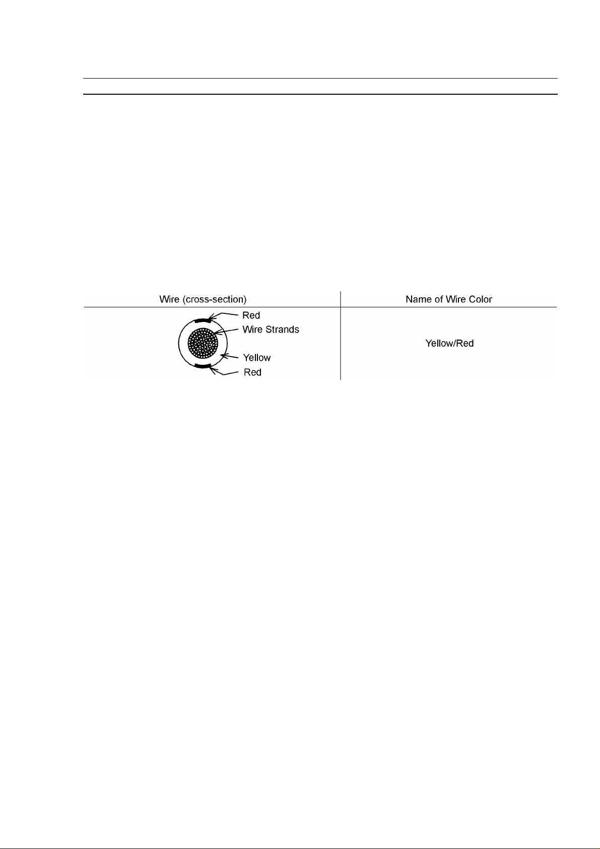
(17) Electrical Wires
All the electrical wires are either single-color or two-color and, with only a few exceptions, must be connected to
wires of the same color. On any of the two-color wires there is a greater amount of one color and a lesser amount of
a second color, so a two-color wire is identified by first the primary color and then the secondary color. For example,
a yellow wire with thin red stripes is referred to as a "yellow/red" wire; it would be a "red/yellow" wire if the colors were
reversed to make red the main color.
(18) Replacement Parts
When there is a replacement instruction, replace these parts with new ones every time they are removed. There
replacement parts will be damaged or lose their original function once removed.
(19) Inspection
When parts have been disassembled, visually inspect these parts for the following conditions or other damage. If
there is any doubt as to the condition of them, replace them with new ones.
Abrasion Crack Hardening Warp
Bent Dent Scratch Wear
Color change Deterioration Seizure
(20) Specifications
Specification terms are defined as follows:
"Standards" show dimensions or performances which brand-new parts or systems have.
"Service Limits" indicate the usable limits. If the measurement shows excessive wear or deteriorated performance,
replace the damaged parts.
1-4 GENERAL INFORMATION
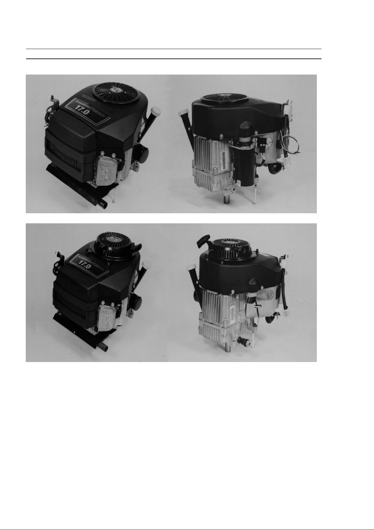
Model Identification
Electric Starter Model-FH500V
Recoil Starter Model-FH500V
Cylinder Number Designation:
No.1 Cylinder is the left-hand cylinder viewed from the air cleaner.
No.2 Cylinder is the right-hand cylinder viewed from the air cleaner.

GENERAL INFORMATION 1-5
Model Identification
Electric Starter Model-FH680V

1-6 GENERAL INFORMATION
General Specifications
Items
FH451V, FH500V, FH531V FH601V, FH641V, FH680V FH721V
Type of engine
Forced air-cooled, vertical shaft, OHV, 4-stroke gasoline engine.
Cylinder layout 90 V-Twin
Bore x Stroke 68 mm x 68 mm (2.68 in x 2.68 in) 75.2 mm x 76 mm (2.96 in x 2.99 in)
Piston displacement 494 mL (30.1 cu. in) 675 mL (41.19 cu.in)
Direction of rotation Counterclockwise facing the PTO shaft
Compression release Automatic compression release
Low idle speed 1550 rpm
Fast idle speed 3600 rpm
Ignition system Transistorized-fly wheel magneto
RFI Per Canada and U.S.A. requirements
Starting system Electric starter and/or recoil starter
Charging system 12 V - 13 amps with regulator
Spark plug CHAMPION RCJ8Y NGK BPR4ES
Carburetor Float type, fixed main jet Float type, fixed main jet, two barrel
Fuel pump Diaphragm type pulse pump
Air cleaner Dual stage element, dry type
Governor Flyweight all speed governor
Lubrication system Pressure feed by positive displacement pump
Oil filter Cartridge type full flow filter
Oil pressuer switch ON-OFF switch
Oil capacity
(when engine is
completely dry)
1.8 L (1.9 US-qt) 1.9 L
(2.0 US-qt)
Cooling system Forced air cooling by fan
Dimensions (L x W x H ) 425 mm x 359 mm x 324 mm 458 mm x 430 mm x 381mm
Electric starter model (16.7 in x 14.1 in x 12.8 in) (18.0 in x 16.9 in x 15.0 in)
425 mm x 359 mm x 361 mm
Recoil starter model (16.7 in x 14.1 in x 14.2 in)
Dry weight
Electric starter model 34 kg (75 lb) 40.5 kg (89.3 lbs) 41.2 kg
(90.8 lbs)
Recoil starter model 32 kg (71 lb)
Specifications are subject to change without notice.

GENERAL INFORMATION 1-7
Periodic Maintenance Chart
To ensure satisfactory operation over an extended period of time, any engine requires normal maintenance regular
intervals. The Periodic Maintenance Chart below shows periodic inspection and maintenance items and suitable intervals.
The bullet mark (•) designates that the corresponding item should be performed at that interval.
Some adjustments require the use of special tools or other equipment. An electronic tachometer will facilitate setting
idle and running speeds.
FH451V, FH500V, FH531V
OPERATION INTERVAL
Daily First
8hr.
Every
25 hr.
Every
50 hr.
Every
100 hr.
Every
200 hr.
Every
300 hr.
Check or clean air intake screen
•
Check and add engine oil
•
Check for fuel and oil leakage
•
Check for loose or lost nut and screw
•
Check battery electrolyte level
•
Clean air cleaner foam element (1)
•
Clean air cleaner paper element (1)
•
Clean dust and dirt from cylinder and
cylinder head fins (1)
•
Tighten nut and screws
•
Change engine oil
• •
Clean and re-gap spark plugs
•
Change Oil filter
•
Change air cleaner paper element (1)
•
Check and adjust vlave clearance
•
Clean and lap valve seating surface
•
Clean combustion chamber
•
(1): Service more frequently under dusty conditions.
: These items must be performed with the proper tools. See your authorized Kawasaki Engine Dealer for service,
unless you have the proper equipment and mechanical proficiency.

1-8 GENERAL INFORMATION
Periodic Maintenance Chart
FH601V, FH641V, FH680V, FH721V
OPERATION
INTERVAL
Daily First
8hr.
Every
25 hr.
Every
50 hr.
Every
100 hr.
Every
200 hr.
Every
300 hr.
Check or clean air intake screen
•
Check and add engine oil
•
Check for fuel and oil leakage
•
Check for loose or lost nut and screw
•
Check battery electrolyte level
•
Clean air cleaner foam element (1)
•
Clean air cleaner paper element (1)
•
Clean dust and dirt from cylinder and
cylinder head fins (1)
•
Tighten nut and screws
•
Change engine oil
• •
Clean and re-gap spark plugs
•
Check and clean oil cooler fins (FH721V
engines).
•
Change Oil filter
•
Change air cleaner paper element (1)
•
Check and adjust vlave clearance
•
Clean and lap valve seating surface
•
Clean combustion chamber
•
(1): Service more frequently under dusty conditions.
: These items must be performed with the proper tools. See your authorized Kawasaki Engine Dealer for service,
unless you have the proper equipment and mechanical proficiency.
GENERAL INFORMATION 1-9
Torque and Locking Agent
The following tables lists the tightening torque for the major fasteners, and the parts requiring use of a non-permanent
locking agent or liquid gasket.
Letters used in the "Remarks" column mean:
L:Apply a non-permanent locking agent to the threads.
M:Apply a molybdenum disulfide lubricant (grease or oil) to the threads, seated surface, or washer.
O:Apply an oil to the threads, seated surface, or washer.
S:Tighten the fasteners following the specified sequence.
SS : Apply silicone sealant.
FH451V, FH500V, FH531V
FH451V, FH500V, FH531V
Fastener
Torque
Remarks
N
1
m
kg
1
m ft
1
lb
Fuel System:
Choke Valve Screw 0.7 0.07 6in
1
lb
Throttle Valve Screws 1.0 0.10 9in
1
lb
Pilot Jet 1.7 0.17 15 in
1
lb
Main Jet 0.7 0.07 6in
1
lb
Main Air Jet 0.7 0.07 6in
1
lb
Main Nozzle 2.0 0.20 17 in
1
lb
Pilot Air Jet 0.7 0.07 6in
1
lb
Drain Screw (Carburetor) 1.3 0.13 11 in
1
lb
Earth Lead Screw 3.4 0.35 30 in
1
lb
(Carburetor Side)
Fuel Shut Off Solenoid Valve 6.9 0.70 61 in
1
lb
(Carburetor)
Float Chamber Mounting Screw 8.8 0.90 78 in-lb
(Carburetor)
Governor Arm Clamp Nut 7.8 0.8 69 in
1
lb
Governor Shaft Plate Screws 2.0 0.20 18 in-lb
Holder Plate Nuts (Air Cleaner, 5.9 0.60 52 in
1
lb
Carburetor Mounting)
Intake Manifold Mounting Bolts 5.9 0.6 52 in
1
lb
Cleaner Body Mounting Screws 3.4 0.35 30 in
1
lb
Control Panel Mounting Bolts 5.9 0.6 52 in
1
lb
Cooling System:
Engine-shoroud Bolt (M8) 15 1.5 11
Engine-shoroud Bolts (M6) 5.9 0.6 52 in
1
lb
Plug Bolt (Engine-shroud) 5.9 0.6 52 in
1
lb
Plug Screw (Engine-shroud) 3.4 0.35 30 in
1
lb
Engine Top End
Cylinder Head Bolts 25 2.6 19.0 =S
Valve Clearance Lock Screws 6.9 0.70 61 in
1
lb
Connecting Rod Big End 5.9 0.60 52 in
1
lb =O
Cap Bolts
Rocker Arm Bolts 28 2.8 20
Rocker Cover Mounting Bolts 5.9 0.6 52 in
1
lb
Exhaust Pipe Flange Nuts 15 1.5 11
Spark Plugs 22 2.2 16
1-10 GENERAL INFORMATION
Torque and Locking Agent
FH451V, FH500V, FH531V
Fastener
Torque
Remarks
N
1
m kg
1
m ft
1
lb
Lubrication System:
Engine Drian Plugs (Plastic)
6.9 0.70 61 in
1
lb
Engine Drain Plug (Metal) 20 2.0 14.5
Engine Drain Plug Joint (Plastic) 17 1.7 12.0
Engine Drain Plug Joint (Metal) 39 4.0 29
Oil Pressure Switch
9.8 1.0 87 in
1
lb
=SS
Oil Passage Plug 3.9 0.40 35 in
1
lb
Oil Pump Cover Plate Mounting Bolts 5.9 0.6 52 in
1
lb
Oil Filter in the text
Camshaft/Crankshaft:
Crankcase Cover Bolts 25 2.6 19.0 =S
Breather Chamber Cover Bolts 5.9 0.6 52 in
1
lb
Electrical System:
Starter Coil Screws 3.4 0.35 30 in
1
lb
Flywheel Bolt 56 5.7 41
Fan Housing Bolts 5.9 0.6 52 in
1
lb
Screen Bolts 5.9 0.6 52 in
1
lb
Regulator Screws 3.4 0.35 30 in
1
lb
Ignition Coil Bolts (Studs) 7.8 0.8 69 in
1
lb
Ignition Coil Bolts (Bolts) 5.9 0.6 52 in
1
lb
Starter Motor Mounting Bolts 15 1.5 11
Recoil Starter Mounting Nuts 5.9 0.6 52 in
1
lb
Recoil Starter Retainier Screw 7.8 0.8 69 in
1
lb
Spark Plugs 15 1.5 11.0
GENERAL INFORMATION 1-11
Torque and Locking Agent
FH601V, FH641V, FH680V, FH721V
FH601V, FH641V, FH680V, FH721V
Fasteners
Torque
Remarks
N
1
m
kg
1
m ft
1
lb
Fuel System:
Choke Valve Screw 1.0 0.10 8.9 in
1
lb
=L
Throttle Valve Screws
1.0 0.10 8.9 in
1
lb
=L
Pilot Jet – – –
Main Jet – – -
Plug, Main Jet 19 1.9 14
Main Nozzle – – –
Main Air Jet – – –
Pilot Air Jet – – –
Drain Screw(Carburetor) 2.0 0.2 18 in
1
lb
Earth lead screw – – –
(Carburetor Side)
Fuel Shut Off Solenoid Valve (Carburetor) 20 2.0 15
Float Chamber Mounting 3.9 0.4 35 in
1
lb
Screw(Carburetor)
Governor Arm Clamp Nut 7.8 0.8 69 in
1
lb
Governor Shaft Plate Screws 2.0 0.2 18 in
1
lb
Intake Pipe Mounting Bolts and Nuts 5.9 0.6 52 in
1
lb
Intake Manifold Mounting Bolts 5.9 0.6 52 in
1
lb
Cleaner Body Mounting Screws – – –
Control Panel Mounting Bolts 5.9 0.6 52 in
1
lb
Cooling System:
Engine-shroud Bolt (M8) 15 1.5 11
Engine-shroud Bolts (M6) 5.9 0.6 52 in
1
lb
Plug Bolt (Engine-shroud) – – –
Plug Screw (Engine-shroud) 3.4 0.35 30 in
1
lb
Engine Top End:
Cylinder Head Bolts 25 2.6 19 =S
Valve Clearance Lock Screws 6.9 0.7 61 in
1
lb
Connecting Rod Big End 21 2.1 15 =O
Cap Bolts
Rocker Arm Bolts 28 2.8 20
Rocker Cover Mounting Bolts 5.9 0.6 52 in-lb
Exhaust Pipe Flange Nuts 15 1.5 11
Spark Plugs 22 2.2 16
1-12 GENERAL INFORMATION
Torque and Locking Agent
FH601V, FH641V, FH680V, FH721V
Fastener
Torque
Remarks
N
1
m kg
1
m ft
1
lb
Lubrication System:
Engine Drian Plugs (Plastic)
6.9 0.7 61 in
1
lb
Engine Drain Plug (Metal) 20 2.0 14.5
Engine Drain Plug Joint (Plastic) 17 1.7 12
Engine Drain Plug Joint (Metal) 39 4.0 29
Oil Pressure Switch
9.8 1.0 87 in
1
lb
=SS
Oil Passage Plug 3.9 0.40 35 in
1
lb
Oil Pump Cover Plate Mounting Bolts 5.9 0.6 52 in
1
lb
Oil Filter in the text
Oil Cooler Mounting Joint 44 4.5 33
Camshaft/Crankshaft:
Crankcase Cover Bolts
25 2.6 19.0 =S
Breather Chamber Cover Bolts 5.9 0.6 52 in
1
lb
Electrical System:
Starter Coil Screws 3.4 0.35 30 in
1
lb
Flywheel Bolt 56 5.7 41
Fan Housing Bolts 5.9 0.6 52 in
1
lb
Screen Bolts 5.9 0.6 52 in
1
lb
Regulator Screws 3.4 0.35 30 in
1
lb
Ignition Coil Bolts (Studs) 7.8 0.8 69 in
1
lb
Ignition Coil Bolts (Bolts) 5.9 0.6 52 in
1
lb
Starter Motor Mounting Bolts 15 1.5 11
Recoil Starter Mounting Nuts – – –
Recoil Starter Retainier Screw – – –
Spark Plugs 22 2.2 16
L:Apply a non-permanent locking agent to the threads.
M:Apply a molybdenum disulfide lubricant (grease or oil) to the threads, seated surface, or washer.
O:Apply an oil to the threads, seated surface, or washer.
S:Tighten the fasteners following the specified sequence.
SS : Apply silicone sealant.
The table below, relating tightening torque to thread diameter, lists the basic torque for the bolts and nuts. Use this
table for only the bolts and nuts which do not require a specific torque value. All of the values are for use with dry
solvent-cleaned threads.
Basic Torque for General Fasteners
Threads dia
Torque
(mm) N
1
m kg
1
m ft
1
lb
4 2.0 0.2 17 in
1
lb
5 3.4 0.35 30 in
1
lb
6 5.9 0.6 52 in-lb
8 15 1.5 11
GENERAL INFORMATION 1-13
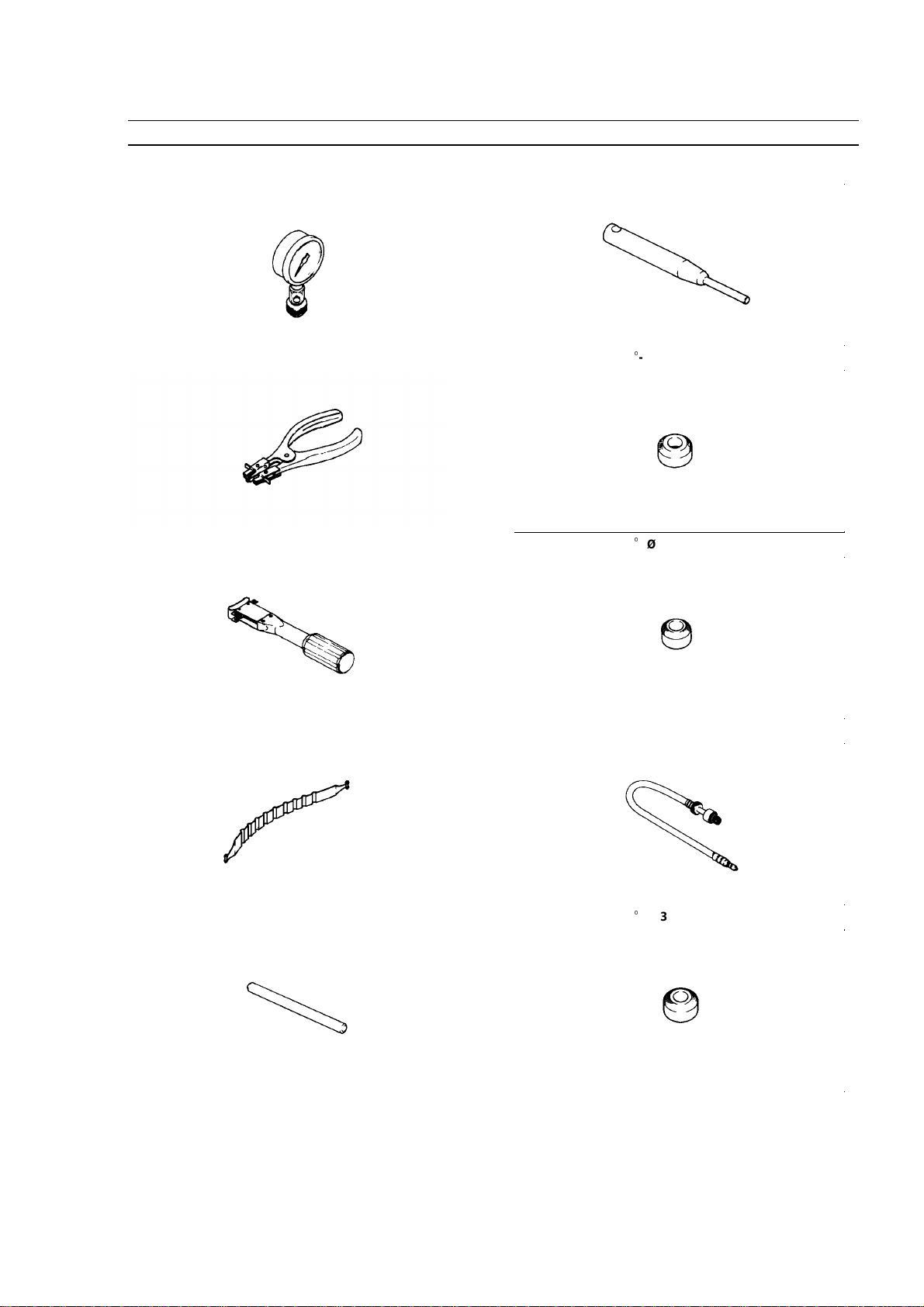
Special Tools
Compression Gauge: 57001–221
Piston Ring Pliers: 57001–115
Piston Ring Compression Grip: 57001–1095
Piston Ring Compression Belt, Ø67 -Ø79: 57001–1097
Valve Seat Cutter Holder Bar: 57001–1128
Valve Seat Cutter Holder Ø6: 57001–1360
Valve Seat Cutter, 45
- Ø35.0: 57001–1116
Valve Seat Cutter, 30
- Ø 33.0: 57001–1199
Compression Gauge Adapter M14 x 1.25: 57001–1159
Valve Seat Cutter, 30
- Ø 30.0: 57001–1120
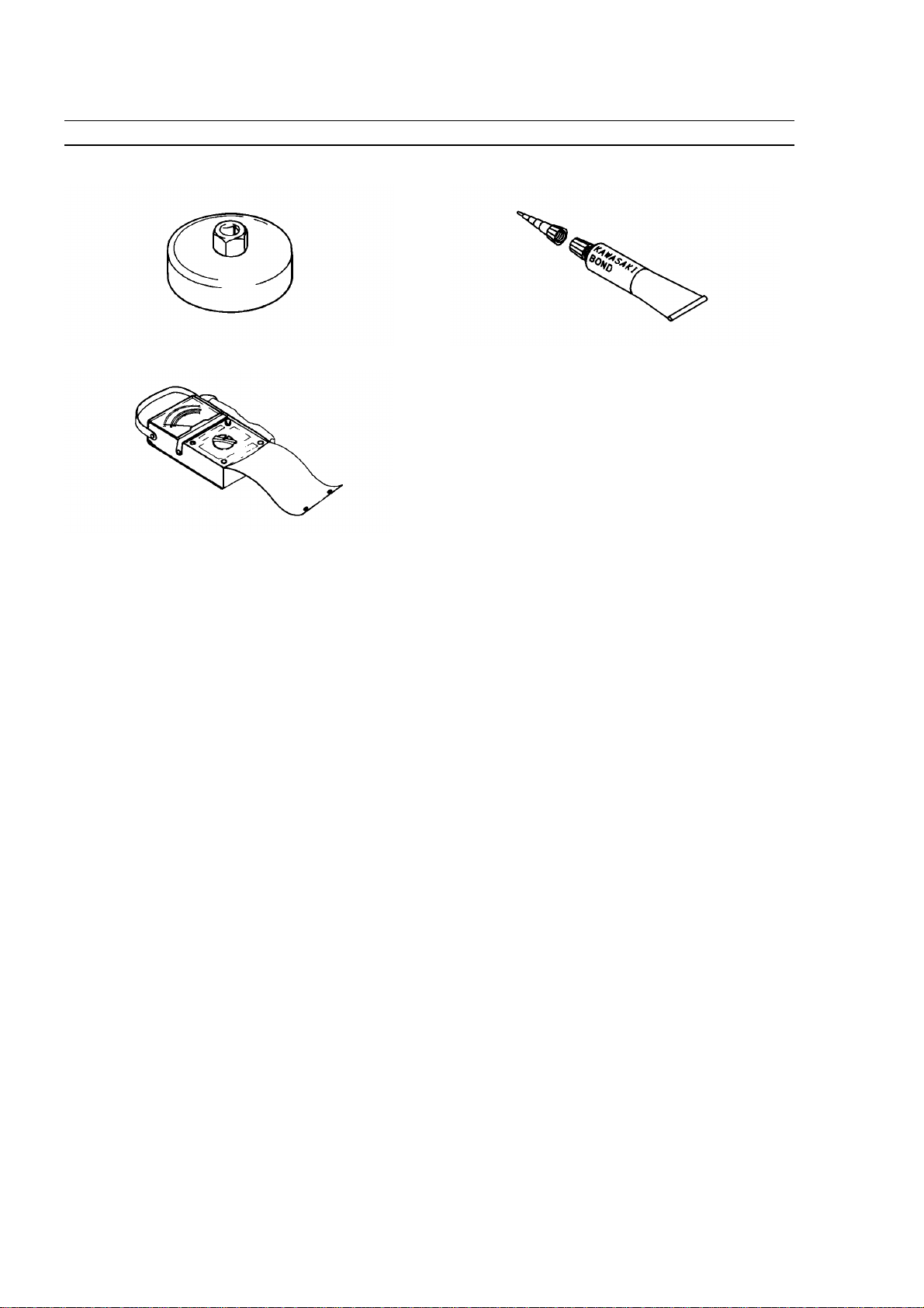
1-14 GENERAL INFORMATION
Special Tools
Oil Filter Wrench : 57001–1249
Hand Tester: 57001–1394
Kawasaki Bond (Silicone Sealant) : 56019–120

FUEL SYSTEM 2-1
Fuel System
Table of Contents
2
Exploded View.............................................................2-2
Specifications...............................................................2-8
Governor Link Mechanism..........................................2-9
Control Panel Assembly Removal........................2-9
Control Panel Assembly Installation.....................2-9
Governor Arm Removal........................................2-9
Governor Arm Installation...................................2-10
Governor Assembly Removal.............................2-10
Governor Assembly Installation..........................2-10
Governor Assembly Inspection...........................2-11
Governor Shaft Removal....................................2-11
Governor Shaft Installation.................................2-11
Carburetor..................................................................2-12
Fuel and Air Flow...............................................2-12
Fuel Shut Off Solenoid Valve (Electric Starter
Model).................................................................2-13
Low Idle Speed Adjustment................................2-13
High Idle Speed Adjustment...............................2-13
High Altitude Operation......................................2-14
Main Jet Replacement........................................2-14
Fuel system Cleanliness Inspection...................2-15
Carburetor Removal............................................2-16
Carburetor Installation........................................2-16
Carburetor Disassembly/Assembly - FH451V, 500V,
531V...................................................................2-17
Carburetor Disassembly/Assembly-FH601V, 641V,
680V, 721V..........................................................2-18
Carburetor Cleaning...........................................2-19
Carburetor Inspection.........................................2-20
Fuel Shut-Off Solenoid Valve Test (ElectricStarter
Model).................................................................2-21
Intake Manifold..........................................................2-22
Intake Manifold Removal....................................2-22
Intake Manifold Installation.................................2-22
Intake Manifold Inspection..................................2-23
Fuel Pump, Fuel Filter...............................................2-24
Fuel Pump Inspection.........................................2-24
Fuel Filter Inspection..........................................2-24
Air Cleaner.................................................................2-25
Element Removal - FH451V, 500V, 531V..........2-25
Element Removal - FH601V, 641V, 680V, 721V 2-25
Element Installation............................................2-25
Element Cleaning and Inspection - FH451V, 500V,
531V...................................................................2-25
Element Cleaning and Inspection - FH601V, 641V,
680V, 721V ........................................................2-26
Cleaner Body Removal - FH451V, 500V, 531V..2-26
Cleaner Body Removal - FH601V, FH641V, FH680V,
FH721V .............................................................2-27
Cleaner Body Installation - FH451V, 500V, 531V2-27
Cleaner Body Installation - FH601V, 641V, 680V,
721V ..................................................................2-27
Housing (Case and Body) Inspection.................2-28
2-2 FUEL SYSTEM
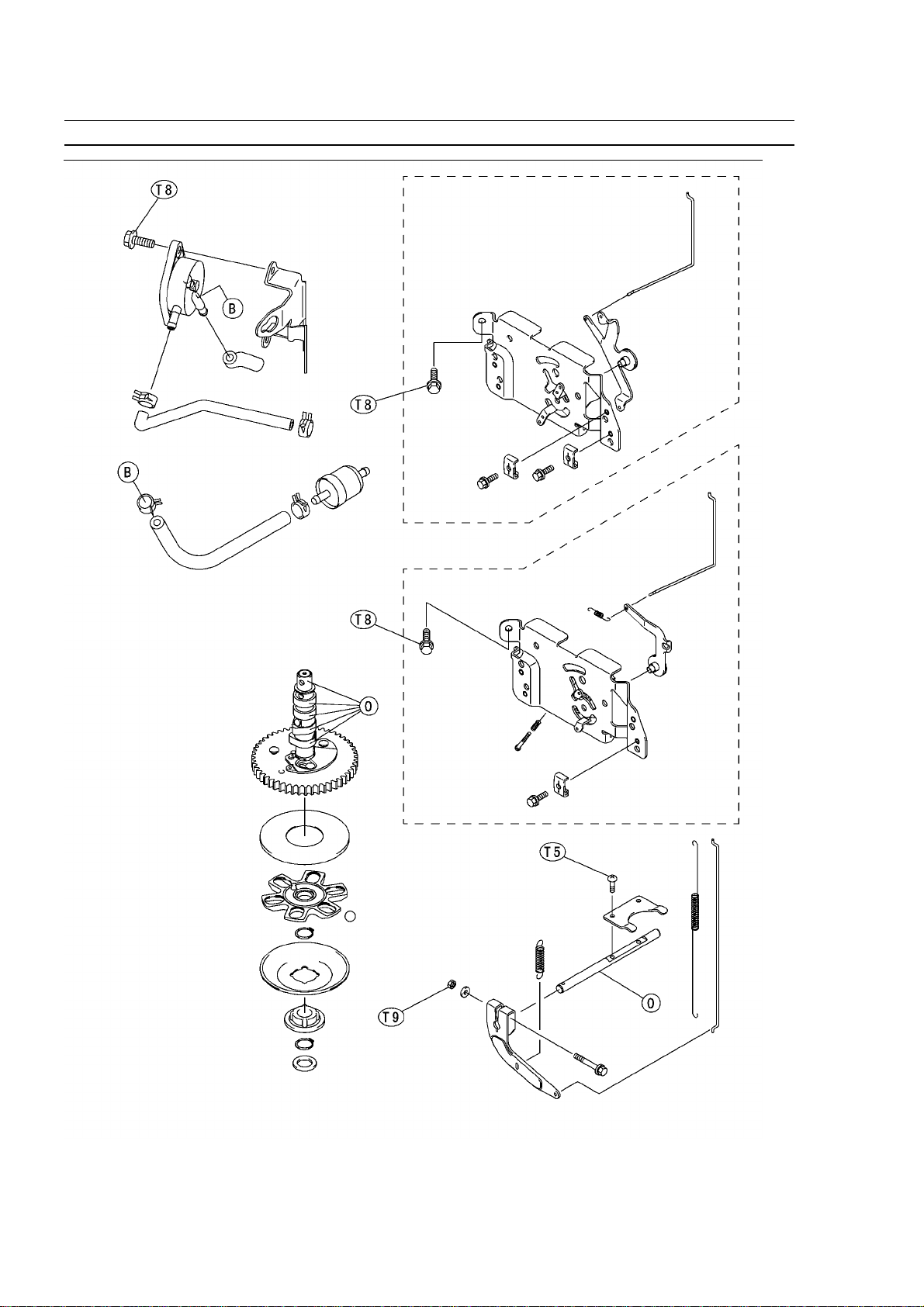
Exploded View
[FH451V, FH500V, FH531V]

FUEL SYSTEM 2-3
Exploded View
[FH451V, FH500V, FH531V]
1. Pilot Screw
2. Pilot Air Jet
3. Main Air Jet
4. Main Jet
5. Pilot Jet
6. Solenoid Valve
T1: 0.7 N
1
m (0.07 kg
1
m, 6 in
1
lb)
T2: 1.0 N
1
m (0.10 kg
1
m, 9 in
1
lb)
T3: 1.3 N
1
m (0.13 kg
1
m, 11 in
1
lb)
T4: 1.7 N
1
m (0.17 kg
1
m, 15 in
1
lb)
T5: 2.0 N
1
m (0.20 kg
1
m, 17 in
1
lb)
T6: 3.4 N
1
m (0.35 kg
1
m, 30 in
1
lb)
T7: 3.9 N
1
m (0.40 kg
1
m, 35 in
1
lb)
T8: 6.9 N
1
m (0.70 kg
1
m, 61 in
1
lb
T9: 7.8 N
1
m (0.80 kg
1
m, 69 in
1
lb)
T10: 8.8 N
1
m (0.90 kg
1
m, 78 in
1
lb)
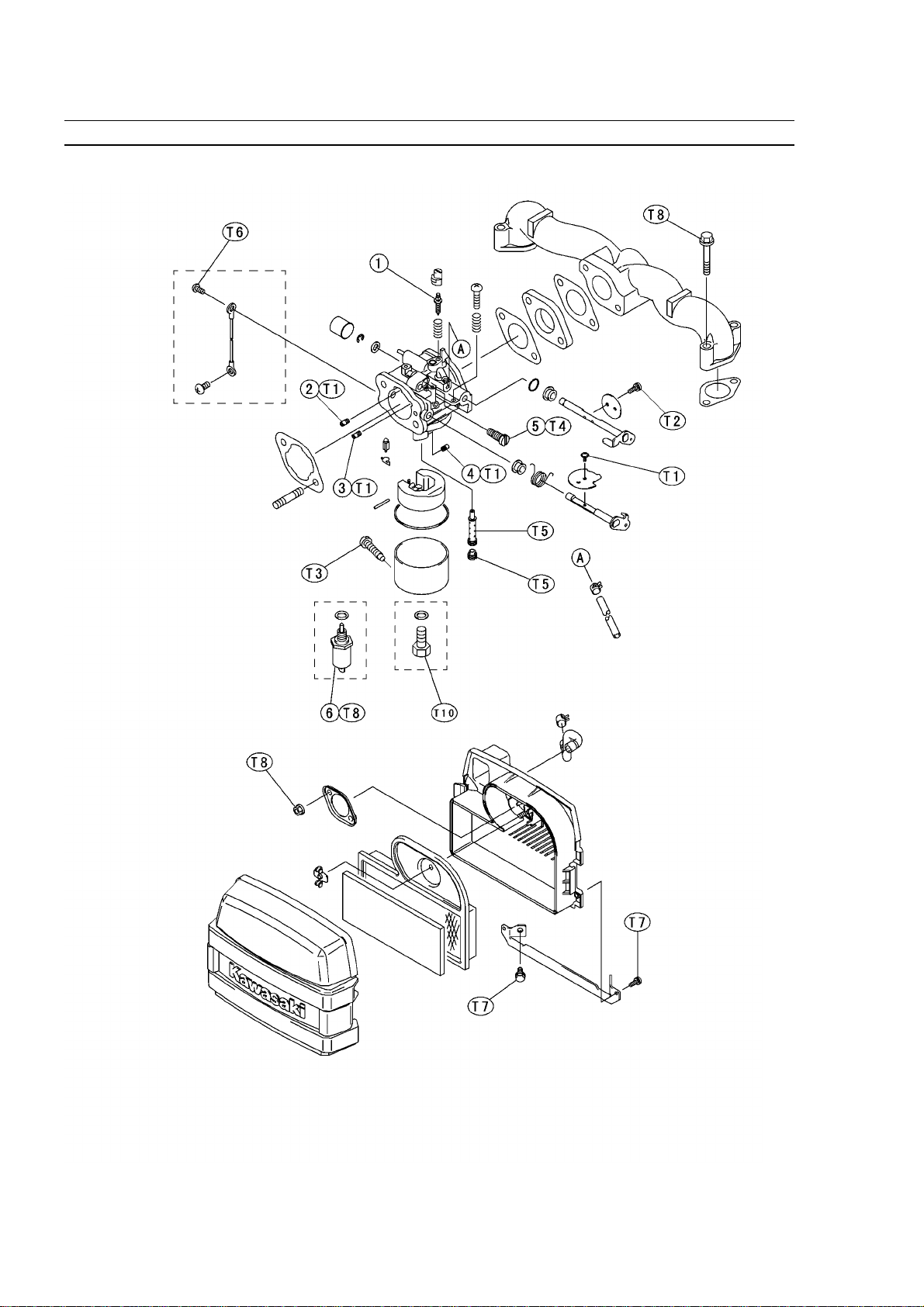
2-4 FUEL SYSTEM
Exploded View
[FH601V, FH641V, FH680V, FH721V]

FUEL SYSTEM 2-5
Exploded View
[FH601V, FH641V, FH680V, FH721V]
1. Pilot Screw
2. Pilot Air Jet
3. Main Air Jet
4. Main Jet
5. Pilot Jet
6. Solenoid Valve
T1: 1.0 N
1
m (0.10 kg
1
m, 9 in
1
lb)
T2: 3.9 N
1
m (0.40 kg
1
m, 35 in
1
lb)
T3: 2.0 N
1
m (0.20 kg
1
m, 18 in
1
lb)
T4: 19 N
1
m (1.9 kg
1
m, 14 ft
1
lb)
T5: 20 N
1
m (2.0 kg
1
m, 15 ft
1
lb)
T6: 6.9 N
1
m (0.70 kg
1
m, 61 in
1
lb)
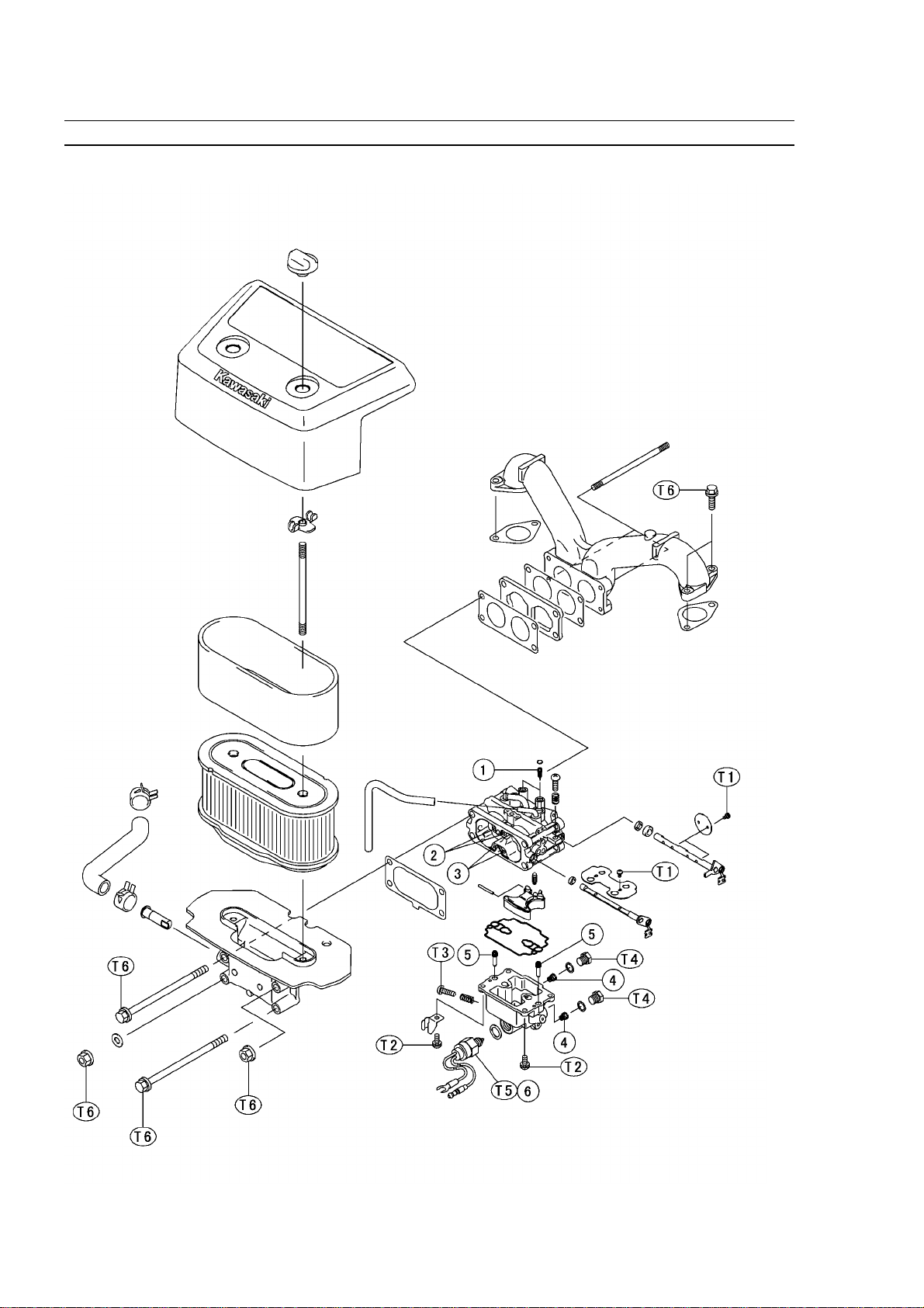
2-6 FUEL SYSTEM
Exploded View

FUEL SYSTEM 2-7
Exploded View
[FH451V, FH500V, FH531V]
T5: 2.0 N
1
m (0.20 kg
1
m , 17 in
1
lb)
T8: 5.9 N
1
m (0.60 kg
1
m , 52 in
1
lb)
T9: 7.8 N
1
m (0.80 kg
1
m , 69 in
1
lb)
[FH601V, FH641V, FH680V, FH721V]
T5: 2.0 N
1
m (0.20 kg
1
m , 17 in
1
lb)
T8: 5.9 N
1
m (0.60 kg
1
m , 52 in
1
lb)
T9: 7.8 N
1
m (0.80 kg
1
m , 69 in
1
lb)
O: Apply engine oil.
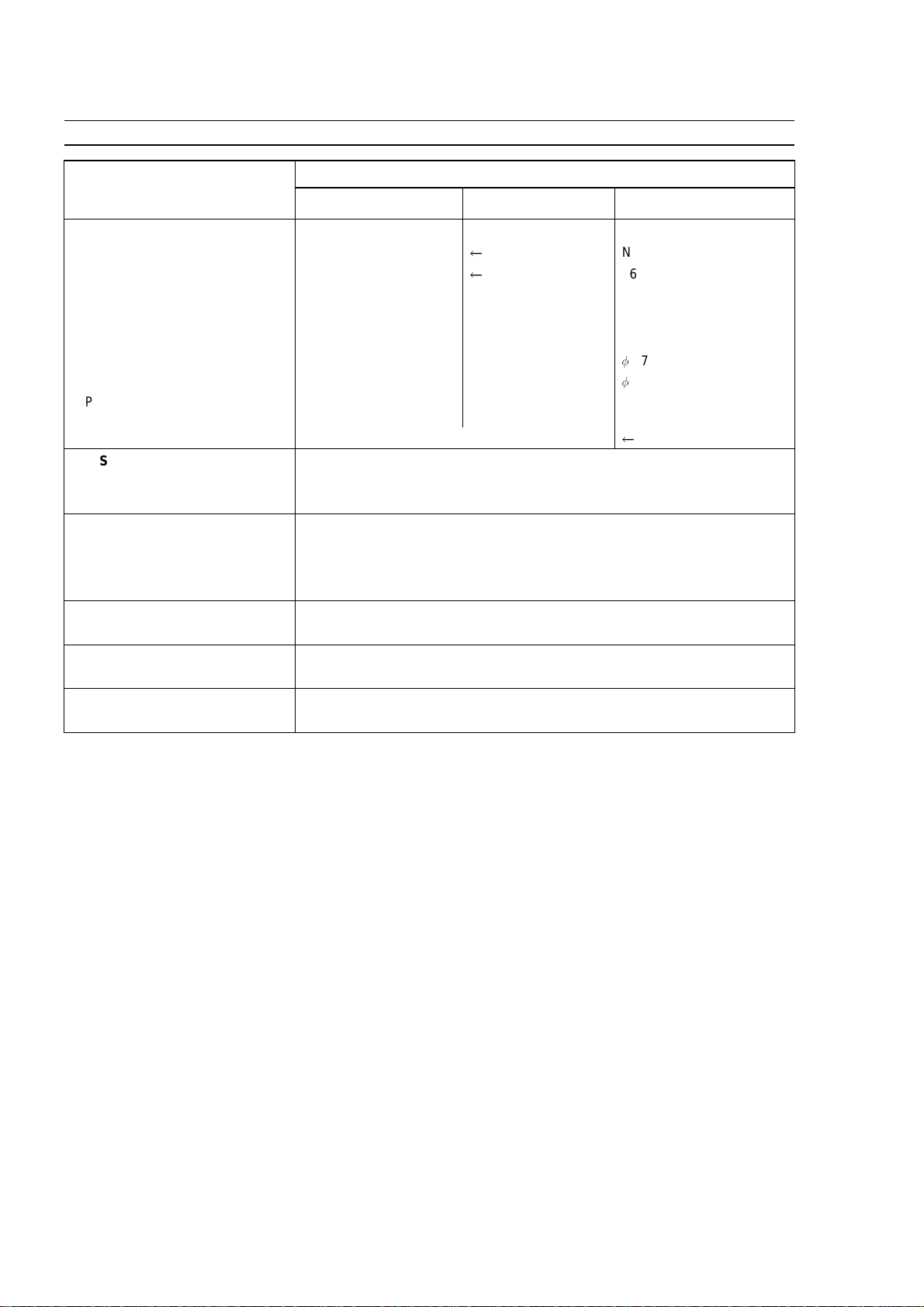
2-8 FUEL SYSTEM
Specifications
Standard
Item
FH451V, FH500V,
FH531V
FH601V, FH641V, FH680V,
FH721V
Caburetors Specifications:
Make/ type MIKUNI B24T1
Nikki 621266
Throttle bore diameter 24 mm (0.94 in.)
26 mm (1.02 in.)
Venturi diameter 16 mm (0.63 in.) 18 mm (0.71 in.) 21 mm (0.83 in.)
Main Jet (MJ) #125 #116.3 L: #136, R: #140
Pilot jet (PJ) #48.8 #43.8 L: #46, R: #44
Main air jet (MAJ) ø1.7 ø1.4
1.7
Pilot air jet (PAJ) ø1.2 ø0.8
1.1
Pilot air screw turns out (PS) 2 1/4 1 3/8 L: 2 1/4, R: 1 1/4
(Idle mixture screw turns out)
Float level Float parallel to carburetor body
Idle Speed: (1)
Low idle speed 1550 r/min (rpm)
High idle speed 3600 r/min (rpm)
Air Cleaner:
Type Dual stage filtration system
Pre-cleaner Foam element
Second-stage cleaner Paper element
Fuel:
Fuel requirement Unleaded regular grade gasoline
Fuel Pump:
Type Pulse-diaphragm pump
Governor:
Type Flyweight all speed governor
(1) Idle speeds may vary depending on each equipment. Refer to the equipment specification.
FUEL SYSTEM 2-9
Governor Link Mechanism
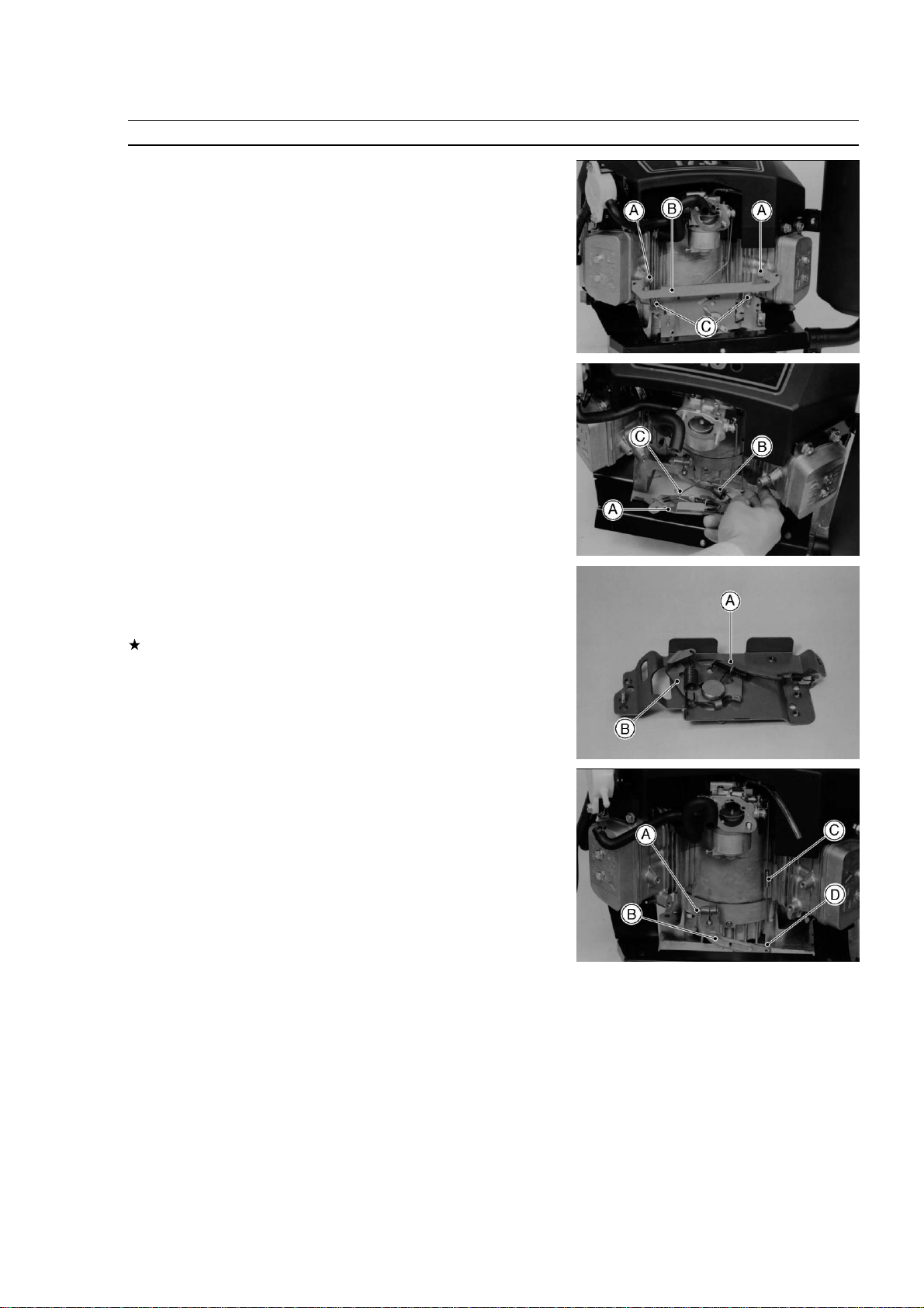
Control Panel Assembly Removal
•
Remove:
Air Cleaner (see Cleaner Body Removal)
Air Cleaner Mount Bracket Bolts [A]
Air Cleaner Mount Bracket [B]
Earth Lead (Starter Model)
Control Panel Mounting Bolts [C]
•
Remove the control panel assembly [A] while unhooking the governor
spring [B] end loop at the panel bracket.
•
Clear the choke link rod lower end [C] from the choke lever.
Control Panel Assembly Installation
•
Before installing the control panel assembly, check to see that the
choke lever [A] and engine speed control lever [B] move smoothly in
all directions.
If any part is worn or damaged, replace the control panel assembly.
•
After installation, adjust the low idle speeds and high idle speeds
to the specifications (see Low Idle Speed and High Idle Speed
adjustment).
Governor Arm Removal
•
Remove:
Control Panel Assembly
•
Loosen the clamp nut [A] and take off the governor arm [B].
•
Unhooking the throttle link rod spring [C] end loop and clear the
throttle link rod lower end [D].
2-10 FUEL SYSTEM
Governor Link Mechanism
Governor Arm Installation
•
Install the governor arm [A] onto the governor shaft [B] temporarily.
•
Be sure the link spring [C] around the throttle link rod [D] is inplace
and that it pulls the governor arm and throttle lever [E] each other.
•
Loosen the clamp nut [F] on the governor arm enough to move the
governor shaft.
•
Turn the top end of the governor arm counterclockwise to fully open
the carburetor [G] throttle valve and hold it there.
•
Turn the governor shaft counterclockwise, fully turn the shaft to end
of its travel.
•
Tighten the clamp nut.
Torque - Governor Arm Clamp Nut: 7.8 N
1
m (0.80 kg
1
m, 69 in
1
lb)
•
Be sure the governor shaft extend from the governor arm is approxi-
mately 7 mm (0.3 in) [H] as shown.
•
Install the control panel assembly, and connect the governor arm with
the governor spring.
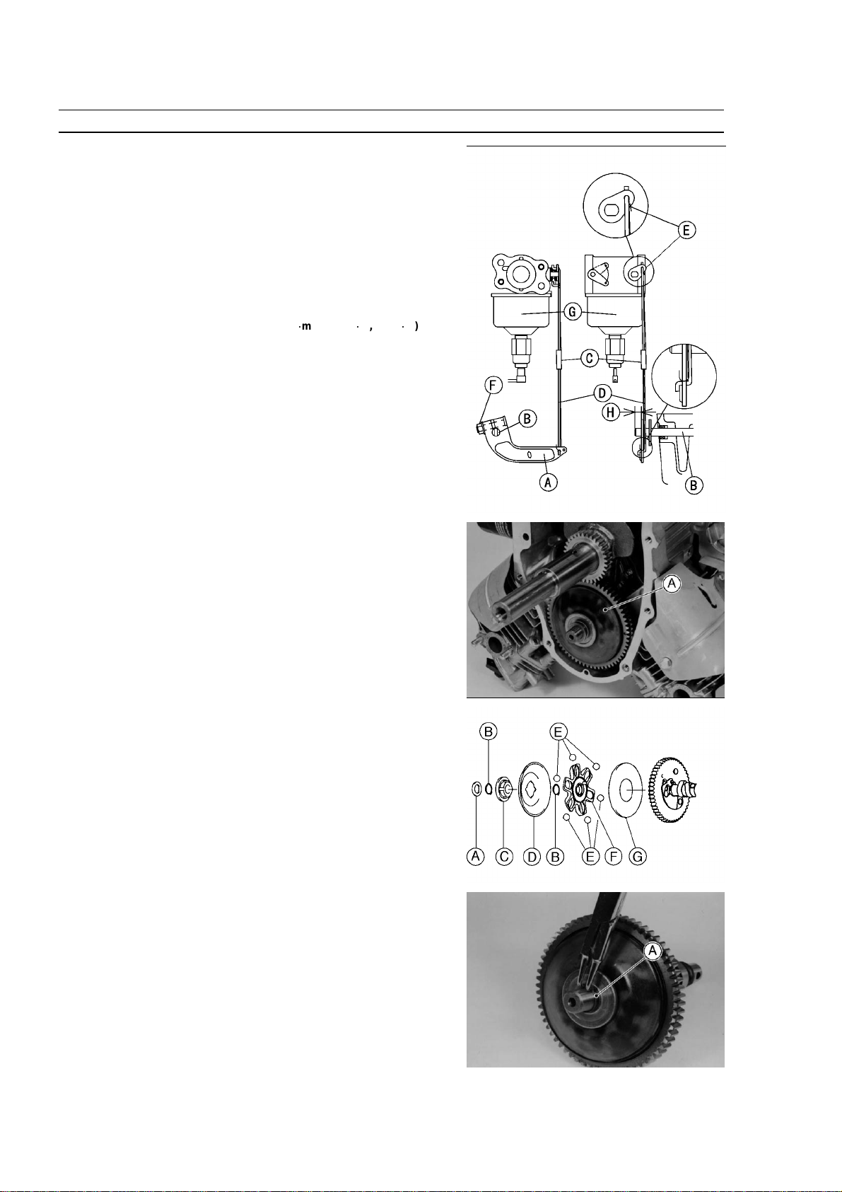
Governor Assembly Removal
•
Remove the crankcase cover (see Camshaft/Crankshaft chapter).
•
Remove the push rod. (see Engine Top End chapter)
•
Upside down the engine.
•
Remove the camshaft [A].
•
Remove:
Washer [A]
Snap Ring [B]
Sleeve [C]
Governor Plate [D]
Snap Ring [B]
Steel balls [E]
Ball Guide [F]
Ball Plate [G]
Governor Assembly Installation
•
Fit the snap rings [A] into the grooves securely.
•
Spin the governor plate by hand and check that the steel balls and
governor plate operate freely.
FUEL SYSTEM 2-11
Governor Link Mechanism
Governor Assembly Inspection
Visually check all governor parts for wear and damage.
If any parts are worm or damaged, replace them.
Governor Shaft Removal
•
Split the crankcase (see Camshaft/Crankcase chapter).
•
Unscrewthe governor shaft plate screws [A], and pull out the governor
shaft [B] outside.
NOTE
It is not necessary to remove the governor shaft unless it is being
replaced.
•
Replace the oil seal only if the lip shows signs of leakage or it has
been damaged.
•
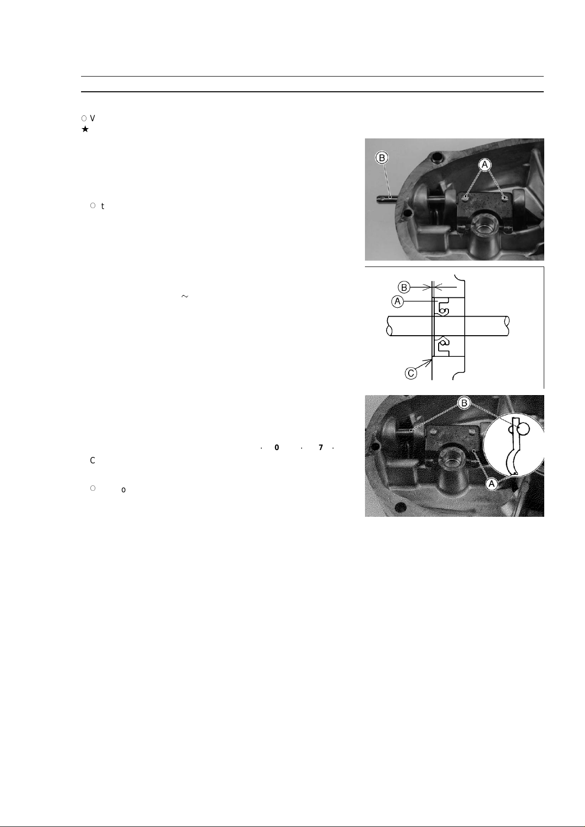
The oil seal [A] must be assembled with seal lip towards inside of the
engine.
•
Press in the oil seal 0
1.0 mm (0.04 in.) [B] flush or below the
crankcase surface [C].
Governor Shaft Installation
•
Apply engine oil to the governor shaft.
•
Insert the governor shaft into the crankcase.
•
Install the governor shaft plate [A] to the shaft [B] as shown.
Torque - Governor Shaft Plate Screws: 2.0 N
1
m (0.20 kg
1
m, 17 in
1
lb)
•
Check that the governor shaft moves freely in its operating range.
NOTE
If the oil seal is removed, oil seal is put on after shaft is installed.
2-12 FUEL SYSTEM
Carburetor
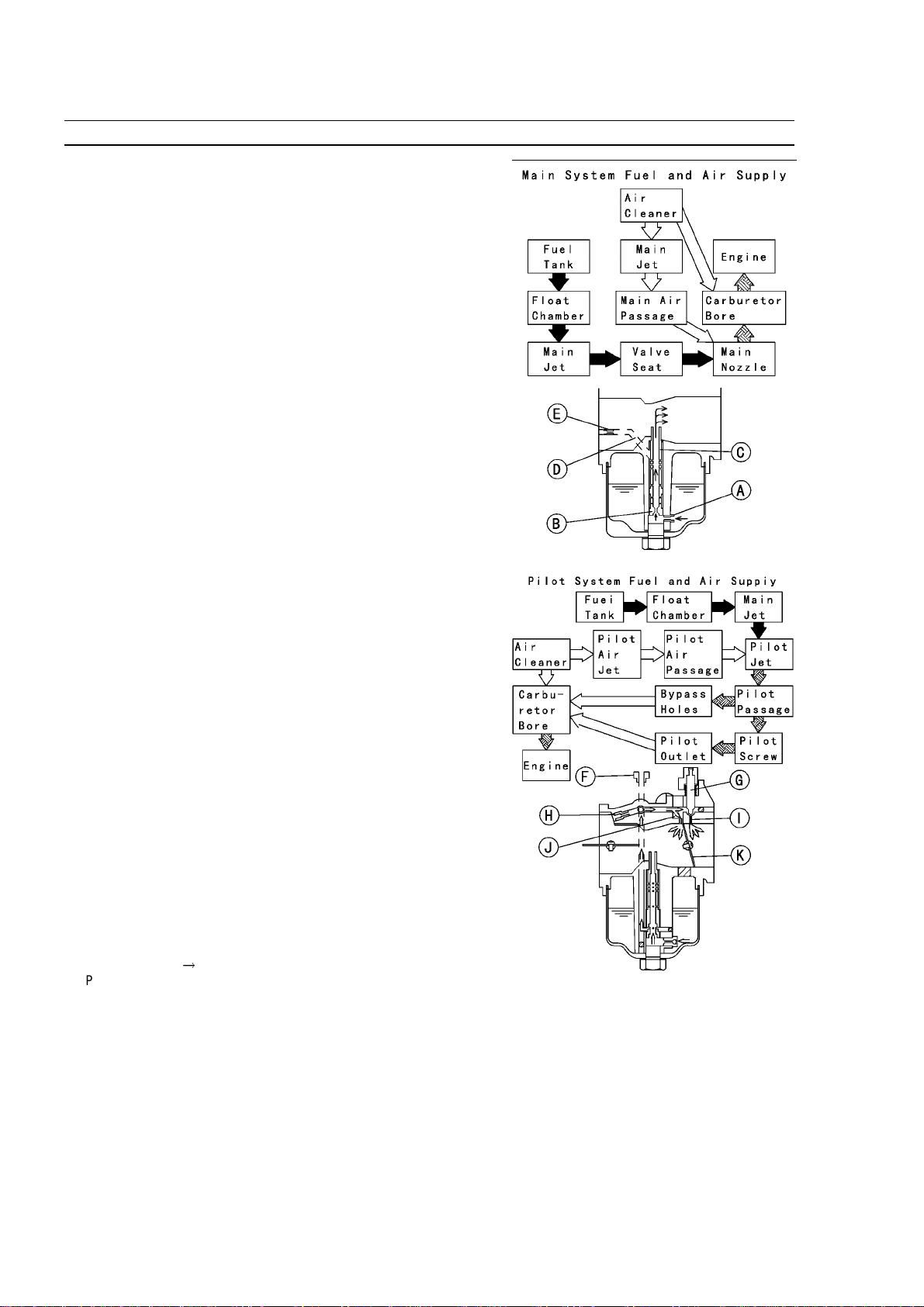
Fuel and Air Flow
The main system of the carburetor consists of the main jet [A], Valve
seat [B] main nozzle [C], and the main air passage [D] (main air jet
[E]). The main system meters fuel to the engine during moderate to
heavy load conditions. Fuel flows through the main jet and into the
main nozzle, where it is joined by air from the main air passage (main
air jet). The resulting mixture flows out the end of the main nozzle into
the carburetor bore, where it is atomized by the high speed air flow, and
carried into the engine.
The pilot system includes the pilot jet [F], pilot screw [G] (Idle mixture
screw), pilot air jet [H], pilot outlet [I], and the bypass holes [J]. The pilot
system meters the fuel/air mixture while the engine is idling and running
under a light load. Under these conditions there is very little air flow
through the carburetor bore; so little that it is not enough to draw fuel
through the main system of the carburetor and atomize it. Instead, the
fuel is drawn through the pilot system, since the nearly closed throttle
valve [K] causes high speed air flow past the pilot outlet and bypass
holes (even at low engine speed).
Fuel flow in the pilot system is metered by the pilot jet. Air for better
atomization is admitted via the pilot air jet in the mouthof the carburetor.
The fuel/air mixture passes into the bore of the carburetor side stream
of the throttle valve through the bypass holes and pilot outlet. While
the throttle valve is almost closed, it covers the small bypass holes
opening into the bore from the pilot system. As the throttle valve begins
to open, it uncovers the bypass holes, allowing more fuel/air mixture to
flow. The extra flow is needed because the engine starts to run faster
as the throttle is opened. The pilot screw controls the amount of fuel/air
mixture allowed through the pilot outlet, but does not meter the bypass
holes. A moderate amount of air comes in around the throttle valve at
an idle, so adjusting the pilot screw changes the fuel/air ratio. Turning
the pilot screw (Idle mixture screw) out (Counterclockwise) enrichens
the mixture; turning it in (clockwise) leans the mixture.
Main Fuel Flow
!
Pilot Fuel Flow ⇒
Loading...