


 Loading...
NINJA 650R
ER-6f ABS
ER-6f
Motorcycle
Service Manual

Quick Reference Guide
This quick reference guide will assist you in locating a desired topic or procedure.
•Bend the pages back to match the black tab of the desired chapter number with the black tab on the edge at each table of contents page.
•Refer to the sectional table of contents for the exact pages to locate the specific topic required.
General Information |
1 |
j |
|
|
|
Periodic Maintenance |
2 |
j |
|
|
|
Fuel System (DFI) |
3 |
j |
|
|
|
Cooling System |
4 |
j |
|
|
|
Engine Top End |
5 |
j |
|
|
|
Clutch |
6 |
j |
|
|
|
Engine Lubrication System |
7 |
j |
|
|
|
Engine Removal/Installation |
8 |
j |
|
|
|
Crankshaft/Transmission |
9 |
j |
|
|
|
Wheels/Tires |
10 |
j |
|
|
|
Final Drive |
11 |
j |
|
|
|
Brakes |
12 |
j |
|
|
|
Suspension |
13 |
j |
|
|
|
Steering |
14 |
j |
|
|
|
Frame |
15 |
j |
|
|
|
Electrical System |
16 |
j |
|
|
|
Appendix |
17 |
j |

NINJA 650R
ER-6f
ER-6f ABS
Motorcycle
Service Manual
All rights reserved. No parts of this publication may be reproduced, stored in a retrieval system, or transmitted in any form or by any means, electronic mechanical photocopying, recording or otherwise, without the prior written permission of Quality Division/Consumer Products & Machinery Company/Kawasaki Heavy Industries, Ltd., Japan.
No liability can be accepted for any inaccuracies or omissions in this publication, although every possible care has been taken to make it as complete and accurate as possible.
The right is reserved to make changes at any time without prior notice and without incurring an obligation to make such changes to products manufactured previously. See your Motorcycle dealer for the latest information on product improvements incorporated after this publication.
All information contained in this publication is based on the latest product information available at the time of publication. Illustrations and photographs in this publication are intended for reference use only and may not depict actual model component parts.
© 2005 Kawasaki Heavy Industries, Ltd. |
First Edition (1) : Nov. 2, 2005 (M) |

EMISSION CONTROL INFORMATION
To protect the environment in which we all live, Kawasaki has incorporated crankcase emission (1) and exhaust emission (2) control systems in compliance with applicable regulations of the United States Environmental Protection Agency and California Air Resources Board. Additionally, Kawasaki has incorporated an evaporative emission control system (3) in compliance with applicable regulations of the California Air Resources Board on vehicles sold in California only.
1. Crankcase Emission Control System
This system eliminates the release of crankcase vapors into the atmosphere. Instead, the vapors are routed through an oil separator to the inlet side of the engine. While the engine is operating, the vapors are drawn into combustion chamber, where they are burned along with the fuel and air supplied by the fuel injection system.
2. Exhaust Emission Control System
This system reduces the amount of pollutants discharged into the atmosphere by the exhaust of this motorcycle. The fuel, ignition, and exhaust systems of this motorcycle have been carefully designed and constructed to ensure an efficient engine with low exhaust pollutant levels.
The exhaust system of this model motorcycle manufactured primarily for sale in California includes a catalytic converter system.
3. Evaporative Emission Control System
Vapors caused by fuel evaporation in the fuel system are not vented into the atmosphere. Instead, fuel vapors are routed into the running engine to be burned, or stored in a canister when the engine is stopped. Liquid fuel is caught by a vapor separator and returned to the fuel tank.
The Clean Air Act, which is the Federal law covering motor vehicle pollution, contains what is commonly referred to as the Act’s “tampering provisions”.
“Sec. 203(a) The following acts and the causing thereof are prohibited.
(3)(A) for any person to remove or render inoperative any device or element of design installed on or in a motor vehicle or motor vehicle engine in compliance with regulations under this title prior to its sale and delivery to the ultimate purchaser, or for any manufacturer or dealer knowingly to remove or render inoperative any such device or element of design after such sale and delivery to the ultimate purchaser.
(3)(B) for any person engaged in the business of repairing, servicing, selling, leasing, or trading motor vehicles or motor vehicle engines, or who operates a fleet of motor vehicles knowingly to remove or render inoperative any device or element of design installed on or in a motor vehicle or motor vehicle engine in compliance with regulations under this title following its sale and delivery to the ultimate purchaser...”
NOTE
○The phrase “remove or render inoperative any device or element of design” has been generally interpreted as follows.
1.Tampering does not include the temporary removal or rendering inoperative of devices or elements of design in order to perform maintenance.
2.Tampering could include.
a.Maladjustment of vehicle components such that the emission standards are exceeded.
b.Use of replacement parts or accessories which adversely affect the performance or durability of the motorcycle.
c.Addition of components or accessories that result in the vehicle exceeding the standards.
d.Permanently removing, disconnecting, or rendering inoperative any component or element of design of the emission control systems.
WE RECOMMEND THAT ALL DEALERS OBSERVE THESE PROVISIONS OF FEDERAL LAW, THE VIOLATION OF WHICH IS PUNISHABLE BY CIVIL PENALTIES NOT EXCEEDING $10 000 PER VIOLATION.

TAMPERING WITH NOISE CONTROL SYSTEM PROHIBITED
Federal law prohibits the following acts or the causing thereof. (1) The removal or rendering inoperative by any person other than for purposes of maintenance, repair, or replacement, of any device or element of design incorporated into any new vehicle for the purpose of noise control prior to its sale or delivery to the ultimate purchaser or while it is in use, or (2) the use of the vehicle after such device or element of design has been removed or rendered inoperative by any person.
Among those acts presumed to constitute tampering are the acts listed below.
•Replacement of the original exhaust system or muffler with a component not in compliance with Federal regulations.
•Removal of the muffler(s) or any internal portion of the muffler(s).
•Removal of the air box or air box cover.
•Modifications to the muffler(s) or air inlet system by cutting, drilling, or other means if such modifications result in increased noise levels.
Foreword
This manual is designed primarily for use by trained mechanics in a properly equipped shop. However, it contains enough detail and basic information to make it useful to the owner who desires to perform his own basic maintenance and repair work. A basic knowledge of mechanics, the proper use of tools, and workshop procedures must be understood in order to carry out maintenance and repair satisfactorily. Whenever the owner has insufficient experience or doubts his ability to do the work, all adjustments, maintenance, and repair should be carried out only by qualified mechanics.
In order to perform the work efficiently and to avoid costly mistakes, read the text, thoroughly familiarize yourself with the procedures before starting work, and then do the work carefully in a clean area. Whenever special tools or equipment are specified, do not use makeshift tools or equipment. Precision measurements can only be made if the proper instruments are used, and the use of substitute tools may adversely affect safe operation.
For the duration of the warranty period, we recommend that all repairs and scheduled maintenance be performed in accordance with this service manual. Any owner maintenance or repair procedure not performed in accordance with this manual may void the warranty.
To get the longest life out of your vehicle.
•Follow the Periodic Maintenance Chart in the Service Manual.
•Be alert for problems and non-scheduled maintenance.
•Use proper tools and genuine Kawasaki Motorcycle parts. Special tools, gauges, and testers that are necessary when servicing Kawasaki motorcycles are introduced by the Service Manual. Genuine parts provided as spare parts are listed in the Parts Catalog.
•Follow the procedures in this manual carefully. Don’t take shortcuts.
•Remember to keep complete records of maintenance and repair with dates and any new parts installed.
How to Use This Manual
In this manual, the product is divided into its major systems and these systems make up the manual’s chapters. The Quick Reference
Guide shows you all of the product’s system and assists in locating their chapters. Each chapter in turn has its own comprehensive Table of Contents.
For example, if you want ignition coil information, use the Quick Reference Guide to locate the Electrical System chapter. Then, use the Table of Contents on the first page of the chapter to find the Ignition Coil section.
Whenever you see these WARNING and CAUTION symbols, heed their instructions! Always follow safe operating and maintenance practices.

 WARNING
This warning symbol identifies special instructions or procedures which, if not correctly followed, could result in personal injury, or loss of life.
CAUTION
This caution symbol identifies special instructions or procedures which, if not strictly observed, could result in damage to or destruction of equipment.
This manual contains four more symbols (in addition to WARNING and CAUTION) which will help you distinguish different types of information.
NOTE
○This note symbol indicates points of particular interest for more efficient and convenient operation.
•Indicatesdone. a procedural step or work to be ○Indicates a procedural sub-step or how to do the work of the procedural step it follows. It
also precedes the text of a NOTE.
 Indicates a conditional step or what action to take based on the results of the test or inspection in the procedural step or sub-step it follows.
In most chapters an exploded view illustration of the system components follows the Table of Contents. In these illustrations you will find the instructions indicating which parts require specified tightening torque, oil, grease or a locking agent during assembly.
LIST OF ABBREVIATIONS
A |
ampere(s) |
lb |
pound(s) |
ABDC |
after bottom dead center |
m |
meter(s) |
AC |
alternating current |
min |
minute(s) |
ATDC |
after top dead center |
N |
newton(s) |
BBDC |
before bottom dead center |
Pa |
pascal(s) |
BDC |
bottom dead center |
PS |
horsepower |
BTDC |
before top dead center |
psi |
pound(s) per square inch |
°C |
degree(s) Celsius |
r |
revolution |
DC |
direct current |
rpm |
revolution(s) per minute |
F |
farad(s) |
TDC |
top dead center |
°F |
degree(s) Fahrenheit |
TIR |
total indicator reading |
ft |
foot, feet |
V |
volt(s) |
g |
gram(s) |
W |
watt(s) |
h |
hour(s) |
Ω |
ohm(s) |
L |
liter(s) |
|
|
COUNTRY AND AREA CODES
AT |
Austria |
DE |
Germany |
CA |
Canada |
GB |
United Kingdom |
CAL |
California |
US |
United States |
CH |
Switzerland |
WVTA |
Whole Vehicle Type Approval |
GENERAL INFORMATION 1-1
General Information |
|
|
|
Table of Contents |
|
|
|
|
1 |
|
|
Before Servicing |
1-2 |
|
|
|
|
||
Model Identification................................................................................................................. |
1-7 |
|
|
General Specifications............................................................................................................ |
1-10 |
|
|
Technical Information - Cassette Type Transmission ............................................................. |
1-13 |
|
|
Technical Information - Inlet Air Pressure Sensor ................................................................. |
1-14 |
|
|
Technical Information – ABS (Anti – Lock Brake System)...................................................... |
1-15 |
|
|
Unit Conversion Table ............................................................................................................ |
1-27 |
|
|

1-2 GENERAL INFORMATION
Before Servicing
Before starting to perform an inspection service or carry out a disassembly and reassembly operation on a motorcycle, read the precautions given below. To facilitate actual operations, notes, illustrations, photographs, cautions, and detailed descriptions have been included in each chapter wherever necessary. This section explains the items that require particular attention during the removal and reinstallation or disassembly and reassembly of general parts.
Especially note the following:
Battery Ground
Before completing any service on the motorcycle, disconnect the battery cables from the battery to prevent the engine from accidentally turning over. Disconnect the ground cable (–) first and then the positive (+). When completed with the service, first connect the positive (+) cable to the positive (+) terminal of the battery then the negative (–) cable to the negative terminal.
Edges of Parts
Lift large or heavy parts wearing gloves to prevent injury from possible sharp edges on the parts.
Solvent
Use a high-flush point solvent when cleaning parts. High -flush point solvent should be used according to directions of the solvent manufacturer.
Cleaning Vehicle before Disassembly
Clean the vehicle thoroughly before disassembly. Dirt or other foreign materials entering into sealed areas during vehicle disassembly can cause excessive wear and decrease performance of the vehicle.
GENERAL INFORMATION 1-3
Before Servicing
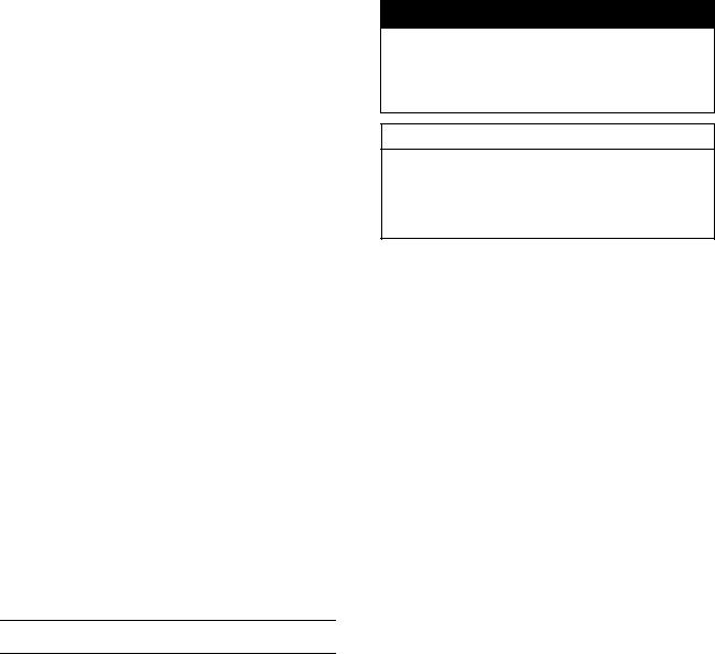
Arrangement and Cleaning of Removed Parts
Disassembled parts are easy to confuse. Arrange the parts according to the order the parts were disassembled and clean the parts in order prior to assembly.
Storage of Removed Parts
After all the parts including subassembly parts have been cleaned, store the parts in a clean area. Put a clean cloth or plastic sheet over the parts to protect from any foreign materials that may collect before re-assembly.
Inspection
Reuse of worn or damaged parts may lead to serious accident. Visually inspect removed parts for corrosion, discoloration, or other damage. Refer to the appropriate sections of this manual for service limits on individual parts. Replace the parts if any damage has been found or if the part is beyond its service limit.
Replacement Parts
Replacement parts must be KAWASAKI genuine or recommended by KAWASAKI. Gaskets, O-rings, oil seals, grease seals, circlips or cotter pins must be replaced with new ones whenever disassembled.
Assembly Order
In most cases assembly order is the reverse of disassembly, however, if assembly order is provided in this Service Manual, follow the procedures given.
1-4 GENERAL INFORMATION
Before Servicing
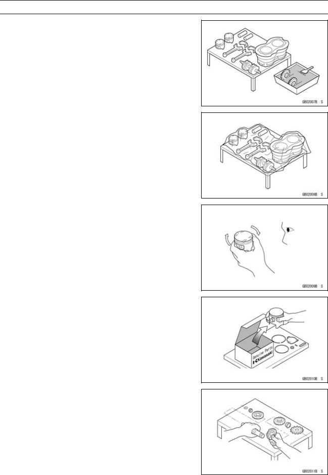
Tightening Sequence
Generally, when installing a part with several bolts, nuts, or screws, start them all in their holes and tighten them to a snug fit. Then tighten them according to the specified sequence to prevent case warpage or deformation which can lead to malfunction. Conversely when loosening the bolts, nuts, or screws, first loosen all of them by about a quarter turn and then remove them. If the specified tightening sequence is not indicated, tighten the fasteners alternating diagonally.
Tightening Torque
Incorrect torque applied to a bolt, nut, or screw may lead to serious damage. Tighten fasteners to the specified torque using a good quality torque wrench. Often, the tightening sequence is followed twice-initial tightening and final tightening with torque wrench.
Force
Use common sense during disassembly and assembly, excessive force can cause expensive or hard to repair damage. When necessary, remove screws that have a non -permanent locking agent applied using an impact driver. Use a plastic-faced mallet whenever tapping is necessary.
Gasket, O-ring
Hardening, shrinkage, or damage of both gaskets and O-rings after disassembly can reduce sealing performance. Remove old gaskets and clean the sealing surfaces thoroughly so that no gasket material or other material remains. Install new gaskets and replace used O-rings when re-assembling
Liquid Gasket, Non-permanent Locking Agent
For applications that require Liquid Gasket or a Non-permanent Locking Agent, clean the surfaces so that no oil residue remains before applying liquid gasket or non-permanent locking agent. Do not apply them excessively. Excessive application can clog oil passages and cause serious damage.

GENERAL INFORMATION 1-5
Before Servicing
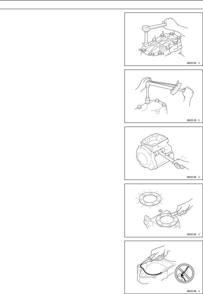
Press
For items such as bearings or oil seals that must be pressed into place, apply small amount of oil to the contact area. Be sure to maintain proper alignment and use smooth movements when installing.
Ball Bearing and Needle Bearing
Do not remove pressed ball or needle unless removal is absolutely necessary. Replace with new ones whenever removed. Press bearings with the manufacturer and size marks facing out. Press the bearing into place by putting pressure on the correct bearing race as shown.
Pressing the incorrect race can cause pressure between the inner and outer race and result in bearing damage.
Oil Seal, Grease Seal
Do not remove pressed oil or grease seals unless removal is necessary. Replace with new ones whenever removed. Press new oil seals with manufacture and size marks facing out. Make sure the seal is aligned properly when installing.
Apply specified grease to the lip of seal before installing the seal.
Circlips, Cotter Pins
Replace circlips or cotter pins that were removed with new ones. Take care not to open the clip excessively when installing to prevent deformation.
1-6 GENERAL INFORMATION
Before Servicing
Lubrication
It is important to lubricate rotating or sliding parts during assembly to minimize wear during initial operation. Lubrication points are called out throughout this manual, apply the specific oil or grease as specified.
Direction of Engine Rotation
When rotating the crankshaft by hand, the free play amount of rotating direction will affect the adjustment. Rotate the crankshaft to positive direction (clockwise viewed from output side).
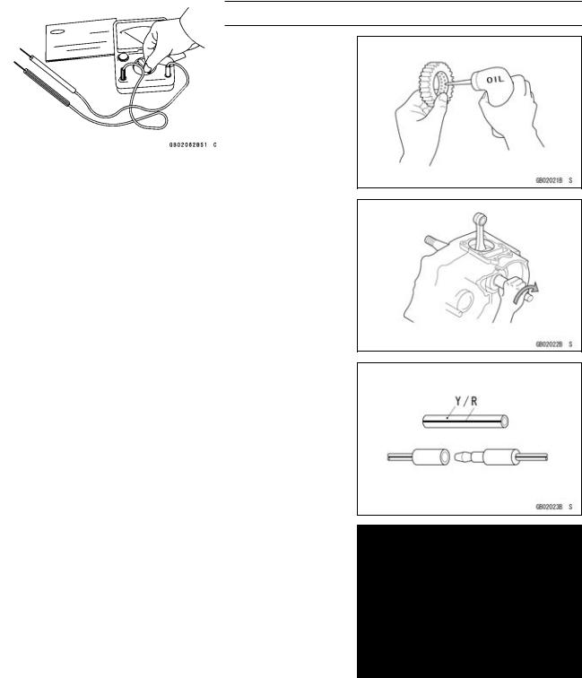
Electrical Wires
A two-color wire is identified first by the primary color and then the stripe color. Unless instructed otherwise, electrical wires must be connected to those of the same color.
Instrument
Use a meter that has enough accuracy for an accurate measurement. Read the manufacture’s instructions thoroughly before using the meter. Incorrect values may lead to improper adjustments.
GENERAL INFORMATION 1-7
Model Identification
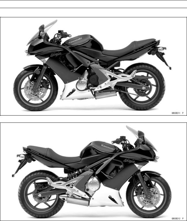
EX650A6F (United States and Canada) Left Side View
EX650A6F (United States and Canada) Right Side View
1-8 GENERAL INFORMATION
Model Identification
EX650A6F (Europe) Left Side View
EX650A6F (Europe) Right Side View
 User Manual")
GENERAL INFORMATION 1-9
Model Identification
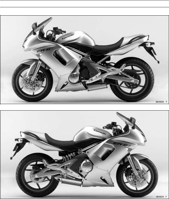
EX650B6F Left Side View
EX650B6F Right Side View
Frame Number |
|
Engine Number |
|
|
|
|
|
|

1-10 GENERAL INFORMATION
General Specifications
Items |
EX650A6F, EX650B6F |
Dimensions |
|
Overall Length |
2 105 mm (82.9 in.) |
Overall Width |
760 mm (29.9 in.) |
Overall Height |
1 210 mm (47.6 in.) |
Wheelbase |
1 410 mm (55.5 in.) |
Road Clearance |
145 mm (5.7 in.) |
Seat Height |
790 mm (31.1 in.) |
Dry Mass: |
|
EX650A6F |
178 kg (392.5 lb) |
|
(CAL) 178.5 kg (393.6 lb) |
EX650B6F |
182 kg (401.3 lb) |
Curb Mass: |
|
Front: |
|
EX650A6F |
101 kg (222.7 lb) |
EX650B6F |
103 kg (227.1 lb) |
Rear: |
|
EX650A6F |
99 kg (216.1 lb) |
|
(CAL) 99.5 kg (219.4 lb) |
EX650B6F |
101 kg (222.7 lb) |
Fuel Tank Capacity |
15.5 L (4.1 US gal.) |
Performance |
|
Minimum Turning Radius |
2.7 m (8.9 ft) |
Engine |
|
Type |
4-stroke, DOHC, 2-cylinder |
Cooling System |
Liquid-cooled |
Bore and Stroke |
83 × 60 mm (3.3 × 2.4 in.) |
Displacement |
649 cm³ (39.60 cu in.) |
Compression Ratio |
11.3 : 1 |
Maximum Horsepower |
53 kW (72 PS) @8 500 r/min (rpm), |
Maximum Torque |
66 N·m (6.7 kgf·m, 49 ft·lb) @7 000 r/min (rpm), |
Carburetion System |
FI (Fuel Injection) KEIHIN TTK38 × 2 |
Starting System |
Electric starter |
Ignition System |
Battery and coil (transistorized) |
Timing Advance |
Electronically advanced (digital igniter) |
Ignition Timing |
From 10° BTDC @1 300 r/min (rpm) to 35° BTDC @4 800 |
|
r/min (rpm) |
Spark Plug |
NGK CR9EIA-9 |
Cylinder Numbering Method |
Left to right, 1-2 |
Firing Order |
1-2 |
Valve Timing: |
|
Inlet: |
|
Open |
31° BTDC |
Close |
61° ABDC |
Duration |
272° |
|
|
GENERAL INFORMATION 1-11 |
General Specifications |
|
|
|
|
|
|
|
|
Items |
EX650A6F, EX650B6F |
|
Exhaust: |
|
|
Open |
50° BBDC |
|
Close |
30° ATDC |
|
Duration |
|
|
|
260° |
|
Lubrication System |
|
Forced lubrication (semi-dry sump) |
Engine Oil: |
|
|
Type |
|
API SE, SF or SG |
|
|
API SH, SJ or SL with JASO MA |
Viscosity |
|
SAE 10W-40 |
Capacity |
2.4 L (2.5 US qt) |
|
Drive Train |
|
|
Primary Reduction System: |
|
|
Type |
|
Gear |
Reduction Ratio |
|
2.095 (88/42) |
Clutch Type |
|
Wet multi disc |
Transmission: |
|
|
Type |
|
6-speed, constant mesh, return shift |
Gear Ratios: |
|
|
1st |
|
2.438 (39/16) |
2nd |
|
1.714 (36/21) |
3rd |
|
1.333 (32/24) |
4th |
|
1.111 (30/27) |
5th |
|
0.966 (28/29) |
6th |
|
0.852 (23/27) |
Final Drive System: |
|
|
Type |
|
Chain drive |
Reduction Ratio |
|
3.067 (46/15) |
Overall Drive Ratio |
5.473 @Top gear |
|
Frame |
|
|
Type |
Tubular, diamond |
|
Caster (Rake Angle) |
25° |
|
Trail |
106 mm (4.2 in.) |
|
Front Tire: |
|
|
Type |
Tubeless |
|
Size |
120/70 ZR17 M/C (58W) |
|
Rim Size |
17 × 3.50 |
|
Rear Tire: |
|
|
Type |
Tubeless |
|
Size |
160/60 ZR17 M/C (69W) |
|
Rim Size |
|
17 × 4.50 |
Front Suspension: |
|
|
Type |
|
Telescopic fork |
Wheel Travel |
|
120 mm (4.7 in.) |
Rear Suspension: |
|
|

1-12 GENERAL INFORMATION
General Specifications
Items |
|
EX650A6F, EX650B6F |
Type |
Swingarm |
|
Wheel Travel |
125 mm (4.9 in.) |
|
Brake Type: |
|
|
Front |
Dual discs |
|
Rear |
Single disc |
|
Electrical Equipment |
|
|
Battery |
12 |
V 10 Ah |
Headlight: |
|
|
Type |
Semi-sealed beam |
|
Bulb |
12 |
V 55 W × 2/55 W (Hi/Lo) |
Tail/Brake Light |
12 |
V 5/21 W |
Alternator: |
|
|
Type |
Three-phase AC |
|
Rated Output |
24 |
A/14 V @5 000 r/min (rpm) |
Specifications are subject to change without notice, and may not apply to every country.
GENERAL INFORMATION 1-13
Technical Information - Cassette Type Transmission
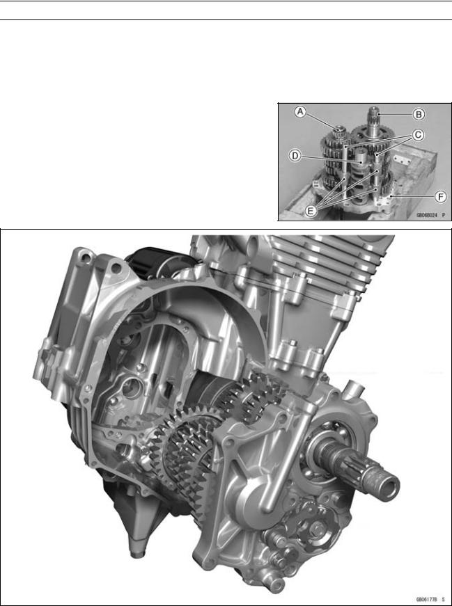
Cassette Type Transmission
The transmission of the current model is unable to be removed without disassembling upper and lower crankcase halves.
The EX650A/B enables transmission to be removed from the right side of engine as an assy, without disassembling crankcase halves (see Transmission Assy Removal in the Crankshaft/Transmission chapter).
Transmission Assy: Drive Shaft [A] Output Shaft [B] Shift Rods [C] Shift Dram [D] Shift Forks [E]
Transmission Case [F]
1-14 GENERAL INFORMATION
Technical Information - Inlet Air Pressure Sensor
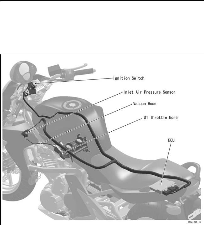
Atmospheric pressure sensor and camshaft position sensor are not equipped with the EX650A/B. As a substitute of these sensors above, the EX650A/B recognizes atmospheric pressure and intake stroke of #1 by the signal of inlet air pressure sensor.
The ECU detects atmospheric pressure when the ignition is switched ON. While the engine is running, the ECU also presumes atmospheric pressure by analyzing the waveform of boost pressure over fixed period. The intake stroke is recognized by waveform of boost pressure, therefore the system can recognize the difference of each stroke.
GENERAL INFORMATION 1-15
Technical Information – ABS (Anti – Lock Brake System)
Outline
ABS controls the brake caliper fluid pressure by means of mechatronics - a combination of electronic and hydraulic control technology in order to keep the friction force between the tires and the road surfaces close to the maximum value and prevent wheel lock. But it does not operate during cruising.
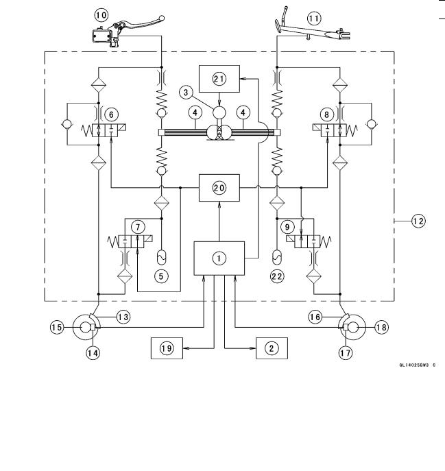
ABS Total System
|
|
|
|
|
|
|
|
|
|
1. |
ECU |
13. |
Front Brake Caliper |
|
2. |
ABS Indicator Light (LED) |
14. |
Front Wheel Rotation Sensor |
|
3. |
Pump Motor |
15. |
Front Wheel Rotation Sensor Rotor |
|
4. |
Pump |
16. |
Rear Brake Caliper |
|
5. |
Front Reservoir |
17. |
Rear Wheel Rotation Sensor |
|
6. |
Front Inlet Solenoid Valve |
18. |
Rear Wheel Rotation Sensor Rotor |
|
7. |
Front Outlet Solenoid Valve |
19. |
ABS Kawasaki Self-diagnosis System Con- |
|
8. |
Rear Inlet Solenoid Valve |
|
nector |
|
9. |
Rear Outlet Solenoid Valve |
20. |
ABS Solenoid Valve Relay |
|
10. |
Brake Lever |
21. |
ABS Motor Relay |
|
11. |
Brake Pedal |
22. |
Rear Reservoir |
|
12. |
ABS Hydraulic Unit |
|
|
|
1-16 GENERAL INFORMATION
Technical Information – ABS (Anti – Lock Brake System)
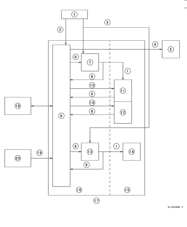
ABS System Block Diagram
|
|
|
|
|
|
1. |
Power Source |
12. |
Inlet Solenoid Valve |
||
2. |
Ignition Power Source |
13. |
ABS Motor Relay |
||
3. Battery Power Source |
14. |
Pump Motor |
|||
4. |
Indicator Light Output |
15. |
Hydraulic Unit |
||
5. |
ABS Indicator Light (LED) |
16. |
ABS Controller |
||
6. |
ECU |
17. |
ABS Hydraulic Unit |
||
7. |
ABS Solenoid Valve Relay |
18. |
ABS Kawasaki Self-diagnosis System Con- |
||
8. |
Output |
|
nector |
||
9. |
Monitor Input |
19. |
Wheel Rotation Input |
||
10. |
Valve Output |
20. |
Wheel Rotation Sensor |
||
11. |
Outlet Solenoid Valve |
|
|
|
|
GENERAL INFORMATION 1-17
Technical Information – ABS (Anti – Lock Brake System)
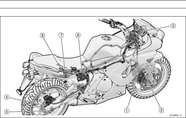
Related Parts and Function
1.Front Wheel Rotation Sensor
2.Front Wheel Rotation Sensor Rotor
3.Rear Wheel Rotation Sensor
4.Rear Wheel Rotation Sensor Rotor
5.ABS Indicator Light (LED)
6.ABS Hydraulic Unit
7.ABS Fuse Box
8.ABS Kawasaki Self-diagnosis System Connector
Wheel Rotation Sensor
The wheel rotation sensors output the rotation speed of each wheel to the ECU in the ABS hydraulic unit. The wheel rotation sensor is installed to the front fork and rear caliper bracket, and the sensor rotor is pressed into the brake disc. The number of teeth on the front and rear sensor rotor is 50.
ABS Indicator Light (LED)
The condition or the failure of the ABS system is indicated by various patterns of the ABS indicator light (LED) blinking.

1-18 GENERAL INFORMATION
Technical Information – ABS (Anti – Lock Brake System)
ABS Hydraulic Unit
The outlet and inlet solenoid valves, reservoir, pump motor, solenoid valve relay, motor relay, and ECU are built in the ABS hydraulic unit.
1.Brake Lever
2.Brake Pedal
3.Pump Motor
4.Rear Inlet Solenoid Valve
5.Rear Outlet Solenoid Valve
6.Rear Reservoir
7.Rear Caliper
8.Front Inlet Solenoid Valve
9.Front Outlet Solenoid Valve
10.Front Caliper
11.Front Reservoir
12.Orifice
13.Filter
14.Check Valve
GENERAL INFORMATION 1-19
Technical Information – ABS (Anti – Lock Brake System)
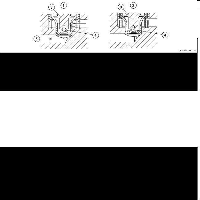
Inlet Solenoid Valve
Inlet solenoid valves control the brake pressure of each wheel by combining the operation of the outlet solenoid valve. The ECU changes the electric current in the solenoids of the inlet solenoid valve (2 way, 2 position electromagnetic valve) to move the tappet and change the fluid pressure to “Increase Mode”, “Hold Mode”, or “Decrease Mode”.
1.Increase Mode
2.Hold and Decrease Mode
3.Tappet
4.Valve Body
5.From Master Cylinder
Outlet Solenoid Valve
Outlet solenoid valves control the brake pressure of each wheel by combining the operation of the inlet solenoid valve. The ECU changes the electric current in the solenoids of the outlet solenoid valve (2 way, 2 position electromagnetic valve) to move the armature and change the fluid pressure to “Increase Mode”, “Hold Mode”, or “Decrease Mode”.
1.Decrease Mode
2.Increase and Hold Mode
3.Armature
4.Valve
5.To Reservoir
1-20 GENERAL INFORMATION
Technical Information – ABS (Anti – Lock Brake System)
Reservoir
When the passage opens between the caliper and the reservoir with the outlet solenoid valve in “Decrease Mode”, the brake fluid flows into the reservoir by pushing the piston, stays there temporarily, and then returns to the master cylinder. With the outlet solenoid valve “Increase or Hold Mode”, the pump returns the remaining brake fluid in the reservoir to the master cylinder.
1.From Outlet Solenoid Valve
2.To Pump
Pump Motor
The pump motor operates the pump, supply or return the brake fluid from the pump.
Pump
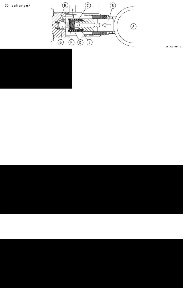
The pump operates continuously when the ABS is activated. The pump is driven by the motor and supply the brake fluid to the caliper or return the brake fluid in the reservoir to the master cylinder. The piston is reciprocated by the eccentric cam [A] on the end of the motor shaft and the pump sucks in or discharge the brake fluid.
When the pump pulls fluid in, the piston [B] is moved right by the force of the spring [C]. At this time, the spring [D] is compressed by the pressure of the brake fluid in the reservoir to open the inlet valve [E] and the brake fluid flows into the cylinder [F]. The outlet valve [G] is held closed by the force of the spring [H].
When the pump discharges the brake fluid, the inlet valve [E] is closed by the spring [D], and the piston [B] is moved left by the cam [A], producing pressure in the cylinder [F]. The pressure pushes the spring [H], opens the outlet valve [G], and the brake fluid returns to the master cylinder.
Spring [C]
Loading...