


 Kawasaki
Motorcycle
Motocyclette
Motorrad
Ninja 250R
ЕХ250К
 Kawasaki
KAWASAKI HEAVY INDUSTRIES,LTD. |
Printed in Thailand |
Consumer Products & Machinery Company |
|
Part No. 99976-1417 |
|
ENGLISH
Motorcycle
Owner's Manual

Whenever you see the symbols shown below, heed their instructions! Always follow safe operating and main tenance practices.
This warning symbol identifies special instructions or proce dures which, if not correctly fol lowed, could result in personal injury, or loss of life.
CAUTION
This caution symbol identifies special instructions or proce dures which, if not strictly ob served, could result in damage to or destruction of equipment.
NOTE
О This note symbol indicates points of particular interest for more efficient and convenient operation.
NOTICE
THIS PRODUCT HAS BEEN MANUFACTURED FOR USE IN A REASONABLE AND PRUDENT MANNER BY A QUALIFIED OP ERATOR AND AS A VEHICLE ONLY.
(Australian model only)
TAMPERING WITH NOISE CONTROL SYSTEM
PROHIBITED
Owners are warned that the law may prohibit:
(a)The removal or rendering inoperative by any person other than for purposes of maintenance, repair or replacement, of any device or element of design incorporated into any new vehicle for the purpose of noise control prior to its sale or delivery to the ultimate purchaser or while it is in use; and
(b)the use of the vehicle after such device or element of design has been removed or rendered inoperative by any person.
FOREWORD
Congratulations on your purchase of a new Kawasaki motorcycle. Your new motorcycle is the product of Kawasaki's advanced engineering, exhaustive testing, and continuous striving for superior reliability, safety and performance.
Please read this Owner's Manual carefully before riding so that you will be thoroughly familiar with the proper operation of your motorcycle's controls, its features, capabilities, and limitations. This manual offers many safe riding tips, but its purpose is not to provide instruction in all the techniques and skills required to ride a motorcycle safely. Kawasaki strongly recommends that all operators of this vehicle enroll in a motorcycle rider training program to attain awareness of the mental and physical requirements necessary for safe motorcycle operation.
To ensure a long, trouble-free life for your motorcycle, give it the proper care and maintenance described in this manual. For those who would like more detailed information on their Kawasaki Motorcycle, a Service Manual is available for purchase from any authorized Kawasaki motorcycle dealer. The Service Manual contains detailed disassembly and maintenance information. Those who plan to do their own work should, of course, be competent mechanics and possess the special tools described in the Service Manual.
Keep this Owner's Manual aboard your motorcycle at all times so that you can refer to it whenever you need information.
This manual should be considered a permanent part of the motorcycle and should remain with the motorcycle when it is sold.
All rights reserved. No part of this publication may be reproduced without our prior written permission.
This publication includes the latest information available at the time of printing. However, there may be minor differences between the actual product and illustrations and text in this manual.
All products are subject to change without prior notice or obligation.
KAWASAKI HEAVY INDUSTRIES, LTD.
Consumer Products & Machinery Company
©2008 Kawasaki Heavy Industries, Ltd. |
Jan. 2008. (1). (CR, CR, Ke) |
TABLE OF CONTENTS
SPECIFICATIONS |
10 |
Stand |
31 |
LOCATION OF PARTS |
14 |
Seats |
32 |
LOADING INFORMATION |
17 |
Helmet Hooks |
35 |
GENERAL INFORMATION |
20 |
Tool Kit |
36 |
Meter Instruments |
20 |
Tying Hooks |
37 |
Speedometer and Tachometer |
21 |
BREAK-IN |
38 |
Coolant Temperature Gauge |
21 |
HOW TO RIDE THE MOTORCYCLE . |
40 |
Warning/Indicator Lights |
21 |
Starting the Engine |
40 |
Key |
23 |
Jump Starting |
42 |
Ignition Switch/Steering Lock |
23 |
Moving Off |
44 |
Right Handlebar Switches |
25 |
Shifting Gears |
45 |
Engine Stop Switch: |
25 |
Braking |
46 |
Starter Button: |
26 |
Stopping the Engine |
48 |
Left Handlebar Switches |
26 |
Stopping the Motorcycle in an |
|
Dimmer Switch: |
26 |
Emergency |
48 |
Turn Signal Switch: |
27 |
Parking |
49 |
Horn Button: |
27 |
Catalytic Converter |
51 |
Fuel Tank Cap |
28 |
SAFE OPERATION |
53 |
Fuel Tank |
29 |
Safe Riding Technique |
53 |
Fuel Requirement: |
30 |
Daily Safety Checks |
55 |
Additional Considerations for High |
|
Speed Operation |
57 |
MAINTENANCE AND ADJUSTMENT |
59 |
Periodic Maintenance Chart |
60 |
Engine Oil |
69 |
Cooling System |
75 |
Spark Plugs |
81 |
Kawasaki Clean Air System |
82 |
Valve Clearance |
83 |
Air Cleaner |
83 |
Throttle Control System |
87 |
Engine Vacuum Synchronization |
90 |
Idle Speed |
91 |
Clutch |
92 |
Drive Chain |
94 |
Brakes |
102 |
Brake Light Switches |
107 |
Front Fork |
109 |
Rear Shock Absorbers |
110 |
Wheels |
111 |
Battery |
117 |
Headlight Beam |
123 |
Fuses |
125 |
Cleaning Your Motorcycle |
126 |
STORAGE... |
132 |
ENVIRONMENTAL PROTECTION |
135 |
LOCATION OF LABELS |
136 |
LABEL INFORMATION |
138 |
10 SPECIFICATIONS
|
SPECIFICATIONS |
PERFORMANCE |
|
Maximum Horsepower |
24 kW (33 PS) @11 000 r/min (rpm) |
Maximum Torque |
22.0 N-m (2.2 kgf-m, 16.2 ft-lb) @8 200 r/min (rpm) |
Minimum Turning Radius |
2.7 m (106.3 in.) |
DIMENSIONS |
|
Overall Length |
2 085 mm (82.09 in.) |
Overall Width |
715 mm (28.15 in.) |
Overall Height |
1 115 mm (43.90 in.) |
Wheelbase |
1 400 mm (55.12 in.) |
Road Clearance |
130 mm (5.19 in.) |
Dry Weight |
152 kg (335 lb) |
Curb Mass |
169 kg (373 lb) |
ENGINE |
|
Type |
DOHC, 2-cylinder, 4-stroke, liquid-cooled |
Displacement |
249 cm3 (15.2 cu in.) |
|
|
SPECIFICATIONS 11 |
Bore x Stroke |
|
62.0 x 41.2 mm (2.44 * 1.62 in.) |
Compression Ratio |
|
11.6:1 |
Starting System |
|
Electric starter |
Cylinder Numbering Method |
Left to right, 1-2 |
|
Firing Order |
|
1-2 |
Carburetion System |
|
Fl (Fuel Injection) |
Ignition System |
|
Battery and coil (transistorized ignition) |
Ignition Timing |
|
10° BTDC @1 300 r/min (rpm) ~ |
(Electronically advanced) |
|
38° BTDC @6 000 r/min (rpm) |
Spark Plugs |
|
NGK CR8E |
Lubrication System |
|
Forced lubrication (wet sump) |
Engine Oil |
Type : |
API SE, SF or SG |
|
|
API SH, SJ or SL with JASO MA |
|
|
SAE 10W-40 |
|
Capacity: 1.7 L (1.8 US qt) |
|
Coolant Capacity |
|
1.5 L (1.6 US qt) |

12 SPECIFICATIONS |
|
|
TRANSMISSION |
|
|
Transmission Type |
|
6-speed, return shift |
Clutch Type |
|
Wet, multi disc |
Driving System |
|
Chain drive |
Primary Reduction Ratio |
|
3.087 (71/23) |
Final Reduction Ratio |
|
3.071 (43/14) |
Overall Drive Ratio |
|
8.466 (Top gear) |
Gear Ratio |
1st |
2.600 (39/15) |
|
2nd |
1.789(34/19) |
|
3rd |
1.409(31/22) |
|
4th |
1.160(29/25) |
|
5th |
1.000(27/27) |
|
6th |
0.893 (25/28) |
FRAME |
|
|
Castor |
|
26° |
Trail |
|
82 mm (3.2 in.) |
Tire Size: |
Front |
110/70-17M/C(54S) |
SPECIFICATIONS 13
|
Rear |
130/70-17M/C(62S) |
Rim Size: |
Front |
17 x 2.75 |
|
Rear |
17 x 3.50 |
Fuel Tank Capacity |
|
17.8 L (4.7 US gal) |
ELECTRICAL EQUIPMENT |
|
|
Battery |
|
12 V 8 Ah |
Headlight |
|
High beam 12 V 55 Wx 2 |
|
|
Low beam 12 V 55 W |
Tail/Brake Light |
|
12 V 5/21 W |
CAUTION
The tail light uses a vibration resistant bulb. Replacement of the tail light bulb with a non-vibration resistant bulb may result in premature bulb failure. Use only the recommended bulb (Kawasaki part number 92069-0032) or equivalent.
Specifications subject to change without notice, and may not apply to every country.
14 LOCATION OF PARTS |
LOCATION OF PARTS 15 |
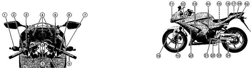
LOCATION OF PARTS
|
|
|
|
|
TD011418 G |
|
|
10. |
Front Fork |
15. Battery |
20. Radiator |
|
TD01140B G |
11. Headlight |
16. Seat Lock |
21. Shift Pedal |
|
|
|
12. |
Turn Signal Light |
17. Tool Kit |
22. Side Stand Switch |
1. Clutch Lever |
6. Right Handlebar Switches |
13. |
Spark Plugs |
18. Tying Hooks |
23. Side Stand |
2. Left Handlebar Switches |
7. Front Brake Lever |
14. Idle Adjusting Screw |
19. Wheel |
24. Drive Chain |
|
3. Starter Lockout Switch |
8. Ignition Switch/Steering Lock |
|
|
|
|
4. Meter Instruments |
9. Throttle Grip |
|
|
|
|
5. Brake Fluid Reservoir (Front) |
|
|
|
|
|
16 LOCATION OF PARTS
|
|
|
|
TD01142B G |
25. License Plate Light |
31. Fuel Tank |
36. |
Brake Disc |
|
26. Tail/Brake Light |
32. |
Fuel Tank Cap |
37. |
Brake Fluid Reservoir |
27. Passenger's Seat |
33. |
Radiator Cap |
|
(Rear) |
28. Fuse Box |
34. Muffler |
38. |
Rear Brake Light |
|
29. Rider's Seat |
35. Brake Caliper |
|
Switch |
|
30. Air Cleaner |
|
|
39. |
Rear Shock Absorber |
|
|
|
40. |
Rear Brake Pedal |
41. Oil Level Gauge
42. Coolant Reserve Tank
LOADING INFORMATION 17
LOADING INFORMATION
WARNING
Incorrect loading, improper in stallation or use of accessories, or modification of your motorcy cle may result in an unsafe rid ing condition. Before you ride the motorcycle, make sure that the motorcycle is not overloaded and that you have followed these instructions.
With the exception of genuine Kawasaki Parts and Accessories, Kawasaki has no control over the design or application of accessories. In some cases, improper installation or use of accessories, or motorcycle modification, will void the motorcycle
warranty, can negatively affect per formance, and can even be illegal. In selecting and using accessories, and in loading the motorcycle, you are personally responsible for your own safety and the safety of other persons involved.
NOTE
ОKawasaki Parts and Accessories have been specially designed for use on Kawasaki motorcycles. We strongly recommend that all parts and accessories you add to your motorcycle be genuine Kawasaki components.
Because a motorcycle is sensitive to changes in weight and aerodynamic forces, you must take extreme care
18 LOADING INFORMATION
in carrying cargo, passengers and/or in the fitting of additional accessories. The following general guidelines have been prepared to assist you in making your determinations.
1.Any passenger should be thoroughly familiar with motorcycle operation. The passenger can affect control of the motorcycle by improper positioning during cornering and sudden movements. It is important that the passenger sit still while the motorcycle is in motion and not interfere with the operation of the motorcycle. Do not carry animals on your motorcycle.
2.You should instruct any passenger before riding to keep his feet on the passenger footpegs and hold on to the operator, seat strap or grab rail. Do not carry a passenger unless he
or she is tall enough to reach the footpegs and footpegs are provided.
3.All baggage should be carried as low as possible to reduce the effect on the motorcycle center of gravity. Baggage weight should also be distributed equally on both sides of the motorcycle. Avoid carrying baggage that extends beyond the rear of the motorcycle.
4.Baggage should be securely attached. Make sure that the baggage will not move around while you are riding. Recheck baggage security as often as possible (not while the motorcycle is in motion) and adjust as necessary.
5.Do not carry heavy or bulky items on a luggage rack. They are designed for light items, and overloading can affect handling due to changes in weight distribution and aerodynamic forces.
6.Do not install accessories or carry baggage that impairs the performance of the motorcycle. Make sure that you have not adversely affected any lighting components, road clearance, banking capability (i.e., lean angle), control operation, wheel travel, front fork movement, or any other aspect of the motorcycle's operation.
7.Weight attached to the handlebar or front fork will increase the mass of the steering assembly and can result in an unsafe riding condition.
8.Fairings, windshields, backrests, and other large items have the capability of adversely affecting stability and handling of the motorcycle, not only because of their weight, but also due to the aerodynamic forces acting on these surfaces while the motorcycle is in operation. Poorly
LOADING INFORMATION 19
designed or installed items can result in an unsafe riding condition.
9.This motorcycle was not intended to be equipped with a sidecar or to be used to tow any trailer or other vehicle. Kawasaki does not manufacture sidecars or trailers for motorcycles and cannot predict the effects of such accessories on handling or stability, but can only warn that the effects can be adverse and that Kawasaki cannot assume responsibility for the results of such unintended use of the motorcycle. Furthermore, any adverse effects on motorcycle components caused by the use of such accessories will not be remedied under warranty.
Maximum Load
Weight of rider, passenger, baggage, and accessories must not exceed 170 kg (375 lb).
20 GENERAL INFORMATION
G E N E R AL INFORMATION
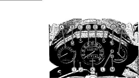
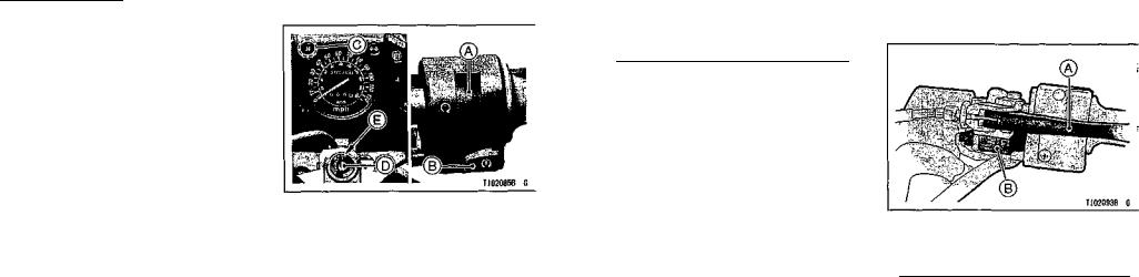
Meter Instruments
A.Tachometer
B.Oil Pressure Warning Light
C.Neutral Indicator Light
D.Speedometer
E.Odometer
F.Turn Signal Indicator Light
G.High Beam Indicator Light
H.Coolant Temperature Gauge
I.Red Zone
J.Reset Button
K.Trip Meter
L.Fl Indicator Light
M.Fuel Level Warning Light
Speedometer and Tachometer
The speedometer shows the speed of the vehicle. In the speedometer face are the odometer and trip meter. The odometer shows the total distance that the vehicle has been ridden. The trip meter shows the distance traveled since it was last reset to zero. The trip meter can be reset to zero by pushing the reset button.
The tachometer shows the engine speed in the revolutions per minute (r/min, rpm). On the right side of the tachometer face is a portion called the "red zone." Engine r/min (rpm) in the red zone is above maximum recommended engine speed and is also above the range for good performance.
GENERAL INFORMATION 21
CAUTION
Engine r/min (rpm) should not be allowed to enter the red zone; operation in the red zone will overstress the engine and may cause serious engine damage.
Coolant Temperature Gauge
This gauge shows the temperature of coolant. Ordinarily, the needle should stay within the scaled zone. If the needle reaches the red zone (marked "H"), stop the engine and check the coolant level in the reserve tank after the engine cools down.
Warning/Indicator Lights
c er.: The oil pressure warning light goes on whenever the oil pressure is dangerously low or the ignition key is in the ON position with the engine not running, and goes off when the engine
22 GENERAL INFORMATION
oil pressure is high enough. Refer to the Maintenance and Adjustment chap ter for more detailed engine oil informa tion.
 : When the headlight is on high beam, the high beam indicator light is lit.
 : When the turn signal switch is turned to left or right, the turn signal indicator light flashes on and off.
N : When the transmission is in neutral, the neutral indicator light is lit.
Fl: The fuel injection (Fl) warning light goes on when the ignition key is turned to "ON" and goes off soon after en suring that its circuit functions properly.
The warning light also goes on when ever the troubles occur in digital fuel injection system (DF1). If the warning light comes on, have the DFI system checked by an authorized Kawasaki dealer.
 The fuel level indicator light goes on when the ignition key is turned to "ON" and goes off soon after ensuring that its circuit functions properly. The warning light also goes on when 4.0 L (0.9 US gal) of fuel remains. Refuel at the earliest opportunity when the fuel level indicator light is still on with the engine running.
Key
This motorcycle has a combination key, which is used for the ignition switch/steering lock, seat lock, and fuel tank cap.
Blank keys are available at your Kawasaki dealers. Ask your dealer to make any additional spare keys you may need, using your original key as a master.
GENERAL INFORMATION 23
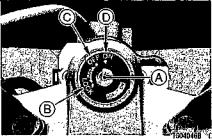
Ignition Switch/Steering Lock
This is a three-position, key-operated switch. The key can be removed from the switch when it is in the OFF or LOCK position.
A.Ignition Switch/Steering Lock
B.LOCK position
СOFF position
D.ON position
24 GENERAL INFORMATION
OFF |
Engine off. All electrical |
|
circuits off. |
||
|
||
|
|
|
ON |
Engine on. All electrical |
|
equipment can be used. |
||
|
||
|
|
|
LOCK |
Steering locked. Engine off. |
|
All electrical circuits off. |
||
|
||
|
|
NOTE
ОThe tail and license plate lights are on whenever the ignition key is in the ON position. One headlight goes on when the starter button is released after starting the engine. To avoid battery discharge, always start the engine immediately after turning the ignition key to "ON".
To lock the steering:
2.For locking, push down the key in the OFF position and turn it to LOCK position.
3.Pull the key out.
NOTE
О If the steering is hard to lock, turn the handlebar slightly to the left or the right.
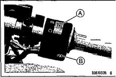
Right Handlebar Switches Engine Stop Switch:
In addition to the ignition switch, the engine stop switch must be in
the о position for the motorcycle to operate.
The engine stop switch is for emer gency use. If some emergency re quires stopping the engine, move the engine stop switch to the К position.
GENERAL INFORMATION 25
NOTE
О Although the engine stop switch stops the engine, it does not turn off all the electrical circuits. Ordinarily, the ignition switch should be used to stop the engine.
A.Engine Stop Switch
B.Starter Button
1. Turn the handlebar fully to the left.
26 GENERAL INFORMATION
Starter Button:
The starter button operates the elec tric starter when the transmission is in neutral.
Refer to the Starting the Engine sec tion of the "How to Ride the Motorcycle" chapter for starting instructions.
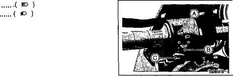
Left Handlebar Switches Dimmer Switch:
High or low beam can be selected with the dimmer switch. When the headlight is on high beam (  ), the high beam indicator light is lit.
High beam Low beam
NOTE
О When the headlight is on high beam, both head lights are lit. When the headlight is on low beam, only one headlight is lit.
GENERAL INFORMATION 27
Turn Signal Switch:
When the turn signal switch is turned
to the left (  ) or right (
  ), the corresponding turn signal flashes on and off.
To stop flashing, push the switch in.
Horn Button:
When the horn button is pushed, the horn sounds.
A.Dimmer Switch
B.Turn Signal Switch C. Horn Button
28 GENERAL INFORMATION
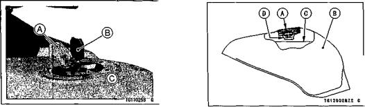
Fuel Tank Cap
To open the fuel tank cap, pull up the key hole cover. Insert the ignition key into the fuel tank cap and turn the key to the right.
To close the cap, push it down into place with the key inserted. The key can be removed by turning it to the left to the original position.
NOTE
ОThe fuel tank cap cannot be closed without the key inserted, and the key cannot be removed unless the cap is locked properly.
NOTE
ОDo not push on the key to close the cap, or the cap cannot be locked.
A.Key Hole Cover
B.Ignition Key
C.Fuel Tank Cap
Fuel Tank
Avoid filling the tank in the rain or where heavy dust is blowing so that the fuel does not get contaminated.
A.Tank Cap
B.Fuel Tank
СTop Level D. Filler Neck
GENERAL INFORMATION 29
WARNING
Gasoline is extremely flammable and can be explosive under cer tain conditions. Turn the igni tion key to "OFF". Do not smoke. Make sure the area is well ven tilated and free from any source of flame or sparks; this includes any appliance with a pilot light.
Never fill the tank so the fuel level rises into the filler neck. If the tank is overfilled, heat may cause the fuel to expand and overflow through the vents in the tank cap.
After refueling, make sure the fuel tank cap is closed securely. If gasoline is spilled on the fuel tank, wipe it off immediately.
30 GENERAL INFORMATION
Fuel Requirement:
Your Kawasaki engine is designed to use only unleaded gasoline.
CAUTION
Do not use leaded gasoline, as this will destroy the catalytic converter. (For further infor mation, refer to the "Catalytic Converter" section in the "How to Ride the Motorcycle" chap ter.)
Octane Rating
The octane rating of a gasoline is a measure of its resistance to detona tion or "knocking." The term commonly used to describe a gasoline's octane rating is the Research Octane Number
(RON). Always use a gasoline with an octane rating equal to, or higher than, RON 91.
NOTE
ОIf "knocking" or "pinging" occurs, use a different brand of gasoline or higher octane rating.
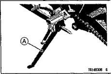
Stand
The motorcycle is equipped with a side stand.
GENERAL INFORMATION 31
Whenever the side stand is used, make it a practice to kick the stand fully up before sitting on the motorcycle.
NOTE
ОThe motorcycle is equipped with a side stand switch. This switch is de signed so that the engine does not start if the transmission is in gear and the side stand is down.
A. Side Stand
NOTE
ОWhen using the side stand, turn the handlebar to the left.

32 GENERAL INFORMATION
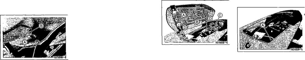
Seats
Passenger's Seat Removal
Remove the passenger's seat by in serting the ignition key into the seat lock, and turning it clockwise.
Pull up the rear of tha seat, and re move the passenger's seat by pushing it to the front.
A.Ignition Key B. Seat Lock
С Passenger's Seat
Rider's Seat Removal
•Remove the screw and the left and right side covers.
•Pull the left and right side covers to the front for detaching the stopper of the side cover from the holder at the fuel tank while pulling the projections out.
'Tai-7051B'G
A.Side Cover (Left Side) B. Screw
СProjections D. Holder
•Remove the bolts and pull off the seat to the up and rear.
®^ 7 ©
A.Bolt
B.Rider's Seat
С Pull Up and Rear
Seat Installation
Install the rider's and passenger's seats in the reverse order of removal.
GENERAL INFORMATION 33
Rider's Seat -
• Insert the tabs on the rear of the rider's seat into the slots on the frame and tighten the bolts.
A.Rider's Seat
B.Tabs
СSlots
D.Insert
• Install the left and right side covers and tighten screw.
34 GENERAL INFORMATION
NOTE
ОWhen installing the left and right side covers, fit the stopper of the side cover to the holder at the fuel tank, and insert the projections.
A.Stopper
B.Holder
Passenger's Seat -
•Insert the tab of the bracket into the slot in the rear of the passenger's seat.
•Insert the projection at the front of the passenger's seat into the slot on the frame.
• Push down the front part of the pas senger's seat until the lock clicks.
A.Projection
B.Slot
СTab
D. Insert
• Pull up the front and rear ends of the passenger's and rider's seats to make sure they are securely locked.
GENERAL INFORMATION 35
Helmet Hooks
Helmets can be secured to the mo torcycle using the helmet hooks located under the passenger's seat.
A. Helmet Hooks
36 GENERAL INFORMATION
WARNING
Do not ride the motorcycle with helmets attached to the hooks. The helmets could cause an accident by distracting the operator or interfering with normal vehicle operation.
Tool Kit
The tool kit is located under the passenger's seat.
Store the tool kit in the compartment provided. The kit contains tools that can be helpful in making roadside repairs, adjustments, and some maintenance procedures explained in this manual.
The tool kit should be fixed by the tool kit cover.
GENERAL INFORMATION 37
Tying Hooks
When tying up light loads to the seat, use the tying hooks located on the left and right sides of the rear fairing.
A.Tool Kit
B. Tool Kit Cover
A. Tying Hooks

38 BREAK-IN
BREAK-IN
The first 1,600 km (1,000 mi) that the motorcycle is ridden is designated as the break-in period. If the motorcycle is not used carefully during this period, you may very well end up with a "broken down" instead of a "broken in" motorcycle after a few thousand kilometers.
The following rules should be observed during the break-in period.
• The table shows maximum recommended engine speed during the break-in period.
|
Distance traveled |
Maximum engine speed |
|
|
|
|
0 ~ 800 km (0 ~ 500 mi) |
4 000 r/min (rpm) |
|
|
|
|
800 ~ 1 600 km (500 ~ 1 000 mi) |
6 000 r/min (rpm) |
|
|
|
• |
Do not start moving or race the engine immediately after starting it, even if the |
|
|
engine is already warm. Run the engine for two or three minutes at idle speed to |
|
|
give the oil a chance to work up into all the engine parts. |
|
• |
Do not race the engine while the transmission is in neutral. |
|
BREAK-IN 39
WARNING
New tires are slippery and may cause loss of control and injury.
A break-in period of 160 km (100 miles) is necessary to establish normal tire traction. During break-in, avoid sudden and maximum braking and acceleration, and hard cornering.
In addition to the above, at 1 000 km (600 mi) it is extremely important that the owner have the initial maintenance service performed by an authorized Kawasaki dealer.
40 HOW TO RIDE THE MOTORCYCLE
H OW TO RIDE THE MOTORCYCLE
Starting the Engine
• Check that the engine stop switch is in the о position.
•Turn the ignition key to "ON".
•Make sure the transmission is in neu tral.
A. Engine Stop Switch
B. Starter Button
C. Neutral Indicator Light
D. Ignition Switch
E. ON position
NOTE
О The motorcycle is equipped with a vehicle-down sensor, which causes the engine to stop automatically.
• Leaving the throttle completely closed, push the starter button.
CAUTION
Do not operate the starter con tinuously for more than 5 sec onds or the starter will overheat and the battery power will drop temporarily. Wait 15 seconds between each operation of the starter to let it cool and the bat tery power recover.
NOTE
О The motorcycle is equipped with a starter lockout switch. This switch is designed so that the engine does not start if the transmission is in gear and the side stand is down. However, the engine can be started if the clutch
HOW TO RIDE THE MOTORCYCLE 41
lever is pulled and the side stand is fully up.
A.Clutch Lever
B.Starter Lockout Switch
CAUTION
Do not let the engine idle longer than five minutes, or engine overheating and damage may occur.
 Loading...