


UFS 822si
Table of contents
 Loading...
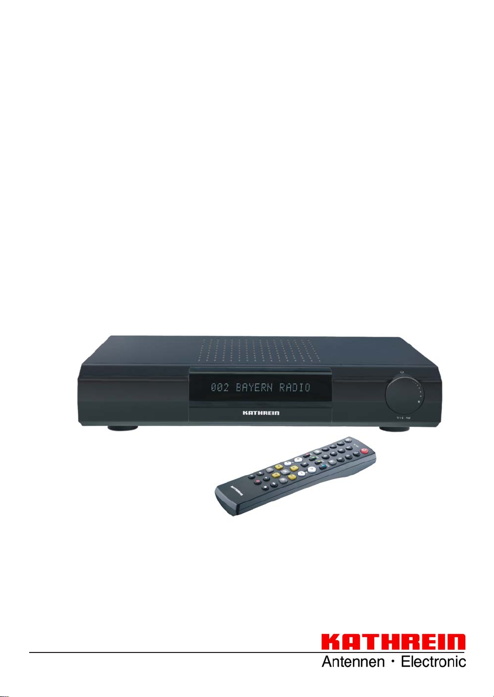
Operating manual
Twin-PVR Satellite Receiver
UFS 822sw/822si
with hard disk and Ethernet

PREFACE
Dear customer,
this operating manual is intended to help you make the fullest use of the extensive range of functions offered
by your new satellite receiver.
We have tried to make the operating instructions as easy as possible to understand, and to keep them as
concise as possible. To help you understand particular specialist terms that cannot be translated, we have
added a short glossary at the end of the manual.
The power switch is an environmentally friendly feature. If you will not be using your receiver for a longer
period, you should use the power switch to disconnect it from the power supply and save energy . For shorter
breaks, you can use the remote control to switch the receiver to standby , which uses only a minimal amount
of energy.
We wish you good reception and much pleasure using your new PVR satellite receiver.
Your
KA THREIN Team
2

CONTENTS
PREFACE .............................................................................................................................. ... 2
CONTENTS ............................................................................................................................... 3
IMPORTANT INFORMATION ...................................................................................................... 4
SAFETY INSTRUCTIONS - IMPORTANT NOTES ........................................................................ 6
RECEIVER FEATURES/SCOPE OF SUPPLY ............................................................................... 7
CONTROLS, DISPLAYS AND CONNECTIONS ............................................................................ 8
CONNECTION AND SET-UP ...................................................................................................... 9
REMOTE CONTROL ................................................................................................................ 13
FIRST INSTALLATION ............................................................................................................. 15
MENU TREE ........................................................................................................................... 28
OPERATING INSTRUCTIONS .................................................................................................. 29
ON-SCREEN DISPLAYS (OSD) ................................................................................................ 31
COMMON INTERFACE ............................................................................................................ 34
SYSTEM SETUP...................................................................................................................... 37
USER PREFERENCES ............................................................................................................ 50
VIDEOTEXT (TELETEXT) ......................................................................................................... 58
ORGANIZE CHANNELS ........................................................................................................... 59
TWIN FUNCTIONS .................................................................................................................. 65
TIMESHIFT ............................................................................................................................. 67
TVTV EPG AND TIMER ............................................................................................................ 68
AUDIO SETTINGS ................................................................................................................... 81
RECORDING ........................................................................................................................... 83
RECORDING LIST ................................................................................................................... 87
MULTIMEDIA/GAMES ............................................................................................................ 104
INSTALLATION MENU ............................................................................................................ 114
CONNECTING UP THE VIDEO/PVR ....................................................................................... 127
SOFTWARE AND PROGRAMME LIST UPDATE ...................................................................... 128
PVR MANAGER .................................................................................................................... 132
USING THE FRONT PANEL ................................................................................................... 133
RECEIVER TO RECEIVER DATA TRANSFER ......................................................................... 134
TECHNICAL APPENDIX ......................................................................................................... 135
SHORT TECHNICAL GUIDE .................................................................................................. 147
TROUBLESHOOTING ............................................................................................................ 150
SUBJECT INDEX ................................................................................................................... 151
SERVICE .............................................................................................................................. 155
3

IMPORTANT INFORMATION
The channels available on the satellites and transponders are subject to continual change. In such cases, it is
necessary to reset the channels as the factory preset programming corresponds to the situation on the date
of manufacture. The information for these settings can be found on the Internet or in relevant magazines.
Your receiver is factory fi tted with the latest software version. We are, however, constantly working on
adapting the software to the wishes of our customers and to developments in technology . The “Software and
Programme List Update” section contains additional information.
To connect your PC/laptop to the receiver over the network and to use the functions of the PVR
Manager , you must have unlimited rights (administrator rights) on your PC/laptop and on your network.
Please keep the original packaging in case you need to return the product at any time!
Due to their design, hard disks are liable to damage by impacts; they are adequately protected within
the receiver only when it is in its original packaging.
If the product is not properly packed, the warranty on the hard disk is invalidated.
Any modifi cations to the receiver software, or the use of applications not provided by Kathrein, will
invalidate the warranty!
You will have to bear the costs yourself for dispatching and repairing any receiver that requires
attention due to modifi cations to the software and use of applications other than those provided by
Kathrein!
Therefore exclusively use only software and applications provided by Kathrein for your receiver.
These are available by downloading from the satellite or from our Internet pages (www.kathrein.de).
Make a note of the receiver's basic settings, so as to be able to restore them if necessary!
Make sure that neither the fans on the device‘s rear panel nor the ventilation slits are covered or
blocked. If so, the device may overheat. Fire hazard!
Included in the software for this receiver is software that is licensed under the GNU (General Public
Licence). The source code of the program is obtainable under: http//:www.kathrein.de/linux/receiver/
ufs822/
DiSEqC™ is a trademark of Eutelsat.
4
IMPORTANT INFORMATION
REFERENCE NOTE ON AUDIO MPEG INC. AND S.I.SV.EL, S.P.A:
This device employs legally protected technologies which are protected by patents in the USA as well as by
intangible property laws in other countries.
Audio MPEG Inc. and Societa‘ Italiana per lo sviluppo dell‘elettronica, S.I.SV.EL, S.P.A, have granted
KA THREIN-W erke KG rights of use which are subject to certain restrictions. These restrictions must also be
observed by you as a customer.
According to these, this device is only to be used by end customers for private, non-commercial purposes
and for licensed content. Use for commercial purposes is not authorised. Utilisation of products or procedures sold or used with this device are not comprehended. With reference to licensed technologies, application of reversible procedures as well as dismantling of the device are both not permitted.
ONE-TOUCH RECORDING ON EXTERNAL USB STORAGE MEDIA
Die USB interface on the receiver front panel is not intended for connection of USB storage media!
To directly record a broadcast with the UFS 822 on an external USB storage medium (e.g. external hard
disk) with USB port), die Sie an die USB 2.0 Host-Schnittstelle an der Rückseite des Receivers anschließen
können, ist folgendes unbedingt zu beachten:
Please observe that the receiver only transmits a current of 500mA on the USB 2.0
socket. For some hard disks, this is not suffi cient to guarantee fl awless operation. To
guarantee optimal power supply to the hard disk, use an external hard disk with its
own power supply or insert a USB 2.0 hub with its own power supply.
The recording function is only valid for One T ouch Recording (OTR). Programming via
EPG is not possible!
5
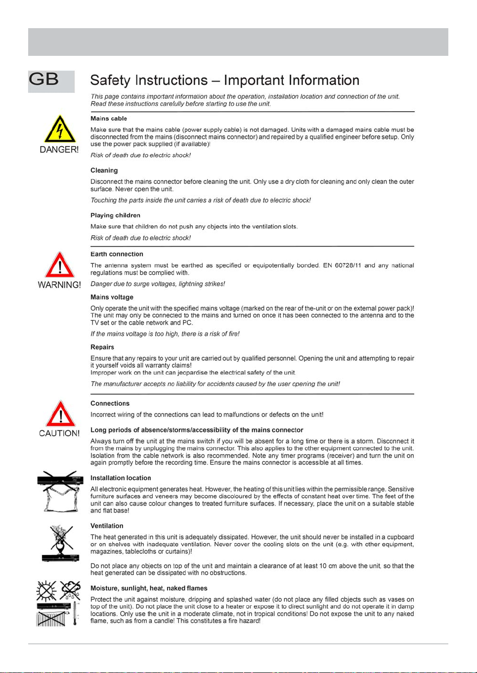
SAFETY INSTRUCTIONS - IMPORTANT NOTES
6

RECEIVER FEATURES/SCOPE OF SUPPLY
The UFS 822 multi-functional satellite receiver is fi tted with two independent reception and signal
processing systems as well as a computer hard disk with a capacity of 160 GByte, allowing one to
download over 100 hours of TV and radio programmes, and to view these as often as wanted without any
loss in quality, either at the same time or time-delayed (timeshift function).
The integrated Common Interface can accommodate two CA modules to enable viewing of additional PayTV channels. The receiver‘s 16-digit alphanumeric display shows the channel names, while 16 status icons
inform you on the current receiver state (e.g. Dolby Digital, timer, ...)
The HDMI interface allows one to connect the receiver to the HDMI interface on an HDMI-capable screen
for optimal viewing comfort. A video composite connection and two Scart connections are additionally
provided. The receiver is fi tted with an optical audio output so that the Dolby Digital data stream AC 3 can
be transmitted to a Dolby Digital stereo system.
USB 2.0 host: Playback of MP3 fi les, JPEG fi les and recordings; recording on external storage
medium, formatting of external USB devices, use for service purposes (updating
software)
Ethernet port: Playback of MP3 fi les, JPEG fi les and recordings, VLC streaming, software
update and channel list editing using a PC/Laptop.
The „File Sharing“ feature is enabled using the programme “MFServer”, which is integrated in the PVR
Manager. The programme can be downloaded free of charge from the Kathrein website.
The professionally edited tvtv EPG provides free information on over 60 programmes without requiring
bothersome channel change-over, even up to one week in advance.
The receiver‘s operational system is LINUX based. The receivers are available in silver and black.
PRODUCT PACKAGE
- UFS 822si and UFS 822sw
- Remote control RC 660
- Scart cable
- Coaxial loop-through cable for loop-through operation
- 2 Batteries AAA 1.5 V
- Power supply cable
- Operating Manual
7
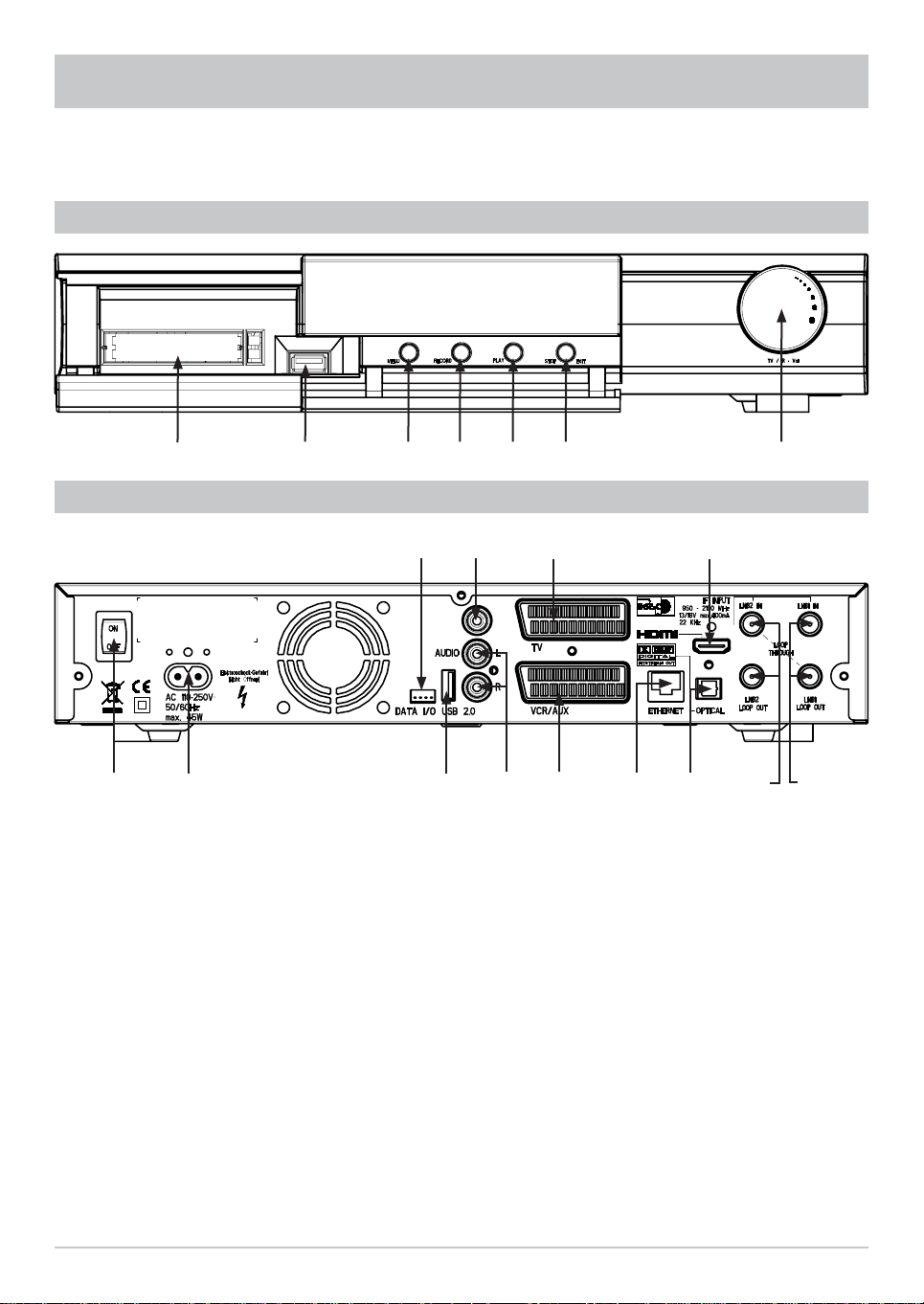
CONTROLS, DISPLAYS AND CONNECTIONS
This section provides a brief description of all the controls, displays and connections. The key symbols
presented here can also be found in the description of the operating steps.
VIEW OF FRONT PANEL (FLAP FOLDED DOWN)
VIEW OF REAR PANEL
Front panel controls and displays
1. Common Interface for two CA modules for
Pay-TV cards *
2. USB 1.1 port
3. Menu button to call up or exit menus or submenus
4. Record button to start recording manually
5 Play button to start playback manually
6. Stop/Exit button to stop playback/recording
manually or exit the menus
7. Multifunction control
)
*
CA modules and Pay TV cards are not included
8
)
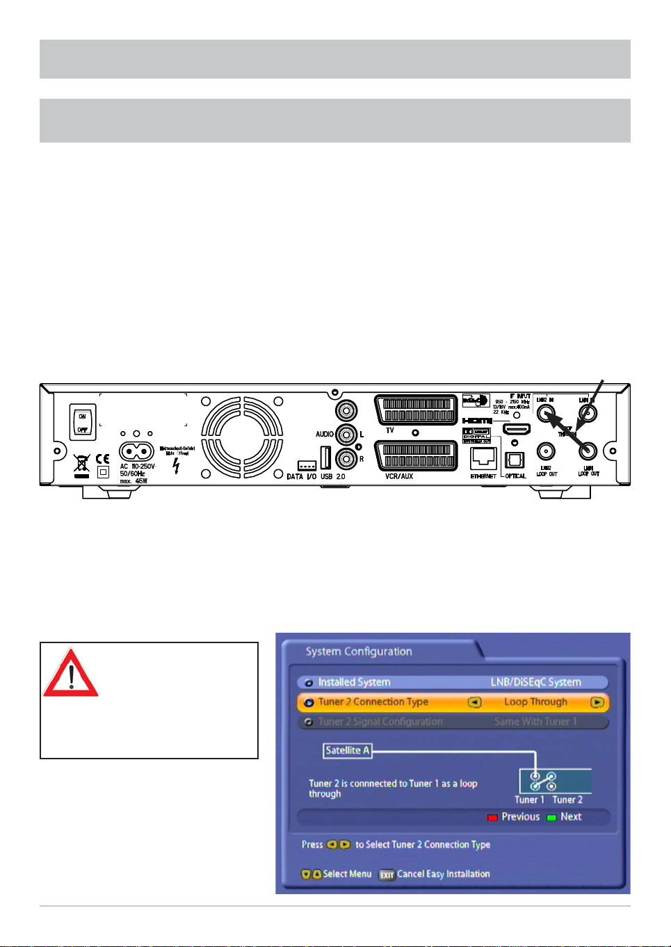
Rear panel controls and displays
1. On/Off switch (with mains disconnect)
2. Mains supply cable
3. Data interface (only for service)
4. Video output (composite colour)
5 USB 2.0 host port
6. Audio outputs (L/R) cinch sockets
7. Scart socket for TV connection
8. Scart socket for VCR-/AUX connection
9. Network connection (Ethernet)
10. HDMI connection
11. Optical data stream output (SPDIF/Sony
Philips Digital Interface Format) for Dolby
Digital AC 3 audio
12. LNB 2 input and loop-through output
13. LNB 1 input and loop-through output
CONNECTION AND SET-UP
The following section is intended specifi cally for specialist dealers. You only need read this section if you
are performing the installation yourself.
The “Connection Examples” section provides a sample confi guration.
Do not connect the unit to the mains until all installation work has been properly carried out.
Refer to the information in the “Safety Instructions” section.
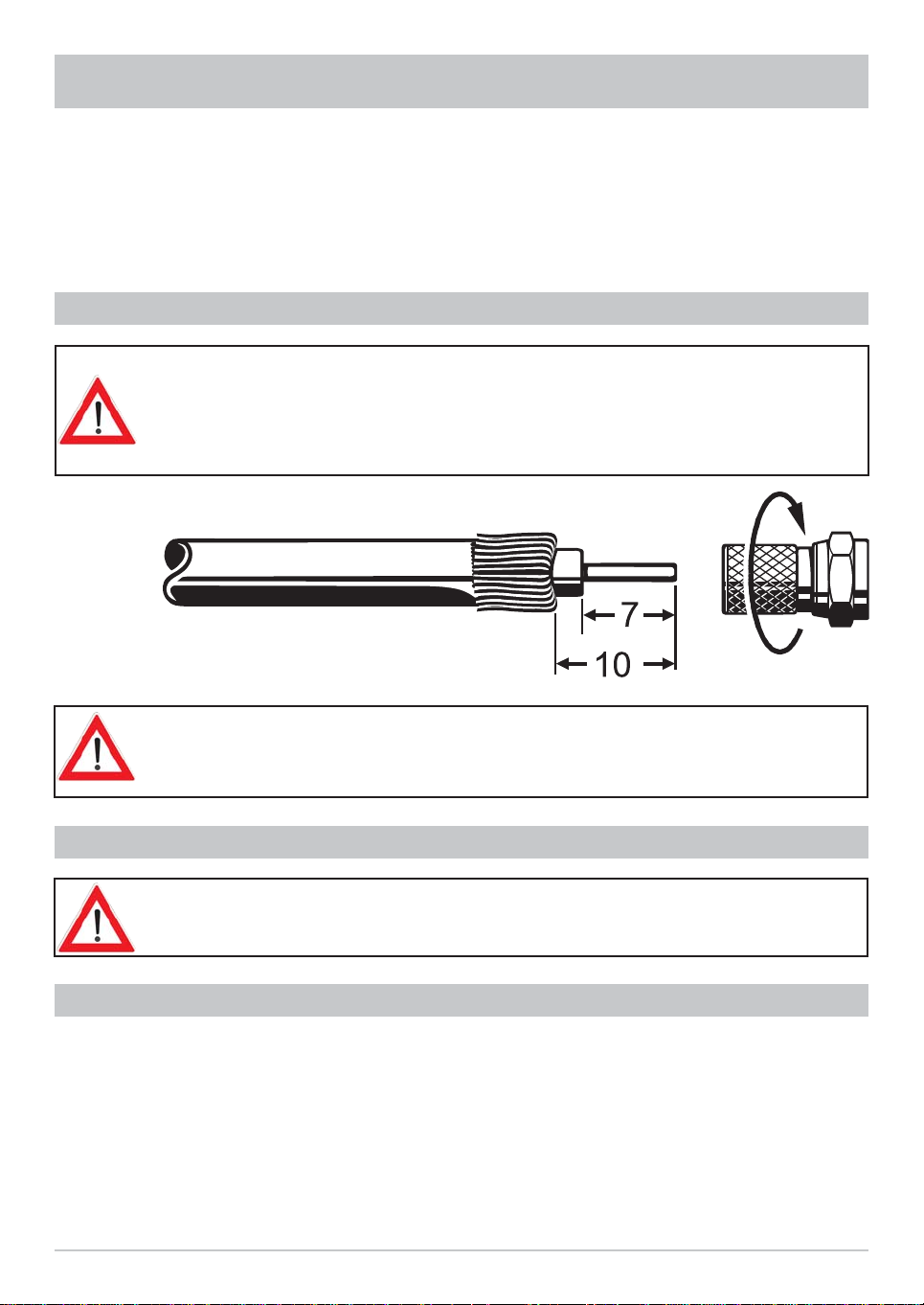
CONNECTING THE UNIT (SAT-IF CONNECTIONS)
Connect the Sat IF inputs on the receiver to the satellite reception system. Use coaxial
cable with a standard F connector.
If the F standard connectors are not yet fi tted on the cable, strip the insulation from
the cable as shown in the following illustration and carefully twist the F standard
connectors on to the ends of the cables until they are securely seated.
When fi tting the connector, make sure that no wires from the braid are touching the
inner conductor, so no short circuit can occur.
The quality of the reception signal depends on the connection!
RECEPTION REQUIREMENTS
Make sure that your own satellite antenna system is equipped at least with a
universal LNB for digital reception in the high-band range.
RECEPTION SYSTEM PRESETS
The presets for the control signals have been made for standard reception systems, i.e. 14/18 V for polarity
reversal and 22 kHz switching signal for low/high band changeover on multi-feed reception systems.
If tone-burst switch matrices are used in the reception system, the default selection in the installation menu,
Antenna Setup, Tuner 1 and Tuner 2, under “DiSEqC™ Switch”, must be changed. Refer to the “Installation
Menu” section on this, under “Antenna Setup”, “Tuner 1” and “Tuner 2”. Be sure to follow the operating
instructions for the matrix used.
9
CONNECTION AND SET-UP
INFORMA TION ABOUT ANTENNA CONNECTION AND “LOOP THROUGH”
OPERATION
To enable you to utilise all the reception and recording properties of your UFS 822 twin-PVR Sat receiver,
such as
1. recording one programme and at the same time viewing any other programme or zapping through the
channels, and
2. recording two different programmes at the same time,
the two tuner inputs of the Sat receiver must each be supplied with a dedicated satellite signal from the
antenna system/Sat outlet.
The receiver tuner inputs are factory preset on the installation menu to work with two separate Sat antenna
connections.
If you only have one antenna connection available, we recommend you interconnect the output of tuner 1
and the input of tuner 2 using the loop-through cable supplied.
Loop-through cable
For this, in “First Installation” for tuner input 2 select “Loop-through mode” (see “First Installation” section).
Press the
Installation”. Go through step-by-step until you get to Tuner Setup, you can make the settings here,
though a restriction on this is that with tuner 2 you can only receive the additional channels of the plane
currently set by tuner 1 (e.g. Horizontal High).
button to access the “Tuner Input” menu option, then choose “Installation” and “First
If you wish to operate
your UFS 822 on a singlecable system, please
refer to the connection
example for singlecable systems (see
“Connection Examples”)
10
CONNECTION AND SET-UP
This will only work when receiving one satellite, not in multi-feed reception!
If only tuner 1 is connected (with no connection to tuner 2), the “Single Mode” setting must be selected
for the tuner input. You then have only the facilities of a normal “single receiver” available to you.
If this setting is not made, malfunctions will occur and the following message will be displayed:
No signal!
To access the menu for the setting “Single Mode”, proceed as follows:
Main menu→ Installation → Antenna settings → Connection type
TV AND VIDEO RECORDER CONNECTION
Connect the satellite receiver (TV Scart socket) and the TV set using a Scart cable (see “Connection
Example”). If your TV has a stereo capability, you can receive the sound in stereo via the Scart connection.
Connect the satellite receiver (VCR/AUX Scart socket) and the video recorder/PVR likewise by a Scart
cable. For system reasons, the same video signals are to be found on the Scart outputs and on the video
cinch output.
If you are recording using an external video recorder, remember not to operate the
receiver during recording, otherwise all the on-screen displays will appear on your
recording.
AUDIO CONNECTION
If you want to play the sound on your hi-fi system, connect the audio cinch sockets to the input sockets on
the hi-fi system with an appropriate cable (see “Connection Example”).
OPTICAL DIGITAL OUTPUT
The fi bre-optic output is intended for the connection of a Dolby Digital system (see “Connection Example”).
11
CONNECTION AND SET-UP
INSERTING BATTERIES INTO THE REMOTE CONTROL
Remove the cover on the rear of the remote control.
Insert the two supplied batteries into the remote control. Ensure correct polarity of the
batteries; the + and - markings are indicated inside the battery compartment.
Slide the cover back into the housing until it locks in place.
Used batteries are special waste!
Do not throw spent batteries into your domestic waste; take them to a collection point for old
batteries!
DISPOSAL INSTRUCTION
Electronic equipment is not domestic waste - in accordance with directive 2002/96/EC OF THE
EUROPEAN PARLIAMENT AND THE COUNCIL dated 27
and electronic appliances, it must be disposed of properly.
At the end of its service life, take this unit for disposal to an appropriate offi cial collection
point.
th
January 2003 on used electrical
12
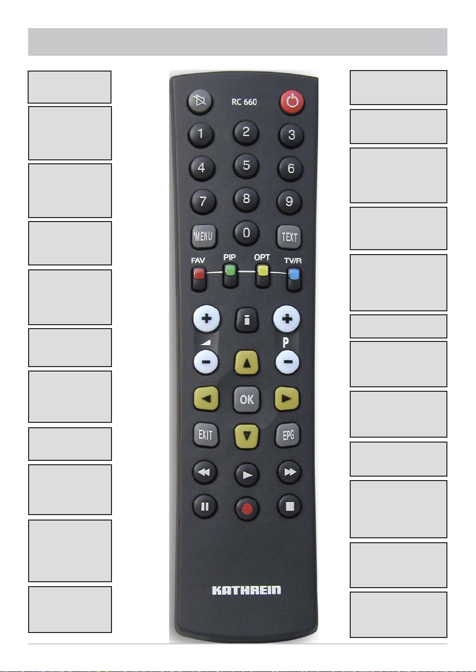
REMOTE CONTROL
Sound on/off
...
Number input for
channels, timers
etc.
Access main
menu
Exit menus
(red)
Access Favorites
list
(green)
!
Picture-in-picture
from 2nd tuner or
hard disk
%
Volume
Exit menu -
back to TV picture
Fast rewind
Playback
Hard disk contents
Pause (freeze-
frame)
Timeshift
Power/standby
Videotext (Teletext)
(yellow)
"
Access channel
options Sound/
subtitles selection
(blue)
#
Switch between
TV/radio
Access channel
notifi cation
Programme info
AV mode
&
Channel selection
up/down
Confi rm input
Access channel list
Cursor buttons
Access TVTV EPG
(Electronic
Programme Guide)
Fast forward
Display recordings
(red)
One-touch
recording
Stop recording/
playback
13

REMOTE CONTROL
REMOTE CONTROL RC 660
The RC 660 remote control supports up to four devices which are supplied with the RC 660 as standard.
First, switch off all other receivers (mains switch).
1. Setting via menu (as of software version 1.01)
For the UFS 822, the remote control code does not have to be entered manually . You can easily select one of
the four existing remote control codes in the menu (see menu “System setup”, “STB management”, “Remote
control code”).
Notice: As of software version 1.01, the remote control code can only be modifi ed through the menu.
Manual modifi cations will not be saved by the receiver.
2. Manual setting (only possible if the software version is older than 1.01)
Switch on the relevant receiver.
On the remote control simultaneously press
Address 1 =
Then switch the receiver off again at the power switch and do the same for the other
units (
+ + for the fourth receiver)
Make sure only one receiver is on at a time!
To switch the remote control to an infrared code:
When you have confi gured all receivers to their infrared code, to switch between units on the remote control
do the following:
For operating the fi rst receiver (address 1), press
+
, for the second receiver
for the fourth receiver
(red) = Kathrein UFD 5xx code for remote control RC 400
+
The RC 600 and RC 650 remote controls cannot be replaced!
+ +
+ + for the second receiver; + + for the third receiver and
+
.
+
, for the third receiver
+
and
14
FIRST INSTALLATION
Before using your unit for the fi rst time, read the “Safety Instructions” and
“Connection and Setup” sections.
The “Connection Examples” section provides a sample confi guration.
Do not connect the unit to the power supply until all installation work has been properly
carried out.
The guidance given in the “First Installation” section assumes that the receiver has
been properly connected, as per the “Safety Instructions” and “Connection and
Set-Up” sections.
First switch your TV set on and select the AV channel position. Switch on your receiver at the power switch
on the rear of the unit. The following screen appears:
Also pay attention
to the bars at the
bottom of the onscreen display!
These provide
information on what to do
next.
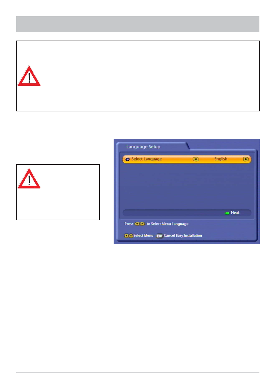
Select the menu language you want using the
Italian, Spanish, Polish, Dutch and French.
Press the
(green) button to move to the next menu.
!
buttons. Available options: German, English, Turkish,
15
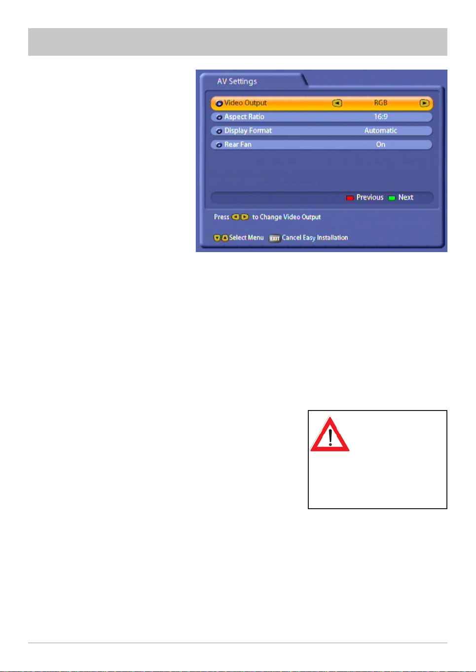
The following display appears:
FIRST INSTALLATION
Use the
Refer to the operating instructions for your television set!
Video Output
Here select the type of video signal at the Scart socket or HDMI socket. Select the signal that your TV set
can process.
- FBAS – composite colour baseband signal
(colour/picture/blanking/synchronisation signal)
- RGB – Red/Green/Blue signal
- Y/C – S-Video signal (luminance/chrominance) or
- YUV – component data
TV Type
Here select the TV's picture format. Either
- 4:3 format,
- 16:9 format or
- HDMI
Display Format
Select the screen display mode here:
- for TV type “4:3”: “Pan & Scan” or “Letter-Box”
- for TV type “16:9”: “Automatic” or “Always 16:9”
- for TV type “HDMI”: “Automatic” or “Always 16:9”
buttons here to select the settings for your TV set.
If during the First
installation it is
detected that
an HDMI device
is connected,
“HDMI” is automatically preselected as the TV type.
Rear fan
Here you can select whether the rear fan always runs whilst the unit is switched on “On” or whether the fan
will be switched on and off again at pre-programmed intervals “Scheduled”.
Press the
(green) button to move to the next menu.
!
16
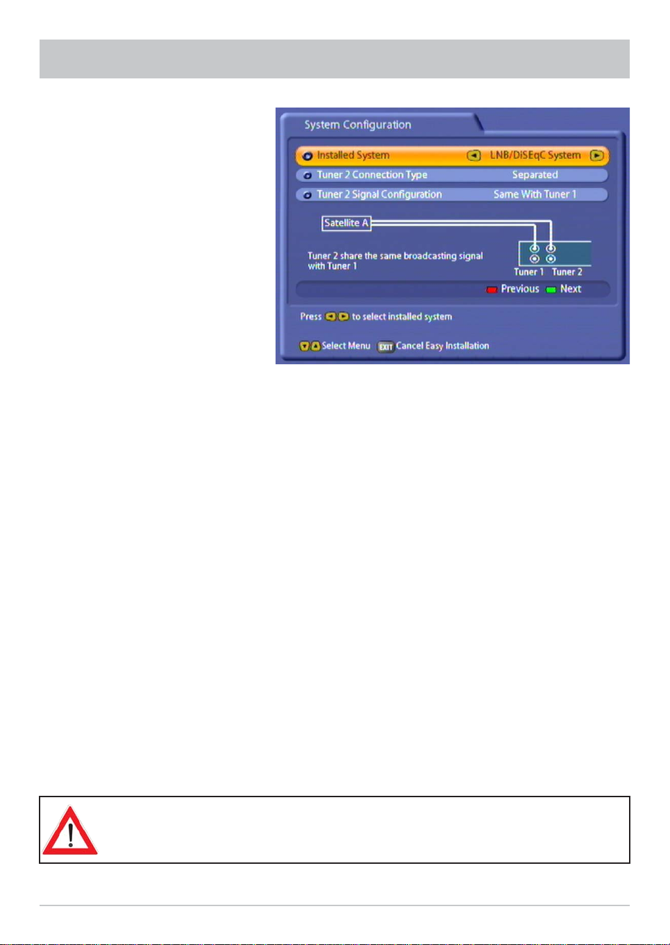
FIRST INSTALLATION
The following display appears:
Note: If you are unsure whether
you chose the right
option from a previous
menu, you can go back
a step at any time during
the First installation
process by pressing
the
(red) button.
Press the
the receiver by you or the engineer.
You have the following options:
Installed system
- “LNB/DiSEqC™ System”: Conventional satellite reception (simple digital satellite system)
- “Single-cable system”: Satellite reception using a “single-cable system” (functions at present only using
a single cable system from Kathrein!)
Connection type for tuner 2
- “Separated”: Tuner 2 (input) has its own signal input, i.e. a direct connection between the antenna socket
and the tuner 2 input
- “Loop-through”: The signal currently connected to the tuner 1 loop-through output is looped-through to
tuner 2 (input). Refer also to the section headed “Operation on one Antenna Connection”
Signal confi guration for tuner 2 (only in “Separated” connection type)
- As for tuner 1: Both tuners are connected to the same signal source (same cable from LNB)
- Different from tuner 1: The two tuners are connected to different signal sources (separate cables
from LNB)
Press the
menus are divided into two columns. The left-hand column indicates the further installation
procedure for the “Same with tuner 1”, signal confi guration, while the right-hand column details the
“Different to tuner 1” procedure. If your reception system is a “Single-cable” system from Kathrein,
continue the First installation as described on page 25.
buttons here to select the connection type and signal confi guration for the tuners set on
(green) button to move to the next menu. The notes on the subsequent First Installation
!
The satellites shown in the following screenshots are factory preset. To be able to
receive the satellites you want, your system must be aligned to them!
17
FIRST INSTALLATION
Signal confi guration
“As for tuner 1”
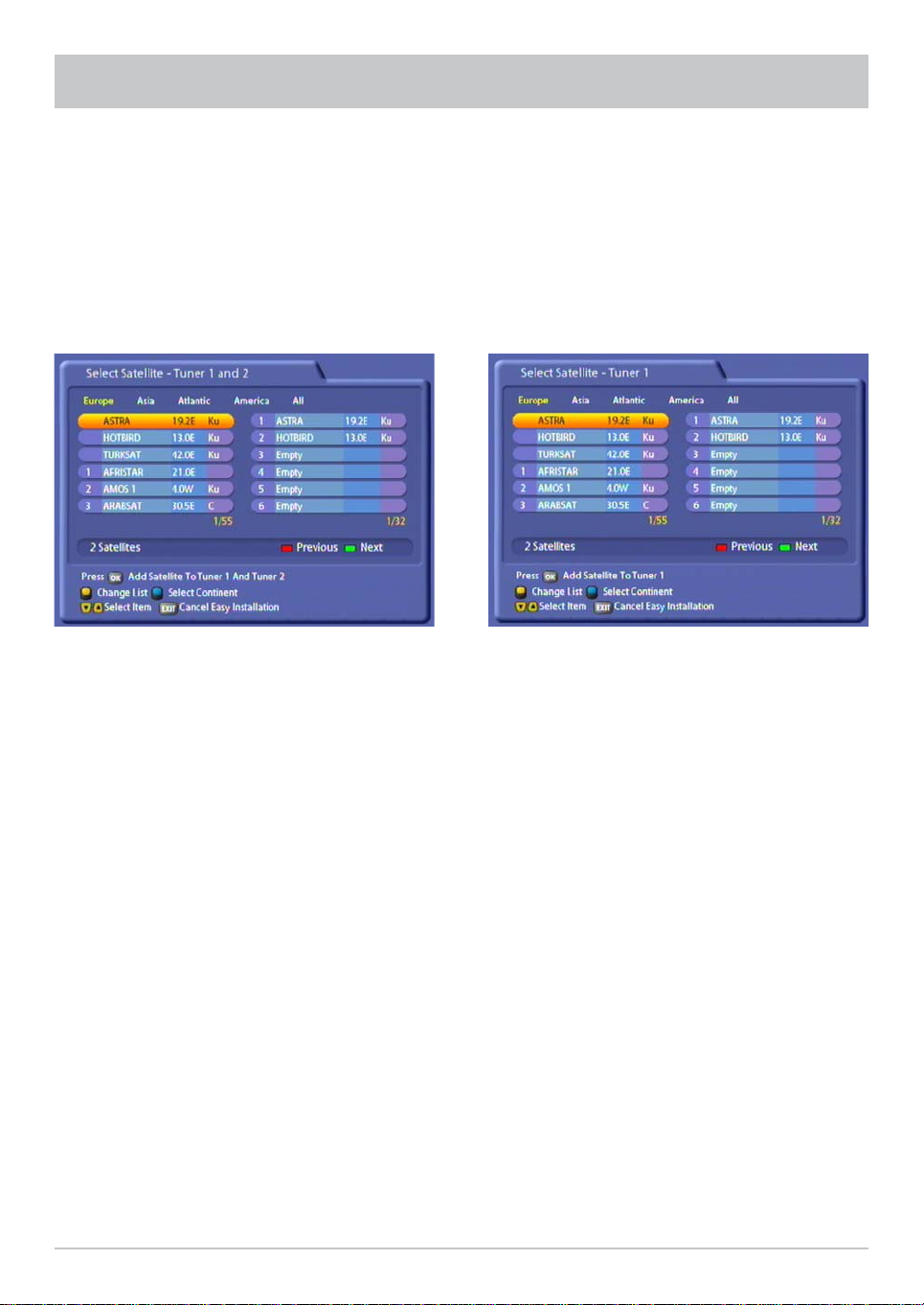
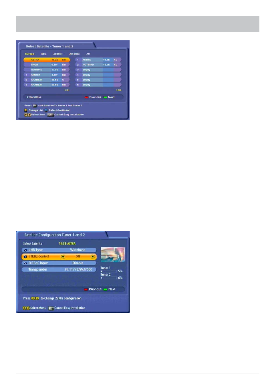
Press the # (blue) button to view the satellites by continent; that is, which satellites are accessible on which
continent. The continents are displayed above the list of satellite names. The selected continent is shown
in yellow.
The satellites from the pre-programmed channel list are automatically pre-entered in the right-hand column,
and can be changed/deleted according to your reception system.
Press the
select the satellites from which you want tuners 1
buttons and the button to
Press the
satellites you want tuner 1 to receive signals from.
Signal confi guration
“Different from tuner 1”
buttons and the to select the
and 2 to receive signals. Press the
confi rm your selection; the chosen satellite is then
moved into the tuner satellite list on the right.
If you have unintentionally transferred a satellite
into the list on the right, you can press the
(yellow) button to switch between the lists, and
"
then press the
concerned.
When you have selected all the satellites you want,
press the
18
!
button to remove the satellite
(green) button.
button to
Press the
the chosen satellite is then moved into the tuner
satellite list on the right.
If you have unintentionally transferred a satellite
into the list on the right, you can press the
(yellow) button to switch between the lists, and
"
then press the
concerned.
When you have selected all the satellites you want,
press the
button to confi rm your selection;
button to remove the satellite
(green) button.
!

FIRST INSTALLATION
Select here the satellites you want tuner 2 to
receive signals from, as you did for tuner 1.
When you have selected all the satellites you want,
Press the
button to select the satellite confi guration for each
satellite you previously selected.
LNB Type:
Press the
menu. Press the
selection. To confi rm your selection press the
button to open the LNB settings
buttons and the
buttons to make your
press the
Press the
button to select the satellite confi guration for each
satellite you previously selected.
LNB Type:
Press the
menu. Press the
selection. To confi rm your selection press the
(green) button.
!
button to open the LNB settings
buttons and the
buttons to make your
buttons to select “OK” and press the
button.
- Single (LNB Low frequency 9750 MHz)
- Dual (LNB Low frequency 9750 MHz and LNB
High frequency 10,600 MHz)
- Universal (LNB Low frequency 9750 MHz and
LNB High frequency 10,600 MHz and Limit
frequency 11,700 MHz)
buttons to select “OK” and press the
button.
- Single (LNB Low frequency 9750 MHz)
- Dual (LNB Low frequency 9750 MHz and LNB
High frequency 10,600 MHz)
- Universal (LNB Low frequency 9750 MHz and
LNB High frequency 10,600 MHz and Limit
frequency 11,700 MHz)
19

FIRST INSTALLATION
22kHz Control:
Press the
(On/Off). The 22kHz Control is needed to switch
LNBs in multi-feed reception and to switch between
Low and High band.
DiSEqC™ input:
Press the
- 1 of 4: for the fi rst satellite of the tuner
- 2 of 4: for the second satellite of the tuner
- 3 of 4: for the third satellite of the tuner
- 4 of 4: for the fourth satellite of the tuner
- Mini A: Tone-burst control signal 1 for the fi rst
satellite of the tuner (if reception system not
DiSEqC™-compatible)
- Mini B: Tone-burst control signal 2 for the
second satellite of the tuner (if reception system
not DiSEqC™-compatible)
- Disable: If your reception system is not
DiSEqC™-compatible and only one satellite
per tuner is selected.
buttons to make your selection
buttons to make your selection.
20
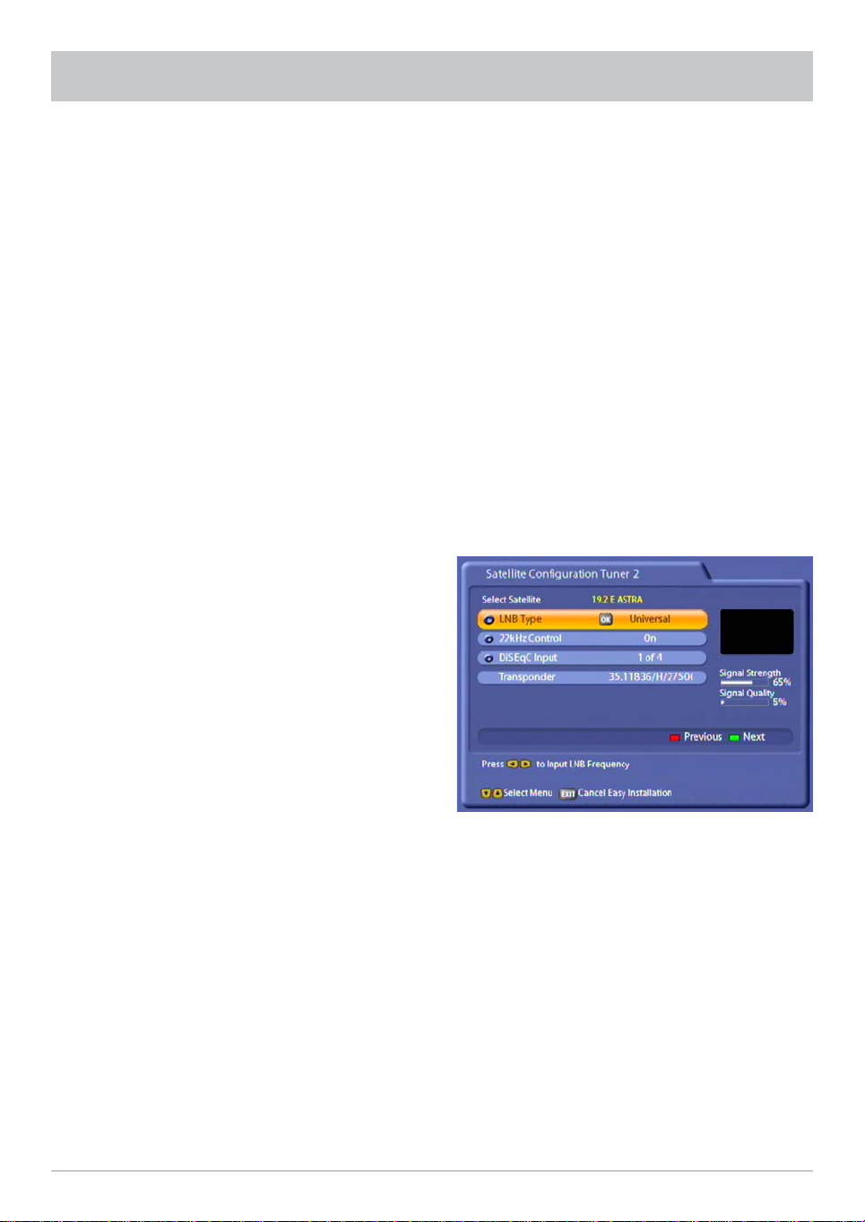
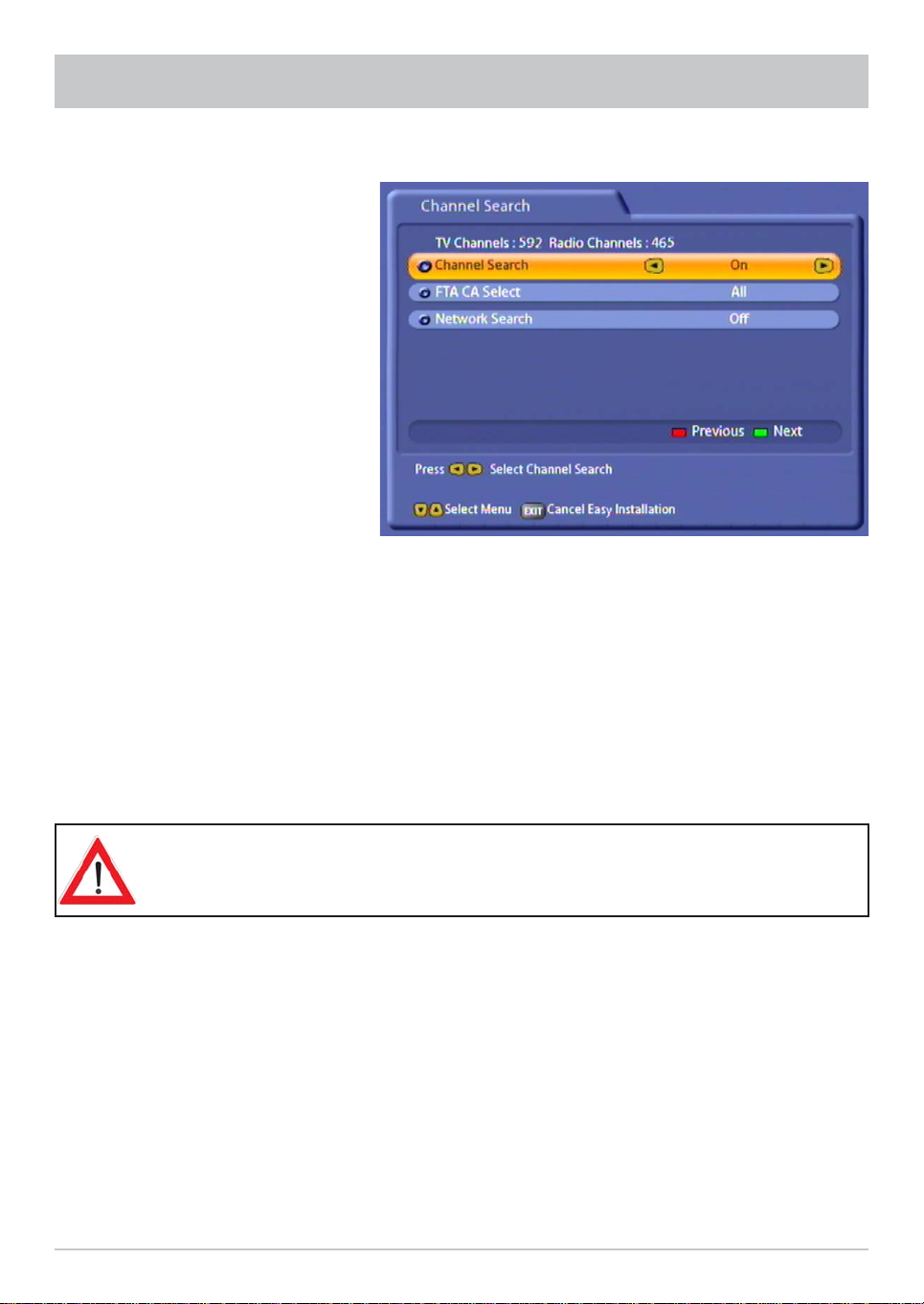
FIRST INSTALLATION
Transponder:
Press the
transponders of the satellite highlighted in yellow
at the top of the display. At the right you will see
the signal strength of the transponder on the two
tuners, enabling you to check that the satellite
confi guration you just set up is OK.
When you have fi nished confi guring the satellite,
press the
If in the preceding “Select Satellite” menu you
selected more than one satellite, you will now
see the confi guration for the next of the satellites
you selected. Confi gure the satellite as described
above.
When you have fi nished confi guring the satellite,
press the
automatically calls up the selection menu for the
channel search.
!
buttons to scroll through the
(green) button.
(green) button. The receiver then
!
Transponder:
Press the
transponders of the satellite highlighted in yellow
at the top of the display. At the right you will see
the signal strength of the transponder on the two
tuners, enabling you to check that the satellite
confi guration you just set up is OK.
When you have fi nished confi guring the satellite,
press the
If in the preceding “Select Satellite” menu you
selected more than one satellite, you will now
see the confi guration for the next of the satellites
you selected. Confi gure the satellite as described
above.
When you have confi gured all the satellites you
previously selected for tuner 1, you see the
satellite confi guration display for the second tuner
(see example screenshot):
!
buttons to scroll through the
(green) button.
Confi gure the satellites for the second tuner in the
same way as for tuner 1.
When you have fi nished confi guring the satellite,
press the
automatically calls up the selection menu for the
channel search.
(green) button. The receiver then
!
The notes on First installation are unifi ed once again from this point!
Continue First installation as described on page 25.
21
FIRST INSTALLATION
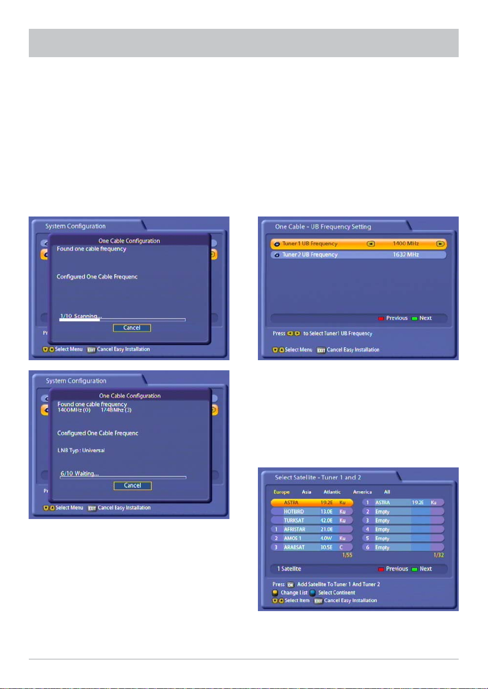
Single-cable system
“Automatic”
Note: If there already is a UFS 822 on the
system and a second UFS 822 is to be added,
the fi rst UFS 822 should be switched on and both
tuners should be active, so that the single-cable
frequencies for the fi rst receiver remain reserved.
The two receivers cannot share the same
frequencies.
Press the ! (green) button to continue with the installation.
Single-cable system
“Manual”
Note: If there already is a UFS 822 on the system
and a second UFS 822 is to be added, you
must assign different frequencies to the second
UFS 822 (otherwise the receivers will interfere with
each other).
A maximum of two UFS 822 receivers can be
connected to a 4-SCR system.
Display of the valid single-cable frequencies found
by the receiver (example):
Single-cable frequency 0–1400 MHz
Single-cable frequency 1–1516 MHz
Single-cable frequency 2–1632 MHz
Single-cable frequency 3–1748 MHz
The number of searches is limited to 10. If the
tenth search is performed and still no success, the
system switches to manual mode. It can however
be switched back into automatic mode.
22
Press the
single-cable frequencies to be used by your
receiver.
Then press the
screen.
!
buttons to set the two
(green) button to obtain the next
FIRST INSTALLATION
The receiver now checks whether two free
single-cable frequencies are available for the
receiver to use.
Display of the frequencies selected by the receiver
(example):
Single-cable frequency 0–1400 MHz
Single-cable frequency 1–1516 MHz
The receiver now automatically performs the
confi guration (setting the LNB frequency and the
LNB type).
Press the
select the satellites from which you want tuners
1 and 2 to receive signals. Press the
to confi rm your selection; the chosen satellite
is then moved into the tuner satellite list on
the right.
If you have unintentionally transferred a satellite
into the list on the right, you can press the
(yellow) button to switch between the lists, and
"
then press the
concerned.
When you have selected all the satellites you
want, press the
buttons and the button to
button to remove the satellite
(green) button.
!
button
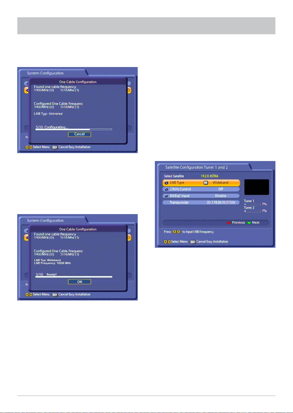
Once the automatic confi guration has been
completed, the received displays an overview for
you. Now press the
button.
If the LNB type used in your reception system
is a single-cable LNB, the setting must be
“Wideband” LNB. If a Universal LNB is used
with a single-cable matrix, the setting must be
“Universal” LNB (for this, refer to the product
information, user instructions and manuals for
the LNB and for the matrix).
For “LNB Type” perform here a suitable setting for
your reception system, “Wideband” or “Universal”.
The “22kHz Control” must be set to “Off” and the
“DiSEqC™ Input” must be set to “Disable”.
You can see whether the confi guration is correct
for your reception system by viewing the test
transponder signal strength (selection by pressing
the
buttons).
23
FIRST INSTALLATION
Press the
select the satellites from which you want tuners
1 and 2 to receive signals. Press the
to confi rm your selection; the chosen satellite
is then moved into the tuner satellite list on
the right.
If you have unintentionally transferred a satellite
into the list on the right, you can press the
(yellow) button to switch between the lists, and
"
then press the
concerned.
When you have selected all the satellites you
want, press the
buttons and the button to
button to remove the satellite
(green) button.
!
button
The “22kHz Control” must be set to “Off” and the
“DiSEqC™ Input” must be set to “Disable”.
You can see whether the confi guration is correct
for your reception system by viewing the test
transponder signal strength (selection by pressing
the
24
buttons).
FIRST INSTALLATION
The notes on First installation are unifi ed once again from this point!
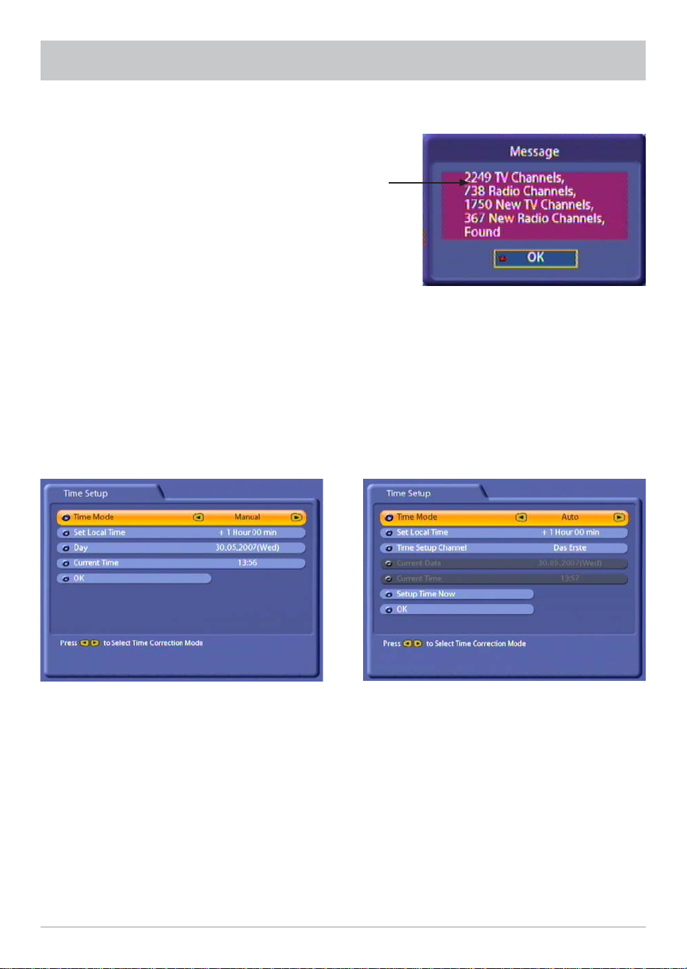
Perform the settings by pressing the
Channel Search
Press the
want to search for more/new channels.
FTA CA Select:
- All: FTA (free-to-air) and encoded channels are searched for
- Only FTA channels: Only non-encrypted channels, such as ZDF in Germany, are searched for
- Only encrypted channels: Only encrypted channels, such as Austria's ORF, are searched for
Network scan
If you set the network search to “Off”, only the factory stored transponders of the satellites you previously
selected will be scanned for new as yet unlisted channels.
If you set the network scan to “On”, the transponder network enables additional transponders that have not
yet been stored to be located. They are then stored and searched for new channels in the same way as the
existing transponders.
Press the
guided straight to the next item in the First installation process.
buttons to select whether you want to use the factory default channel list or whether you
Encrypted channels can be decoded only by using a CA module and corresponding
smart card. CA modules and smart cards are not supplied with this product. Please
contact your respective Pay-TV supplier.
(green) button to start the channel search, or if you set the channel search to “Off” you are
!
buttons.
25
FIRST INSTALLATION
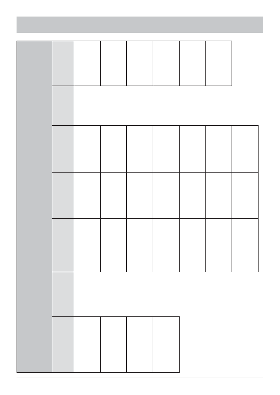
If the search is successful, you see the following message (example):
Number of channels found
Press the button to confi rm loading the newly found channels and move on to the next step in First
installation.
Here press the
• Manual or
• Auto (receiver takes time from preset channel)
buttons to select the time mode:
“Manual” time setting
Use the
settings.
buttons to make the
Use the
settings.
“Auto” time setting
buttons to make the
26

FIRST INSTALLATION
Set Local Time
Press the
UMTC (Universal Mean Time Coordinate;
formerly Greenwich Mean Time) and Winter/
Summer time. At the bottom of the screen you
see a listing of major cities to provide an indication
of which time zone you have just set. Example:
For Berlin (Germany) you need to enter +1 hour.
Use the
Day
Select today's date here. Press the
to display a calendar. Select the day using
the cursor buttons (
month and year are not displayed, you can
select as follows:
• Previous month (
• Next month (
• Previous year (
• Next year (
Press the
Current Time
Use the numeric pad to key in the current
time here. The position at which the number
needs to be entered is automatically underlined.
button to set the variance from
buttons to make the setting.
(red) button)
(green) button)
!
(yellow) button)
"
(blue) button)
#
button to confi rm your selection.
). If the right
button
Set Local Time
Press the
UMTC (Universal Mean Time Coordinate;
formerly Greenwich Mean Time) and Winter/
Summer time. At the bottom of the screen you
see a listing of major cities to provide an indication
of which time zone you have just set. Example:
For Berlin (Germany) you need to enter +1 hour.
Use the
Time Setup Channel
If the time mode is set to automatic, enter the
channel here (pre-setting: “Das Erste”), from
which the receiver should receive the time. Press
the
button to call up a channel list from which
you can select the channel you want using the
buttons. Press the button to confi rm
your selection.
Setup Time Now
Press the
It may take a few seconds for the right time
and date to be displayed.
If the time on the receiver varies by more
than a minute, the time on the receiver
will automatically be updated on selecting
“Das Erste” channel.
button to set the variance from
buttons to make the setting.
button to set the time immediately.
Press the
installation. Then press the
buttons to select “OK” and press the button to complete the First
button to view the TV picture.
27
MENU TREE
Games
Multimedia/
List
Recording
button)
User
Preference
Installation
MP3 Player
Setup
Language
First
installation
Sleep Timer Photo Album
Setup
Antenna
Games
Control
Parental
search
Channel
VLC
Applications
Setup
Appearance
Antenna
Motorized
PVR
Edit
Streaming
Setup
Satellite
External
EPG
Edit
Recordings
Setup
Transponder
Dynamic
On Air
SI Handling
Download
Main Menu
System
(call up by pressing the
Programme
Organize
28
Setup
Guide
Channels
Edit TV Channels TV Settings
Time Setup
Channels
Edit Radio
Interface
Common
Edit TV Favorites
STB
Management
Favorites
Edit Radio
HDD
Management
Ethernet
USB Devices
Setup
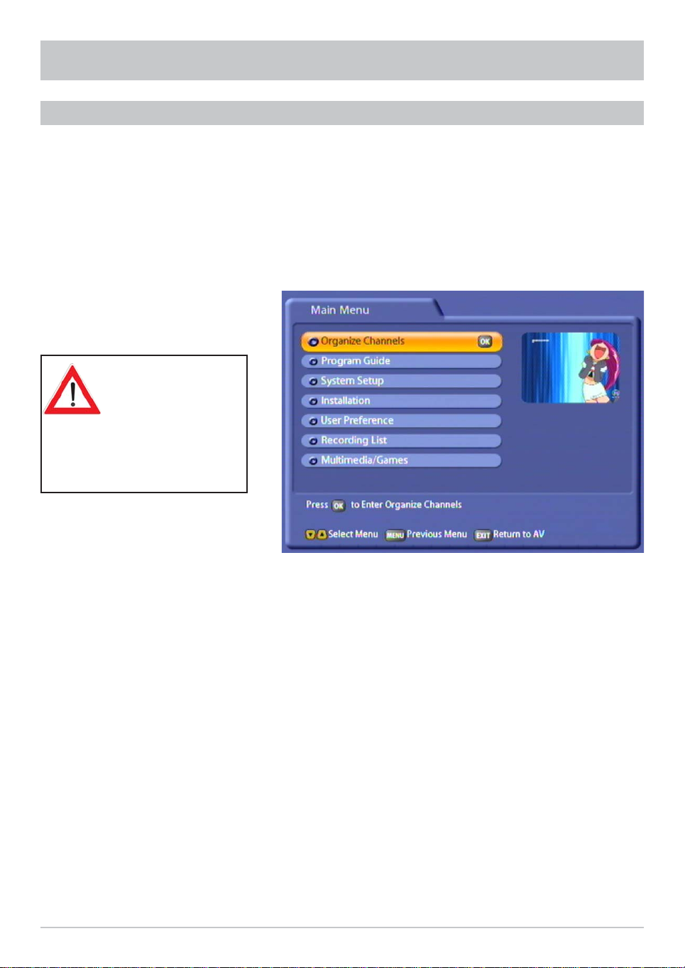
OPERATING INSTRUCTIONS
MENU CONCEPT
The structure of the menu concept is based on logical operating sequences. The programme showing
on the current selected channel always appears in the top right-hand corner of the screen.
You will fi nd detailed descriptions of the selected menu items in the relevant sections of the
operating manual!
Note: The selected menus, sub-menus and positions, as well as the parameters to be set, are
each highlighted in colour. The menus are self-explanatory.
Also pay attention
to the bars at the
bottom of the onscreen display!
These provide
information on what to do
next.
Press the button to call up the main menu and press the
Press the
menus.
The settings under the various options are made either by pressing the
the numeric pad. You can exit the main menu and sub-menus, and the various options, step-by-step
by pressing the
directly from one of the menus to the TV picture (the settings/changes you made are saved).
button to access the sub-menus. Press the
button (the settings/changes you made are saved). Press the button to return
buttons to call up the sub-menus.
buttons to select items within the sub-
buttons or by using
29
OPERATING INSTRUCTIONS
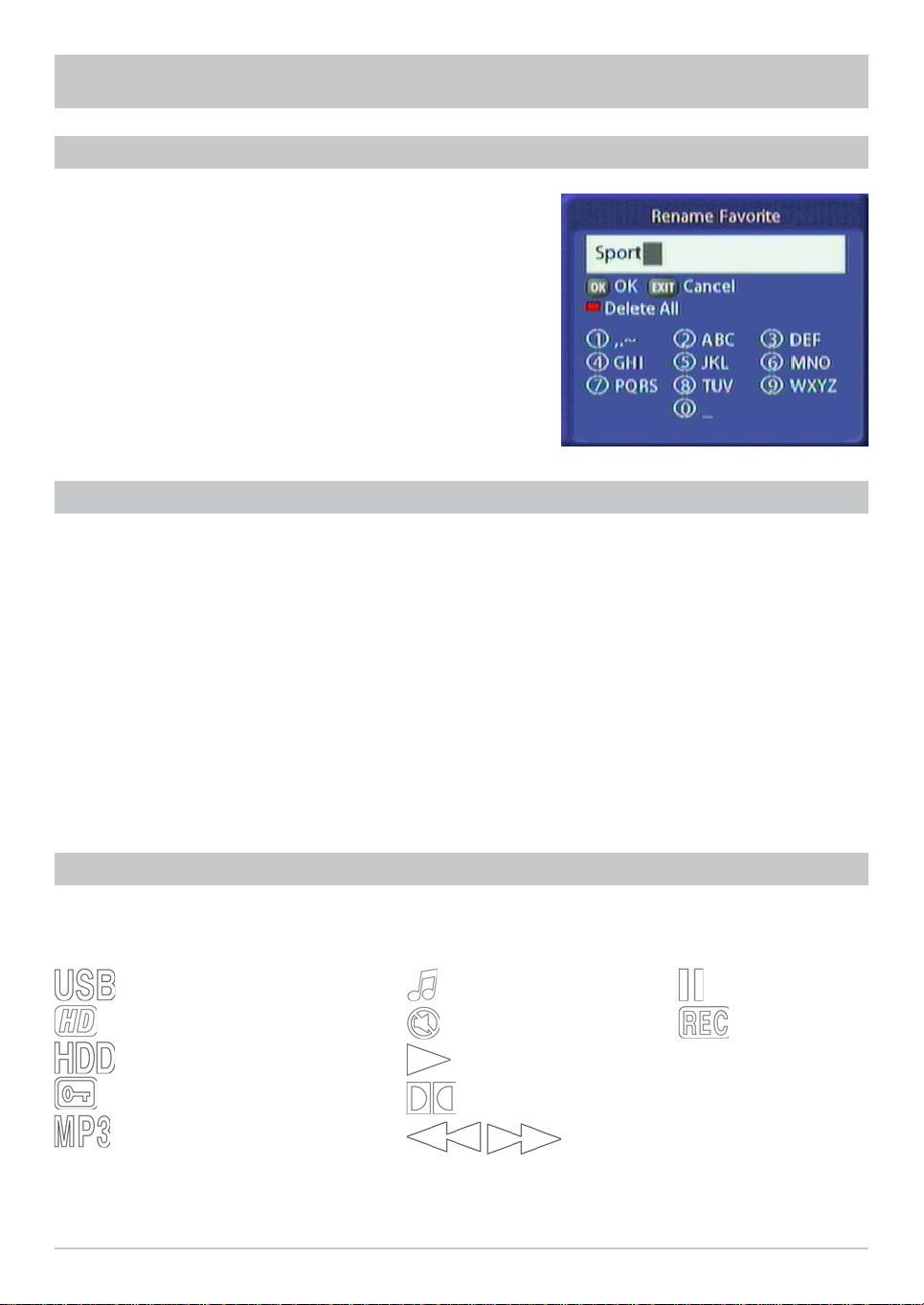
ALPHANUMERIC INPUTS
To enter channel, favourites and satellite names, use the key
pad that is displayed (see screenshot on the right). Select the
desired letters/symbols using the number keys on your remote
control. Press the
the
(red) button to delete the entire name. Once you have
selected all letters/symbols, press the
entry.
button to delete the last position or press
button to save your
LANGUAGE SELECTION - OSD
The language for the on-screen display is set as follows:
→
The languages available are German, English, Italian, French, Dutch, Polish, Spanish and Turkish.
You can now make the other possible settings:
- Subtitles language
- Audio language
- SI (Event) language
Settings are performed in the same way as the OSD language.
When you have made all the settings, press the
Press the
→ User Preferences → → Language Setup → →
button to exit the menu and save your settings.
button to return directly to the TV picture.
→ German
SYMBOL CODES FOR THE RECEIVER DISPLAY
Various symbols are occasionally shown in the receiver display above the normal display (channel name).
These are not shown permanently, they are shown only for specifi c functions, procedures or channel
features.
USB port for the application
Transmission is broadcast in HD
Hard disk in receiver active
Encrypted broadcast
MP3 playback
30
Radio operation
Mute
Play
Transmission is broadcast in Dolby Digital
Rewind/Wind on
Pause
Recording in
progress
Loading...