


 Loading...
Operating Manual
Satellite / TV / Radio
Test Receiver
MSK 24
Order No. 208 323
2

Preface
Dear Customer,
Kathrein-Werke KG has made every effort to ensure that this manual is correct and complete. No liability can be assumed for any mistakes that may still be contained in the manual or for any damage resulting from such mistakes.
This manual may not be copied in full or in part nor reproduced nor distributed in any other form without written permission from Kathrein KG.
We reserve the right to make alterations to this manual without prior notice. This applies in particular to alterations required for technical improvement.
All product names and trademarks used in this manual are the property of the relevant companies.
All rights reserved.
Validity of this manual
This manual is valid for MSK 24, order no. 208 323
As of August 2000
3

Contents
Preface ................................................................................................................................................. |
3 |
Validity of this manual....................................................................................................................... |
3 |
Contents................................................................................................................................................ |
4 |
General Notes....................................................................................................................................... |
6 |
Explanation of symbols ........................................................................................................................ |
6 |
Safety instructions ............................................................................................................................... |
6 |
How it operates..................................................................................................................................... |
7 |
Overview of functions........................................................................................................................... |
8 |
Block diagram of MSK 24...................................................................................................................... |
9 |
Technical Data ..................................................................................................................................... |
10 |
Operating and display elements .......................................................................................................... |
12 |
Display elements ................................................................................................................................ |
12 |
LC display ...................................................................................................................................... |
12 |
TFT colour screen ........................................................................................................................... |
12 |
Connections (right side) ...................................................................................................................... |
12 |
Overview of the keyboard commands.................................................................................................. |
13 |
Connections......................................................................................................................................... |
14 |
RF input socket .................................................................................................................................. |
14 |
External DC voltage supply ................................................................................................................. |
14 |
Scart output........................................................................................................................................ |
14 |
Starting up ........................................................................................................................................... |
15 |
Switching on the receiver .................................................................................................................... |
15 |
Switching off the receiver .................................................................................................................... |
15 |
Setup menu........................................................................................................................................ |
16 |
Factory settings .............................................................................................................................. |
16 |
Settings in the setup menu............................................................................................................... |
16 |
Calling up the setup menu ............................................................................................................ |
16 |
Mains and battery operation ................................................................................................................ |
17 |
Mains operation .............................................................................................................................. |
17 |
Battery operation............................................................................................................................. |
17 |
Sat measurement................................................................................................................................. |
18 |
Standard Switch-Over ......................................................................................................................... |
18 |
Frequency Display and Entering Frequency ......................................................................................... |
19 |
Overview of commands in Entering Frequency (SAT) ........................................................................ |
19 |
Level Measurement ............................................................................................................................ |
20 |
Level Overflow and Underflow.......................................................................................................... |
20 |
Tracking Satellites .............................................................................................................................. |
21 |
Tracking for Single Frequencies .......................................................................................................... |
22 |
Audio Carrier Frequency ..................................................................................................................... |
23 |
LNB Voltage and 22 kHz / 60 Hz Switch-Over....................................................................................... |
24 |
DiSEqC (Digital Satellite Equipment Control) ........................................................................................ |
26 |
Overview of commands in Framing Byte........................................................................................... |
27 |
Overview of commands in Address Byte........................................................................................... |
28 |
Overview of commands in Command Byte........................................................................................ |
29 |
Overview of commands in Data Byte................................................................................................ |
31 |
Simple Tone Burst DiSEqC ................................................................................................................. |
31 |
V-SEC (Vario-Satellite Equipment Control)........................................................................................... |
33 |
TV measurement.................................................................................................................................. |
34 |
Standard Switch-Over ......................................................................................................................... |
34 |
Channel Display and Entering Channel ................................................................................................ |
35 |
Frequency Display and Entering Frequency ......................................................................................... |
36 |
Level Measurement (TV)..................................................................................................................... |
37 |
Level Overflow and Underflow.......................................................................................................... |
37 |
Tracking for Single Frequencies .......................................................................................................... |
38 |
Audio Carrier Distance and Level......................................................................................................... |
39 |
Measuring the Audio Carrier Distance and Level of Nicam Audio Carriers:.......................................... |
40 |
NICAM – Measuring Audio Bit Error Rates ........................................................................................ |
40 |
Calling up Measuring Audio Bit Error Rates: ..................................................................................... |
40 |
4

Contents
FM measurement ................................................................................................................................. |
41 |
Frequency Display and Entering Frequency ......................................................................................... |
41 |
Level Measurement ............................................................................................................................ |
41 |
Level Overflow and Underflow.......................................................................................................... |
41 |
Tracking for Single Frequencies .......................................................................................................... |
42 |
Spectrum measurement....................................................................................................................... |
43 |
Sat Spectrum ..................................................................................................................................... |
43 |
TV Spectrum ...................................................................................................................................... |
43 |
FM Spectrum...................................................................................................................................... |
44 |
Maintenance ........................................................................................................................................ |
45 |
Changing the battery........................................................................................................................... |
45 |
Customer service............................................................................................................................ |
45 |
Technical Appendix............................................................................................................................. |
46 |
Signal-to-noise distance...................................................................................................................... |
46 |
DiSEqC commands for Kathrein matrices ............................................................................................. |
47 |
Command set for Kathrein matrix 9xx-series ..................................................................................... |
47 |
Command set for Kathrein matrix EXR 20......................................................................................... |
47 |
Command set for Kathrein matrix EXR 22......................................................................................... |
47 |
Channel tables ................................................................................................................................... |
48 |
Channel and frequency table for B/G standard (frequency in MHz)..................................................... |
48 |
Channel and frequency table for L standard (frequency in MHz)......................................................... |
49 |
Channel and frequency table for D/K standard (frequency in MHz)..................................................... |
50 |
Channel and frequency table for I standard (frequency in MHz).......................................................... |
51 |
Channel and frequency table for M1 Japan standard (frequency in MHz)............................................ |
52 |
Channel and frequency table for M/N standard (frequency in MHz)..................................................... |
53 |
Channel and frequency table for M/N standard (frequency in MHz)..................................................... |
54 |
Notes.................................................................................................................................................... |
55 |
5
General Notes
This manual has been written for persons with a basic knowledge of electrical engineering. At every step users who have already worked with measuring instruments can find the necessary commands in an overview. In addition, the following examples help to explain the operating steps.
Explanation of symbols
+
0
ë
Instructions shown with the warning symbol must be observed as otherwise the MSK 24 may be damaged or destroyed.
This symbol provides information on measuring functions and refers you to chapters containing further information on a subject.
This symbol is followed by an example of the measuring function just explained.
Here you will find an overview of the commands for the button combinations for the relevant measuring function.
[Button] |
The button to be pressed on the receiver. |
Safety instructions
Always observe VDE safety regulations!
Use only fuses that have the same cutout characteristics.
Observe the following upper limits when supplying signals:
• HF input: max. 120 dBìV (60dBmV)
•Do not apply a DC voltage >22 V to the HF socket
•Do not apply a low-frequency AC voltage to the HF socket The receiver is also live when disconnected.
Use only the power supply unit supplied to power the MSK 24.
A voltage of between 10 V and 20 V is available at the RF input socket depending on the programming. The source can supply up to 500 mA.
Parts supplied
1 plug-in power supply unit
1 BNC measuring cable
1 adapter for BNC socket to F socket
1 adapter for BNC socket to F plug
1 adapter for BNC socket to IEC socket
1 adapter for BNC socket to IEC plug
6

How it operates
The MSK 24 is designed as a universal portable test receiver for TV, SAT and FM radio for both battery and mains operation. A built-in lead battery with 2.8 Ah and a plug-in power unit for 230 V AC are included with the receiver.
A microcontroller is responsible for controlling the unit, scanning the keyboard and displaying frequency and level on the LC display. Receiving frequencies are indicated in MHz. Levels are measured with a peak or average value detector and indicated digitally in dBìV or dBmV. Correction values are determined when levels are calibrated for the MSK 24. They are stored in an EEPROM. Precise level measurements can thus be made.
There is a bar display on the front display to help find transmitters. In addition, there is an audio tracking signal to facilitate aligning of the antenna as the display does not have to be observed.
The audio section with its built-in loudspeaker is capable of processing and reproducing various audio frequency satellite signals, audio frequency TV signals complying with the B/G, D/K, I, M1 (Japan) and M/N standards, as well as FM audio. NICAM and AM audio reproduction (L standard) is also possible.
All currently known requirements are covered thanks to an LNB supply voltage of 10-20 V / max. 500 mA with steps of 0.1 V, the superimposition of 22 kHz / 60Hz and the facility of sending DiSEqC or V-SEC commands.
The built-in TFT colour screen allows pictures to be assessed locally.
7

Overview of functions
Function |
SAT mode |
TV mode |
FM mode |
|
|
|
|
Mains and battery operation |
* |
* |
* |
|
|
|
|
Level measurement by entering frequency |
* |
* |
* |
|
|
|
|
Level measurement by entering channel |
|
* |
|
|
|
|
|
Level-dependent acoustic signal |
* |
* |
* |
|
|
|
|
Loudspeaker for acoustic check |
* |
* |
* |
|
|
|
|
Reception of multiple standards (B/G, D/K, I, L, |
* |
* |
* |
Nicam, M/N, M1) |
|
|
|
Nicam audio reception and L standard |
|
|
|
|
|
|
|
Audio carrier setting |
* |
* |
|
|
|
|
|
Audio carrier measurement |
|
* |
|
|
|
|
|
Adjustable LNB voltage supply |
* |
|
|
LNB current measurement |
|
|
|
|
|
|
|
22 kHz / 60 Hz switch-over |
* |
|
|
|
|
|
|
DiSEqC, V-SEC |
* |
|
|
|
|
|
|
DVB measurement (QPSK, QAM) |
* |
* |
|
|
|
|
|
Scart output (video and audio) |
* |
* |
* (audio |
|
|
|
only ) |
|
|
|
|
Nicam audio, reception and bit error rate |
|
* |
|
measurement |
|
|
|
|
|
|
|
8

Block diagram of MSK 24
9

Technical Data
Power supply |
|
|
|
|
Mains operation |
|
230 VAC 50/60 Hz |
|
|
Battery operation |
|
12 V / 2.8 Ah lead battery |
|
|
Capacity |
|
|
|
|
|
|
|
||
Dimensions |
|
width 260 mm, height 90 (120) mm, depth 165 mm |
||
|
|
incl. accessories (plus bag) |
|
|
Weight |
|
4 kg (incl. bag) |
|
|
|
|
|
|
|
Safety standards |
|
CE label |
|
|
|
|
Protection class II |
|
|
|
|
VDE EN61010 |
|
|
Display |
|
TFT screen, alphanumerical LCD with 2 x 16 characters, |
||
|
|
bar display, background illumination |
||
|
|
|
|
|
Temperature range |
|
+5 °C to +45 °C |
|
|
Frequency range |
SAT |
920 MHz...2150 MHz |
|
|
|
TV |
45 MHz...867 MHz |
|
|
|
FM |
88 MHz...108 MHz (45 MHz...867 MHz) |
||
|
|
|
|
|
Channel allocation |
TV |
B standard |
7 MHz |
|
|
|
D/G/I/K standard |
8 MHz |
|
|
|
M/N/M1 standard |
6 MHz |
|
|
|
|
|
|
Frequency tuning |
SAT |
in 0.125 MHz steps |
|
|
|
TV |
in 50 kHz steps |
|
|
|
FM |
in 50 kHz steps |
|
|
|
|
|
|
|
Measuring errors |
SAT |
max. ±2 dB |
|
|
|
TV/FM |
max. ±2 dB |
|
|
|
|
|
|
|
RF input |
|
coaxial socket, BNC, 75Ù |
|
|
|
|
|
|
|
RF input separator |
|
0 – 60 dB in 4 dB steps |
|
|
|
|
|
|
|
Level measurement range |
|
30 dBìV – 120 dBìV |
|
|
|
|
|
|
|
Measuring bandwidth |
SAT |
6 MHz |
SAT DVB |
6 MHz |
|
TV |
250 kHz |
TV DVB |
6 MHz |
|
FM |
250 kHz |
|
|
|
|
|
|
|
Measuring detector |
SAT |
average value display |
|
|
|
TV |
peak value display |
|
|
|
FM |
average value display |
|
|
|
|
|
|
|
Return loss |
|
>6 dB |
|
|
|
|
|
|
|
FM threshold |
SAT |
<9 dB |
|
|
|
|
|
|
|
Audio IF bandwidth |
SAT |
230 kHz / 150 kHz |
|
|
|
TV |
230 kHz |
|
|
|
FM |
230 kHz |
|
|
|
|
|
|
|
Audio deemphasis |
SAT |
50 ìs |
|
|
|
TV/FM |
50 ìs |
|
|
|
|
|
|
|
10
Technical Data
Audio processing SAT |
FM audio processing |
5.0 MHz…8.99 MHz in steps of 10 kHz |
|
TV |
FM + Nicam in quasi parallel audio mode |
||
AM in parallel mode (only L standard) |
|||
TV |
B/G standard |
Audio carrier 1 = 5.5 MHz, Audio carrier 2 = 5.74 MHz |
|
|
D/K standard |
Audio carrier 1 = 6.5 MHz, Audio carrier 2 = 6.26 MHz |
|
|
I standard |
Audio carrier 1 = 6.0 MHz |
|
|
M/N standard |
Audio carrier 1 = 4.5 MHz, Audio carrier 2 = 4.72 MHz |
|
|
M1 standard |
Audio carrier 1 = 4.5 MHz |
|
|
L standard |
AM 6.5 MHz. Nicam = 5.85 MHz |
|
|
B/G standard |
Nicam = 5.85 MHz |
|
|
I standard |
Nicam = 6.552 MHz |
|
FM FM audio processing |
45 MHz...867 MHz |
||||
|
|
|
|
|
|
Audio carrier measurement |
TV |
B/G standard |
5.5 |
MHz, 5.74 MHz, 5.85 MHz |
|
|
|
D/K standard |
6.5 MHz, 6.26 MHz |
||
|
|
I standard |
|
6.0 MHz, 6.552 MHz |
|
|
|
L standard |
|
6.5 MHz, 5.85 MHz |
|
|
|
M/N standard |
4.5 MHz, 4.72 MHz |
||
|
|
M1 standard |
4.5 MHz |
||
|
|
|
|
|
|
Nicam decoder |
|
|
|
|
|
Audio carrier distance |
TV |
5.58 MHz with B/G, D/K, and L standards |
|||
|
|
6.552 MHz with I standard |
|
||
|
|
|
|
|
|
Nicam bit error rate |
TV |
0 - 4 x 10⁻² |
|
|
|
|
|
|
|||
LNB voltage supply |
SAT |
0, 10 V...20 V, max. 500 mA |
|||
|
|
|
|||
LNB control |
SAT |
22 kHz, 60 Hz, DISEqC, Simple DiSEqC, V-SEC |
|||
|
|
|
|
|
|
Scart output |
|
1 Vss / 75 Ohm |
|
|
|
11
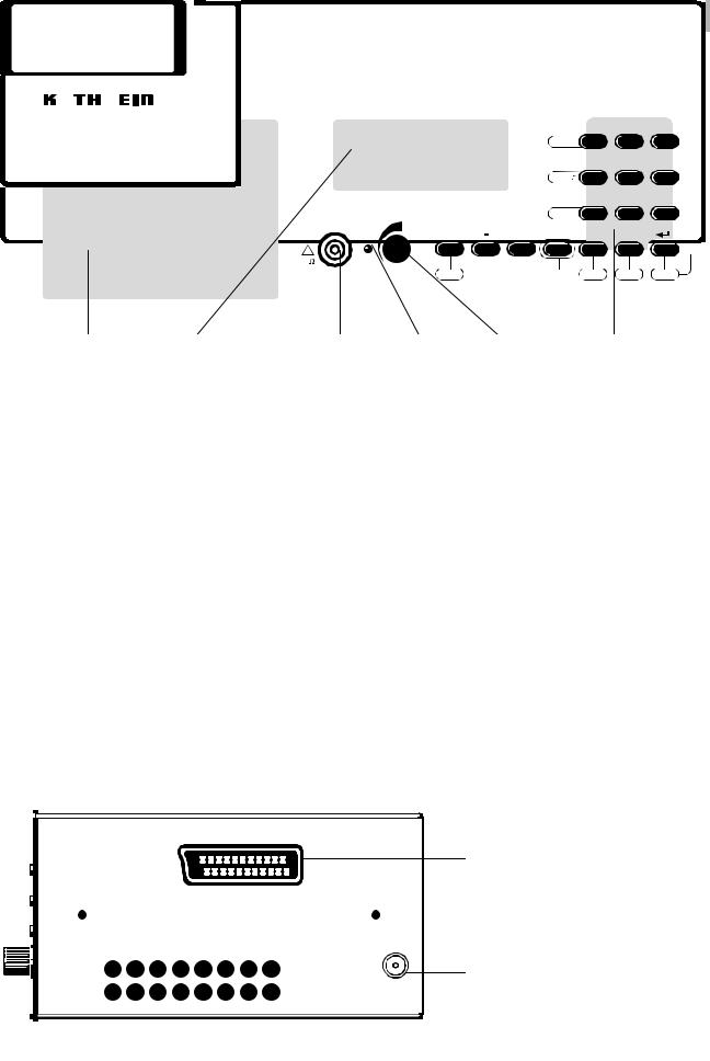
Operating and display elements
SAT . TV . FM TEST - RECEIVER
MSK 24
|
|
|
|
|
|
|
|
|
|
|
7 |
8 |
9 |
|
|
|
|
|
|
|
|
|
|
Sat-Ctrl |
|
|
|
LNB |
|||
|
|
|
|
|
|
|
|
|
|
|
4 |
5 |
6 |
|
|
|
|
|
|
|
|
|
|
|
|
|
|
|
|||
|
|
|
|
|
|
|
|
Level |
|
|
|
SC |
|||
|
|
|
|
|
|
|
|
|
|
|
1 |
2 |
3 |
|
|
|
|
|
|
|
|
|
|
|
|
|
|
|
|||
|
|
|
|
|
|
|
|
Ch-Frq |
14 |
25 |
36 |
Scan |
|||
RF |
LNB |
Sat/TV |
+ |
|
|
|
|
0 |
./S |
|
|
|
|||
|
|
|
|
|
|
|
|
|
|
|
|
|
|||
! |
|
|
|
|
|
|
|
|
|
|
|
|
|
MHz |
|
|
|
|
|
|
|
|
|
|
|
|
|
|
|||
7 5
Off
FM |
|
2ndF |
|
Spect |
|
Setup |
|
Std |
|
|
|
|
TFT colour screen |
LC display |
RF input socket |
LED Volume control Keyboard |
Display elements
LC display
|
|
FR: 954.0 MHz |
SAT |
LEV: 40.0 dBuV |
|
|
|
|
|
Depending on the mode the following information is shown in the LC display:
∙the set channel,
∙the set frequency,
∙the function called up,
∙the mode,
∙the level measured and
∙the measured values.
TFT colour screen
The colour screen has a diagonal of 4“ and a resolution of 238 x 480 pixels. The light intensity is 250 cd/m².
Connections (right side)
Scart connector without inputs
DC voltage supply – for supplied power supply unit only
12
Overview of the keyboard commands
Button |
|
|
Brief description of the function for |
|
|
||
|
SAT |
|
TV |
|
|
FM |
|
|
|
|
|
||||
|
|
|
|
|
|
|
|
SAT/TV |
Switch-over to TV reception |
|
Switch-over to SAT reception |
|
Switch-over to SAT reception |
||
|
|
|
|
|
|
|
|
- |
|
|
|
Decrease current values |
|
|
|
|
|
|
|
|
|
|
|
+ |
|
|
|
Increase current values |
|
|
|
|
|
|
|
|
|
|
|
0...9 |
|
|
|
Enter numbers |
|
|
|
|
|
|
|
|
|
|
|
|
Decimal point for |
|
∙ |
Decimal point for |
|
Decimal point for |
|
./S |
|
|
numerical entries |
|
|||
numerical entries |
|
|
|
numerical entries |
|||
|
|
∙ Call up special channel |
|
||||
|
|
|
|
|
|
||
|
|
|
|
|
|
|
|
ENTER |
|
|
|
Confirm numerical entries |
|
|
|
|
|
|
|
|
|
|
|
|
|
|
|
|
|
|
|
2ndF + |
|
|
Call up second command level |
|
|
||
button |
|
|
|
|
|||
|
|
|
|
|
|
|
|
|
|
|
|
||||
FM |
Switch-over to FM |
|
|
||||
|
|
|
|
|
|
|
|
Sat-Ctrl |
Call up the DISEqC/ |
|
|
|
|
|
|
V-SEC menu / LNB |
|
|
|
|
|
|
|
|
|
|
No function |
|
|
||
|
|
|
|
|
|
||
LNB |
LNB voltage menu and |
|
|
|
|
|
|
current measurement |
|
|
|
|
|
|
|
|
|
|
|
|
|
|
|
|
|
|
|
|
|
||
|
|
|
∙ Call up the frequency menu |
|
No function |
||
Ch-Freq |
No function |
|
∙ |
Switch-over from channel to |
|
||
|
|
|
|||||
|
|
|
|
frequency display and vice versa. |
|
||
|
|
|
|
|
|
|
|
Std |
DVB/analogue switch-over |
|
∙ |
DVB/analogue switch-over |
|
|
|
|
∙ Standard switch-over |
|
|
||||
|
|
|
|
|
|||
|
|
|
|
|
|
||
SC |
(Subcarrier) Audio carrier menu |
|
|
||||
|
|
|
|
||||
Scan |
Search for a satellite irrelevant of frequency |
|
|
||||
|
|
|
|||||
Level |
Switch on level-dependent acoustic signal with bar display |
||||||
|
|
|
|
|
|
|
|
Spect |
|
|
|
Spectrum analysis |
|
|
|
|
|
|
|
|
|
|
|
Setup |
|
|
|
Define receiver settings |
|
|
|
|
|
|
|
|
|
|
|
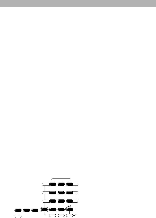
Keyboard of MSK 24:
Sat-Ctrl
See above for details
Level 
Ch-Frq
Sat/TV |
+ |
|||
|
|
|
|
|
7 |
8 |
9 |
4 |
5 |
6 |
1 |
2 |
3 |
41 |
25 |
63 |
0 |
./S |
|
LNB
SC
Scan
MHz
FM |
|
2ndF |
|
Spect |
|
Setup |
|
Std |
|
|
|
|
|||||
|
|
|
|
|
|
|
|
13
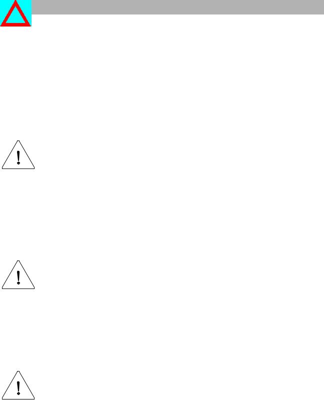
Connections
RF input socket
The signal received from the antenna system or the cable network is fed in here (BNC coaxial socket).
The remote powering voltage (for LNB) can be adjusted from 10 to 20 VDC and can be switched off. When the LNB voltage is switched on, the LED next to the RF input socket lights up.
Make sure that there is
∙no voltage level over 120 dBìV,
∙no positive DC voltage over 22 VDC,
∙no negative DC voltage and
∙no AC voltage.
on the RF input socket.
The input circuit can be seriously damaged if this warning is not heeded.
External DC voltage supply
The MSK 24 can be powered from the mains or its built-in battery. Voltage is supplied externally from the supplied power supply and recharging unit through the DC socket on the right side of the housing of the MSK 24.
Make sure that
∙only the supplied power supply unit is used,
∙the power supply unit is only connected to the receiver when it is to
be used to supply power. Otherwise the battery of the MSK 24 will be discharged!
Scart output
The visual and audio signals are available at the Scart socket on the right side of the MSK 24 for assessment on an external monitor.
No outputs are available!
Wrongly wired connectors may damage or destroy the receiver.
14

Starting up
Switching on the receiver
∙Connect the receiver with the battery charger/power supply unit to the mains supply.
∙Turn the on/off switch towards the right.
∙Set the desired volume.
Software V1.0
SN: 000222
ACCU [ ]
|
|
CH: .02. |
TV |
LEV: 48.5dBuV |
|
|
|
|
|
The LC display shows the software version and serial number of the MSK 24 for approx. 1 second.
Then the LC display indicates the capacity of the battery for approx. 3 seconds.
One segment is equivalent to approx. 20% of the total capacity (2.8 Ah).
Now apply the receiving signal from the receiver system into the RF input socket.
LC display:
∙channel
∙mode
∙level.
Use the [TV/SAT] button to select the required mode.
Switching off the receiver
Turn the on/off switch towards the left.
15

Starting up
Setup menu
The default setting (status of the MSK 24 when it is switched on) can be set in the setup menu.
Factory settings
Parameter |
Setting |
POWER ON |
TV |
LNB DC |
OFF |
LEVEL |
dBìV |
Low Level Mute |
ON |
Settings in the setup menu
Calling up the setup menu
POWER ON
TV=1 SAT=2 FM=3
1. Setup menu
|
|
LNB DC |
|
OFF=1 |
ON=2 |
|
|
|
|
2. Setup menu |
|
|
|
Level |
|
dBµV=1 |
dBmV=2 |
|
|
|
|
3. Setup menu |
|
|
|
CH: .07. |
TV |
LEV:____.__dBµV |
|
|
|
|
|
4. Setup menu |
|
|
|
LOW LEVEL MUTE |
|
OFF=1 |
ON=2 |
|
|
|
|
Default setting
Press the [2ndF] and [SETUP] buttons.
Press button [1], [2] or [3] to select the appropriate TV, SAT or FM mode. Press [ENTER] to retain the current setting.
The following request appears:
Press button [1] or [2] to switch the LNB voltage supply on or off. Press [ENTER] to retain the current setting.
In the next menu press button [1] or [2] to set the measuring unit in which the level should be displayed. Press [ENTER] to retain the current setting.
In the next menu you are requested to set the mute function by pressing button [1] or [2]. Select "ON" to mute the MSK 24 as long as the input signal on the RF input is below 30 dBìV.
Press [ENTER] to retain the current setting.
If you have not altered the factory default setting, the information shown on the left is displayed.
As soon as you have set the low level mute, setup menu 4 is exited automatically and the default setting displayed.
16

Starting up
Mains and battery operation
The MSK 24 can be powered from the mains or the built-in battery.
Mains operation
Use only the batttery charger/power supply unit supplied for mains operation. Connect the power supply unit to the voltage supply socket on the right side of the receiver.
If the receiver is not used for long periods, connect the receiver to the mains supply now and then (maintenance charging).
Make sure that the power supply unit is not connected to the receiver if it is not to be used to supply voltage as otherwise the battery will be discharged.
Battery operation
Battery operation is only possible if the battery is sufficiently charged.
Otherwise the MSK 24 cannot be switched on.
If the battery has been fully discharged, recharge it immediately as otherwise it may be damaged or destroyed.
Charging begins automatically as soon as the receiver has been connected to the mains supply. A protective circuit prevents the battery from being overcharged.
The capacity of the battery is displayed for approx. 3 seconds after the receiver has been switched on.
With a charged battery the maximum period of operation is approx. 2.5 hours for an LNB supply current of 150 mA.
17
Loading...