


 Loading...
User Manual
Antenna signal meter system
MSK 200/S2

PREFACE/IMPORTANT NOTES
Dear customer,
We kindly ask you to observe all instructions contained in this manual. The Kathrein-Werke KG has made every effort to ensure that the data and descriptions in this manual are accurate and complete.
We reserve the right to make changes to this manual without prior notice. This particularly applies to modi - cations required for technical improvement.
We appreciate your recommendations and suggestions for improvement.
Publications, copies and print-outs as well as electronic distribution of this manual in full or in part is only allowed with written authorisation from the Kathrein-Werke KG.
All product names and trademarks used in this manual are the property of the relevant companies.
VALIDITY OF THIS MANUAL
This manual is valid for the antenna signal meter system MSK 200/S2, Order No.: 21710024 and 21710025.
The following notes are relevant for the operation of the MSK 200 and should be adhered to under all circumstances.
GENERAL SAFETY INFORMATION
The MSK 200 has been developed and produced in consideration of the relevant harmonised guidelines, standards as well as further technical specifications. The product complies with the latest technology and ensures a high degree of safety. However, this degree of safety can only be achieved during operation if all required measures have been taken by the operator.
Electronic equipment is not domestic waste - in accordance with directive 2002/96/EC OF THE EUROPEAN PARLIAMENT AND THE COUNCIL dated 27th January 2003 on used electrical and electronic appliances, it must be disposed of properly.
At the end of its service life, take this unit for disposal to an appropriate official collection point.
Used batteries are hazardous waste!
Do not throw empty batteries into your domestic waste; take them to a collection point for used batteries!
2

CONTENT |
|
PREFACE/IMPORTANT NOTES ................................................................................................. |
2 |
GENERAL SAFETY INFORMATION .......................................................................................... |
2 |
CONTENT................................................................................................................................. |
3 |
SAFETY.................................................................................................................................... |
4 |
FEATURES/DELIVERY SCOPE .................................................................................................. |
6 |
DELIVERY SCOPE .................................................................................................................. |
6 |
OPERATION.............................................................................................................................. |
7 |
INITIAL START-UP ................................................................................................................... |
7 |
SETTING UP THE DEVICE....................................................................................................... |
7 |
SET-UP OPTIONS ................................................................................................................... |
7 |
USING THE DEVICE ON THE SHOULDER STRAP .................................................................... |
8 |
GENERAL OPERATION............................................................................................................. |
9 |
THE HELP FUNCTION ............................................................................................................. |
9 |
CHANGE THE HELP MENU’S DISPLAY LANGUAGE ...................................................................... |
9 |
KEYBOARD OPERATION......................................................................................................... |
9 |
TOUCHSCREEN OPERATION................................................................................................ |
10 |
OPERATION............................................................................................................................ |
13 |
CHOICE OF THE SIGNAL SOURCE AND MEASUREMENT ...................................................... |
13 |
CHOICE OF THE SIGNAL SOURCE.......................................................................................... |
13 |
CHOOSING THE CHANNEL TO BE MEASURED ......................................................................... |
14 |
SELECTING THE DESIRED MEASUREMENT............................................................................. |
14 |
FUNCTION OVERVIEW............................................................................................................ |
16 |
TECHNICAL APPENDIX........................................................................................................... |
18 |
DESIGN ................................................................................................................................ |
18 |
FUNCTIONS.......................................................................................................................... |
18 |
SERVICE ................................................................................................................................ |
22 |
DEVICE CALIBRATION .......................................................................................................... |
22 |
EXTERIOR CLEANING .......................................................................................................... |
22 |
INTERIOR CLEANING............................................................................................................ |
22 |
FUNCTION TEST................................................................................................................... |
22 |
MEASURING EQUIPMENT REQUIRED................................................................................... |
22 |
STORAGE............................................................................................................................. |
22 |
SERVICE ................................................................................................................................ |
23 |
MAIN SERVICES ................................................................................................................... |
23 |
SERVICE .............................................................................................................................. |
23 |
3
SAFETY
This device was built and tested in accordance with the enclosed EU certificate of conformity and left the factory in a condition fullfilling all requisite safety regulations. To ensure that this condition is maintained and to ensure hazard-free operation, the user must observe all instructions, warnings and warning notes.
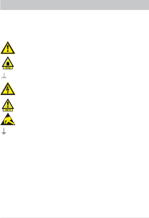
Symbols used on Kathrein devices and in manuals:
Follow operating instructions
Information on the weight of devices with a mass > 18 kg
Earth conductor connection. Ground connection point caution!
Hazardous voltage on physical contact
Warning hot surfaces
Electrostatic sensitive components requiring special handling
Attention Earthing!
1.The device is only allowed to be operated in the operational status and in systems as stated by the manufacturer (attention is to be paid to adequate ventilation). The following applies: IP protection class 2X, degree of soiling 2, overvoltage category 2, only for use indoors, operation at up to 2000 m above sea level. Outdoor use is only permissible if the measuring instrument is protected from rain and humidity. The device is only allowed to be operated on supply grids that are protected with fuses with a maximum rating of 16 A. If not otherwise stated in the data sheet, a tolerance of ± 10 % applies to the nominal mains voltage and a tolerance of ± 5 % to the nominal mains frequency.
2.In case of measurements in circuits with voltages Ueff > 30 V, precautions must be taken using suitable measures to ensure that any hazard is excluded (e.g. suitable measuring equipment, fuse protection, current limiting, isolation, insulation, etc.).
3.If a device is installed in a fixed position, the connection between the on-site earth conductor connection and the device‘s earth conductor is to be made before any other connections are made. Installation and connection should only be performed by trained electricians.
4.If devices in a fixed installation do not have a fuse, circuit breaker or similar protective device, the supply circuit must be fused so that device and user are adequately protected.
4

SAFETY
5.Prior to switching on the device, ensure that the nominal mains voltage set on the device and the nominal mains voltage of the supply match. If it is necessary to change the voltage setting, it may also be necessary to change the respective mains fuse for the device.
6.In case of devices in protection class I with a flexible mains cable and mains plug, operation is only allowed using wall socket outlets with an earth contact and connected earth conductor.
7.Any intentional interruption of the earth conductor, either in the supply cable or in the device itself is not allowed and can result in a dangerous voltage being laid directly on the device. If extension cables or power strips are used, it is imperative that these are checked that they comply with safety regulations at regular intervals.
8.The device is not equipped with a mains switch allowing mains disconnection. Therefore, the plug on the connection cable is to be considered a mains power disconnection element. It is to be ensured the mains plug is easily accessible at all times (length of the connecting cable approx. 2 m). Function switches or electronic switches are not suitable for mains isolation. If devices without a mains switch are integrated into racks or systems, the mains power disconnection element is to be moved to system level (system level switchoff).
9.During all work, the local and national health and safety regulations are to be followed. Prior to work on the device or opening the device, it is to be isolated from the mains supply. Calibration, replacement of parts, maintenance and repair should only be undertaken by trained electricians. If safety-related parts (e.g. mains switches, mains transformers or fuses) are replaced, these must only be replaced with original parts. A safety test is to be performed after any replacement of safety-related parts (visual inspection, earth conductor test, insulation resistance, leakage current measurement, function test).
10.In case of connections to information technology devices, it is to be ensured that these devices comply with IEC950/EN60950.
11.Lithium batteries are not to be subjected to high temperatures or fire. Keep the batteries away from children. If the battery is incorrectly replaced, there is a risk of explosion. Replace the batteries only with the original type (see list of spare parts). Lithium batteries are hazardous waste. Only dispose of them in containers provided for this purpose. Do not short-circuit batteries.
12.Devices that are returned or sent in for repair must be packed in the original packaging or in packaging that provides protection against electrostatic charging and discharging as well as against mechanical damage.
13.Discharges via connectors can damage the device. The device is to be protected against electrostatic discharge in use and operation.
14.Clean the exterior of the device with a soft, fluff-free duster. Under no circumstances use solvents such as thinners, acetone or similar, as otherwise the front panel markings or plastic parts may be damaged.
15.Additional safety instructions in this manual are also to be followed.
5

FEATURES/DELIVERY SCOPE
The MSK 200 is a compact state-of-the-art signal meter which leaves nothing to be desired when you are checking antenna and cable systems or even professional head-end systems. It can be used either in a lab or for the monitoring of remote-controlled head-end systems, or for final measurements on antenna and distribution systems.
DELIVERY SCOPE
MSK 200/S2, Order no. 21710024 (75 Ω):
-1 antenna signal meter system MSK 200
-1 AC power supply unit
-Transport case
-1 measurement cable - BNC plug - BNC socket
-1 adaptor - 1.6/5.6 plug - BNC socket
-1 adaptor - BNC socket - F socket
-1 adaptor - BNC socket - F connector
-1 adaptor - BNC socket - IEC socket
-1 adaptor - BNC socket - IEC plug
-1 shoulder strap
-1 fuse T 8.0 A
MSK 200/S2, Order no. 21710025 (50 Ω):
-1 antenna signal meter system MSK 200/50
-1 AC power supply unit
-Transport case
-1 shoulder strap
-1 fuse T 8.0 A
6
OPERATION
INITIAL START-UP
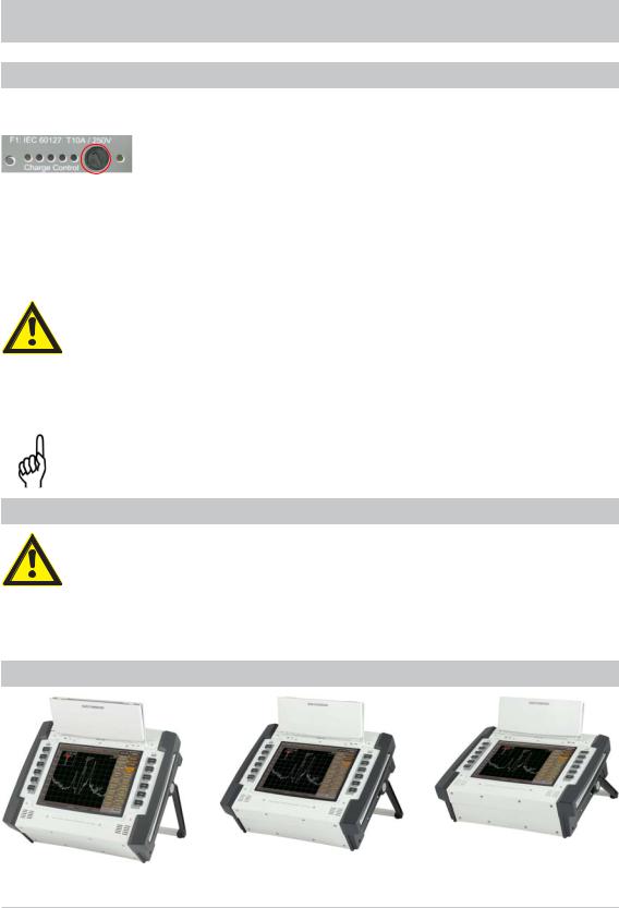
Prior to operating for the first time, please take the T 8.0 A fuse out of the packaging and fit it into the provided fuse holder.
After insertion of the protector, the device muss be operated or charged on the power supply unit for approximately two hours. Subsequently, the device must be completely discharged during battery-powered operation (until the device switches off by itself). Battery charge level can only be correctly displayed if the device has been fully charged and then fully discharged.
The fuse prevents the device being switched on unintentionally during transport.
Caution!
Please remove this fuse again before shipping the device!
Remove the AC power supply unit (100V ... 250V) supplied from the packaging and connect the device to the mains using the power supply. The Li ion rechargeable battery in the device will now be charged. The green light emitting diode indicates use of an external power source. You can check the charge state of the rechargeable battery by pressing the “Test“ key.
Caution!
See also “Charging indicator” and “DC supply socket” in the section “Interfaces”
SETTING UP THE DEVICE
When setting up the device pay attention to adequate ventilation!
To avoid a build-up of heat, the openings for the fan and the ventilation holes must always be kept clear. Set up the device as shown in the figure.
SET-UP OPTIONS
7
OPERATION
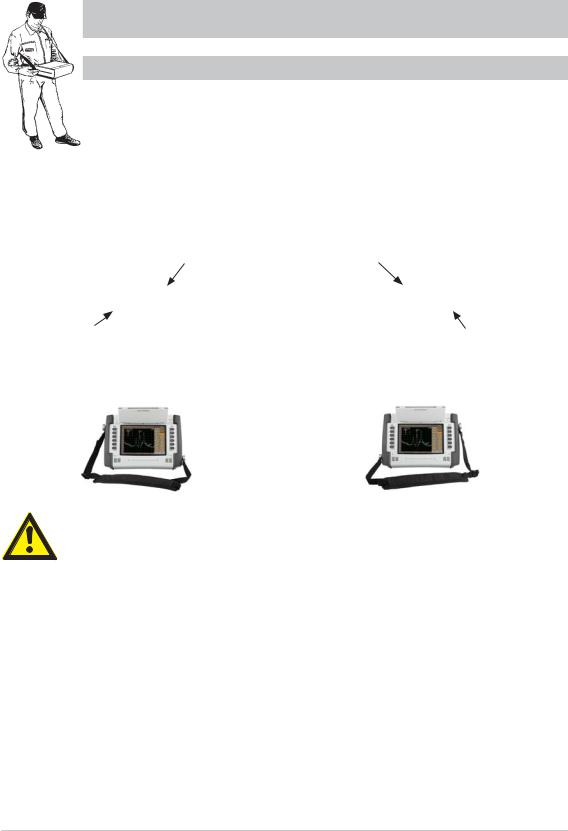
USING THE DEVICE ON THE SHOULDER STRAP
When the device is used on the strap, also provide for adequate ventilation!
To avoid a build up of heat, the openings for the fan and the ventilation holes must always be clear.
For right-handed users |
For left-handed users |
Pass the shoulder strap over your right shoulder! |
Pass the shoulder strap over your left shoulder! |
Strap fastener far |
Strap fastener far |
from body |
from body |
Strap fastener |
Strap fastener |
near body |
near body |
|
|
|
|
Warning!
To avoid neck injuries, do not just hang the measuring instrument around your neck, but observe the instructions above.
You can move the softkeys from right to left by activating the following sequence of keys “EXTEND“, “SETUP“, “LOOK´N FEEL”, “BAR LAYOUT”!
8
Loading...