


 Loading...
OUTDOOR HOUSING
WB-1540U WB-1550U
INSTRUCTIONS
(B) WB-1550U only
ITALIANO ESPAÑOL FRANÇAIS DEUTSCH ENGLISH
For Customer Use:
Enter below the Serial No. which is located on the body.
Retain this information for future reference.
Model No. |
WB-1540U/WB-1550U |
|
|
Serial No.
LST0267-001C

These are general IMPORTANT SAFEGUARDS and certain items may not apply to all appliances.
IMPORTANT SAFEGUARDS
1.Read all of these instructions.
2.Save these instructions for later use.
3.All warnings on the product and in the operating instructions should be adhered to.
4.Unplug this appliance system from the wall outlet before cleaning.Do not use liquid cleaners or aerosol cleaners.Use a damp cloth for cleaning.
5.Do not use attachments not recommended by the appliance manufacturer as they may cause hazards.
6.Do not use this appliance near water - for example, near a bathtub, washbowl, kitchen sink, or laundry tub, in a wet basement, or near a swimming pool, etc.
7. Do not place this appliance on an unstable cart, stand, or table. The appliance may fall, causing serious injury to a child or adult, and serious damage to the appliance may fall, causing serious injury to a child or adult, and serious damage to the appliance.
Use only with a cart or stand recommended by the manufacturer, or sold with the appliance. Wall or shelf mounting should follow the manufacturer’s instructions, and should use a mounting kit approved by the manufacturer.
An appliance and cart combination should be moved with care. Quick stops, excessive force, and uneven surfaces may cause the appliance and cart combination to overturn.
8. Slots and openings in the cabinet and the back or bottom are provided for ventilation, and to insure reliable operation of the appliance and to protect it from overheating,these openings must not be blocked or covered. The openings
should never be blocked by placing the appliance on a bed, sofa, rug, or other similar surface. This appliance should
never be placed near or over a radiator or heat register. This appliance should not be placed in a built-in installation such as a bookcase unless proper ventilation is provided.
9.This appliance should be operated only from the type of power source indicated on the marking label. If you are not sure of the type of power supplied to your home, consult your dealer or local power company. For appliance designed to operate from battery power, refer to the operating instructions.
10.For added protection for this product during a lightning storm, or when it is left unattended and unused for long periods of time, unplug it from the wall outlet and disconnect the antenna or cable system. This will prevent damage to the product due to lightning and power-line surges.
11.Do not allow anything to rest on the power cord. Do not locate this appliance where the cord will be abused by persons walking on it.
12.Follow all warnings and instructions marked on the appliance.
13.Do not overload wall outlets and extension cords as this can result in fire or electric shock.
14.Never push objects of any kind into his appliance through cabinet slots as they mat touch dangerous voltage points or short out parts that could result in a fire or electric shock. Never spill liquid of any kind on the appliance.
15.Do not attempt to service this appliance yourself as opening or removing covers may expose you to dangerous voltage or other hazards. Refer all servicing to qualified service personnel.
16.Unplug his appliance from the wall outlet and refer servicing to qualified service personnel under following conditions:
a.When the power cord or plug is damaged or frayed.
b.If liquid has been spilled into the appliance.
c.If the appliance has been exposed to rain or water.
d.If the appliance does not operate normally by following the operating instructions. Adjust only those controls that are covered by the operating instructions as improper adjustment of other controls may result in damage and will often require extensive work by a qualified technician to restore the appliance to normal operation.
e.If the appliance has been dropped or the cabinet has been damaged.
f.When the appliance exhibits a distinct change in performance - this indicates a need for service.
17.When replacement parts are required, be sure the service technician has used replacement parts specified by the manufacturer that have the same characteristics as the original part. Unauthorized substitutions may result in fire, electric shock, or other hazards.
18.Upon completion of any service or repairs to this appliance, ask the service technician to perform routine safety checks to determine that the appliance is in safe operating condition.
2
For USA and CANADA
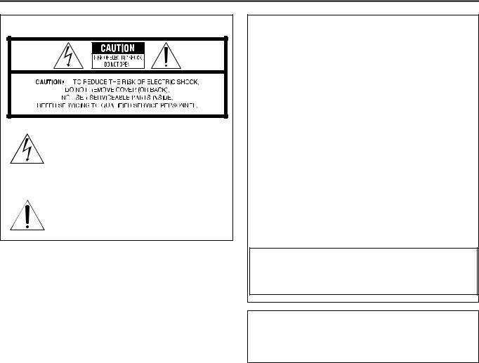
The lightning flash with arrowhead symbol, within an equilateral triangle, is intended to alert the user to the presence of uninsulated “dangerous voltage” within the product’s enclosure that may be of sufficient magnitude to constitute a risk of electric shock to persons.
The exclamation point within an equilateral triangle is intended to alert the user to the presence of important operating and maintenance (servicing) instructions in the literature accompanying the appliance.
I
INFORMATION FOR USA
INFORMATION
This equipment has been tested and found to comply with the limits for a Class B digital device, pursuant to Part 15 of the FCC Rules.
These limits are designed to provide reasonable protection against harmful interference in a residential installation. This equipment generates, uses, and can radiate radio frequency energy and, if not installed and used in accordance with the instructions, may cause harmful interference to radio communications. However, there is no guarantee that interference will not occur in a particular installation.
If this equipment does cause harmful interference to radio or television reception, which can be determined by turning the equipment off and on, the user is encouraged to try to correct the interference by one or more of the following measures:
●Reorient or relocate the receiving antenna.
●Increase the separation between the equipment and receiver.
●Connect the equipment into an outlet on a circuit different from that to which the receiver is connected.
●Consult the dealer or an experienced radio/TV technician for help.
CAUTION
CHANGES OR MODIFICATIONS NOT APPROVED BY JVC COULD VOID USER'S AUTHORITY TO OPERATE THE EQUIPMENT.
THIS DEVICE COMPLIES WITH PART 15 OF THE FCC RULES.
OPERATION IS SUBJECT TO THE FOLLOWING TWO CONDITIONS: (1) THIS DEVICE MAY NOT CAUSE HARMFUL INTERFERENCE, AND (2) THIS DEVICE MUST ACCEPT ANY INTERFERENCE RECEIVED, INCLUDING INTERFERENCE THAT MAY CAUSE UNDESIRED OPERATION.
INFORMATION (FOR CANADA) RENSEIGNEMENT (POUR LE CANADA)
This Class [B] digital apparatus complies with Canadian ICES-003. Cet appareil numérique de la classe [B] est conforme à la norme NMB-003 du Canada.
Due to design modification, data given in this instruction book are subject to possible change without prior notice.
3

Getting Started
Thank you for purchasing this product. (These instructions are for WB-1540U/ WB-1550U)
Before beginning to operate this unit, please read the instruction manual careully in order to make sure that the best possible performance is obtained.
The compatible cameras for each housing are as follows: ● WB-1540U: TK-C625U/E,VN-C625U
● WB-1550U: TK-C676E,TK-C655E,VN-C655U
Table of Contents
Getting Started |
|
Installation and Connection (WB-1550U) |
|
Table of Contents ................................................................... |
4 |
Disassembling the Housing ................................................. |
10 |
Operating Precautions ........................................................... |
4 |
Procedures Before Mounting the Camera ........................... |
10 |
System Example .................................................................... |
5 |
Mounting the Camera ......................................................... |
11 |
VN-C625U and VN-C655U Systems ................................. |
5 |
TK-C655E and TK-C676E .............................................. |
11 |
TK-C625U/E, TK-C655E and TK-C676E Systems ............ |
5 |
VN-C655U ....................................................................... |
12 |
Installation and Connection (WB-1540U) |
|
Assembling the Housing ...................................................... |
13 |
Disassembling the Housing .................................................... |
6 |
Mounting the Housing to the wall ........................................ |
13 |
Mounting the Camera ............................................................ |
6 |
Others |
|
TK-C625U/E ...................................................................... |
6 |
Specifications ...................................................................... |
15 |
VN-C625U ......................................................................... |
7 |
WB-1540U ...................................................................... |
15 |
Assembling the Housing ........................................................ |
8 |
WB-1550U ...................................................................... |
15 |
Mounting the Housing to the wall ........................................... |
8 |
|
|
Operating Precautions
Depending on the installation environment of this unit, the life span of the attached camera may decrease significantly. Give close attention to the installation location (especially if used continuously under high temperature or in locations constantly exposed to direct sunlight).
As the interior of this unit will heat up, be sure to use San Disk (industrial) if loading the CF card to VN-C625U.
This unit may stop functioning properly due to natural hazards as it is to be installed outdoors. To take photographs properly, be sure to perform daily checks.
Do not install this unit in locations with sharp temperature changes, such as near air-con compressors or exhaustpipes. Condensation may occur inside the attached combination camera.
To save energy, switch off the system when not in use.
For safety reasons special techniques are necessary for installation. Consult your dealer regarding installation, and ensure that it is carried out by a specialist.
Be sure to mount the safety wire for safety purposes. If it falls, it may cause injury or accidents.
Taking vibrations, mass and wind force into account, ensure to mount in a location with sufficient strength using solid anchor bolts. If reinforced or spiral nuts are not tightened enough, picture blurring may occur on the monitor screen due to vibration, and in the worst case there is a danger of falling.
Use at the voltage indicated. A voltage other than that displayed may result in fire or electric shocks.
This unit supports lightning conduction to the connection cable to some extent, but not fully. At installation locations where there may be a lightning hazard, be sure to add an arrester to the connection cable or take other precautions.
Do not dangle, shake, or hook objects. If too much load is placed on top, it may fall and cause injury or accidents.
If a ball or bird hits this unit, bringing about some sort of trouble, consult your dealer or the nearest Victor service center.
Do not modify this unit yourself. Accidents may result.
Do not install in locations where there may be vibrations or impact. If it falls, it may cause injury or accidents.
Regularly check for the deterioration of attaching parts and the loosening of the screws caused by vibrations. If it falls, it may cause injury or accidents.
Do not install in locations where radiation, X-rays, or corrosive gases are emitted. Doing so may cause the camera to malfunction.
Keep all packaging out of the reach of children. If used for play, it may cause injury or suffocation.
This installation should be made by a qualified service person and should conform to all local codes and the National Electrical Code , ANSI/NFPA 70.
4

System Example
VN-C625U and VN-C655U Systems
WB-1540U / WB-1550U |
Power Cable (DC 12V) |
Power Cable |
|
|
Not in use on this system. (T1) |
(AC 24V) |
AC 24 V Power Supply |
|
|
|
|
T1 |
|
|
Coaxial Cable |
|
|
|
|
|
|
|
Monitor |
|
WB-1540U / WB-1550 U(Main Board) |
|
Alarm Cable |
|
|
|
|
INPUT |
LED1 |
Alarm Device |
|
|
|
|
To TB1 |
~ |
|
|
AC24V |
|
|
|
|
|
LAN Cable |
|
(Connected) |
TB1 |
|
LAN |
|
|
||
|
TO CAMERA |
PC |
|
|
|
|
Power Indicator |
|
|
|
Red light turns on during power supply. |
VN-C625U/655U |
Fuse T |
|
|
Supplied Converter |
To [VIDEO OUT] Terminal |
Unit |
To [ALARM IN/OUT] Terminal |
|
|
To [POWER INPUT DC 18 V] |
To [10 BASE-T/100 BASE-TX] Terminal |
Terminal (VN-C655U) |
Ceiling Mount of Network Camera |
To [POWER INPUT DC 12 V] |
|
Terminal (VN-C625U) |
|
CAUTION:
T1: Not in use on this system. Ensure to bind both ends of cables that are not in use with insulating tape.
T2: Power will not be supplied to this unit and the installed camera when the fuse on the main board burns out. When this occurs, please consult your nearby JVC dealer as exchange of fuse according to the rating (125 V - 5 A) will be required.
TK-C625U/E, TK-C655E and TK-C676E Systems
WB-1540U / WB-1550U |
Power Cable (DC 12 V) |
|
Not in use on this system. (T1)
LAN Cable |
Power Cable (AC 24 V) |
|
|
To Insulated AC 24 V Power Supply |
|
T1 |
Coaxial Cable |
|
VIDEO INPUT |
||
|
||
|
Communication Cable |
|
|
TO CAMERA |
WB-1540U / WB-1550U (Main Board)
|
INPUT |
LED1 |
To TB1 |
~ |
|
AC24V |
|
|
|
|
|
(Connected) |
TB1 |
|
|
|
|
|
TO CAMERA |
|
Fuse T
To [VIDEO OUT/TO CCU] Terminal
|
|
|
REMOTE CONTROL UNIT RM-P2580 |
|||
SETUP |
|
CAMERA |
POSITION |
|
|
|
|
POWER |
|
|
|
|
|
MENU |
SET |
ALARM |
AUTO |
F-1 |
F-2 |
F-3 |
|
|
KEY LOCK |
|
|
|
|
|
LENS |
|
|
CAMERA/POSITION |
PAN/TILT |
||
|
SPEED |
|
1 |
2 |
3 |
CAMERA |
POSI- |
|
|
|
TION |
||||
CLOSE IRIS |
OPEN |
4 |
5 |
6 |
OPTION1 |
OPTION2 |
|
NEAR |
FOCUS |
FAR |
7 |
8 |
9 |
AUTO |
AUTO |
AF |
PAN |
PATROL |
|||||
WIDE |
ZOOM |
TELE |
CLEAR |
0 |
ENTER |
|
|
/HOME |
|
|
|||||
RM-P2580U/E
Power Indicator
Red light turns on during power supply.
To [POWER INPUT |
To [CONTROL/ALARM IN, OUT] Terminal |
AC 24 V ~] Terminal |
|
|
Ceiling Mount of Combination Camera |
CAUTION:
●Ensure to turn of the power of devices in use before connecting.
●Refer to the instruction manual for the combination camera that is supplied with this unit as well during connection and installation. T1: Not in use on this system. Ensure to bind both ends of cables that are not in use with insulating tape.
T2: Power will not be supplied to this unit and the installed camera when the fuse on the main board burns out. When this occurs, please consult your nearby JVC dealer as exchange of fuse according to the rating (125 V - 5 A) will be required.
5
Loading...