


DVD DIGITAL CINEMA SYSTEM
TH-M45
Consists of XV-THM45, SP-PWM45, SP-THM45C, SP-THM45F and SP-THM45S
INSTRUCTIONS
LVT1024-003B [B]

Warnings, Cautions and Others
IMPORTANT for the U.K.
DO NOT cut off the mains plug from this equipment. If the plug fitted is not suitable for the power points in your home or the cable is too short to reach a power point, then obtain an appropriate safety approved extension lead or consult your dealer.
BE SURE to replace the fuse only with an identical approved type, as originally fitted.
If nonetheless the mains plug is cut off ensure to remove the fuse and dispose of the plug immediately, to avoid a possible shock hazard by inadvertent connection to the mains supply.
If this product is not supplied fitted with a mains plug then follow the instructions given below:
IMPORTANT.
DO NOT make any connection to the terminal which is marked with the letter E or by the safety earth symbol or coloured green or green-and- yellow.
The wires in the mains lead on this product are coloured in accordance with the following code:
Blue: Neutral
Brown: Live
As these colours may not correspond with the coloured markings identifying the terminals in your plug proceed as follows:
The wire which is coloured blue must be connected to the terminal which is marked with the letter N or coloured black.
The wire which is coloured brown must be connected to the terminal which is marked with the letter L or coloured red.
IF IN DOUBT - CONSULT A COMPETENT ELECTRICIAN.
CAUTION
To reduce the risk of electrical shocks, fire, etc.:
1.Do not remove screws, covers or cabinet.
2.Do not expose this appliance to rain or moisture.
CAUTION — F button! (XV-THM45)
Disconnect the mains plug to shut the power off completely (the STANDBY lamp goes off).
The Fbutton in any position does not disconnect the mains line.
•When the system is on standby, the STANDBY lamp lights red.
•When the system is turned on, the STANDBY lamp goes off. The power can be remote controlled.
CAUTION (SP-PWM45)
The power supply to the subwoofer is linked to the center unit. The POWER ON lamp on the subwoofer lights green when the power is turned on.
CAUTION
•Do not block the ventilation openings or holes.
(If the ventilation openings or holes are blocked by a newspaper or cloth, etc., the heat may not be able to get out.)
•Do not place any naked flame sources, such as lighted candles, on the apparatus.
•When discarding batteries, environmental problems must be considered and local rules or laws governing the disposal of these batteries must be followed strictly.
•Do not expose this apparatus to rain, moisture, dripping or splashing and that no objects filled with liquids, such as vases, shall be placed on the apparatus.
G-1
Warnings, Cautions and Others
IMPORTANT FOR LASER PRODUCTS
REPRODUCTION OF LABELS
A CLASSIFICATION LABEL, PLACED ON EXTERIOR SURFACE
B WARNING LABEL, PLACED INSIDE THE UNIT
1.CLASS 1 LASER PRODUCT
2.CAUTION: Visible and invisible laser radiation when open and interlock failed or defeated. Avoid direct exposure to beam.
3.CAUTION: Do not open the top cover. There are no user serviceable parts inside the Unit; leave all servicing to qualified service personnel.
G-2
Warnings, Cautions and Others
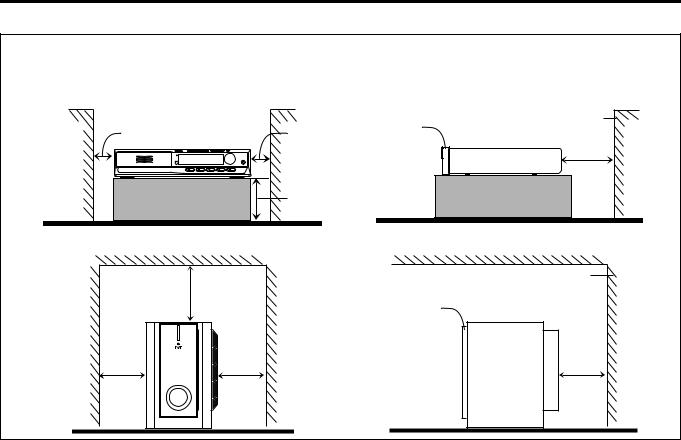
Caution: Proper Ventilation
To avoid risk of electric shock and fire and to protect from damage, place the apparatus on a level surface. The minimal clearances are shown below:
No obstructions
Wall or |
1 cm |
XV-THM45 |
1 cm |
obstructions |
|
|
|
|
|
|
|
|
|
|
10 cm |
Wall or |
|
obstructions |
20 cm |
|
|
SP-PWM45 |
|
15 cm |
15 cm |
Wall or obstructions |
Front |
XV-THM45 |
10 cm |
No obstructions |
Wall or obstructions
Front SP-PWM45
No obstructions
15 cm
G-3

Warnings, Cautions and Others
SAFETY INSTRUCTIONS
“SOME DOS AND DON’TS ON THE SAFE USE OF EQUIPMENT”
This equipment has been designed and manufactured to meet international safety standards but, like any electrical equipment, care must be taken if you are to obtain the best results and safety is to be assured.
Do read the operating instructions before you attempt to use the equipment.
Do ensure that all electrical connections (including the mains plug, extension leads and interconnections between pieces of equipment) are properly made and in accordance with the manufacturer’s instructions. Switch off and withdraw the mains plug when making or changing connections.
Do consult your dealer if you are ever in doubt about the installation, operation or safety of your equipment.
Do be careful with glass panels or doors on equipment.
DON’T continue to operate the equipment if you are in any doubt about it working normally, or if it is damaged in any way — switch off, withdraw the mains plug and consult your dealer.
DON’T remove any fixed cover as this may expose dangerous voltages.
DON’T leave equipment switched on when it is unattended unless it is specifically stated that it is designed for unattended operation or has a standby mode.
Switch off using the switch on the equipment and make sure that your family know how to do this. Special arrangements may need to be made for infirm or handicapped people.
DON’T use equipment such as personal stereos or radios so that you are distracted from the requirements of traffic safety. It is illegal to watch television whilst driving.
DON’T listen to headphones at high volume as such use can permanently damage your hearing.
DON’T obstruct the ventilation of the equipment, for example with curtains or soft furnishings.
Overheating will cause damage and shorten the life of the equipment.
DON’T use makeshift stands and NEVER fix legs with wood screws — to ensure complete safety always fit the manufacturer’s approved stand or legs with the fixings provided according to the instructions.
DON’T allow electrical equipment to be exposed to rain or moisture.
ABOVE ALL
—NEVER let anyone, especially children, push anything into holes, slots or any other opening in the case — this could result in a fatal electrical shock.;
—NEVER guess or take chances with electrical equipment of any kind — it is better to be safe than sorry!
G-4

Table of contents
Introduction...................................... |
2 |
Notes on handling.................................................................. |
2 |
Supplied accessories ............................................................. |
2 |
About discs ...................................... |
3 |
Playable disc types ................................................................ |
3 |
Disc structure ........................................................................ |
4 |
Playback Control function (PBC) — VCD and SVCD only ...... |
4 |
Names of parts and controls ........... |
5 |
Getting started................................. |
8 |
Connections........................................................................... |
8 |
Using the remote control ..................................................... |
14 |
Basic operations ............................ |
17 |
Turning the system on/off.................................................... |
17 |
Selecting the source to play ................................................. |
18 |
Adjusting the volume ........................................................... |
18 |
Listening with headphones .................................................. |
18 |
Turning off the sound temporarily ....................................... |
18 |
Adjusting the brightness ...................................................... |
19 |
Using the Sleep Timer.......................................................... |
19 |
Adjusting the output level of the subwoofer......................... |
20 |
Adjusting the bass/treble sound........................................... |
20 |
Changing the decode mode ................................................. |
20 |
Playback......................................... |
21 |
Basic playback ..................................................................... |
21 |
Playback features................................................................. |
23 |
Tuner operations............................ |
25 |
Manual tuning ...................................................................... |
25 |
Preset tuning ....................................................................... |
25 |
Selecting the FM reception mode......................................... |
26 |
Reducing the noise of AM (MW) broadcast ......................... |
26 |
Using the RDS (Radio Data System) when receiving |
|
FM stations .......................................................................... |
27 |
Creating realistic sound fields ...... |
31 |
Using the surround mode .................................................... |
33 |
Adjusting the sound............................................................. |
34 |
Advanced operations ..................... |
35 |
Using the on-screen bar ...................................................... |
35 |
Playing from a specified position on a disc.......................... |
36 |
Using the MP3 control display............................................. |
38 |
Using the JPEG control display............................................ |
39 |
Selecting a view angle of DVD ............................................. |
40 |
Selecting the subtitle/audio languages................................. |
41 |
Special picture playback ...................................................... |
43 |
Program Playback................................................................ |
45 |
Random Playback ................................................................ |
46 |
Repeat Playback .................................................................. |
46 |
Setting DVD preferences ............... |
48 |
Using the choice menus ...................................................... |
48 |
Menu description................................................................. |
50 |
Parental Lock....................................................................... |
53 |
System setting ............................... |
56 |
References ..................................... |
57 |
Maintenance ........................................................................ |
57 |
Trouble shooting.................................................................. |
57 |
Glossary............................................................................... |
60 |
Index.................................................................................... |
61 |
Specifications ...................................................................... |
62 |
1
Introduction
Notes on handling
7 Important cautions
Installation of the system
•Select a place which is level, dry and neither too hot nor too cold; between 5°C and 35°C.
•Leave sufficient distance between the system and the TV.
•Do not use the system in a place subject to vibration.
Power cord
•Do not handle the power cord with wet hands!
•A small amount of power (1.6 watts) is always consumed while the power cord is connected to the wall outlet (center unit only).
•When unplugging the power cord from the wall outlet, always pull on the plug, not the power cord.
To prevent malfunctions of the system
•There are no user-serviceable parts inside. If anything goes wrong, unplug the power cord and consult your dealer.
•Do not insert any metallic object into the system.
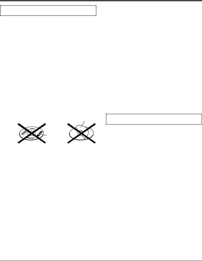
•Do not use any non-standard shape disc (like a heart, flower or credit card, etc.) available on the market, because it may damage the system.
•Do not use a disc with tape, stickers, or paste on it, because it may damage the system.
Label sticker
Sticker 
Paste
Note about copyright laws
Check the copyright laws in your country before recording from DVDs, Super Video CDs (SVCDs), Video CDs (VCDs) and Audio CDs. Recording of copyrighted material may infringe copyright laws.
Note about copyguard system
DVDs are protected by copyguard system. When you connect the system to your VCR directly, the copyguard system activates and the picture may not be played back correctly.
7 Safety precautions
Avoid moisture, water and dust
Do not place the system in moist or dusty places.
Avoid high temperatures
Do not expose the system to direct sunlight and do not place it near a heating device.
When you are away
When away on travel or for other reasons for an extended period of time, disconnect the power cord plug from the wall outlet.
Do not block the vents
Blocking the vents may damage the system.
Care of the cabinet
When cleaning the system, use a soft cloth and follow the relevant instructions on the use of chemically-coated cloths. Do not use benzene, thinner or other organic solvents including disinfectants. These may cause deformation or discoloring.
If water gets inside the system
Turn the system off and disconnect the power cord plug from the wall outlet, then call the store where you made your purchase. Using the system in this condition may cause fire or electrical shock.
Supplied accessories
Check to be sure you have all of the supplied accessories.
The number in parentheses is the quantity of the pieces supplied. If anything is missing, contact your dealer immediately.
•Remote control (1)
•Batteries (2)
•FM antenna (1)
•AM (MW) loop antenna (1)
•Power cord (1)
•System cord (1)
•Speaker cords
5 m: For satellite (front left/right) and center speakers (3) 10 m: For satellite speakers (surround left/right) (2) (Length of speaker cords is approximate.)
This product incorporates copyright protection technology that is protected by method claims of certain U.S. patents and other intellectual property rights owned by Macrovision Corporation and other rights owners. Use of this copyright protection technology must be authorized by Macrovision Corporation, and is intended for home and other limited viewing uses only unless otherwise authorized by Macrovision Corporation. Reverse engineering or disassembly is prohibited.
2
About discs
Playable disc types
This system has been designed to play back the following discs: DVD Video (DVD), Video CD (VCD), Super Video CD (SVCD), Audio CD, CD-R and CD-RW.
•This system can also play back MP3 and JPEG files recorded on CD-Rs and CD-RWs. (A pg. 21)
•This system can also play back finalized DVD-Rs recorded in DVD VIDEO format. However, some discs may not be played back because of their disc characteristics or recording conditions.
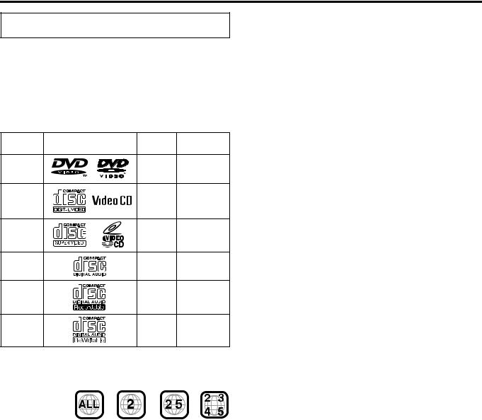
Discs you can play:
Disc Type |
Mark (Logo) |
Video |
Region Code |
|
Format |
Number* |
|||
|
|
|||
DVD |
|
PAL |
2/ALL |
|
VCD |
|
PAL |
— |
|
SVCD |
|
PAL |
— |
|
Audio CD |
|
— |
— |
|
CD-R |
|
— |
— |
|
CD-RW |
|
— |
— |
*Note on Region Code
DVD players and DVDs have their own Region Code numbers. This system can only play back DVDs recorded with the color system of PAL whose Region Code number includes “2”.
Examples:
If a DVD with an improper Region Code number is loaded, “REGION CODE ERROR!” appears on the TV screen and playback cannot start.
•The following discs cannot be played back:
DVD Audio, DVD-ROM, DVD-RAM, DVD-RW, CD-ROM, CD-I (CD-I Ready), Photo CD, etc.
Playing back these discs will generate noise and damage the speakers.
•On some DVDs, Video CDs or SVCDs, their actual operation may be different from what is explained in this manual. This is due to the disc programming and disc structure, not a malfunction of this system.
Notes on CD-R and CD-RW
•User-edited CD-Rs (Recordable) and CD-RWs (Rewritable) can be played back only if they are already “finalized”.
•This system can play back CD-Rs or CD-RWs recorded on a personal computer if they have been recorded in the audio CD format.
This system can also play back CD-Rs or CD-RWs if MP3 files or JPEG files are recorded on them.
However, some discs may not be played back because of their disc characteristics, recording conditions, or damage or stain on them.
Especially, the configuration and characteristics of an MP3 disc or a JPEG disc are determined by the writing (encoding) software and hardware used for recording. Therefore, due to the software and hardware used, the following symptoms may occur:
•Some discs may not be played back.
•Some tracks on an MP3 disc may be skipped or may not be played back normally.
•Some files on a JPEG disc may be played back distortedly.
•Before playing back CD-Rs or CD-RWs, read their instructions or cautions carefully.
•CD-RWs may require a longer readout time. This is caused by the fact that the reflectance of CD-RWs is lower than that of regular CDs.
About MP3 discs
MP3 is an abbreviation for Motion Picture Experts Group 1 (or MPEG-1) Audio Layer 3. MP3 is simply a compressed data file format. By using MP3 format, one CD-R or CD-RW can contain 10 times as much data as one regular CD.
About JPEG discs
A still-picture data compression system proposed by the Joint Photographic Expert Group, which features small decrease in image quality in spite of its high compression ratio.
Notes on MP3/JPEG discs
•MP3/JPEG discs (either CD-R or CD-RW) require a longer readout time. (It differs due to the complexity of the directory/file configuration.)
•When making an MP3/JPEG disc, select ISO 9660 Level 1 or Level 2 for the disc format.
•This system supports “multi-session” discs (up to 5 sessions).
•This system cannot play “packet write” discs.
•The system can only play MP3/JPEG files with the following file extensions;
MP3: “.MP3”, “.Mp3”, “.mP3” and “.mp3”
JPEG: “.jpg”, “.jpeg”, “.JPG”, “.JPEG” and any uppercase and lowercase combination (such as “.Jpg”)
•If both MP3 files and JPEG files are recorded on a disc, set the
MP3/JPEG setting in the PICTURE menu to the appropriate setting for the data to be read (“MP3” or “JPEG”). (A pg. 51)
•Some MP3/JPEG discs may not be played back because of their disc characteristics or recording conditions.
Notes on MP3 discs only
•ID3* tags cannot be shown on the display.
*An MP3 file can contain file information called an “ID3 Tag” where its album name, performer, track title, etc. are recorded. There are two versions, ID3v1 (ID3 Tag version 1) and ID3v2 (ID3 Tag version 2).
•We recommend to record each piece of material (song) at a sample rate of 44.1 kHz and at a data transfer rate of 128 kbps.
•Some tracks on an MP3 disc may be skipped or may not be played back normally.
Notes on JPEG discs only
•We recommend to record a file at 640 x 480 resolution. (If a file has been recorded at a resolution of more than 640 x 480, it will take a longer time to be displayed.)
•This system can only play baseline JPEG files*. Progressive JPEG files* or lossless JPEG files* cannot be played.
*Baseline JPEG format: Used for digital cameras, web, etc. Progressive JPEG format:Used for web.
Lossless JPEG format: An old type and rarely used now.
• Some files on a JPEG disc may be played back distortedly.
3
About discs
IMPORTANT
Before playing a disc, make sure of the following;
•Check the connection with the TV.
•Turn on your TV and select the correct input mode on the TV to view the pictures or on-screen information on the TV screen.
•For DVD playback, you can change the initial setting to your preference. (A pg. 48 – 55)
If Bappears on the TV screen when pressing a button;
The disc cannot accept the operation you have tried to do, or the information required for that operation is not recorded on the disc.
NOTICE: In some cases, without showing B, operations will not be accepted.
Disc structure
DVD
A DVD consists of “titles” and each title may be divided into “chapters”.
For example, if a DVD contains movies, each movie may have its own title number and may be further divided into chapters.
|
|
|
|
Title 1 |
|
|
|
|
|
|
Title 2 |
|||
|
|
|
|
|
|
|
|
|
|
|
|
|
|
|
|
Chapter 1 |
|
Chapter |
2 |
|
|
Chapter 3 |
|
Chapter 1 |
|
Chapter 2 |
|||
|
|
|
|
|
|
|||||||||
|
|
|
|
|
|
|||||||||
|
|
|
|
|
|
|
|
|
|
|
|
|
|
|
|
|
|
|
|
|
|
|
|
|
|
|
|
|
|
Video CD/SVCD/Audio CD
A Video CD, SVCD, Audio CD consists of “tracks”.
In general, each track has its own track number. (On some discs, each track may also be further divided by indexes.)
Track 1 |
|
Track 2 |
|
Track 3 |
|
Track 4 |
|
Track 5 |
||||
|
|
|
|
|
|
|
|
|
|
|
|
|
|
|
|
|
|
|
|
|
|
|
|
|
|
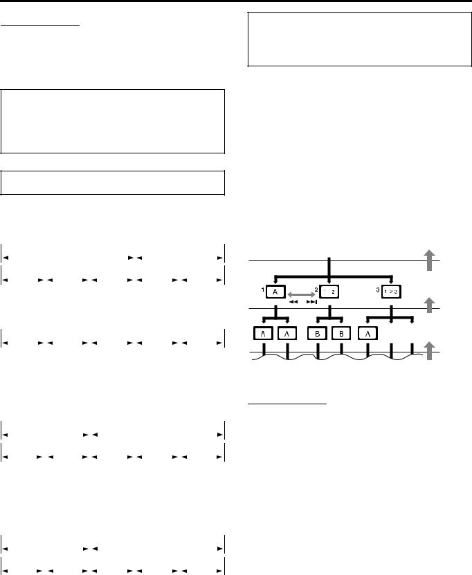
MP3 discs
On an MP3 disc, each song is recorded as a track (file). Tracks are usually grouped into a group (folder). Groups can also include other groups, creating hierarchical group layers. This system can recognize up to 150 tracks per group and up to 99 groups per disc.
•If there is any type of file other than MP3 files in a group (folder), those files are also counted in the total number of 150.
|
Group 1 |
|
|
|
|
|
Group 2 |
|
|
||||||
|
|
|
|
|
|
|
|
|
|
|
|
|
|
|
|
|
Track 1 |
|
|
Track 2 |
|
|
Group 3 |
|
Group 4 |
|
Group 5 |
||||
|
|
|
|
|
|
|
|||||||||
|
|
|
|
|
|
|
|||||||||
|
|
|
|
|
|
|
|
|
|
|
|
|
|
|
|
|
|
|
|
|
|
|
|
|
|
|
|
|
|
|
|
JPEG discs
On a JPEG disc, each still picture is recorded as a file. Files are usually grouped into a group (folder). Groups can also include other groups, creating hierarchical folder layers. This system can recognize up to 150 files per group and up to 99 groups per disc.
•If there is any type of file other than JPEG files in a group (folder), those files are also counted in the total number of 150.
|
Group 1 |
|
|
|
|
|
|
|
Group 2 |
|
|
|||||
|
|
|
|
|
|
|
|
|
|
|
|
|
|
|
|
|
|
File 1 |
|
|
|
File 2 |
|
|
Group 3 |
|
Group 4 |
|
Group 5 |
||||
|
|
|
|
|
|
|
|
|||||||||
|
|
|
|
|
|
|
|
|||||||||
|
|
|
|
|
|
|
|
|
|
|
|
|
|
|
|
|
|
|
|
|
|
|
|
|
|
|
|
|
|
|
|
|
|
Playback Control function (PBC) — VCD and SVCD only
The Playback Control function allows you to enjoy menu-driven operation and high-resolution still images which have a resolution four times greater than moving pictures.
High-resolution still image display
You can display high-quality images which are four times clearer than moving pictures.
Menu-driven playback
A selection menu is displayed when you start playing a Video CD or SVCD with the Playback Control feature. The selection menu shows a list of numbers for selection. Some discs may show moving pictures or a divided screen.
You can interact with the screen using a menu display to select and play an entry.
See example illustration below about basic features of menu-driven playback (for details about the operation through the menu, also see page 37).
 Menu screen
Submenu
Press RETURN.
Press

 RETURN.
Press RETURN.
A:Moving picture
B:Still picture
NOTE
•When operating a Video CD or SVCD using the menu, some functions such as Repeat Playback may not work.
4
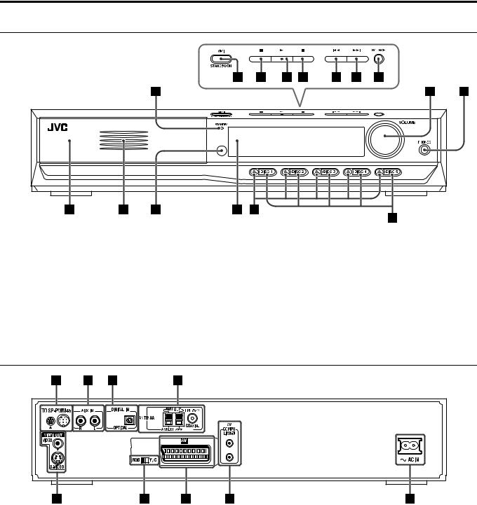
Names of parts and controls
Front panel (center unit)
A Standby lamp (STANDBY) A pg. 17 |
I Volume control (VOLUME) A pg. 18 |
B Standby-on button (FSTANDBY/ON) A pg. 17 |
J Headphones jack (PHONES) A pg. 18 |
C Stop button (7) A pg. 21 |
K Disc trays A pg. 21 |
D Play button (3) A pg. 21 |
L Illumination lamp A pg. 19 |
E Pause button (8) A pg. 21 |
M Remote sensor A pg. 14 |
F Reverse skip button (4) A pg. 24 |
N Display window A pg. 6, 22 |
G Forward skip button (¢) A pg. 24 |
O Open/close buttons (0) A pg. 21 |
H Source button (SOURCE) A pg. 18 |
P Disc buttons (DISC 1-5) A pg. 21 |
Rear panel (center unit)
A System cord connector A pg. 10
B Audio input jacks (AUX IN) A pg. 12
C Digital input jack (DIGITAL IN) A pg. 12
D Antenna terminals (ANTENNA) A pg. 9
E Video output jacks (VIDEO OUT) A pg. 8
VIDEO, S-VIDEO
F Video output signal selector (RGB-Y/C) A pg. 8
G AV (SCART) connector (AV) A pg. 8
HAV COMPU LINK-III jacks (for future use)
IÓAC IN socket A pg. 13
5
Names of parts and controls
Display window (center unit)
A Disc indicators A pg. 23 B MP3 indicator A pg. 22
C Channel indicator (CH) A pg. 26 D Main display A pg. 22
E Stereo indicator (ST) A pg. 25
F Tuning indicator (TUNED) A pg. 25
G Auto muting indicator (AUTO MUTING) A pg. 26
H• Source signal indicators (abcdghi) A pg. 32
• Subwoofer indicator (f) A pg. 32
• Sound reproducing speaker indicator ( ) A pg. 32
I• Dolby Pro Logic II indicator (GPLII) A pg. 31
•Linear PCM indicator (LPCM) A pg. 32
•Digital signal format indicators A pg. 32 Dolby Digital (GDIGITAL), DTS (C)
JSurround indicator (SURROUND) A pg. 33
KDSP indicator A pg. 31 – 33
LResume indicator (RESUME) A pg. 22
MRepeat mode indicators A pg. 46
NRDS reception mode indicators A pg. 27 – 30 RDS, TA, News, Info
Powered subwoofer
Rear |
A System cord connector A pg. 10
B Front speaker terminals (FRONT SPEAKERS) A pg. 11 C Center speaker terminals (CENTER SPEAKER) A pg. 11
D Surround speaker terminals (SURROUND SPEAKERS) A pg. 11 E Power cord A pg. 13
F Power lamp (POWER ON) A pg. 17
Front |
6

Names of parts and controls
Remote control
NOTE
• To use buttons I – W and g – p, slide down the remote control cover.
A Remote control mode selector A pg. 15 – 56
AUDIO, TV, VCR
B Muting button (MUTING) A pg. 18
CDisc buttons (DISC 1-5) A pg. 21
DTV volume buttons (TV VOL +/–) A pg. 15
EOperating buttons
•Play button (3) A pg. 22
•Forward/reverse skip buttons (¢/4) A pg. 24
•Fast-forward/reverse playback buttons (¡/1) A pg. 24
•Stop button (7) A pg. 21
•Pause button (8) A pg. 21
•Tuning buttons (TUNING ª, TUNING ·) A pg. 25
•Memory button (MEMORY) A pg. 26
•FM reception/Beat Cut mode button (FM MODE) A pg. 26
•Enhanced Other Network operating button (TA/NEWS/INFO) A pg. 29
•PTY selection buttons (PTY ª, PTY ·) A pg. 28
FTop menu button (TOP MENU) A pg. 36
G• Cursor buttons (3/2///5) A pg. 36
•Enter button (ENTER) A pg. 15
H• One Touch Replay button ( ) A pg. 23
•Record button (REC) A pg. 16
IAudio button (AUDIO) A pg. 41, 42
JSubtitle button (SUBTITLE) A pg. 41
KVFP setting button A pg. 44
LChoice menu button (CHOICE) A pg. 48
MSetting button (SETTING) A pg. 56
NTitle/group button (TITLE/GROUP) A pg. 37
ORepeat button (REPEAT) A pg. 46
PA-B repeat button (A-B REPEAT) A pg. 47
QSleep button (SLEEP) A pg. 19
RDimmer button (DIMMER) A pg. 19
SSurround buttons (SURROUND)
Mode (MODE), On/Off (ON/OFF) A pg. 33
TEffect button (EFFECT) A pg. 34
UTest tone button (TEST) A pg. 34
VSubwoofer adjustment buttons (S.WFR +/–) A pg. 20
WCenter speaker adjustment buttons (CENTER +/–) A pg. 34
XStandby-on button (FAUDIO) A pg. 17
YStandby-on button (FVCR) A pg. 16
ZStandby-on button (FTV) A pg. 15
a Source selecting buttons A pg. 18 DVD, FM/AM, AUX, TV SOUND
b TV/Video mode button (TV/VIDEO) A pg. 15 c Channel buttons (CHANNEL +/–) A pg. 15 d Volume buttons (AUDIO VOL +/–) A pg. 18 e • Menu button (MENU) A pg. 36
•PTY search button (PTY SEARCH) A pg. 28
f• On-screen button (ON SCREEN) A pg. 35
•RDS display button (RDS DISPLAY) A pg. 27
g• Number buttons A pg. 15, 24, 37
•TV returning button (TV RETURN) A pg. 15
hReturn button (RETURN) A pg. 4, 37
iAngle button (ANGLE) A pg. 40
jDecode mode button (DECODE) A pg. 20
kZoom button (ZOOM) A pg. 43
lCancel button (CANCEL) A pg. 45
mDisplay window button (FL DISPLAY) A pg. 22
nTreble adjustment buttons (TREBLE +/–) A pg. 20
oBass adjustment buttons (BASS +/–) A pg. 20
pSurround speaker adjustment buttons (SURR) A pg. 34 Left (L +/–), Right (R +/–)
7
Getting started
Connections
•Do not connect the AC power cord until all other connections have been made.
•Since different components often have different terminal names, carefully read the instructions supplied with the components you are going to connect.
Connecting a TV
To view pictures and on-screen displays, connect the TV to the center unit.
•Distortion of picture may occur when connecting to the TV via a VCR, or to a TV with a built-in VCR.
•You need to set “MONITOR TYPE” in the PICTURE menu correctly according to the aspect ratio of your TV. (A pg. 51)
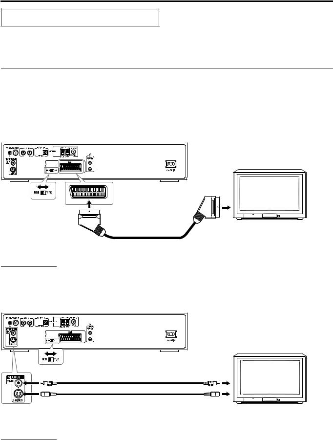
7 To connect a TV with the SCART connector
Connect the center unit’s AV (SCART) connector with your TV’s SCART connector using a SCART cable (not supplied).
•Set the RGB-Y/C selector correctly according to your TV.
•If the TV accomodates the RGB video signal, set the RGB-Y/C selector to “RGB” so that you can enjoy better-quality pictures.
•If the TV accomodates the S-video signal, set the RGB-Y/C selector to “Y/C”.
•If the TV accomodates the composite video signal only, set the RGB-Y/C selector to “RGB”.
Center unit
TV
RGB-Y/C selector
To AV (SCART) connector
To SCART connector*
SCART cable (not supplied)
* Some TV’s SCART connectors output audio signal. In such a case, you can enjoy the TV sound through this system.
NOTE
• No sound comes out from “AV” (SCART) connector.
7 To connect a TV through the composite or S-video jacks
Connect the TV using the composite video cord (not supplied) or an S-video cord (not supplied).
If your TV has an S-video (Y/C-separation) jack, you can get better picture quality than by using composite video connection.
• Connect the S-video cord by matching the /mark on the plug to the one on the rear of the center unit.
Center unit
RGB-Y/C selector* |
|
|
Composite video cord (not supplied) |
To composite video input |
TV |
|
|
|
or |
|
|
S-video cord (not supplied) |
To S-video input |
|
*When connecting an S-video cord, set the RGB-Y/C selector to “Y/C”.
When connecting a composite video cord, set the RGB-Y/C selector to “RGB”.
NOTE
•When the RGB-Y/C selector is set to “RGB”, correct video signal is not output from the S-VIDEO jack on the rear panel.
•Whether the RGB-Y/C selector is set to “RGB” or “Y/C”, the composite video signal is always output from the VIDEO jack of the VIDEO OUT.
8
Getting started
Connecting the FM and AM (MW) antennas
Make sure the antenna conductors do not touch any other terminals, connecting cords and power cords. This could cause poor reception.
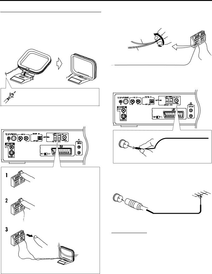
7 AM (MW) loop antenna
Setting up supplied AM (MW) loop antenna
Attach the AM (MW) loop to its base by snapping the tabs on the loop into the slot on the base.
If the antenna cord is covered with the insulation coat, twist and pull the insulation coat off and remove.
Connecting AM (MW) loop antenna
Center unit
Press and hold down the terminal clamp.
Insert the antenna cord.
Release finger from the clamp.
• Turn the loop antenna until you have the best reception.
If reception is poor
Connect an outdoor single vinyl-covered wire antenna (not supplied) to the AM EXT terminal. (Keep the AM (MW) loop antenna connected.)
• Twist together both wires.
AM (MW) loop antenna
Outdoor single vinyl-covered wire antenna (not supplied)
7 FM antenna
Connecting supplied FM antenna
Center unit
Extend the supplied FM antenna horizontally.
If reception is poor
Connect an outdoor FM antenna with standard type (75 C coaxial) connector.
Outdoor FM antenna (not supplied)
Outdoor FM antenna cord (not supplied)
NOTE
•Disconnect the supplied FM antenna before attaching a 75 C coaxial connector (the kind with a round wire going to an outdoor antenna).
•We recommend that you use coaxial cable for the FM antenna as it is well-shielded against interference.
9
Getting started
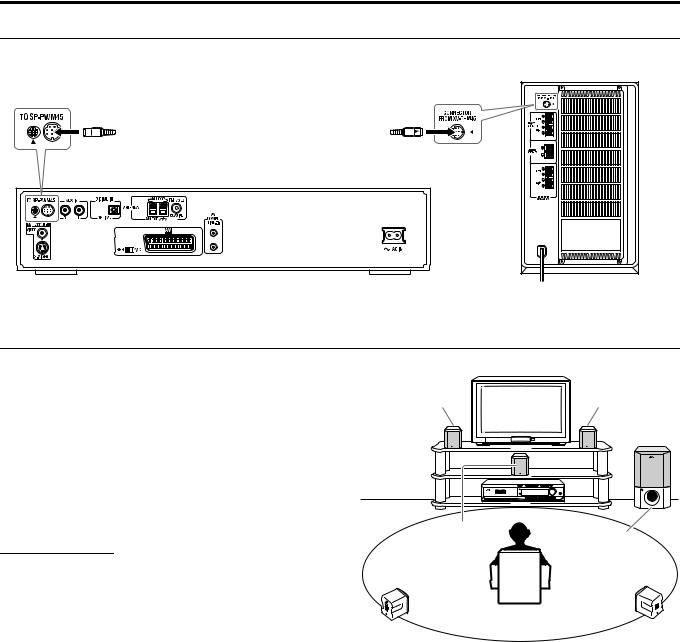
Connecting the powered subwoofer
Connect the supplied powered subwoofer (SP-PWM45) using the system cord (supplied).
• Connect the system cord by matching the 5marks on the plugs to the ones on the center unit and powered subwoofer.
System cord (supplied)
Ensure that the 5mark on the plug faces down.
Center unit
Powered subwoofer
Connecting the satellite speakers
7 Speaker layout
When positioning the speakers, to obtain the best possible sound from this system you need to place all satellite speakers at the same distance from the listening position with the front of each speaker facing toward the listener.
When you cannot place them at the same distance from the listening position, you can make adjustment so that speakers operate as if they are placed at the best position. (A pg. 52)
•Normally place the powered subwoofer in front of you. (Since bass sound is non-directional, you do not need to place it at the same distance as the other speakers.)
NOTE
•Although the satellite speakers and the powered subwoofer are magnetically shielded, the TV screen may appear mottled. In this case, keep the distance between them to the TV to over 10 cm.
•For safety reasons, always ensure that there is sufficient space behind the powered subwoofer.
•When you position the satellite speakers in a relatively high place, such as the top of your bookshelf, place them on a flat and level surface.
•Speaker grilles are not removable. Trying to remove them by force may damage them.
Front left |
Front right |
Center
speaker Powered subwoofer
Surround left |
Surround right |
10
Getting started
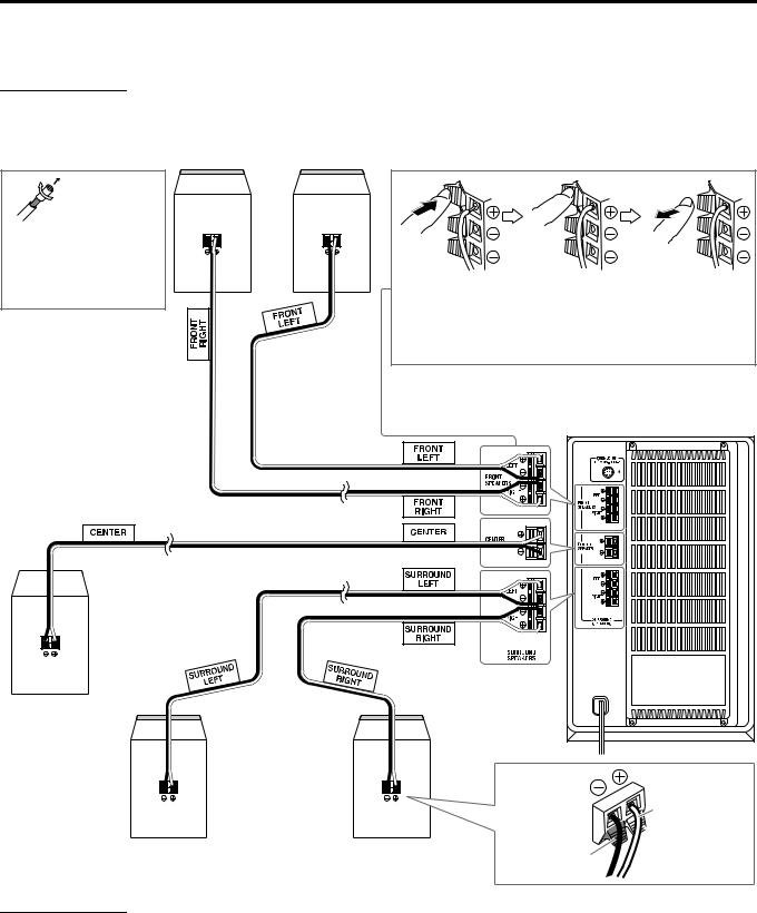
7 Connecting the satellite (front, center, surround) speakers
Be sure to identify each speaker (SP-THM45C/SP-THM45F/SP-THM45S) and connect them to the corresponding terminals of the powered subwoofer.
CAUTION
•When you connect (larger) speakers other than the supplied ones, only use speakers with the same speaker impedance (SPEAKER IMPEDANCE) as indicated by the speaker terminals on the rear of the powered subwoofer.
•DO NOT connect more than one speaker to one speaker terminal.
Front speakers (SP-THM45F)
Before connecting the speaker cords;
Twist and pull the insulation coat off and remove.
Press and hold |
Insert the bare end of the |
Release the |
the clamp. |
speaker cord into the |
clamp. |
|
terminal. |
|
•Connect the white cords to the red (ª) terminals and black cords to the black (·) terminals.
Center speaker |
Powered subwoofer |
(SP-THM45C) |
White
Black 
 Red
Red
Surround speakers |
Black |
|
(SP-THM45S) |
||
|
CAUTION
When installing the satellite speakers on the wall;
•Be sure to have them installed on the wall by a qualified personnel.
DO NOT install the satellite speakers on the wall by yourself to avoid unexpected damage from their falling off the wall due to incorrect installation or weakness in wall structure.
•Care must be taken in selecting a location for speaker installation on a wall. Injury to personnel or damage to equipment may result if the speakers installed interfere with daily activities.
11
Getting started
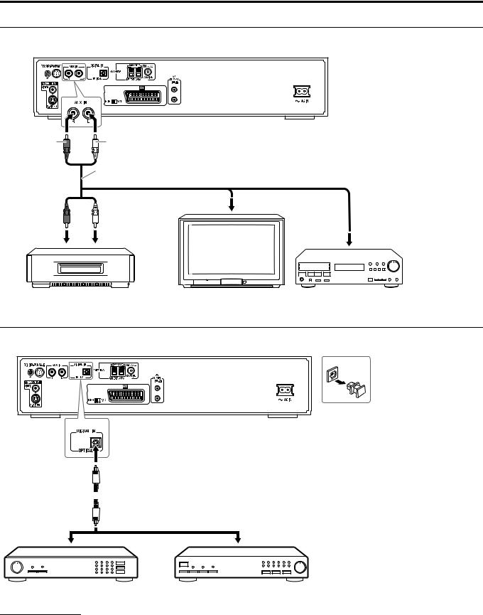
Connecting to an analog component
You can enjoy the sound of an analog component such as a VCR, TV, or Cassette recorder with this system. Use RCA pin plug cords (not supplied) for connection.
Center unit
Red |
White |
|
|
RCA pin plug cord (not supplied) |
|
|
|
To audio output |
|
To audio output |
To audio output |
|
|
|
|
|
|
|
|
|
|
|
|
|
|
|
|
|
|
|
|
|
|
|
|
|
|
|
|
|
|
|
|
|
|
|
|
|
|
|
|
|
|
|
|
|
|
|
|
|
|
|
|
|
|
|
|
|
|
|
|
|
|
|
|
|
|
|
|
|
|
|
|
|
|
|
|
|
|
|
|
|
|
|
|
|
|
|
|
|
|
|
|
|
|
|
|
|
|
|
|
|
|
|
|
|
|
|
|
VCR |
|
|
TV |
|
Cassette recorder |
|
||||||||||||||||||||
Connecting to a digital component
You can enjoy the sound of a digital component such as a DBS (Direct Broadcast Satellite) tuner or MD recorder with this system. Use digital optical cord (not supplied) for connection.
Before connecting a digital optical cord, unplug the protective plug.
Center unit
 Digital optical cord (not supplied)
To digital optical output
|
|
|
|
|
|
|
|
|
|
|
|
|
|
|
|
|
|
|
|
|
|
|
|
|
|
|
|
|
|
|
|
|
|
|
|
|
|
|
|
|
|
|
|
|
|
|
|
|
|
DBS tuner |
MD recorder |
||||||||
NOTE
•Only digital audio signals can be input when selecting “AUX DIGITAL” as the source to play. (A pg. 18) When connecting a video component such as a DBS tuner, operate this system to listen to the sound.
12
Getting started
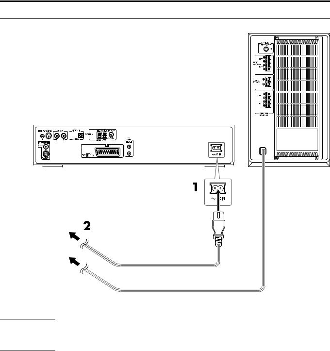
Connecting the power cord
Make sure that all connections have been completed, before plugging in the power cords of the center unit and powered subwoofer.
1 Firmly insert the supplied power cord into the ÓAC IN socket on the rear of the center unit.
2 Plug both power cords into AC outlets.
Center unit |
Powered subwoofer |
|
Plug into AC outlets.
Power cord (supplied)
Power cord
CAUTION
•Disconnect the power cord before cleaning or moving the system.
•Do not touch the power cord with wet hands.
•Do not pull on the power cord to unplug the cord. When unplugging the cord, always grasp and pull the plug so as not to damage the cord.
NOTE
•Keep power cords away from other connected cords. The power cords may cause noise or screen interference.
•Preset settings, such as preset stations and surround mode adjustment, may be erased in a few days in the following cases;
•If you unplug the power cord of the center unit.
•If a power failure occurs.
•The speakers will not produce any sound if the power cord of the powered subwoofer is removed from the AC outlet while the center unit is turned on. In this case, press FAUDIO on the remote control or FSTANDBY/ON on the center unit to turn the power off, plug in the powered subwoofer, then press FAUDIO or FSTANDBY/ON again.
13
Getting started
Using the remote control
The remote control makes it easy to use many of the system functions from a distance of up to 7 m away.
•You can also use the remote control supplied for this system to operate other manufacturers’ TVs (A pg. 15) and VCRs
(A pg. 16).
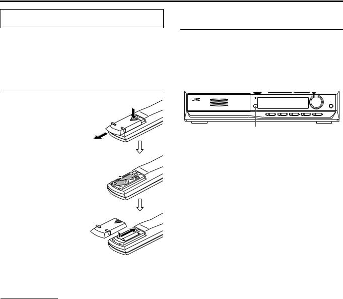
Putting batteries in the remote control
Before using the remote control, first put in the 2 supplied batteries.
1 Remove the battery cover on the back of the remote control.
2 Insert the batteries.
• Make sure to match polarity: (+) to
(+) and (–) to (–).
3 Replace the cover.
If the range or effectiveness of the remote control decreases, replace the batteries. Use two R6P (SUM-3)/AA (15F) type drycell batteries.
CAUTION
•Follow these precautions to avoid leaking or cracking batteries;
•Use the correct type of batteries. Batteries that look similar may differ in voltage.
•Always replace both batteries at the same time.
•Do not expose batteries to heat or flame.
Operating the system from the remote control
Aim the remote control directly at the remote sensor on the center unit.
•To control other components, aim the remote control directly at the remote sensor on each component. Refer also to their instruction manuals.
•To operate the remote control properly, do not hide the remote sensor by placing any obstructions in front of it.
Remote sensor
14

Getting started
|
4 Press number buttons (1-9, 0) to enter |
||||
|
the manufacturer’s code (2 digits). |
||||
|
Examples: |
|
|
|
|
Remote control |
For a Hitachi TV: Press 0, then 7. |
|
|||
For a Toshiba TV:Press 2, then 9. |
|
||||
mode selector |
|
|
|
|
|
|
Manufac- |
Code |
Manufactur- |
Code |
|
|
turer |
er |
|||
|
|
|
|||
|
JVC |
01 |
Nordmende |
13, 14, 18, 26 – 28 |
|
|
Akai |
02, 05 |
Okano |
09 |
|
|
Blaupunkt |
03 |
Orion |
15 |
|
(play button) |
Daewoo |
10, 31, 32 |
Panasonic |
16, 17 |
|
|
Fenner |
04, 31, 32 |
Philips |
10 |
|
|
Fisher |
05 |
Saba |
13, 14, 18, 26 – 28 |
|
|
Grundig |
06 |
Samsung |
10, 19, 32 |
|
|
Hitachi |
07, 08 |
Sanyo |
05 |
|
|
Inno-Hit |
09 |
Schneider |
02, 05 |
|
|
Irradio |
02, 05 |
Sharp |
20 |
|
|
Magnavox |
10 |
Sony |
21 – 25 |
|
|
Mitsubishi |
11, 33 |
Telefunken |
13, 14, 18, 26 – 28 |
|
Number |
Miver |
03 |
Thomson |
13, 14, 18, |
|
26 – 28, 30 |
|||||
buttons |
|
|
|
||
|
|
|
|
||
|
Nokia |
12, 34 |
Toshiba |
29 |
|
5
6
Release F TV.
Try operating your TV by pressing F TV.
When your TV turns on or off, you have entered the correct code.
If there is more than one code listed for corresponding brand, try each one until you enter the correct one.
NOTE
•Manufacturers’ codes are subject to change without notice. If they are changed, this remote control cannot operate the equipment.
•Set the codes again after replacing the batteries of the remote control.
For TV operations
You can operate your TV using the remote control supplied with this system.
• Refer also to the instruction manuals supplied with your TV.
7 To set the manufacturer’s code
You can operate a JVC TV without setting the remote control signal.
1 Slide the remote control mode selector to TV.
2 Press and hold F TV.
Keep the button pressed until step 4 is finished.
3 Press ENTER.
7 Operation
IMPORTANT
Before using the remote control to operate a TV;
• Set the remote control mode selector to TV.
The following buttons are available:
F TV: |
Turns TV on and off. |
TV VOL +/–: |
Adjusts the volume. |
TV/VIDEO: |
Selects the input mode (either TV or |
|
VIDEO). |
CHANNEL +/–: |
Changes the channels. |
1-10, 0, +10 (100+): Selects the channel. |
|
TV RETURN: |
Alternates between the previously selected |
|
channel and the current channel. |
15
Getting started
For VCR operations
You can operate your VCR using the remote control supplied with this system.
• Refer also to the instruction manuals supplied with your VCR.
7 To set the manufacturer’s code
1 Slide the remote control mode selector to VCR.
2 Press and hold FVCR.
Keep the button pressed until step 4 is finished.
3 Press ENTER.
4 Press number buttons (1-9, 0) to enter the manufacturer’s code (2 digits).
Examples:
For a Panasonic VCR: Press 2, then 1.
For a Philips VCR: Press 0, then 5.
Manufac- |
Code |
Manufac- |
Code |
||
turer |
turer |
||||
|
|
|
|||
|
|
|
|
|
|
JVC |
01 |
Nokia |
16 |
|
|
|
|
|
|
|
|
Aiwa |
02, 20 |
Nordmende |
17 |
– 19, 31 |
|
|
|
|
|
|
|
Bell+Howell |
03, 16 |
Orion |
20 |
|
|
|
|
|
|
|
|
Blaupunkt |
04 |
Panasonic |
21 |
|
|
|
|
|
|
||
CGM |
03, 05, 16 |
Philips |
05, 22 |
||
|
|
|
|
|
|
Daewoo |
34 |
Phonola |
05 |
|
|
|
|
|
|
||
Digtal |
05 |
Saba |
17 – 19, 23, 31 |
||
|
|
|
|
||
Fisher |
03, 16 |
Samsung |
24, 25 |
||
|
|
|
|
||
G.E. |
06 |
Sanyo |
03, 16 |
||
|
|
|
|
||
Grundig |
07 |
Sharp |
26, 27 |
||
|
|
|
|
|
|
Hitachi |
08, 09 |
Siemens |
07 |
|
|
|
|
|
|
|
|
Loewe |
05, 10, 11 |
Sony |
28 |
– 30, 35 |
|
|
|
|
|
|
|
Magnavox |
04, 05 |
Telefunken |
17 |
– 19, 31, 32 |
|
|
|
|
|
|
|
Mitsubishi |
12 – 15 |
Toshiba |
33 |
|
|
|
|
|
|
|
|
5 Release FVCR.
6 Try operating your VCR by pressing FVCR.
When your VCR turns on or off, you have entered the correct code.
If there is more than one cord listed for your brand, try each one until you enter the correct one.
NOTE
•Manufacturers’ codes are subject to change without notice. If they are changed, this remote control cannot operate the equipment.
•Set the codes again after replacing the batteries of the remote control.
7 Operation
IMPORTANT
Before using the remote control to operate a VCR;
• Set the remote control mode selector to VCR.
The following buttons are available:
FVCR: |
Turns VCR on and off. |
3(play button): Starts playback. |
|
7 : |
Stops operation. |
8 : |
Pauses playback. |
¢: |
Fast forwards video tape. |
4: |
Rewinds video tape. |
REC: |
Press this button together with 3(play button) to |
|
start recording or together with 8to pause |
|
recording. |
CHANNEL +/–: Changes the TV channels on the VCR.
16
 Loading...