


 Loading...
AUDIO/VIDEO CONTROL RECEIVER
RX-8010RBK / RX-8012RSL
CATV/DBS |
VCR 1 |
TV |
AUDIO |
|
|
|
|
|
|
|
|
|
|
|
|
|
DVD |
DVD MUILTI |
CD |
FM/AM |
|
|
|
|
|
|
|
|
|
|
|
|
|
TV/DBS |
VIDEO |
CDR |
PHONO |
|
|
|
|
|
|
|
|
|
|
|
|
|
VCR 1 |
VCR 2 |
TAPE/MD |
USB |
|
|
|
|
|
|
|
|
|
|
|
|
|
SURROUND |
DSP ANALOG/DIGITAL |
SLEEP |
|
|
|
|
|
|
|
|
|
|
|
|
|
|
ON/OFF |
MODE |
INPUT |
|
|
|
|
|
|
|
|
|
|
|
|
|
|
|
BASS |
|
ROOM |
|
|
|
|
|
|
AUDIO/VIDEO CONTROL RECEIVER |
|
|
|
|||
LINEDIF.ECT |
BOOST |
EFFECT |
SIZE |
|
|
|
|
|
|
|
|
|
|
|
|
|
|
1 |
2 |
3 |
|
|
|
|
|
|
|
|
|
|
|
|
|
MIDNIGHT |
TEST |
MENU |
FM/AM TUNING |
FM/AM PRESET |
|
FM MODE |
|
|
|
|
|
|
|
EON |
PTY SEARCH TA / NEWS / INFO DISPLAY MODE |
|
MODE |
CTRTONE |
LIVENESS |
|
|
|
|
|
|
|
|
|
|
|
|
|
|
|
4 |
5 |
6 |
STANDBY |
|
|
|
|
|
|
|
|
|
|
|
|
|
SUBWFR |
ENTER |
|
|
|
|
|
|
|
|
|
|
|
|
||
SOUND |
L/R BAL |
CENTER |
|
|
|
MEMORY |
|
|
|
|
|
|
|
|
|
|
|
7/P |
8 |
9 |
|
|
|
|
|
|
|
|
|
|
|
|
MASTER VOLUME |
MUTING DIGITALEQ REARL |
REARR |
STANDBY/ON |
|
|
|
|
|
|
|
|
|
|
|
|
||
|
|
|
|
|
|
|
|
|
|
|
|
|
||||
|
10 |
0 |
+10 |
D I G I T A L |
|
|
|
|
|
|
|
|
|
|
|
|
CATV/DBS |
RETURN |
FMMODE |
100+ |
SPEAKERS ON/OFF |
|
|
|
|
|
|
|
|
|
|
|
|
CONTROL |
+ BAL L + |
+ |
1 |
DSP MODE |
|
INPUT |
DVD MULTI |
DVD |
VCR 1 |
VCR 2 |
VIDEO |
TV SOUND/DBS |
DIGITAL |
LEVEL |
LINE DIRECT |
|
|
CH/ LEVEL TV VOL |
VOLUME |
SURROUND ON/OFF |
ANALOG/DIGITAL MIDNIGHT MODE |
|
|
|
|
|
|
EQ |
ADJUST |
||||
TV/VIDEO |
2 |
|
|
|
|
|
|
|
|
|
|
|
|
|||
|
− BAL R − |
− |
SUBWOOFER OUT ON/OFF |
|
|
INPUT ATT |
|
|
|
|
|
SOUCE NAME |
|
|
|
|
MENU |
|
PLAY |
EXIT |
|
|
|
|
|
|
|
|
|
|
|
||
|
USB AUDIO |
|
VIDEO |
|
|
|
|
|
|
EFFECT |
SETTING |
BASS BOOST |
||||
|
|
|
|
|
S-VIDEO |
VIDEO |
L—AUDIO—R |
PHONO |
CD |
CDR |
TAPE / MD |
USB AUDIO |
FM / AM |
|
|
|
TEXT |
/REW |
PAUSE |
FF/ |
|
|
|
|
|
|
|
|
|
|
|
|
|
DISPLAY |
|
|
|
|
|
|
|
|
|
|
|
|
|
CONTROL |
|
|
|
|
SET |
|
PUSH OPEN |
|
|
|
|
|
|
|
|
|
DOWN |
UP |
|
REC |
PTY–PTY SEARCH–PTY |
|
|
|
|
|
|
|
SOUCE NAME |
|
|
|
|
|
||
PAUSE |
DISPLAY |
|
|
|
|
|
|
|
|
|
|
|
|
|
|
|
|
MODE |
|
|
|
|
|
|
|
|
|
|
|
|
|
|
|
|
|
STOP |
CONTROL |
|
|
|
|
|
|
|
|
|
|
|
|
|
|
|
|
|
PHONES |
|
|
|
|
|
|
|
|
|
|
|
|
A/V CONTROL RECEIVER
D I G I T A L
INSTRUCTIONS
For Customer Use:
Enter below the Model No. and Serial No. which are located either on the rear, bottom or side of the cabinet. Retain this information for future reference.
Model No.
Serial No.
LVT0618-004A
[B]

Warnings, Cautions and Others
IMPORTANT for the U.K.
DO NOT cut off the mains plug from this equipment. If the plug fitted is not suitable for the power points in your home or the cable is too short to reach a power point, then obtain an appropriate safety approved extension lead or consult your dealer.
BE SURE to replace the fuse only with an identical approved type, as originally fitted.
If nonetheless the mains plug is cut off ensure to remove the fuse and dispose of the plug immediately, to avoid a possible shock hazard by inadvertent connection to the mains supply.
If this product is not supplied fitted with a mains plug then follow the instructions given below:
IMPORTANT.
DO NOT make any connection to the terminal which is marked with the letter E or by the safety earth symbol or coloured green or green-and-yellow.
The wires in the mains lead on this product are coloured in accordance with the following code:
Blue : Neutral
Brown : Live
As these colours may not correspond with the coloured markings identifying the terminals in your plug proceed as follows:
The wire which is coloured blue must be connected to the terminal which is marked with the letter N or coloured black.
The wire which is coloured brown must be connected to the terminal which is marked with the letter L or coloured red.
IF IN DOUBT - CONSULT A COMPETENT ELECTRICIAN.
CAUTION
To reduce the risk of electrical shocks, fire, etc.:
1.Do not remove screws, covers or cabinet.
2.Do not expose this appliance to rain or moisture.
Caution ––  switch!
Disconnect the mains plug to shut the power off completely. The  switch in any position does not disconnect the mains line. The power can be remote controlled.
CAUTION
•Do not block the ventilation openings or holes.
(If the ventilation openings or holes are blocked by a newspaper or cloth, etc., the heat may not be able to get out.)
•Do not place any naked flame sources, such as lighted candles, on the apparatus.
•When discarding batteries, environmental problems must be considered and local rules or laws governing the disposal of these batteries must be followed strictly.
•Do not use this apparatus in a bathroom or places with water. Also do not place any containers filled with water or liquids (such as cosmetics or medicines, flower vases, potted plants, cups, etc.) on top of this apparatus.
G-1

SAFETY INSTRUCTIONS
“SOME DOS AND DON’TS ON THE SAFE USE OF EQUIPMENT”
This equipment has been designed and manufactured to meet international safety standards but, like any electrical equipment, care must be taken if you are to obtain the best results and safety is to be assured.
Do read the operating instructions before you attempt to use the equipment.
Do ensure that all electrical connections (including the mains plug, extension leads and interconnections between pieces of equipment) are properly made and in accordance with the manufacturer’s instructions. Switch off and withdraw the mains plug when making or changing connections.
Do consult your dealer if you are ever in doubt about the installation, operation or safety of your equipment.
Do be careful with glass panels or doors on equipment.
DON’T continue to operate the equipment if you are in any doubt about it working normally, or if it is damaged in any way–switch off, withdraw the mains plug and consult your dealer.
DON’T remove any fixed cover as this may expose dangerous voltages.
DON’T leave equipment switched on when it is unattended unless it is specifically stated that it is designed for unattended operation or has a standby mode.
Switch off using the switch on the equipment and make sure that your family know how to do this.
Special arrangements may need to be made for infirm or handicapped people.
DON’T use equipment such as personal stereos or radios so that you are distracted from the requirements of traffic safety. It is illegal to watch television whilst driving.
DON’T listen to headphones at high volume as such use can permanently damage your hearing.
DON’T obstruct the ventilation of the equipment, for example with curtains or soft furnishings.
Overheating will cause damage and shorten the life of the equipment.
DON’T use makeshift stands and NEVER fix legs with wood screws — to ensure complete safety always fit the manufacturer’s approved stand or legs with the fixings provided according to the instructions.
DON’T allow electrical equipment to be exposed to rain or moisture.
ABOVE ALL
—NEVER let anyone, especially children, push anything into holes, slots or any other opening in the case -this could result in a fatal electrical shock.;
—NEVER guess or take chances with electrical equipment of any kind — it is better to be safe than sorry!
Caution: Proper Ventilation
To avoid risk of electric shock and fire and to protect from damage.
Locate the apparatus as follows:
Front: |
No obstructions open spacing. |
Sides: |
No obstructions in 10 cm from the sides. |
Top: |
No obstructions in 10 cm from the top. |
Back: |
No obstructions in 15 cm from the back |
Bottom: |
No obstructions, place on the level surface. |
In addition, maintain the best possible air circulation as illustrated.
Spacing 15 cm or more
RX-8010RBK/
RX-8012RSL
Front
Wall or obstructions
Stand height 15 cm or more
Floor
G-2

Table of Contents |
|
Parts Identification ...................................... |
2 |
Getting Started........................................... |
3 |
Before Installation ...................................................................... |
3 |
Checking the Supplied Accessories ........................................... |
3 |
Connecting the FM and AM (MW/LW) Antennas ..................... |
3 |
Connecting the Speakers ............................................................ |
4 |
Connecting Audio/Video Components ....................................... |
5 |
7Analog Connections ............................................................... |
5 |
7Digital Connections ................................................................ |
8 |
7USB Connection ..................................................................... |
9 |
Connecting the Power Cord ..................................................... |
10 |
Putting Batteries in the Remote Control .................................. |
10 |
Basic Operations ....................................... |
11 |
Turning the Power On and Off (Standby) ................................ |
11 |
Selecting the Source to Play ..................................................... |
11 |
Adjusting the Volume ............................................................... |
12 |
Selecting the Front Speakers .................................................... |
13 |
Muting the Sound ..................................................................... |
13 |
Listening at Night — Midnight Mode ..................................... |
13 |
Activating the Subwoofer Sound ............................................. |
14 |
Reinforcing the Bass ................................................................ |
14 |
Attenuating the Input Signal .................................................... |
14 |
Selecting the Line Direct Function .......................................... |
14 |
Adjusting the Equalization Patterns ......................................... |
15 |
Using the Sleep Timer .............................................................. |
15 |
Recording a Source .................................................................. |
15 |
Basic Settings........................................... |
16 |
Adjusting the Front Speaker Output Balance ........................... |
16 |
Changing the Source Name ...................................................... |
16 |
Setting the Subwoofer Information .......................................... |
17 |
Adjusting the Subwoofer Output Level .................................... |
17 |
Setting the Speakers for a Surround Field ................................ |
17 |
Digital Input (DIGITAL IN) Terminal Setting ......................... |
19 |
Selecting the Analog or Digital Input Mode ............................ |
20 |
Showing the Text Information on the Display ......................... |
22 |
Basic Setting and Adjustment — Auto Memory ...................... |
22 |
Receiving Radio Broadcasts ........................ |
23 |
Tuning in Stations Manually .................................................... |
23 |
Using Preset Tuning ................................................................. |
23 |
Selecting the FM Reception Mode ........................................... |
24 |
Using the RDS (Radio Data System) to |
|
Receive FM Stations .......................................................... |
25 |
Searching for a Program by PTY Codes .................................. |
25 |
Switching to a Broadcast Program of |
|
Your Choice Temporarily ................................................... |
27 |
Creating a Surround Field in Your Room ....... |
28 |
7Surround modes .................................................................... |
28 |
7DSP modes ........................................................................... |
28 |
Reproducing the Sound Field .................................................... |
29 |
Available DSP Modes According to the Speaker Arrangement |
.. 30 |
Adjusting the Surround Modes ................................................ |
31 |
Adjusting the DAP Modes ....................................................... |
32 |
Adjusting the Surround Modes with the DAP Modes .............. |
34 |
Adjusting the 5 CH/4 CH Stereo Mode ................................... |
36 |
Adjusting the 3D-PHONIC Modes .......................................... |
37 |
Using the DVD MULTI Playback Mode .......... |
39 |
Activating the DVD MULTI Playback Mode .......................... |
39 |
Using the On-Screen Menus ........................ |
40 |
7Showing the MENU on the TV Screen ................................ |
40 |
7Activating the Surround Modes ............................................ |
40 |
7Activating the DSP Modes ................................................... |
40 |
7Selecting the Analog or Digital Input Mode ........................... |
40 |
7Adjusting the Equalization Pattern ....................................... |
41 |
7Adjusting the Surround and DSP Modes .............................. |
41 |
7Adjusting the DVD MULTI Playback Mode ........................ |
42 |
7Listening at Night — Midnight Mode .................................. |
42 |
7Attenuating the Input Signal ................................................. |
42 |
7Selecting the Line Direct Function ....................................... |
43 |
7Selecting the Bass Boost Function ....................................... |
43 |
7Activating the Subwoofer Sound .......................................... |
43 |
7Operating the Tuner .............................................................. |
43 |
7Storing the Preset Stations .................................................... |
44 |
7Setting the Basic Setting Items ............................................. |
44 |
COMPU LINK Remote Control System ......... |
45 |
TEXT COMPU LINK Remote Control System .. |
46 |
7Showing the Disc Information on the TV Screen ................. |
47 |
7Searching for a Disc (Only for the CD player) .................... |
48 |
7Entering the Disc Information .............................................. |
49 |
Operating JVC’s Audio/Video Components ... |
51 |
Operating Audio Components .................................................. |
51 |
Operating Video Components .................................................. |
53 |
Operating Other Manufacturers’ Video |
|
Equipment ............................................ |
54 |
Troubleshooting ......................................... |
57 |
Specifications............................................ |
59 |
1
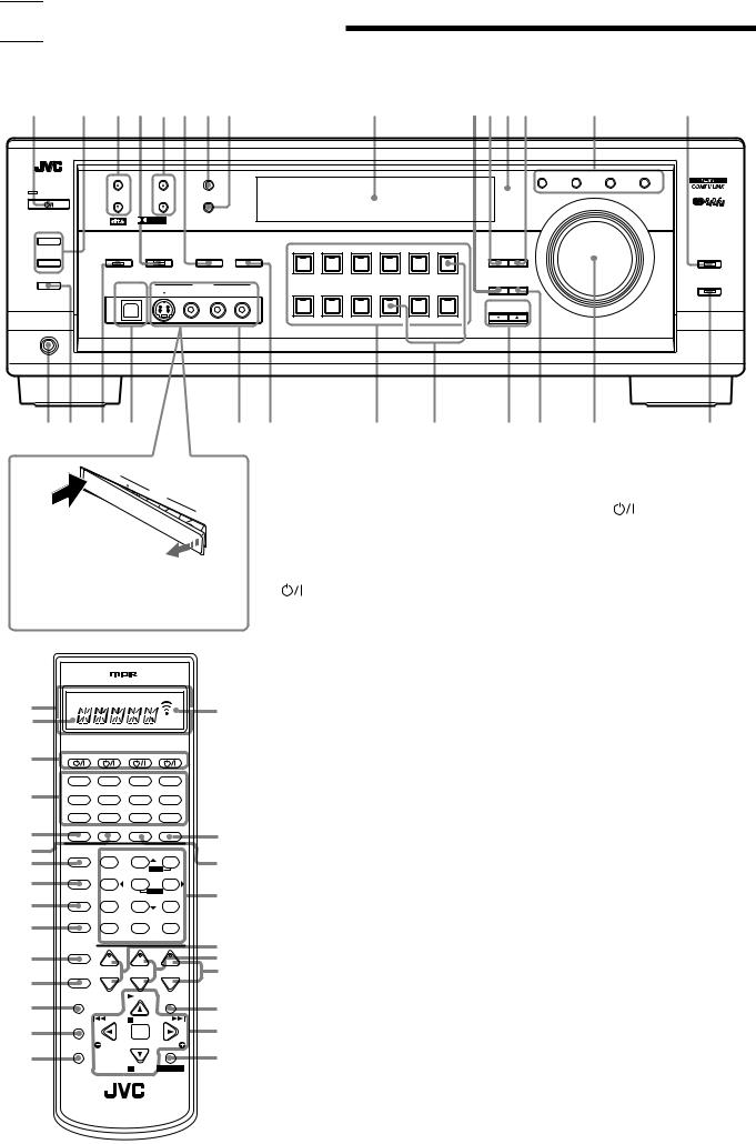

 Parts Identification
Become familiar with the buttons and controls on the receiver before use.
Refer to the pages in parentheses for details.
1 |
2 |
3 4 5 6 7 8 |
9 |
pqwe |
r |
t |
||
|
|
|
|
|
AUDIO/VIDEO CONTROL RECEIVER |
|
|
|
|
|
FM/AM TUNING |
FM/AM PRESET |
FM MODE |
|
EON |
PTY SEARCH TA / NEWS / INFO |
DISPLAY MODE |
|
|
|
|
|
|
|||
STANDBY |
|
|
|
|
|
|
|
|
|
|
|
|
MEMORY |
|
|
|
MASTER VOLUME |
|
|
|
|
|
|
|
|
|
STANDBY/ON |
|
D I G I T A L |
|
|
|
|
|
|
|
|
|
|
|
|
|
|
|
|
|
S U R R O U N D |
D I G I T A L |
|
|
|
|
|
SPEAKERS ON/OFF
|
1 |
|
|
|
|
|
|
|
|
|
|
|
|
|
|
|
|
|
|
|
|
|
|
|
|
|
|
|
|
|
|
|
INPUT |
|
|
DVD MULTI |
DVD |
VCR 1 |
VCR 2 |
VIDEO |
TV SOUND/DBS |
|
|
|
|
|
|
|
|
|
|
|
|
|
|
|
|
|
|
|
|
|
DIGITAL LEVEL |
|
|
|||
|
|
|
SURROUND ON/OFF DSP MODE |
ANALOG/DIGITAL |
MIDNIGHT MODE |
|
|
|
|
|
|
EQ |
ADJUST |
|
LINE DIRECT |
|||||||
|
2 |
|
|
|
|
|
|
|
|
|
|
|
|
|
|
|
|
|
|
|
|
|
|
|
|
|
|
|
|
|
|
|
INPUT ATT |
|
|
|
|
|
|
|
|
|
|
|
|
SUBWOOFER OUT ON/OFF |
|
|
|
|
|
|
|
|
|
|
|
|
|
|
|
|
SOURCE NAME |
|
|
|
|
|
|
|
|
|
USB AUDIO |
|
VIDEO |
|
|
|
|
|
|
|
EFFECT SETTING |
|
BASS BOOST |
||||||
|
|
|
|
|
|
|
|
|
|
|
|
|
|
|
|
|
||||||
|
|
|
|
|
|
|
S-VIDEO |
VIDEO |
L—AUDIO—R |
|
PHONO |
CD |
CDR |
TAPE / MD |
USB AUDIO |
FM / AM |
|
|
|
|
||
|
|
|
|
|
|
|
|
|
|
|
|
|
|
|
|
|
||||||
|
|
|
|
|
|
|
|
|
|
|
|
|
|
|
|
|
|
|
CONTROL |
|
|
|
|
|
|
|
|
|
|
|
|
|
|
|
|
|
|
|
|
|
DOWN |
UP |
|
|
|
|
|
|
|
|
|
|
|
|
|
|
|
|
|
|
SOURCE NAME |
|
|
|
|
|
|
|
PHONES |
|
|
|
|
|
|
|
|
|
|
|
|
|
|
|
|
|
|
|
|
|
|
|
y u i o |
|
|
|
; a |
|
|
s d |
f g h |
j |
||||||||||||
|
USB |
AUDIO |
|
|
|
|
|
|
|
|
|
|
|
|
|
|
|
|
|
|
|
|
|
|
|
|
|
|
|
|
|
|
|
|
|
|
|
|
|
|
|
|
|
|
|
|
PUSH |
|
|
S- |
VIDEO |
|
|
|
|
Remote Control |
|
|
|
|
Front Panel |
|
||||||
|
OPEN |
|
|
|
|
|
|
|
|
|
|
|
||||||||||
|
|
|
|
VIDEOVIDEO |
|
|
|
|
|
|
|
|
||||||||||
|
|
|
|
|
|
|
|
|
|
|
|
|
|
|||||||||
|
|
|
|
|
|
|
|
L— |
|
|
|
1 |
Display window (11) |
|
|
|
|
1 |
STANDBY/ON |
button and STANDBY |
||
|
|
|
|
|
|
|
|
AUDIO— |
|
|
|
|
|
|
||||||||
|
|
|
|
|
|
|
|
|
R |
|
|
|
|
|
|
|||||||
|
|
|
|
|
|
|
|
|
|
|
|
|
a. Remote control operation mode indicator |
|
|
lamp (11) |
|
|||||
|
|
|
|
|
|
|
|
|
|
|
|
|
b. Signal transmission indicator |
|
|
2 |
• SPEAKERS ON/OFF 1 button (13) |
|||||
|
|
|
|
|
|
|
|
|
|
|
|
|
Lights up when transmitting the remote |
|
|
• SPEAKERS ON/OFF 2 button (13) |
||||||
When using the VIDEO input terminals |
|
|
control signal. |
|
|
|
|
3 |
FM/AM TUNING 5/ buttons (23) |
|||||||||||||
and/or USB AUDIO terminal on the front |
2 |
buttons (11, 53 – 56) |
|
|
4 |
DSP MODE button and lamp (30, 32 – 37 ) |
||||||||||||||||
panel, detach the terminal cover. |
|
|
|
CATV/DBS, VCR 1, TV, AUDIO |
|
|
5 |
FM/AM PRESET 5/ buttons (23, 24) |
||||||||||||||
|
|
|
|
|
|
|
|
|
|
|
|
3 |
Source selecting buttons (11) |
|
|
6 |
• INPUT ANALOG/DIGITAL button (20) |
|||||
|
|
|
|
|
|
|
|
|
|
|
|
|
DVD,DVDMULTI,CD,FM/AM,TV/DBS,VIDEO, |
|
|
• INPUT ATT button (14) |
||||||
|
|
|
|
|
|
|
|
|
|
|
|
|
CDR, PHONO, VCR 1,VCR 2, TAPE/MD, USB |
|
7 |
FM MODE button (24) |
|
|||||
|
|
|
|
|
|
|
|
|
|
|
|
4 |
SURROUND ON/OFF button (30, 31, 34) |
|
8 |
MEMORY button (23) |
|
|||||
|
|
|
|
|
|
|
|
|
|
|
|
5 |
DSP MODE button (30, 33 – 38) |
|
|
9 |
Display (11) |
|
||||
1 |
|
|
|
|
|
|
|
|
|
b |
|
6 |
LINE DIRECT button (14) |
|
|
|
p EFFECT button (32 – 38) |
|||||
|
|
|
|
|
|
|
|
|
|
|
MIDNIGHT MODE button (13) |
|
|
q DIGITAL EQ button (15) |
||||||||
a |
|
|
|
|
|
|
|
|
|
|
|
7 |
|
|
||||||||
|
|
|
|
|
|
|
|
|
|
|
|
8 |
SOUND button (14 – 17, 31 – 39, 51) |
|
w Remote sensor (10) |
|
||||||
2 |
CATV/DBS |
|
VCR 1 |
|
|
TV |
AUDIO |
|
|
|
9 |
MUTING button (13) |
|
|
|
|
e LEVEL ADJUST button (16, 17, 32 – 39) |
|||||
|
|
|
|
|
|
|
|
|
|
|
0 |
CATV/DBS CONTROL button (55) |
|
r RDS operation buttons (25 – 27) |
||||||||
|
DVD |
DVD MUILTI |
|
CD |
FM/AM |
|
|
|
|
|||||||||||||
3 |
TV/DBS |
|
VIDEO |
|
|
CDR |
PHONO |
|
|
|
- TV/VIDEO button (53, 54) |
|
|
|
|
EON, PTY SEARCH, TA/NEWS/INFO, |
||||||
|
|
|
|
|
|
= MENU button (40 – 44) |
|
|
|
|
DISPLAY MODE |
|
||||||||||
|
|
|
|
|
|
|
|
|
|
|
|
|
|
|
|
|||||||
|
VCR 1 |
|
VCR 2 |
|
TAPE/MD |
USB |
|
|
|
|
|
|
|
|
||||||||
|
|
|
|
|
|
~ TEXT DISPLAY button (47 – 50) |
|
t LINE DIRECT button and lamp (14) |
||||||||||||||
|
SURROUND |
|
DSP |
ANALOG/DIGITAL |
SLEEP |
|
|
|
|
|||||||||||||
4 |
|
|
@ |
|
! REC PAUSE button (52, 53, 55) |
|
|
y PHONES jack (13) |
|
|||||||||||||
ON/OFF |
|
MODE |
|
|
INPUT |
|
|
|
|
|
|
|||||||||||
|
|
|
|
|
|
|
|
|
|
|
|
|
||||||||||
5 |
|
|
BASS |
|
|
|
ROOM |
|
|
|
@ SLEEP button (15) |
|
|
|
|
u SUBWOOFER OUT ON/OFF button (14) |
||||||
LINEDIF.ECT |
|
BOOST |
|
EFFECT |
SIZE |
|
# |
|
|
|
|
|
||||||||||
6 |
|
|
1 |
|
|
|
2 |
3 |
|
|
# ANALOG/DIGITAL INPUT button (21) |
|
i SURROUND ON/OFF button and lamp (30, 32, |
|||||||||
|
MIDNIGHT |
|
|
|
|
|
MENU |
|
|
|
|
|||||||||||
7 |
MODE |
|
TEST |
|
CTRTONE |
LIVENESS |
|
|
|
$ • 10 keys for selecting preset channels (24) |
|
|
35) |
|
||||||||
|
|
4 |
|
|
|
5 |
6 |
|
|
|
|
|
|
|||||||||
|
|
SUBWFR |
|
ENTER |
|
|
|
|
• 10 keys for adjusting sound (14 – 17, 31 – 39, |
o USB AUDIO terminal (9) |
||||||||||||
8 |
SOUND |
L/R BAL |
CENTER |
|
$ |
|
|
|||||||||||||||
|
|
7/P |
|
|
8 |
9 |
|
|
|
|
|
|
|
|
|
|
|
|
|
|
||
9 |
MUTING DIGITALEQ REARL |
REARR |
|
|
|
|
51) |
|
|
|
|
|
|
; VIDEO input terminals (7) |
||||||||
|
|
10 |
|
|
|
0 |
+10 |
|
|
|
|
• 10 keys for operating audio/video components |
|
a MIDNIGHT MODE button (13) |
||||||||
|
|
|
RETURN |
|
FMMODE |
100+ |
|
% |
|
|
|
|||||||||||
|
CATV/DBS |
|
+ |
BAL L |
+ |
+ |
|
|
|
(51 – 56) |
|
|
|
|
|
s Source selecting buttons and lamps (11) |
||||||
0 |
CONTROL |
|
|
^ |
|
|
|
|
|
|
|
|||||||||||
|
|
|
|
|
|
|
|
|
|
|||||||||||||
|
|
|
|
|
|
|
% • LEVEL +/– buttons* (15, 17, 31 – 39) |
|
|
|
|
|||||||||||
- |
TV/VIDEO |
CH/ LEVEL TV VOL |
VOLUME |
|
& |
|
|
|
DVD MULTI, DVD, VCR 1, VCR 2, VIDEO, TV |
|||||||||||||
|
|
− |
|
|
|
− |
− |
|
|
|
|
• BAL L and BAL R buttons* (16) |
|
|
SOUND/DBS, PHONO, CD, CDR, TAPE/MD, |
|||||||
|
MENU |
|
|
BAL R PLAY |
EXIT |
|
|
|
|
• CH +/– buttons (53 – 55) |
|
|
|
USB AUDIO, FM/AM |
|
|||||||
= |
|
|
|
|
|
|
|
* |
|
|
|
|
|
|
||||||||
|
|
|
|
|
|
|
|
|
|
^ TV VOL +/– buttons (53, 54) |
|
|
d SOURCE NAME buttons (16) |
|||||||||
|
TEXT |
|
/REW |
|
PAUSE |
FF/ |
|
|
|
|
|
|||||||||||
~ |
DISPLAY |
|
|
|
|
|
|
|
|
( |
|
& VOLUME +/– buttons (12) |
|
|
f CONTROL UP 5/DOWN buttons |
|||||||
|
|
|
|
|
|
SET |
|
|
|
|
|
|||||||||||
|
|
|
|
|
|
|
|
|
|
|
|
|||||||||||
|
REC |
|
PTY–PTY SEARCH–PTY |
|
|
|
* EXIT button (40 – 44, 47 – 49) |
|
|
g SETTING button (17 – 19, 22) |
||||||||||||
! |
PAUSE |
|
DISPLAY |
|
|
|
) |
|
|
|
||||||||||||
|
|
MODE |
|
|
|
|
( • RDS operation buttons (25 – 27, 51) |
|
h MASTER VOLUME control (12) |
|||||||||||||
|
|
|
|
|
|
STOP CONTROL |
|
|
|
|
||||||||||||
|
|
|
|
|
|
|
|
|
|
|
PTY SEARCH, PTY +/–, DISPLAY MODE |
|
j BASS BOOST button and lamp (14) |
|||||||||
|
|
|
|
|
|
|
|
|
|
|
|
|
|
|||||||||
|
|
|
|
|
|
|
|
|
|
|
|
|
• On screen operation buttons (40 – 44, 47– 50) |
|
|
|
||||||
|
A/V CONTROL RECEIVER |
|
|
|
|
|
• Operating buttons for audio/video components |
|
* These buttons function only after pressing |
|||||||||||||
|
|
|
|
|
|
|
|
|
|
|
|
|
(51 – 56) |
|
|
|
|
|
10 keys on the remote control which are |
|||
|
|
|
|
|
|
|
|
|
|
|
|
) CONTROL button (51 – 53) |
|
|
marked with an asterisk (*). |
|||||||
|
|
|
|
|
|
|
|
|
|
|
|
|
|
|
|
|
|
|
|
|
|
2 |

 Getting Started
This section explains how to connect audio/video components and speakers to the receiver, and how to connect the power supply.
Before Installation
General
•Be sure your hands are dry.
•Turn the power off to all components.
•Read the manuals supplied with the components you are going to connect.
Locations
•Install the receiver in a location that is level and protected from moisture.
•The temperature around the receiver must be between –5˚ C and 35˚ C (23˚ F and 95˚ F).
•Make sure there is good ventilation around the receiver. Poor ventilation could cause overheating and damage the receiver.
Handling the receiver
•Do not insert any metal object into the receiver.
•Do not disassemble the receiver or remove screws, covers, or cabinet.
•Do not expose the receiver to rain or moisture.
Checking the Supplied Accessories
Check to be sure you have all of the following items, which are supplied with the receiver.
The number in the parentheses indicates quantity of the pieces supplied.
•Remote Control (1)
•Batteries (2)
•AM (MW/LW) Loop Antenna (1)
•FM Antenna (1)
If anything is missing, contact your dealer immediately.
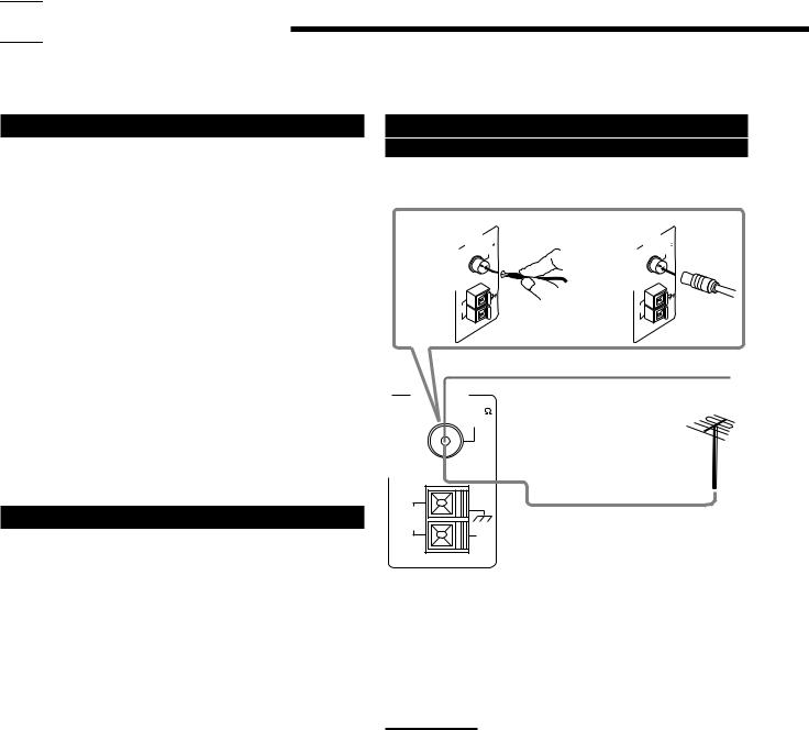
Connecting the FM and AM (MW/LW)
Antennas
FM Antenna Connections
A |
ANTENNA |
75 |
B |
ANTENNA |
75 |
FM |
FM |
||||
|
COAXIAL |
|
COAXIAL |
||
|
AM |
AM |
|
AM |
AM |
|
EXT |
|
EXT |
||
|
LOOP |
|
LOOP |
||
|
|
|
|
||
FM Antenna
ANTENNA |
Extend the supplied FM antenna horizontally. |
|
|
FM 75 |
|
COAXIAL |
|
AM |
Outdoor FM Antenna Cable |
LOOP |
AM
EXT
A.Using the Supplied FM Antenna
The FM antenna provided can be connected to the FM 75 Ω COAXIAL terminal as temporary measure.
B.Using the Standard Type Connector (Not Supplied)
A standard type connector (IEC or DIN45325) should be connected to the FM 75 Ω COAXIAL terminal.
Note:
If reception is poor, connect the outdoor antenna.
Before attaching a 75 Ω coaxial cable (the kind with a round wire going to an outdoor antenna), disconnect the supplied FM antenna.
3
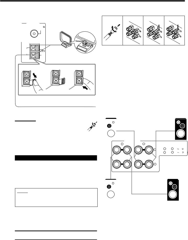
AM (MW/LW) Antenna Connections
Snap the tabs on the loop into the
ANTENNA |
slots of the base to assemble the |
|
FM 75 |
||
AM (MW/LW) loop. |
||
COAXIAL |
||
|
AM |
AM (MW/LW) |
|
LOOP |
|
|
AM |
Loop Antenna |
|
EXT |
|
|
1 |
2 |
3 |
Outdoor single vinyl-covered wire (not supplied)
Turn the loop until you have the best reception.
Notes:
• If the AM (MW/LW) loop antenna wire is covered with vinyl, remove the vinyl by twisting it as shown in the diagram.
•Make sure the antenna conductors do not touch any other terminals, connecting cords and power cord. This could cause poor reception.
•If reception is poor, connect an outdoor single vinyl-covered wire to the AM EXT terminal. (Keep the AM (MW/LW) loop antenna connected.)
Connecting the Speakers
You can connect the following speakers:
•Two pairs of front speakers to produce normal stereo sound.
•One pair of rear speakers to enjoy the surround effect.
•One center speaker to produce more effective surround effect (to emphasize human voices).
•One subwoofer to enhance the bass.
IMPORTANT:
After connecting the speakers listed above, set the speaker setting information properly to obtain the best possible Surround and DSP effect. For details, see page 17.
For each speaker (except for a subwoofer), connect the (+) and (–) terminals on the rear panel to the (+) and (–) terminals marked on the speakers. For connecting a subwoofer, see page 5.
CAUTION:
Use speakers with the SPEAKER IMPEDANCE indicated by the speaker terminals.
Basic connecting procedure
1 |
2 |
3 |
4 |
1Cut, twist and remove the insulation at the end of each speaker signal cable (not supplied).
2Turn the knob counterclockwise.
3Insert the speaker signal cable.
4Turn the knob clockwise.
Connecting the front speakers
You can connect two pairs of front speakers (one pair to the FRONT SPEAKERS 1 terminals, and another pair to the FRONT SPEAKERS 2 terminals).
Right speaker |
|
FRONT SPEAKERS 1 |
|
Left speaker |
||
|
|
|||||
|
|
|
|
|
|
|
|
|
|
|
|
|
|
FRONT SPEAKERS |
|
|
|
|
|
RIGHT 2 LEFT |
RIGHT 1 LEFT |
CAUTION : SPEAKER IMPEDANCE |
|||
|
+ |
1 |
OR |
2 : 8 |
16 |
|
|
1 |
AND |
2 : 16 |
32 |
–
|
|
|
|
|
|
|
Right speaker |
|
FRONT SPEAKERS 2 |
|
Left speaker |
||
|
|
|||||
4
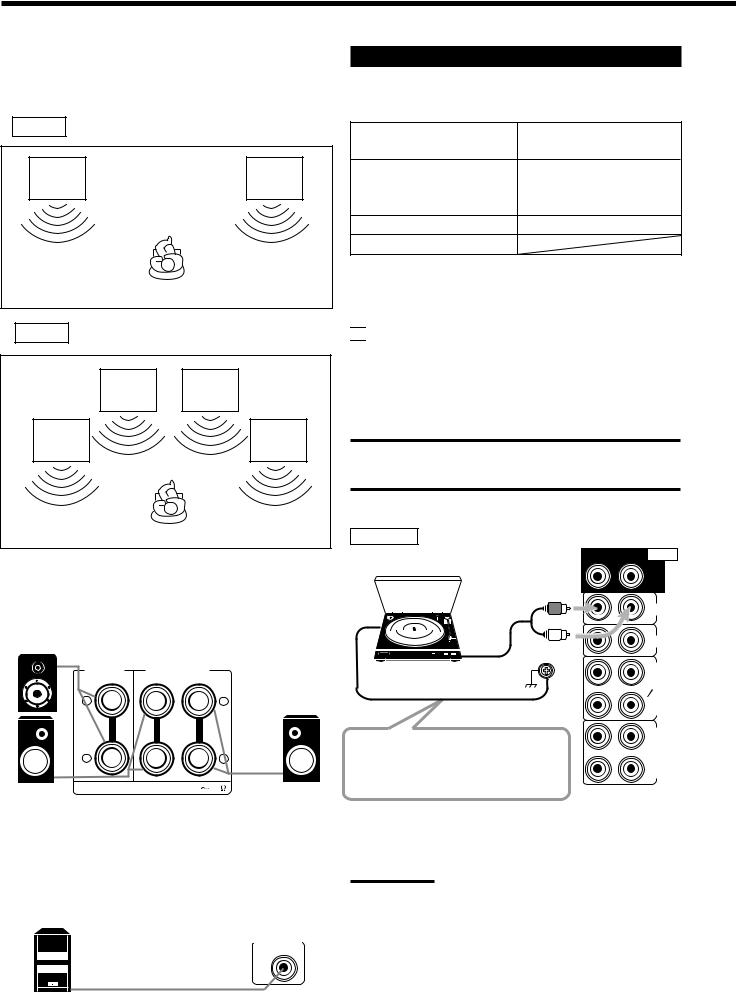
About the speaker impedance
The required speaker impedance of the front speakers does differ depending on whether both the FRONT SPEAKERS 1 and FRONT SPEAKERS 2 terminals are used or only one of them is used.
CASE 1 When you connect only one pair of front speakers
Front |
Front |
speaker |
speaker |
1 |
1 |
Use front speakers with 8 Ω – 16Ω impedance.
CASE 2 When you connect two pairs of front speakers
Front |
Front |
speaker |
speaker |
2 |
2 |
Front |
Front |
speaker |
speaker |
1 |
1 |
Use front speakers with 16 Ω – 32Ω impedance.
Connecting the rear and center speakers
Connect rear speakers to the REAR SPEAKERS terminals and a center speaker to the CENTER SPEAKER terminals.
Center speaker
|
CENTER |
REAR SPEAKERS |
|
|
|
SPEAKER |
|
||
|
|
RIGHT |
LEFT |
|
|
+ |
|
|
+ |
|
– |
|
|
– |
Right rear |
CAUTION : SPEAKER IMPEDANCE |
8 16 |
Left rear |
|
|
|
|
||
speaker |
|
|
|
speaker |
Connecting the subwoofer speaker
You can enhance the bass by connecting a subwoofer. Connect the input jack of a powered subwoofer to the
SUBWOOFER OUT jack on the rear panel, using a cable with RCA pin plugs (not supplied).
SUBWOOFER
OUT
Powered subwoofer
Connecting Audio/Video Components
You can connect the following audio/video components to this receiver. Refer also to the manuals supplied with your components.
Audio Components |
Video Components |
• Turntable |
• DVD player* |
• CD player* |
• TV* |
|
|
• Cassette deck or |
• DBS tuner* |
MD recorder* |
• VCR(s) |
• CD recorder* |
• Video camera |
•Personal computer (PC)
*You can connect these components using the methods described in
“Analog connections” (below), or in “Digital connections” (see page 8).

 Analog Connections
Audio component connections
Use the cables with RCA pin plugs (not supplied).
Connect the white plug to the audio left jack, and the red plug to the audio right jack.
CAUTION:
If you connect a sound-enhancing device such as a graphic equalizer between the source components and this receiver, the sound output through this receiver may be distorted.
Turntable
Turntable
To audio output
If an earth cable is provided for your turntable, connect the cable to the screw marked (H) on the rear panel.
Ex.: This connection is for the turntable with an MM (movingmagnet) type cartridge.
Note:
RIGHT LEFT AUDIO
REAR
PHONO
CD
OUT (REC)
TAPE MD
IN (PLAY)
OUT (REC)
CDR
IN (PLAY)
Any turntables incorporating a small-output cartridge such as an MC
(moving-coil) type must be connected to this receiver through a commercial head amplifier or step-up transformer. Direct connection may result in insufficient volume.
5

CD player |
RIGHT |
LEFT |
AUDIO |
|
|
||
|
|
|
REAR |
PHONO
CD player
|
CD |
|
|
OUT |
|
|
(REC) |
|
To audio output |
TAPE |
|
MD |
||
|
IN |
|
|
(PLAY) |
|
|
OUT |
|
|
(REC) |
|
Cassette deck or MD recorder |
CDR |
|
IN |
||
|
||
|
(PLAY) |
Cassette deck
To audio input 


 To audio output
RIGHT LEFT AUDIO
REAR
PHONO
CD
OUT (REC)
TAPE MD
IN (PLAY)
To audio input  To audio output MD recorder
Note:
You can connect either a cassette deck or an MD recorder to the
TAPE/MD jacks. When connecting an MD recorder to the TAPE/MD jacks, change the source name, which will be shown on the display when selected as the source, to “MD.” See page 16 for details.
CD recorder
CD recorder
To audio input  To audio output
RIGHT LEFT AUDIO
REAR
OUT (REC)
CDR
IN (PLAY)
If your audio components have a COMPU LINK or TEXT COMPU LINK jack
•See also page 45 for detailed information about the connection and the COMPU LINK remote control system.
•See also page 46 for detailed information about the connection and the TEXT COMPU LINK remote control system.
Video component connections
Use the cables with RCA pin plugs (not supplied).
Connect the white plug to the audio left jack, the red plug to the audio right jack, and the yellow plug to the video jack.
If your video components have S-video (Y/C-separation) terminals, connect them using S-video cables (not supplied). Connecting these video components through the S-video input/output terminals will give you better picture playback (or recording) quality.
IMPORTANT:
This receiver is equipped with both the composite video and S-video input/output terminals for connecting video components.
You do not have to connect both the composite video and S-video terminals.
However, remember that the video signals from the composite video input terminals are output only through the composite video output terminals, while the ones from the S-video input terminals are output only through the S-video output terminals.
Therefore, if a recording video component and a playing video component are connected to the receiver through the different video terminals, you cannot record the picture from the playing component on the recording component. In addition, if the TV and a playing video component are connected to the receiver through the different video terminals, you cannot view the playback picture from the playing component on the TV.
VCR(s)
A |
S-VHS (or VHS) VCR |
C D |
|
|
|
||
B |
|
VIDEO |
E F |
|
|
||
|
|
|
|
AUDIO RIGHT |
LEFT |
VIDEO S-VIDEO |
|
DVD
FRONT
TV SOUND
DBS
OUT (REC)
VCR1
IN (PLAY)
OUT (REC)
VCR2
IN (PLAY)
MONITOR
OUT
A
C D
B |
|
|
|
|
|
|
|
S-VHS (or VHS) VCR |
E |
F |
|||
|
||||||
|
||||||
|
||||||
|
||||||
|
|
|
|
|
||
Å To left/right channel audio output ı To left/right channel audio input Ç To S-video output
Î To composite video output ‰ To composite video input Ï To S-video input
6
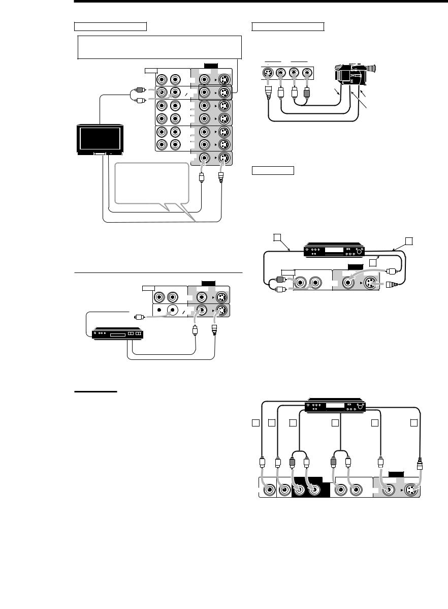
TV and/or DBS tuner
When connecting the TV to the AUDIO jacks (TV SOUND/ DBS), DO NOT connect the TV’s video output to these video input terminals.
Video camera
The VIDEO input terminals on the front panel are convenient when connecting and disconnecting the equipment frequently.
|
|
|
|
S-VIDEO |
VIDEO |
|
|
|
|
VIDEO |
VIDEO |
L—AUDIO—R |
|
|
|
|
|
|
|
|
AUDIO |
RIGHT |
LEFT |
VIDEO |
S-VIDEO |
|
|
|
|
DVD |
|
|
|
To audio |
|
|
FRONT |
|
|
|
|
|
|
TV SOUND |
|
|
|
output |
|
|
DBS |
|
|
|
|
|
OUT |
|
To audio |
(REC) |
|
VCR1 |
||
output |
||
IN |
||
|
(PLAY) |
OUT (REC)
VCR2
IN (PLAY)
TV
MONITOR
OUT
To S-video output
To composite video output
Connect the TV to the MONITOR OUT terminal to view the playback picture from the other connected video components.
To composite video input
To S-video input
DVD player
•When you connect the DVD player with stereo output jacks:
ÅTo front left/right channel audio output (or to audio mixed
output if necessary)
ı To composite video output Ç To S-video output
Note: |
A |
Use a TV of PALor multi-color system.
DVD player
C
DVD |
|
|
|
|
|
VIDEO |
B |
|
|
|
|
|
|
|
|
|
|
AUDIO RIGHT |
LEFT |
VIDEO |
S-VIDEO |
|
|
VIDEO |
|
|
DVD |
|
AUDIO RIGHT |
LEFT |
VIDEO |
S-VIDEO |
|
FRONT |
|
To audio output 


DBS tuner
DVD |
TV SOUND |
|
DBS |
||
FRONT |
||
|
TV SOUND
DBS
• When you connect the DVD player with its analog discrete output (5.1 CH reproduction) jacks:
DBS
To composite video output
To S-video output
Å To subwoofer output
ı To center channel audio output
Ç To rear left/right channel audio output Î To front left/right channel audio output ‰ To composite video output
Ï To S-video output
Note:
When connecting the DBS tuner to the TV SOUND/DBS jacks, change the source name, which will be shown on the display when selected as the source, to “DBS.” See page 16 for details.
A B C
DVD player
DVD |
D |
E |
F |
|
|
|
|
|
|
VIDEO |
|
|
SUB |
CENTER |
RIGHT |
LEFT |
AUDIO RIGHT |
LEFT |
VIDEO |
S-VIDEO |
|
WOOFER |
||||||||
|
|
|
|
|
|
|
||
DVD |
|
|
|
|
|
DVD |
|
|
|
|
|
|
REAR |
|
FRONT |
|
7

 Digital Connections
This receiver is equipped with four DIGITAL IN terminals — one digital coaxial terminal and three digital optical terminals, and one DIGITAL OUT terminal.
IMPORTANT:
•When connecting the DVD player, digital TV broadcast tuner or DBS tuner using the digital terminals, you also need to connect it to the video terminal on the rear. Without connecting it to the video terminal, you can view no playback picture.
•After connecting the components using the DIGITAL IN terminals, set the following correctly if necessary.
–Set the digital input (DIGITAL IN) terminal setting correctly. For details, see “Digital Input (DIGITAL IN) Terminal Setting” on page 19.
–Select the digital input mode correctly. For details, see “Selecting the Analog or Digital Input Mode” on page 20.
Digital input terminals
You can connect any digital equipment as follow.
Digital TV
DBS tuner
DBS
Notes:
•When shipped from the factory, the DIGITAL IN terminals have been set for use with the following components.
–DIGITAL 1 (coaxial): For DVD player
–DIGITAL 2 (optical): For CD player
–DIGITAL 3 (optical): For digital TV broadcast tuner
–DIGITAL 4 (optical): For CD recorder
•When you want to operate the CD player, CD recorder, or MD recorder using the COMPU LINK remote control system, connect the target component also as described in “Analog Connections”
(see page 6).
Digital output terminal
|
|
CD recorder |
|
|
MD recorder |
||
|
|
|
|
|
|
|
|
|
|
|
|
|
|
|
|
Digital optical cable (not supplied) between digital optical terminals
DVD player
DVD |
CD recorder
CD player
MD recorder
When the digital recording equipment such as an MD recorder and CD recorder has a digital optical input terminal, connecting it to the DIGITAL OUT terminal enables you to perform digital-to- digital recording.
PCM/DOLBYDIGITAL /DTS
DIGITALOUT
Digital coaxial cable (not supplied) between digital coaxial terminals
Digital optical cable (not supplied) between digital optical terminals
When the component has a digital coaxial output terminal, connect it to the DIGITAL 1 (DVD) terminal, using the digital coaxial cable (not supplied).
When the component has a digital optical output terminal, connect it to the DIGITAL 2 (CD), DIGITAL 3 (TV) or DIGITAL 4 (CDR) terminal, using the digital optical cable (not supplied).
Before connecting a digital optical cable, unplug the protective plug.
DIGITALIN
DIGITAL1(DVD)
DIGITAL2(CD)
DIGITAL3(TV)
DIGITAL4(CDR)
Note:
The digital signal format output through the DIGITAL OUT terminal is the same as that of the input signal. This means that when the DTS
Digital Surround signals are input, the DTS Digital Surround signals are output.
8


 USB Connection
This receiver is equipped with a USB terminal on the front panel. You can connect your PC to this terminal and enjoy sound reproduced through your PC.
When you connect your PC for the first time, follow the procedure below.
• Remember you cannot send any signal or data to your PC from this receiver.
IMPORTANT
•Check if your PC equipped with the CD-ROM drive is running on WindowsR 98*, WindowsR Me*, or WindowsR 2000* and prepare its CD-ROM.
•Check your PC’s BIOS setting — whether USB is available, and whether USB IRQ is set to “AUTO” or to available IRQ number.
How to install the USB drivers
The following procedure is described using the English version of WindowsR 98. If your PC is running on a different version of Windows, the screens shown on your PC’s monitor will differ from the ones used in the following procedure.
1.Turn on your PC and start running WindowsR 98, WindowsR Me or WindowsR 2000.
If the PC has been turned on, quit all the applications now running.
2.Turn on the receiver, and press USB AUDIO on the front panel or USB on the remote control.
The lamp on the USB AUDIO button lights up.
3.Connect the receiver to the PC using a USB cable (not supplied).
Your PC automatically recognizes this connection, and shows the following screen on the monitor.
USB AUDIO |
|
|
|
|
VIDEO |
|
|
||||
|
|
|
|
S-VIDEO |
VIDEO |
L—AUDIO—R |
|||||
|
|
|
|
|
|
|
|
|
|
|
|
|
|
|
|
|
|
|
|
|
|
|
|
|
|
|
|
|
|
|
|
|
|
|
|
|
|
|
|
|
|
|
|
|
|
|
|
|
|
|
|
|
|
|
|
|
|
|
|
|
|
|
|
|
|
|
|
|
|
|
|
|
|
|
|
|
|
|
|
|
|
|
|
PC
USB cable
4.Install the USB drivers following the instructions on the PC’s monitor.
5.Check if the drivers are correctly installed.
1.Open the Control Panel on your PC: Select [Start] = [Settings] =[Control Panel]
2.Select [System], then [Device Manager] and click [Sound, video and game controllers] and [Universal Serial Bus controllers.]
The following window appears, and you can check whether the drivers are installed.
Note:
The items shown on the PC’s monitor differ depending on your PC settings.
6.Change the PC audio setting.
1.If you have closed Control Panel, open it again: Select [Start] =[Settings] =[Control Panel]
2.Click [Multimedia], then select “USB Audio Device [1]” for “Playback” of “Audio,” and close the window.
To play back a CD from CD-ROM drive on PC, click [Multimedia], [CD Music] then check [Enable digital CD audio for this CD-ROM device].
Now PC is ready for playback through the USB connection.
After installation is completed, you can use your PC as the playback source. The PC automatically recognizes the receiver whenever a USB cable is connected between the PC and the receiver while the receiver is turned on.
• When not using the PC as the playback source, disconnect the USB cable.
To play back sounds on the PC, refer to the manuals supplied with the sound reproduction application installed in the PC.
Notes:
•DO NOT turn off the receiver or disconnect the USB cable while installing the drivers and for a several seconds each time your PC is recognizing the receiver.
•Use a full speed USB cable (revision 1.0).
•If your PC does not recognize the receiver, disconnect the USB cable and connect it again. If this does not work, restart Windows.
•The drivers installed can be recognized only when the USB cable is connected between the receiver and your PC.
•The sound may not be played back correctly — interrupted or degraded — due to your PC settings and PC specifications.
•When you don't use the USB AUDIO terminal, keep the terminal cover attached.
*Microsoft R, WindowsR 98, WindowsR Me and WindowsR 2000 are registered trademarks of Microsoft Corporation.
9
Connecting the Power Cord
Before plugging the receiver into an AC outlet, make sure that all connections have been made.
Plug the power cord into an AC outlet.
Keep the power cord away from the connecting cables and the antenna. The power cord may cause noise or screen interference. We recommend that you use a coaxial cable to connect the antenna, since it is well-shielded against interference.
Note:
The preset settings such as preset channels and sound adjustment may be erased in a few days in the following cases:
–When you unplug the power cord.
–When a power failure occurs.
CAUTIONS:
•Do not touch the power cord with wet hands.
•Do not pull on the power cord to unplug the cord. When unplugging the cord, always grasp the plug so as not to damage the cord.
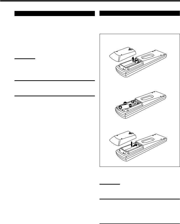
Putting Batteries in the Remote Control
Before using the remote control, put two supplied batteries first. When using the remote control, aim the remote control directly at the remote sensor on the receiver.
1.On the back of the remote control, remove the battery cover.
2.Insert batteries. Make sure to match the polarity: (+) to (+) and (–) to (–).
R6P(SUM-3)/AA(15F)
3. Replace the cover.
If the range or effectiveness of the remote control decreases, replace the batteries. Use two R6P(SUM-3)/AA(15F) type dry-cell batteries.
Note:
After replacing the batteries, set the manufacturers’ codes again (see page 54).
CAUTION:
Follow these precautions to avoid leaking or cracking cells:
•Place batteries in the remote control so they match the polarity:
(+) to (+) and (–) to (–).
•Use the correct type of batteries. Batteries that look similar may differ in voltage.
•Always replace both batteries at the same time.
•Do not expose batteries to heat or flame.
10

 Basic Operations
The following operations are commonly used when you play any sound source. You can also use on-screen menus for most of the operations mentioned in this section. For details, see page 40.
Before using the remote control

 How to confirm the remote control operation mode
The display window on the remote control shows following information for about 10 seconds when you press certain buttons on the remote control, so that you can confirm which operation you do.
Pressing one of the source selecting buttons, the source name selected appears on the display.
Buttons |
Indications |
|
FM/AM |
TUNER |
|
CD |
CD |
|
PHONO |
PHONO |
|
TAPE/MD |
TAPE |
Ex.: When you |
DVD or DVD MULTI |
DVD |
press CD. |
CDR |
CDR |
|
USB |
USB |
|
TV/DBS |
TV |
|
VCR 1 |
VCR1 |
|
VCR 2 |
VCR2 |
|
VIDEO |
VIDEO |
|
Pressing SOUND before you adjust the sound effect, “SOUND” appears on the display.
Pressing TEXT DISPLAY or MENU before you use on-screen menu or TEXT COMPU LINK, “MENU” appears on the display (see pages 40 and 47).
Pressing CONTROL or CATV/DBS |
|
|
CONTROL before you operate an audio or |
|
|
video equipment connected to the receiver, |
Ex.: When you |
|
the remote control operation mode selected |
||
press CATV/ |
||
appears on the display (see pages 51 and 54). |
||
DBS CONTROL. |
||
|
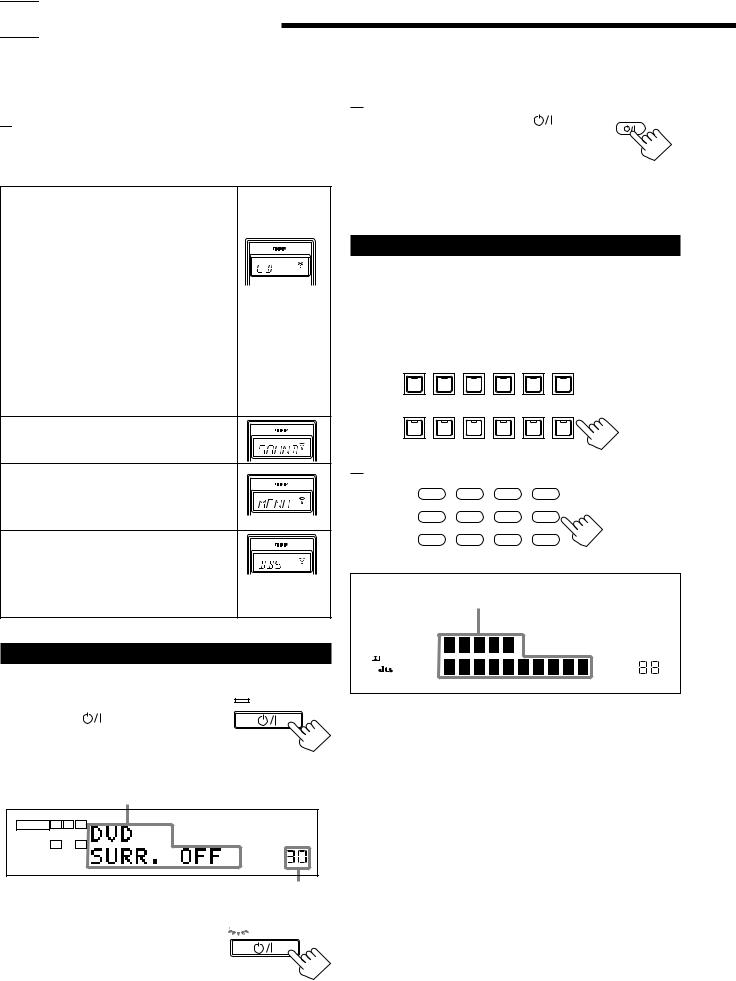
Turning the Power On and Off (Standby)
On the front panel:
From the remote control:
To turn on the power, press AUDIO |
. |
AUDIO |
|
The STANDBY lamp on the front panel goes off.
The name of the current source and Surround/
DSP mode appear on the display.
To turn off the power (into standby mode), press AUDIO  again. The STANDBY lamp on the front panel lights up.
Selecting the Source to Play
Press one of the source selecting buttons.
The lamp on the front panel button for selected source lights up.
• The selected source name and Surround/DSP mode also appear on the display.
On the front panel:
DVD MULTI |
DVD |
VCR 1 |
VCR 2 |
VIDEO |
TV SOUND/DBS |
|
|
|
|
|
SOURCE NAME |
PHONO |
CD |
CDR |
TAPE / MD |
USB AUDIO |
FM / AM |
SOURCE NAME
From the remote control:
DVD |
DVD MUILTI |
CD |
FM/AM |
TV/DBS |
VIDEO |
CDR |
PHONO |
VCR 1 |
VCR 2 |
TAPE/MD |
USB |
Selected source name and current
Surround/DSP mode appear
|
|
|
|
|
DGTL AUTO |
DVD MULTI PRO LOGIC |
AUTO MUTING TUNED |
STEREO RDS EON |
|
ANALOG |
L |
C |
R |
|
DSP 3D–PHONIC MIDNIGHT MODE |
TA NEWS INFO |
|
|
|
|
|
LFE |
|
|||
|
LINEAR PCM |
SUBWFR |
|
HEADPHONE |
DIGITAL EQ INPUT ATT |
ONETOUCH OPERATION |
||
|
|
|
|
|
|
|||
|
|
LS |
S |
RS |
|
|
|
|
|
DIGITAL |
|
|
|
|
|
|
|
|
SPEAKERS |
|
|
SLEEP VOLUME |
||||
|
|
|
|
|||||
|
|
1 2 |
|
|
|
|
||
|
|
|
|
|
|
|
|
|
To turn on the power, press |
STANDBY |
||
|
|||
STANDBY/ON |
. |
DVD MULTI |
|
The STANDBY lamp goes off. The name of the |
|||
STANDBY/ON |
|||
current source and Surround/DSP mode appear |
|
||
on the display. |
|
|
|
Current source name and |
DVD |
||
Surround/DSP mode appear |
VCR 1 |
||
ANALOG |
L |
R |
VCR 2 |
|
|
|
|
|
SPEAKERS |
VIDEO |
|
|
1 |
VOLUME |
|
Current volume level appears
To turn off the power (into standby mode), 


 STANDBY press STANDBY/ON
  again.
The STANDBY lamp lights up. A small
STANDBY/ON
amount of power is consumed in standby mode. To turn the power off completely, unplug the AC power cord.
TV (SOUND)/DBS PHONO *
CD *
CDR * TAPE/MD * USB (AUDIO) *
FM/AM *
Select the DVD player for viewing the digital video disc using the analog discrete output mode (5.1 CH reproduction).
To enjoy the DVD MULTI playback, see page 39. Select the DVD player.
Select the video component connected to the VCR 1 terminals.
Select the video component connected to the VCR 2 terminals.
Select video component connected to the VIDEO terminals.
Select TV sounds (or the DBS tuner). Select the turntable.
Select the CD player. Select the CD recorder.
Select the cassette deck (or the MD recorder). Select the personal computer (PC) connected to the USB terminal.
Select an FM or AM (MW/LW) broadcast.
• Each time you press the button, the band alternates between FM and AM (MW/LW).
11
Notes:
•When connecting an MD recorder (to the TAPE/MD jacks), and a DBS tuner (to the TV SOUND/DBS jacks), change the source names shown on the display. For details, see page 16.
•When you press one of the source selecting buttons on the remote control marked with an asterisk (*), the receiver automatically turns on.
Signal and speaker indicators on the display
The signal indicators light up in the following cases:
•Only the indicators for the incoming signals light up.
•When analog input is selected, “L” and “R” always light up.
•When “DVD MULTI” is selected as the source, “L,” “C,” “R,”
“LFE,” “LS” and “RS” light up.
The speaker indicators light up only —:
The frames of “C,” “LS,” and “RS” light up, when the corresponding speaker is set to “LARGE” or “SMALL”.
Signal indicators light up in |
Speaker indicators light up |
||||
red: |
|
|
in white: |
|
|
L |
C |
R |
L |
C |
R |
SUBWFR |
LFE |
SUBWFR |
LFE |
||
LS |
S |
RS |
LS |
S |
RS |
L: • When digital input is selected: Lights up when the left channel signal comes in.
• When analog input is selected: Always lights up.
R: • When digital input is selected: Lights up when the right channel signal comes in.
• When analog input is selected: Always lights up.
C: Lights up when the center channel signal comes in. LS: Lights up when the left rear channel signal comes in. RS: Lights up when the right rear channel signal comes in.
S: Lights up when the monaural rear channel signal comes in. LFE: Lights up when the LFE channel signal comes in.
Note:
When “SUBWOOFER” is set to “YES,” SUBWFR lights up (see page
17).
Selecting different sources for picture and sound
You can watch picture from a video component while listening to sound from another component.
Press one of the audio source selecting buttons — PHONO, CD, CDR, TAPE/MD, USB (AUDIO), FM/AM — while viewing the picture from a video component such as the VCR or DVD player,
etc.
The lamp on the front panel button for selected source lights up.
On the front panel:
DVD MULTI |
DVD |
VCR 1 |
VCR 2 |
VIDEO |
TV SOUND/DBS |
|
|
|
|
|
SOURCE NAME |
PHONO |
CD |
CDR |
TAPE / MD |
USB AUDIO |
FM / AM |
SOURCE NAME
From the remote control:
DVD |
DVD MUILTI |
CD |
FM/AM |
TV/DBS |
VIDEO |
CDR |
PHONO |
VCR 1 |
VCR 2 |
TAPE/MD |
USB |
Note:
Once you have selected a video source, pictures of the selected source are sent to the TV until you select another video source.
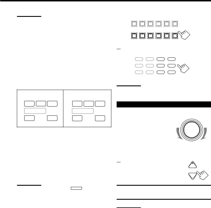
Adjusting the Volume
On the front panel:
To increase the volume, turn MASTER VOLUME clockwise.
To decrease the volume, turn it counterclockwise.
•When you turn MASTER VOLUME rapidly, the volume level also changes rapidly.
•When you turn MASTER VOLUME slowly, the volume level also changes slowly.
From the remote control:
To increase the volume, press VOLUME +. To decrease the volume, press VOLUME –.
MASTER VOLUME
+
VOLUME
−
CAUTION:
Always set the volume to the minimum before starting any source. If the volume is set at its high level, the sudden blast of sound energy can permanently damage your hearing and/or ruin your speakers.
Notes:
•The volume level can be adjusted within the range of “0” (minimum) to “90” (maximum).
•If you set One Touch Operation to “ON” (see page 22), you do not have to adjust the volume level each time you change the source. It is automatically set to the stored level.
12
Selecting the Front Speakers
On the front panel ONLY:
When you have connected two pairs of the front speakers, you can select which to use.
To use the speakers connected to the |
SPEAKERS ON/OFF |
FRONT SPEAKERS 1 terminals, press |
1 |
SPEAKERS ON/OFF 1 so that SPEAKERS 1 |
|
|
indicator lights up on the display. Make sure |
2 |
|
that the SPEAKERS 2 is not lit on the display. |
||
|
To use the speakers connected to the FRONT SPEAKERS 2 terminals, press SPEAKERS ON/OFF 2 so that SPEAKERS 2 indicator lights up on the display. Make sure that the SPEAKERS 1 is not lit on the display.
To use both sets of the speakers, press SPEAKERS ON/OFF 1 and 2 so that the SPEAKERS 1 and SPEAKERS 2 indicators light up on the display.
To use neither sets of the speakers, press SPEAKERS ON/OFF 1 and 2 so that the SPEAKERS 1 and SPEAKERS 2 indicators disappear from the display.
The HEADPHONE indicator lights up and “HEADPHONE” appears on the display.
•Activating the speaker turns on the Surround and DSP modes previously selected.
•Listening only with headphones:
You can listen with the headphones without deactivating both pairs of speakers by connecting a pair of headphones to the PHONES jack on the front panel. If you want to use a pair of headphones without outputting sounds from the front speakers, you must turn off both pairs of the front speakers as mentioned above.
Notes:
•If you use any of the Surround and DSP modes using the center or rear speakers with both front speakers activated, the speakers connected to the FRONT SPEAKERS 2 terminals are deactivated.
•When you use HEADPHONE DSP mode, you can enjoy spacious stereo effect (see page 29).
CAUTION:
Be sure to turn down the volume before connecting or putting on headphones, as high volume can damage both the headphones and your hearing.
Muting the Sound
From the remote control ONLY: |
|
|
|
|
|
Press MUTING to mute the sound through all |
MUTING |
|
speakers and headphones connected. |
|
|
“MUTING” appears on the display and the volume turns off (the volume level indicator goes off).
To restore the sound, press MUTING again so that “MUTING OFF” appears on the display.
• Turning MASTER VOLUME on the front panel or pressing VOLUME +/– on the remote control also restores the sound.
Listening at Night — Midnight Mode
Using the midnight mode, you can enjoy a powerful sound at night even at a low volume level.
• You can do this setting for each source.
Press MIDNIGHT MODE to select the midnight mode.
MIDNIGHT MODE |
MIDNIGHT |
|
MODE |
On the front panel From the remote control
• Each time you press the button, the midnight mode changes as follow:
 MIDNIGHT 1
 MIDNIGHT 2
NORMAL
MIDNIGHT 1: Select this when you want to compress the dynamic range a little.
The MIDNIGHT MODE indicator lights up on the display.
MIDNIGHT 2: Select this when you want to compress the dynamic range fully. (Useful at midnight.)
The MIDNIGHT MODE indicator lights up on the display.
NORMAL: Select this when you want to enjoy sound with its full dynamic range. (No effect applied.)
The MIDNIGHT MODE indicator goes off from the display.
Notes:
•When the line direct function is turned on, the midnight mode is canceled temporarily.
•The midnight mode is not valid for the DVD MULTI playback mode.
13
Activating the Subwoofer Sound |
Attenuating the Input Signal |
You can cancel the subwoofer sound even though you have connected a subwoofer and have set “SUBWOOFER” to “YES”
(see page 17). This is useful when enjoying surround sound at night.
On the front panel ONLY: |
|
Press SUBWOOFER OUT ON/OFF to |
SUBWOOFER OUT ON/OFF |
cancel the subwoofer sound output. |
|
Each time you press the button, the subwoofer sound output is deactivated (“SUBWFR OFF”) or activated (“SUBWFR ON”).
–Select “SUBWFR OFF” to deactivate the subwoofer sound output.
–Select “SUBWFR ON” to activate it.
Note:
You cannot select “SUBWFR OFF” even though “SUBWOOFER” is set to “YES,” when “SMALL” is selected for the front speakers (see page 17.)
When the input level of the playing source is too high, the sounds will be distorted. If this happens, you need to attenuate the input signal level to prevent the sound distortion.
• You can do this setting for each source.
On the front panel ONLY: |
|
|
Press and hold INPUT ATT (INPUT |
INPUT |
|
ANALOG/DIGITAL) so that the INPUT ATT |
ANALOG/DIGITAL |
|
|
||
indicator lights up on the display. |
INPUT ATT |
|
• Each time you press and hold the button, the |
||
|
||
input attenuator mode turns on (“ATT ON”) or |
|
|
off (“NORMAL”). |
|
Notes:
•This function is available only for the sources connected using the analog terminals.
•When selecting “DVD MULTI” as the source, this effect does not work.
Reinforcing the Bass
You can boost the bass level.
• You can do this setting for each source.
On the front panel: |
|
Press BASS BOOST to select the bass boost |
BASS BOOST |
function. |
|
The BASS BOOST lamp on the front panel button lights up.
• Each time you press the button, the bass boost function turns on (“BOOST ON”) and off (“BOOST OFF”).
–Select “BOOST ON” to activate the bass boost function. The BASS BOOST lamp on the front panel button lights up.
–Select “BOOST OFF” to cancel it.
The BASS BOOST lamp on the front panel button goes off.
From the remote control:
SOUND
1. Press SOUND.
The 10 keys are activated for sound adjustments.
2. Press BASS BOOST to select the bass |
BASS |
BOOST |
|
boost function. |
1 |
|
The BASS BOOST lamp on the front panel button lights up.
• Each time you press the button, the bass boost function turns on (“BOOST ON”) and off (“BOOST OFF”).
–Select “BOOST ON” to activate the bass boost function. The BASS BOOST lamp on the front panel button lights up.
–Select “BOOST OFF” to cancel it.
The BASS BOOST lamp on the front panel button goes off.
Note:
This function does not affect the sounds outputting from the rear speakers.
Selecting the Line Direct Function
You can enjoy the sound closer to original source by skipping the sound adjustments such as digital equalization and midnight mode. Only the volume level and bass boost function are adjustable when the line direct function is turned on.
• You can do this setting for each source.
Press LINE DIRECT.
The LINE DIRECT lamp on the front panel button lights up.
LINE DIRECT LINEDIRECT
On the front panel From the remote control
• Each time you press the button, the line direct function turns on (“DIRECT ON”) and off (“DIRECT OFF”).
–Select “DIRECT ON” to activate the line direct function. The LINE DIRECT lamp on the front panel button lights up.
–Select “DIRECT OFF” to cancel it.
The LINE DIRECT lamp on the front panel button goes off.
Notes:
•If you turn on the line direct function while using the Surround and
DSP modes, the effect changes as follows:
Input |
Mode |
Surround |
DSP |
|
|||
|
|
|
|
Analog |
Not valid |
Not valid |
|
Digital |
|
Valid |
Not valid |
•Turning off the line direct function activates the sound adjustments previously selected such as the digital equalization and midnight mode.
14
Adjusting the Equalization Patterns
You can adjust equalization to your preference.
• You can do this setting for each source.
Before you start, remember....
• There is a time limit in doing the following steps. If the setting is canceled before you finish, start from step 1 again.
On the front panel:
1. Press DIGITAL EQ (Equalization) |
DIGITAL |
LEV |
repeatedly to select the frequency. |
EQ |
ADJU |
|
|
|
• Each time you press the button, the frequency |
|
|
|
|
|
with its current level changes as follows: |
|
|
|
|
EQ63Hz |
|
EQ250Hz |
|
|
EQ1kHz |
|
|
|
and its level |
|
and its level |
|
|
and its level |
|
|
|
EQ16kHZ |
EQ4kHz |
|
|
|
||||
|
|
|
||||||
and its level |
and its level |
|
|
|||||
2. Press CONTROL UP 5/DOWN |
|
CONTROL |
||||||
DOWN UP
repeatedly to adjust the frequency level.
The frequency level changes by 2 dB from –8 dB to +8 dB. The DIGITAL EQ indicator lights up on the display.
3. Repeat Steps 1 and 2 to adjust the other frequency level.
To flat the equalization pattern,
set all the frequency levels to “0” in step 2. The DIGITAL EQ
indicator goes off from the display.
From the remote control:
1.Press SOUND.
The 10 keys are activated for sound adjustments.
2.Press DIGITAL EQ (Equalization) repeatedly to select the frequency you want.
“EQ” appears on the remote control display window.
SOUND
DIGITALEQ
10
RETURN
• Each time you press the button, the frequency with its current level changes as follows:
 EQ63Hz
  EQ250Hz
  EQ1kHz
and its level and its level and its level
EQ16kHZ |
EQ4kHz |
and its level |
and its level |
3.Press LEVEL + or − repeatedly to adjust the frequency level.
The frequency level changes by 2 dB from –8 dB to +8 dB. The DIGITAL EQ indicator lights up on the display.
4.Repeat steps 2 and 3 to adjust the other frequency level.
To flat the equalization pattern,
+ BAL L
CH/ LEVEL
− BAL R
set all the frequency levels to “0” in step 3. The DIGITAL EQ indicator goes off from the display.
Notes:
•When the line direct function is turned on, the digital equalization cannot be adjusted.
•The digital equalization affects the front speaker sounds only.
Using the Sleep Timer
Using the Sleep Timer, you can fall asleep to music and know the receiver will turn off by itself rather than play all night.
From the remote control ONLY:
SLEEP
Press SLEEP repeatedly.
The SLEEP indicator lights up on the display, and the shut-off time changes as follows (in minutes):
 10
10  20
20  30
30  40
40  50
50  60
60  70
70  80
80  90
90
0 (Canceled)
When the shut-off time comes
The receiver turns off automatically.
To check or change the time remaining until the shut-off time
Press SLEEP once.
The remaining time until the shut-off time appears in minutes.
• To change the shut-off time, press SLEEP repeatedly.
To cancel the Sleep Timer
Press SLEEP repeatedly until “SLEEP 0min” appears on the display. (The SLEEP indicator goes off.)
• Turning off the power also cancels the Sleep Timer.
Recording a Source
For analog-to-analog recording
You can record any analog source through the receiver to —
•the cassette deck (or MD recorder) connected to the TAPE/MD jacks,
•the VCRs connected to the VCR 1 and VCR 2 jacks, and
•the CD recorder connected to the CDR jacks
— at the same time.
For digital-to-digital recording
You can record the currently selected digital input source through the receiver to a digital recording device connected to the DIGITAL OUT terminal.
Notes:
•Analog-to-digital and digital-to-analog recordings are not possible.
•The output volume level, midnight mode (see page 13), bass boost
(see page 14), digital equalization (see the left), Surround modes and DSP modes (see page 28) cannot affect the recording.
•The test tone signal (see page 31) does not come out through the
DIGITAL OUT terminal.
15

 Basic Settings
Some of the following settings are required after connecting and positioning your speakers in your listening room, while others will make operations easier. You can also use on-screen menus for most of the operations mentioned in this section. For details, see page 40.
Adjusting the Front Speaker Output
Balance
If the sounds you hear from the front right and left speakers are unequal, you can adjust the speaker output balance.
• You can do this setting for each source.
Before you start, remember....
• There is a time limit in doing the following steps. If the setting is canceled before you finish, start from step 1 again.
On the front panel:
1. |
Press LEVEL ADJUST repeatedly |
|
|
LEVEL |
|
L |
|||
|
until “BAL– (with current |
|
|
ADJUST |
|
|
|
|
|
|
|
|
|
|
|
setting)” appears on the display. |
|
|
|
|
|
|
|
|
2. |
Press CONTROL UP 5/DOWN |
|
CONTROL |
|
|
|
DOWN UP |
||
to adjust the balance.
•Pressing CONTROL UP 5decreases the left channel output (from CENTER to L–21).
•Pressing CONTROL DOWN decreases the right channel output (from CENTER to R–21).
From the remote control:
1. Press SOUND. |
SOUND |
|
The 10 keys are activated for sound adjustments.
2. Press L/R BAL.
“L/R” appears on the remote control display window.
3.Press BAL L or BAL R to adjust the balance.
•Pressing BAL L decreases the right channel output (from CENTER to R–21).
•Pressing BAL R decreases the left channel output (from CENTER to L–21).
L/R BAL
8
+ BAL L
CH/ LEVEL
− BAL R
Changing the Source Name
When you have connected an MD recorder to the TAPE/MD jacks or the DBS tuner to the TV SOUND/DBS jacks on the rear panel, change the source name which will be shown on the display when you select the MD recorder or DBS tuner as the source.
On the front panel ONLY:
When changing the source name from “TAPE” to “MD”:
• Press and hold SOURCE NAME (TAPE/MD) until “ASSGN. MD” appears on the display.
When changing the source name from “TV” to “DBS”:
• Press and hold SOURCE NAME (TV SOUND/DBS) until “ASSGN. DBS” appears on the display.
To change the source name to “TAPE” or “TV,” repeat the same procedure above — press and hold SOURCE NAME (TAPE/MD) to select “TAPE,” or press and hold SOURCE NAME (TV SOUND/DBS) to select “TV.”
Note:
Without changing the source name, you can still use the connected components. However, there may be some inconvenience.
–“TAPE” or “TV” will appear on the display when you select the MD recorder or DBS tuner.
–You cannot use the digital input (see page 19) for the MD recorder.
–You cannot use the COMPU LINK remote control system (see page
45) to operate the MD recorder.
16
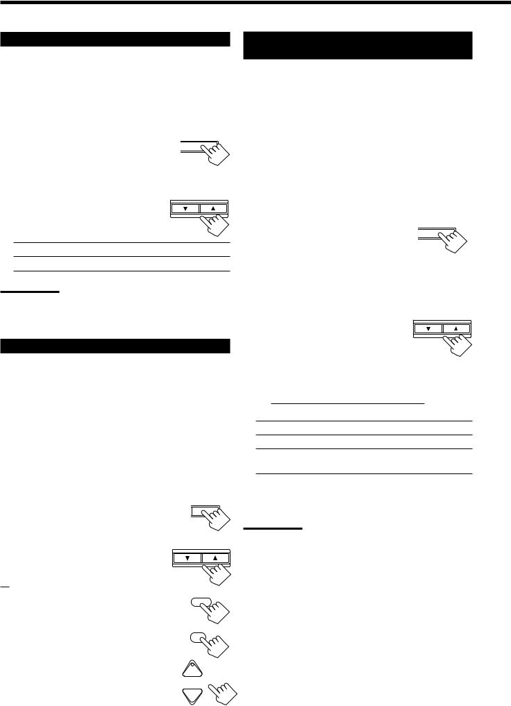
Setting the Subwoofer Information
Register whether you have connected a subwoofer or not.
Before you start, remember....
• There is a time limit in doing the following steps. If the setting is canceled before you finish, start from step 1 again.
On the front panel ONLY:
1. |
Press SETTING repeatedly until |
|
CT |
SETTING |
|
“SUBWOOFER” appears on the |
|
|
|
|
|
|
|
|
|
display. |
|
|
|
|
|
|
|
|
|
The display changes to show the current setting. |
|
|
|
2. |
Press CONTROL UP 5/DOWN |
|
CONTROL |
|
DOWN UP |
||||
to select “YES” or “NO.”
• Each time you press the button, the display alternates between “YES” and “NO.”
YES: Select this when a subwoofer is connected.
NO: Select this when no subwoofer is used.
Note:
You cannot use SUBWOOFER OUT ON/OFF on the front panel (see page 14) and adjust the subwoofer output level (see below) when “SUBWOOFER” is set to “NO.”
Adjusting the Subwoofer Output Level
You can adjust the subwoofer output level if you have selected “YES” for the “SUBWOOFER” (see above).
Once it has been adjusted, the receiver memorizes the adjustment.
• You can do this setting for each source.
Before you start, remember....
•There is a time limit in doing the following steps. If the setting is canceled before you finish, start from step 1 again.
•When the front speakers are all deactivated, the subwoofer level cannot be adjusted.
On the front panel:
1. Press LEVEL ADJUST repeatedly until “SUBWFR” appears on the display.
The display changes to show the current setting.
2.Press CONTROL UP 5/DOWN to adjust the subwoofer output level (from –20 dB to +10 dB).
From the remote control:
AL LEVEL ADJUST
CONTROL
DOWN UP
1. Press SOUND. |
SOUND |
|
The 10 keys are activated for sound adjustments.
2. |
Press SUBWFR . |
SUBWFR |
|
“S-WFR” appears on the remote control display |
7/P |
|
|
|
|
window. |
+ BAL L |
3. |
Press LEVEL +/– to adjust the |
|
|
subwoofer output level (from –20 dBCH/ LEVEL |
|
|
to +10 dB). |
− BAL R |
Setting the Speakers for a Surround
Field
To obtain the best possible surround sound of the Surround and DSP modes, you have to register the information about the speakers arrangement after all connections are completed.
Before you start, remember....
• There is a time limit in doing the following steps. If the setting is canceled before you finish, start from step 1 again.
Front, Center, and Rear Speaker Setting
Register the sizes of all the connected speakers.
• When you change your speakers, you need to register the information about the speakers again.
On the front panel ONLY:
1. Press SETTING repeatedly until |
CT |
SETTING |
|
|
|
“FRONT SPK” (Front Speaker), |
|
|
|
|
|
“CTR SPK” (Center Speaker) or |
|
|
|
|
|
“REAR SPK” (Rear Speaker) |
|
|
appears on the display. |
|
|
The display changes to show the current setting.
2. Press CONTROL UP 5/DOWN CONTROL
to select the appropriate item |
DOWN UP |
|
|
about the speaker selected in the |
|
above step. |
|
• Each time you press the button, the display changes to show the following:

 LARGE
LARGE
 SMALL
SMALL
 NONE
NONE 

LARGE: Select this when the speaker size is relatively large.
SMALL: Select this when the speaker size is relatively small.
NONE: Select this when you have not connected a speaker. (Not selectable for the front speakers)
3.Repeat steps 1 and 2 to select the appropriate items for the other speakers.
Notes:
•Keep the following comment in mind as reference when adjusting.
–If the size of the cone speaker unit built in your speaker is greater than 12 cm, select “LARGE,” and if it is smaller than 12 cm, select “SMALL.”
•If you have selected “NO” for the subwoofer setting, you can only select “LARGE” for the front speaker setting.
•If you have selected “SMALL” for the front speaker setting, you cannot select “LARGE” for the center and rear speaker settings.
17
Loading...