


AUDIO/VIDEO CONTROL RECEIVER
RX-8020VBK
A/V CONTROL RECEIVER
CATV/DBS |
VCR1 |
TV |
AUDIO |
|
|
|
|
|
|
|
|
|
|
|
|
|
|
DVD |
DVD MULTI |
CD |
FM/AM |
|
|
|
|
|
|
|
|
|
|
|
|
|
|
TV/DBS |
|
VIDEO |
CDR |
PHONO |
|
|
|
|
|
|
|
|
|
|
|
|
|
VCR1 |
|
VCR 2 |
TAPE/MD |
USB |
|
|
|
|
|
|
|
|
|
|
|
|
|
SURROUND |
|
DSP |
SURR/DSP ANALOG/DIGITAL |
|
|
|
|
|
|
|
|
|
|
|
|
|
|
|
|
|
OFF |
INPUT |
|
|
|
|
|
RX-8020V AUDIO/VIDEO CONTROL RECEIVER |
|
|
|||||
ANALOG |
|
BASS |
|
|
|
|
|
|
|
|
|
||||||
|
FRONT•L |
FRONT•R |
|
|
|
|
|
|
|
|
|
|
|
|
|
||
DIRECT |
|
BOOST |
|
|
|
|
|
|
|
|
|
|
|
|
|
||
|
|
1 |
2 |
3 |
|
|
|
|
|
|
|
|
|
|
|
|
|
|
|
|
MENU |
FM/AM TUNING |
FM/AM PRESET |
|
FM MODE |
|
|
|
|
|
|
|
|
|
|
SOUND |
|
TEST |
CENTER |
SUBWFR |
|
|
|
|
|
|
|
|
|
|
|
|
|
|
|
4 |
5 |
6 |
STANDBY |
|
|
|
|
|
|
|
|
|
|
|
MASTER VOLUME |
|
|
|
ENTER |
|
|
|
MEMORY |
|
|
|
|
|
|
|
|
||
DIMMER |
|
|
SURR•L |
SURR•R |
|
|
|
|
|
|
|
|
|
|
|
|
|
|
|
|
|
|
|
|
|
|
|
|
|
|
|
|
|||
|
|
7/P |
8 |
9 |
STANDBY/ON |
|
|
|
|
|
|
|
|
|
|
|
|
MUTING |
DIGITALEQ SBACK•L SBACK•R |
|
|
|
|
|
|
|
|
|
|
|
|
||||
|
|
|
|
|
|
|
|
|
|
|
|
|
|||||
|
|
10 |
0 |
+10 |
|
|
|
|
|
|
|
|
|
|
|
|
|
|
|
RETURN |
FMMODE |
100+ |
SPEAKERS ON/OFF |
|
|
|
|
|
|
|
|
|
|
|
|
CATV/DBS |
|
|
|
|
1 |
|
|
|
|
|
|
|
|
|
|
|
|
CONTROL |
|
+ |
+ |
+ |
|
|
|
|
|
DVD MULTI |
DVD |
VCR 1 |
VCR 2 |
VIDEO |
TV SOUND/DBS |
|
|
|
|
|
|
SURROUND/DSP |
INPUT |
|
|
|
|
|
DIGITAL |
LEVEL |
ANALOG DIRECT |
||||
|
|
SURROUND |
DSP |
|
OFF |
ANALOG/DIGITAL |
|
|
|
|
|
EQ |
ADJUST |
||||
TV/VIDEO CH/ LEVEL |
TV VOL |
VOLUME |
2 |
|
|
|
|
|
|
|
|
|
|
|
|
||
|
|
− |
− |
− |
|
|
|
|
INPUT ATT |
|
|
|
|
|
|
|
|
TEXT |
|
|
PLAY |
|
SUBWOOFER OUT ON/OFF |
|
|
|
|
|
|
|
|
|
SOUCE NAME |
|
|
DISPLAY |
|
MENU |
EXIT |
USB AUDIO |
|
VIDEO |
|
|
|
|
|
|
EFFECT |
SETTING |
BASS BOOST |
||
|
|
|
|
|
|
S-VIDEO |
VIDEO |
L—AUDIO—R |
PHONO |
CD |
CDR |
TAPE/MD |
USB AUDIO |
FM/AM |
|
|
|
REC |
|
/REW |
PAUSE |
FF/ |
|
|
|
|
|
|
|
|
|
|
CONTROL |
|
|
PAUSE |
|
|
|
|
PUSH OPEN |
|
|
|
|
|
|
|
|
|
|
||
|
|
|
SET |
|
|
|
|
|
|
|
|
|
|
DOWN |
UP |
|
|
|
|
DOWN – TUNING – UP |
|
|
|
|
|
|
|
|
SOURCE NAME |
|
|
|
|
||
SLEEP
 STOP CONTROL
PHONES
RM-SRX8020J REMOTE CONTROL
INSTRUCTIONS
For Customer Use:
Enter below the Model No. and Serial No. which are located either on the rear, bottom or side of the cabinet. Retain this information for future reference.
Model No.
Serial No.
LVT0870-001A
[J]
Warnings, Cautions and Others/
Mises en garde, précautions et indications diverses
|
|
CAUTION |
|
|
|
RISK OF ELECTRIC SHOCK |
|
|
|
DO NOT OPEN |
|
|
|
|
|
|
|
|
|
CAUTION: |
TO REDUCE THE RISK OF ELECTRIC SHOCK. |
||
|
DO NOT REMOVE COVER (OR BACK) |
||
|
NO USER SERVICEABLE PARTS INSIDE. |
||
REFER SERVICING TO QUALIFIED SERVICE PERSONNEL.
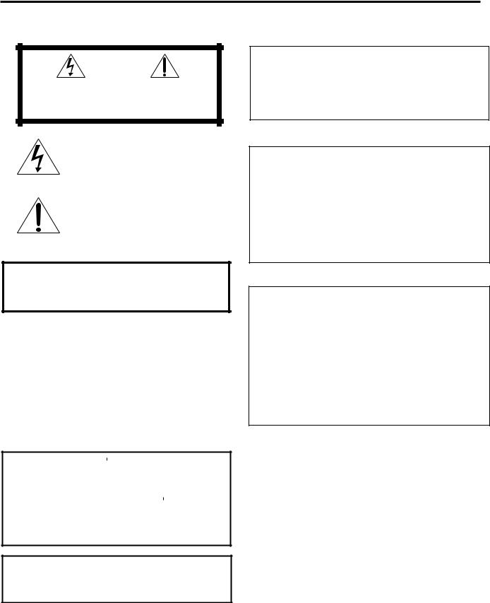
The lightning flash with arrowhead symbol, within an equilateral triangle is intended to alert the user to the presence of uninsulated "dangerous voltage" within the product's enclosure that may be of sufficient magnitude to constitute a risk of electric shock to persons.
The exclamation point within an equilateral triangle is intended to alert the user to the presence of important operating and maintenance (servicing) instructions in the literature accompanying the appliance.
WARNING: TO REDUCE THE RISK OF FIRE OR ELECTRIC SHOCK, DO NOT EXPOSE THIS APPLIANCE TO RAIN OR MOISTURE.
CAUTION
To reduce the risk of electrical shocks, fire, etc.:
1.Do not remove screws, covers or cabinet.
2.Do not expose this appliance to rain or moisture.
ATTENTION
Afin d’éviter tout risque d’électrocution, d’incendie, etc.:
1.Ne pas enlever les vis ni les panneaux et ne pas ouvrir le coffret de l’appareil.
2.Ne pas exposer l’appareil à la pluie ni à l’humidité.
Caution –– STANDBY/ON  button!
Disconnect the mains plug to shut the power off completely. The STANDBY/ON  button in any position does not disconnect the mains line. The power can be remote controlled.
Attention –– Commutateur STANDBY/ON  !
!
Déconnecter la fiche de secteur pour couper complètement le courant. Le commutateur STANDBY/ON  ne coupe jamais complètement la ligne de secteur, quelle que soit sa position. Le courant peut être télécommandé.
Caution –– SPEAKER LOAD SELECTOR switch!
Match the position of SPEAKER LOAD SELECTOR switch on the back panel to the impedance of the speaker connected, to protect from overheating.
Note to CATV system installer:
This reminder is provided to call the CATV system installer’s attention to Section 820-40 of the NEC which provides guidelines for proper grounding and, in particular, specifies that the cable ground shall be connected to the grounding system of the building, as close to the point of cable entry as practical.
Declaration of Conformity
Model Number: |
RX-8020VBK |
Trade Name: |
JVC |
Responsible Party: |
JVC Americas Corp. |
Address: |
1700 Valley Road, Wayne |
Telephone Number: |
New Jersey 07470 |
973-315-5000 |
This device complies with Part 15 of FCC Rules. Operation is subject to the following two conditions: (1) This device may not cause harmful interference, and (2) this device must accept any interference received, including interference that may cause undesired operation.
Déclaration de conformité
Numéro de modèle: |
RX-8020VBK |
Nom de marque: |
JVC |
Personne responsable: US JVC CORP. |
|
Adresse: |
1700 Valley Road |
|
Wayne, N.J. 07470 |
Numéro de téléphone: |
(973) 315-5000 |
Cet ensemble se conforme à la partie 15 des règles de la FCC (Federal Communications Commission), Le fonctionnement est sujet aux deux conditions suivantes:
(1) Cet appareil ne peut pas causer d’interférences nuisibles, et (2) cet appareil doit accepter toute interférence reçue, comprenant des interférences qui peuvent causer un mauvais fonctionnement.
G-1
For Canada/pour Le Canada
THIS DIGITAL APPARATUS DOES NOT EXCEED THE CLASS
B LIMITS FOR RADIO NOISE EMISSIONS FROM DIGITAL APPARATUS AS SET OUT IN THE INTERFERENCE-CAUSING
EQUIPMENT STANDARD ENTITLED “DIGITAL APPARATUS,”
ICES-003 OF THE DEPARTMENT OF COMMUNICATIONS. CET APPAREIL NUMERIQUE RESPECTE LES LIMITES DE
BRUITS RADIOELECTRIQUES APPLICABLES AUX APPAREILS
NUMERIQUES DE CLASSE B PRESCRITES DANS LA NORME SUR LE MATERIEL BROUILLEUR; “APPAREILS
NUMERIQUES”, NMB-003 EDICTEE PAR LE MINISTRE DES
COMMUNICATIONS.
For Canada/pour le Canada
CAUTION: TO PREVENT ELECTRIC SHOCK, MATCH WIDE BLADE OF PLUG TO WIDE SLOT, FULLY INSERT
ATTENTION: POUR EVITER LES CHOCS ELECTRIQUES, INTRODUIRE LA LAME LA PLUS LARGE DE LA FICHE DANS LA BORNE CORRESPONDANTE DE LA PRISE ET POUSSER JUSQUAU FOND
This equipment has been tested and found to comply with the limits for a Class B digital device, pursuant to part 15 of the FCC Rules. These limits are designed to provide reasonable protection against harmful interference in a residential installation.
This equipment generates, uses and can radiate radio frequency energy and, if not installed and used in accordance with the instructions, may cause harmful interference to radio communications. However, there is no guarantee that interference will not occur in a particular installation. If this equipment does cause harmful interference to radio or television reception, which can be determined by turning the equipment off and on, the user is encouraged to try to correct the interference by one or more of the following measures:
Reorient or relocate the receiving antenna.
Increase the separation between the equipment and receiver. Connect the equipment into an outlet on a circuit different from that to which the receiver is connected.
Consult the dealer or an experienced radio/TV technician for help.
Changes or modifications not expressly approved by the manufacturer for compliance could void the user’s authority to operate the equipment.
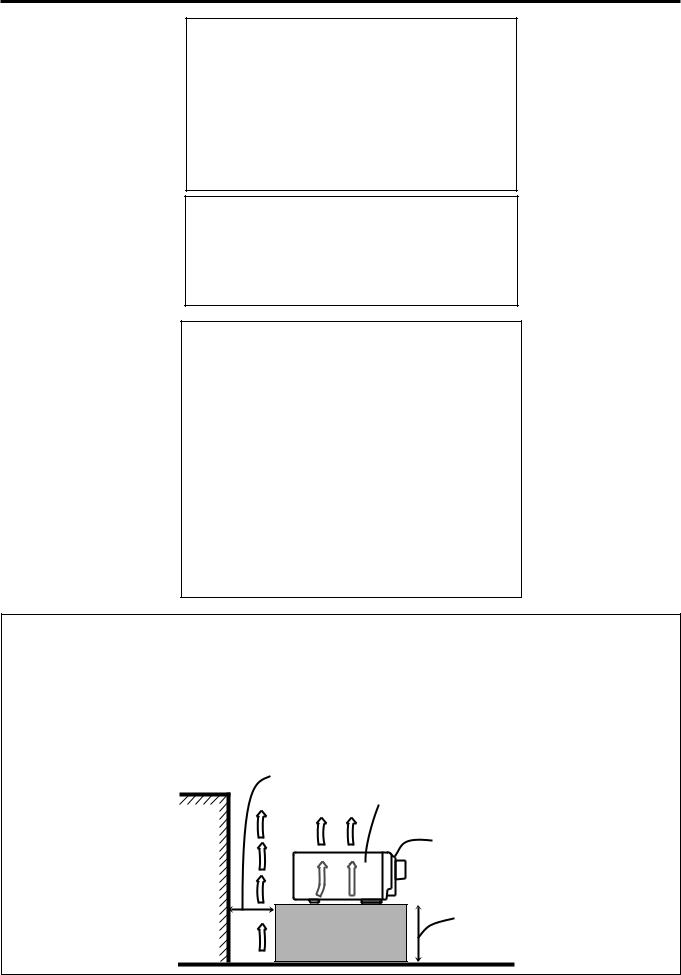
Caution: Proper Ventilation
To avoid risk of electric shock and fire and to protect from damage. Locate the apparatus as follows:
Front: |
No obstructions open spacing. |
Sides: |
No obstructions in 10 cm from the sides. |
Top: |
No obstructions in 10 cm from the top. |
Back: |
No obstructions in 15 cm from the back |
Bottom: |
No obstructions, place on the level surface. |
In addition, maintain the best possible air circulation as illustrated.
Attention: Ventilation Correcte
Pour éviter les chocs électriques, l’incendie et tout autre dégât. Disposer l’appareil en tenant compte des impératifs suivants
Avant: |
Rien ne doit gêner le dégagement |
Flancs: |
Laisser 10 cm de dégagement latéral |
Dessus: |
Laisser 10 cm de dégagement supérieur |
Arrière: |
Laisser 15 cm de dégagement arrière |
Dessous: |
Rien ne doit obstruer par dessous; poser l’appareil |
|
sur une surface plate. |
Veiller également à ce que l’air circule le mieux possible comme illustré.
Spacing 15 cm or more Dégagement de 15 cm
ou plus
RX-8020VBK
Wall or obstructions Mur, ou obstruction
Front
Avant
Stand height 15 cm or more
Hauteur du socle: 15 cm ou plus
Floor
Plancher
G-2

|
Table of Contents |
|
Introduction ................................................ |
2 |
|
Features ...................................................................................... |
2 |
|
Precautions ................................................................................. |
2 |
|
Parts Identification ...................................... |
3 |
|
Getting Started ........................................... |
5 |
|
Before Installation ...................................................................... |
5 |
|
Checking the Supplied Accessories ........................................... |
5 |
|
Connecting the FM and AM Antennas ....................................... |
5 |
|
Connecting the Speakers ............................................................ |
6 |
|
Connecting Audio/Video Components ....................................... |
8 |
|
7Analog Connections ............................................................... |
8 |
|
7 Digital Connections .............................................................. |
13 |
|
7 USB Connection ................................................................... |
14 |
|
Connecting the Power Cord ..................................................... |
15 |
|
Putting Batteries in the Remote Control .................................. |
15 |
|
Basic Operations ....................................... |
16 |
|
Turning On the Power .............................................................. |
16 |
|
Selecting the Source to Play ..................................................... |
16 |
|
Adjusting the Volume ............................................................... |
18 |
|
Selecting the Front Speakers .................................................... |
18 |
|
Listening Only with Headphones ............................................. |
18 |
|
Selecting the Analog or Digital Input Mode ............................ |
19 |
|
Muting the Sound ..................................................................... |
20 |
|
Changing the Display Brightness ............................................. |
20 |
|
Using the Sleep Timer .............................................................. |
20 |
|
Basic Settings ........................................... |
21 |
|
Basic Procedure ........................................................................ |
21 |
|
1 |
Setting the Speakers ........................................................... |
22 |
2 |
Selecting Channel Numbers to Reproduce |
|
|
Multi-channel Digital Software ................................... |
23 |
3 |
Setting the Speaker Distance ............................................. |
23 |
4 |
Setting the Bass Sounds ..................................................... |
24 |
5 |
Setting the Dynamic Range ............................................... |
24 |
6 |
Setting the Digital Input (DIGITAL IN) Terminals ........... |
25 |
7 |
Setting the Component Video Input ................................... |
25 |
8 |
Memorizing the Volume Level for Each Source ................ |
26 |
9 |
Showing the Text Information on the Display ................... |
26 |
Receiving Radio Broadcasts ........................ |
27 |
|
Tuning into Stations Manually ................................................. |
27 |
|
Using Preset Tuning ................................................................. |
27 |
|
Selecting the FM Reception Mode ........................................... |
28 |
|
Operating the Tuner Using the On-Screen Display .................. |
29 |
|
Setting Sound ........................................... |
30 |
Attenuating the Input Signal .................................................... |
30 |
Turning Analog Direct On and Off .......................................... |
30 |
Reinforcing the Bass ................................................................ |
31 |
Activating the Subwoofer Sound ............................................. |
31 |
Using Surround Modes and DSP Modes ........ |
32 |
7 Surround Modes ................................................................... |
32 |
Reproducing Theater Ambience ................................................ |
32 |
Introducing the Surround Modes ............................................. |
32 |
7 DSP Modes ........................................................................... |
34 |
Available Surround and DSP Modes According to |
|
the Speaker Layouts ........................................................... |
35 |
Activating the Surround Modes ............................................... |
36 |
Activating the DSP Modes ....................................................... |
36 |
Using the DVD MULTI Playback Mode .......... |
37 |
Activating the DVD MULTI Playback Mode .......................... |
37 |
Adjusting Sound ........................................ |
38 |
Basic Procedure ........................................................................ |
38 |
Adjusting the Equalization Patterns—DIGITAL EQ ............... |
39 |
Adjusting the Speaker Output Levels—LEVEL ADJUST ...... |
40 |
Adjusting the Sound Parameters for the Surround and |
|
DSP Modes—EFFECT ADJUST ...................................... |
42 |
COMPU LINK Remote Control System ......... |
43 |
TEXT COMPU LINK Remote Control System .. |
44 |
7 Showing the Disc Information on the TV Screen................. |
45 |
7 Searching for a Disc (Only for the CD player) .................... |
46 |
7 Entering the Disc Information .............................................. |
47 |
AV COMPU LINK Remote Control System .... |
49 |
Operating JVC’s Audio/Video Components ... |
51 |
Operating Audio Components .................................................. |
51 |
Operating Video Components .................................................. |
53 |
Operating Other Manufacturers’ Video |
|
Equipment ............................................ |
54 |
Troubleshooting ......................................... |
57 |
Specifications............................................ |
59 |
1


 Introduction
We would like to thank you for purchasing one of our JVC products.
Before operating this unit, read this manual carefully and thoroughly to obtain the best possible performance from your unit, and retain this manual for future reference.
Features |
|
Precautions |
Dolby Digital EX* |
|
Power sources |
Dolby Digital EX is newly introduced surround encoding format as an extension of multi-channel Dolby Digital, designed to add an extra surround channel to Dolby Digital 5.1-channel. By using a matrix encoding/decoding method, additional “surround back” channel signal is encoded (and decoded) in both the left and right surround channel signals.
DTS-ES Extended Surround (DTS-ES)**
DTS-ES is another new format developed by Digital Theater Systems, Inc., adding a surround back channel on the basis of DTS Digital Surround.
Dolby Pro Logic II*
Dolby Pro Logic II converts all 2-channel stereo software, especially Dolby Surround encoded software, into 5-channel (plus subwoofer) signals. It reproduces realistic Surround sounds approaching to Dolby Digital 5.1-channel. Dolby Pro Logic II has two modes to reproduce—Movie mode and Music mode.
Neo:6**
Neo:6 can reproduce realistic Surround fields by converting 2-channel stereo software into 6-channel (plus subwoofer) signals. Neo:6 has two modes to reproduce—Neo:6 Cinema and Neo:6 Music.
DAP (Digital Acoustic Processor)
Sound field simulation technology allows precise ambience recreation of existing theaters and halls. Thanks to the highperformance DSP (Digital Signal Processor) and high-capacity memory, you can enjoy 5.1-channel surround by playing 2-channel or multi-channel software.
Multi-channel headphone virtual surround sound—3D HEADPHONE
•When unplugging the receiver from the wall outlet, always pull the plug, not the AC power cord.
•Do not handle the AC power cord with wet hands.
•If you are not going to operate the receiver for an extended period of time, unplug the AC power cord from the wall outlet.
Ventilation
High power amplifiers built in this receiver will generate heat inside the cabinet. For safety, observe the following carefully.
•Make sure there is good ventilation around the receiver. Poor ventilation could overheat and damage the receiver.
•Do not block the ventilation openings or holes. (If the ventilation openings or holes are blocked by a newspaper or cloth, etc., the heat may not be able to get out.)
Others
•Should any metallic object or liquid fall onto the unit, unplug the unit and consult your dealer before operating any further.
•Do not expose this apparatus to rain, moisture, dripping or splashing and that no objects filled with liquids, such as vases shall be placed on the apparatus.
•Do not disassemble the unit since there are no user serviceable parts inside.
If anything goes wrong, unplug the AC power cord and consult your JVC dealer.
The built-in headphone virtual surround system is compatible with Multi-channel software like Dolby Digital, DTS Surround, etc. Thanks to the new signal processing algorithms used by the highperformance DSP, you can enjoy a natural surround sound through the headphones.
COMPU LINK/TEXT COMPU LINK/AV COMPU LINK remote control systems
These COMPU LINK remote control systems allow you to operate other JVC’s audio/video components from this receiver.
*Manufactured under license from Dolby Laboratories. “Dolby,” “Pro Logic,” and the double-D symbol are trademarks of Dolby
Laboratories.
**“DTS,” “DTS-ES Extended Surround” and “Neo:6” are trademarks of Digital Theater Systems, Inc.
2

 Parts Identification
Become familiar with the buttons and controls on the receiver before use.
Refer to the pages in parentheses for details.
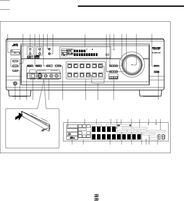
Front Panel
1 |
2 3 4 5 67 8 |
|
|
|
|
9 |
|
pqw e r t |
y |
||||||
|
|
|
|
|
|
|
RX-8020V AUDIO/VIDEO CONTROL RECEIVER |
|
|
||||||
|
FM/AM TUNING |
FM/AM PRESET |
|
FM MODE |
|
|
|
|
|
|
|
|
|
|
|
|
|
|
|
|
ANALOG |
L |
C |
R |
DGTL AUTO |
DVD MULTI |
PRO LOGIC |
TUNED STEREO |
|
|
|
|
STANDBY |
|
|
|
LINEAR PCM |
SUBWFR |
LFE |
|
|
DSP 3D - PHONIC MIDNIGHT MODE |
MASTER VOLUME |
|
|||
|
|
|
|
MEMORY |
|
|
|
|
|
|
|||||
|
|
|
|
|
|
HEADPHONE |
DIGITAL EQ INPUT ATT ONETOUCH OPERATION |
|
|
||||||
|
|
|
|
|
LS |
S |
RS |
|
|
|
|
||||
|
|
|
|
|
DIGITAL |
|
|
|
|
AUTO MUTING |
|
|
|||
|
|
|
|
|
|
SB |
|
|
|
|
|
|
|
||
|
STANDBY/ON |
|
|
|
|
|
|
|
|
|
|
|
|
|
|
|
|
|
|
|
|
SPEAKERS 1 2 |
|
|
|
|
SLEEP VOLUME |
|
|
||
|
SPEAKERS ON/OFF |
|
|
|
|
|
|
|
|
|
|
|
|
|
|
|
1 |
|
|
|
|
|
|
|
|
|
|
|
|
|
|
|
|
|
SURROUND/DSP |
INPUT |
DVD MULTI |
DVD |
VCR 1 |
VCR 2 |
VIDEO |
TV SOUND/DBS |
LEVEL |
|
|||
|
|
|
|
|
|
|
|
|
|
DIGITAL |
|
||||
|
SURROUND |
DSP |
|
OFF |
ANALOG/DIGITAL |
|
|
|
|
|
|
|
EQ |
ADJUST |
ANALOG DIRECT |
|
2 |
|
|
|
|
|
|
|
|
|
|
|
|
|
|
|
|
|
|
|
INPUT ATT |
|
|
|
|
|
|
|
|
|
|
|
SUBWOOFER OUT ON/OFF |
|
|
|
|
|
|
|
|
|
|
|
SOURCE NAME |
|
|
|
USB AUDIO |
|
VIDEO |
|
|
|
|
|
|
|
|
EFFECT |
SETTING |
BASS BOOST |
|
|
|
|
|
|
|
|
|
|
|
|
|
|
|||
|
|
S-VIDEO |
VIDEO |
L—AUDIO—R |
PHONO |
CD |
CDR |
TAPE / MD |
USB AUDIO |
FM / AM |
|
|
|||
|
|
|
|
|
|
|
|
||||||||
|
|
|
|
|
|
|
|
|
|
|
|
|
CONTROL |
|
|
|
|
|
|
|
|
|
|
|
|
|
|
|
DOWN |
UP |
|
SOURCE NAME
PHONES
u i o ; |
a s |
d f |
g |
h |
USB A UDIO
Display Window
PUSH |
OPEN |
|
S- VIDEO
VIDEOVIDEO
1 |
2 |
3 |
4 5 6 |
7 |
8 |
9 |
0 - |
L—AUDIO—
R
When using the VIDEO input terminals and/or USB AUDIO terminal on the front panel, detach the terminal cover.
ANALOG |
L |
C |
R |
DGTL AUTO |
DVD MULTI |
PRO LOGIC |
TUNED STEREO |
|
|
DSP 3D - PHONIC MIDNIGHT MODE |
|||||
LINEAR PCM |
SUBWFR |
LFE |
|
|
|||
|
|
HEADPHONE DIGITAL EQ |
INPUT ATT ONETOUCH OPERATION |
||||
|
LS |
S |
RS |
|
|
||
DIGITAL |
|
|
|
AUTO MUTING |
|||
|
|
|
|
|
|
||
|
|
SB |
|
|
|
|
|
|
SPEAKERS 1 2 |
|
|
|
SLEEP VOLUME |
||
= ~ ! @ # $ %^ &
Front Panel
1 STANBY/ON  button and STANDBY lamp (16)
2• SPEAKERS ON/OFF 1 button (18)
•SPEAKERS ON/OFF 2 button (18) 3 FM/AM TUNING 5 / ∞ buttons (27) 4 DSP button and lamp (36)
5 FM/AM PRESET 5 / ∞ buttons (27, 28)
6 SURROUND/DSP OFF button (36)
7 FM MODE button (28)
8 MEMORY button (27)
9 Display window (16) p EFFECT button (42)
q DIGITAL EQ (equalization) button (39) w Remote sensor (15)
e LEVEL ADJUST button (41) r SETTING button (21)
t MASTER VOLUME control (18)
y ANALOG DIRECT button and lamp (30) u PHONES jack (18)
i SUBWOOFER OUT ON/OFF button (31) o SURROUND button and lamp (36)
; USB AUDIO terminal (14) a VIDEO input jacks (10)
s • INPUT ANALOG/DIGITAL button (19)
• INPUT ATT button (30)
dSource selecting buttons and lamps (16, 17, 19, 27, 28, 37)
DVD MULTI, DVD, VCR 1, VCR 2, VIDEO, TV SOUND/DBS, PHONO, CD, CDR, TAPE/MD, USB AUDIO, FM/AM
f SOURCE NAME buttons (17)
g CONTROL UP 5/DOWN ∞ buttons (21, 41, 42) h BASS BOOST button and lamp (31)
Display Window
1 |
ANALOG indicator (19) |
2 |
Speaker indicators and signal indicators (17) |
3 |
DGTL (digital) AUTO indicator (19) |
4 |
DVD MULTI indicator (37) |
5 |
DSP indicator (18, 34) |
6 |
• PRO LOGIC indicator (33) |
|
• PRO LOGIC II indicator (32) |
7 |
3D-PHONIC indicator (33, 34) |
8 |
MIDNIGHT MODE indicator (24) |
9 |
TUNED indicator (27) |
0 |
STEREO indicator (27, 28) |
- ONE TOUCH OPERATION indicator (26) = Digital signal format indicators (19)
~ SPEAKERS 1/2 indicators (18) ! Main Display
@ HEADPHONE indicator (18, 34)
# DIGITAL EQ (equalization) indicator (39) $ INPUT ATT (attenuator) indicator (30) % SLEEP indicator (20)
^ AUTO MUTING indicator (28) & VOLUME level indicator (16, 20)
3
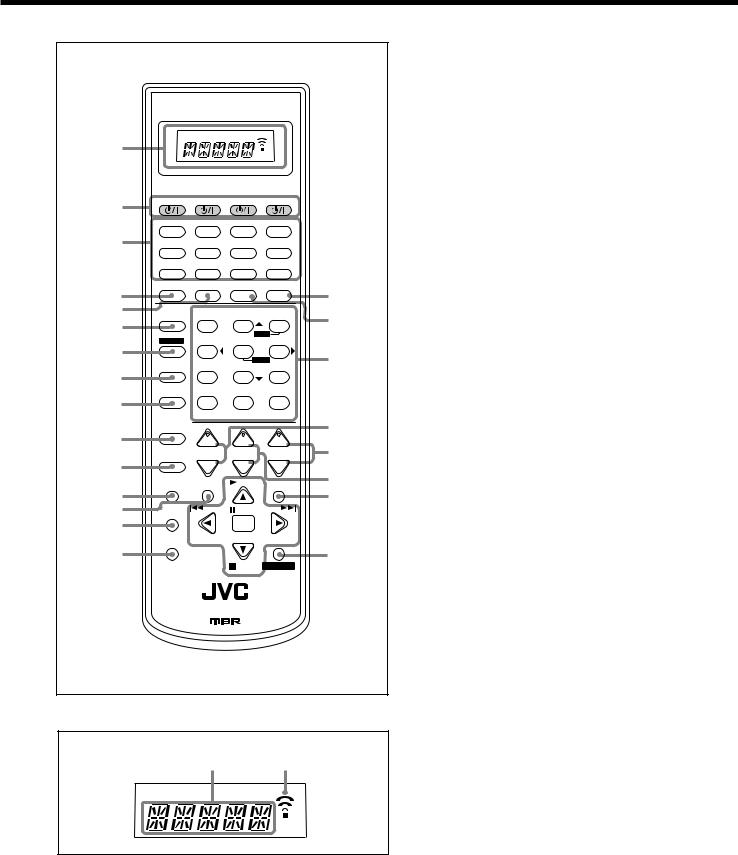
Remote Control
A/V CONTROL RECEIVER
1
2 |
CATV/DBS |
VCR1 |
TV |
AUDIO |
|
|
|
|
|
|
DVD DVD MULTI |
CD |
FM/AM |
|
3 |
TV/DBS |
VIDEO |
CDR |
PHONO |
|
VCR1 |
VCR2 |
TAPE/MD |
USB |
4 |
SURROUND |
DSP |
SURR/DSP ANALOG/DIGITAL |
|
|
|
OFF |
INPUT |
|
5 |
ANALOG |
BASS |
FRONT•L FRONT•R |
|
|
DIRECT |
BOOST |
||
6 |
|
1 |
2 |
3 |
|
|
|
MENU |
|
|
SOUND |
TEST |
CENTER |
SUBWFR |
7 |
|
4 |
5 |
6 |
|
|
|
ENTER |
|
|
DIMMER |
|
SURR•L |
SURR•R |
8 |
|
7/P |
8 |
9 |
|
MUTING DIGITALEQ SBACK•L SBACK•R |
|||
9 |
|
10 |
0 |
+10 |
|
|
RETURN |
FMMODE |
100+ |
|
CATV/DBS |
|
|
|
p |
CONTROL |
+ |
+ |
+ |
|
CH/ LEVEL TV VOL |
VOLUME |
||
q |
TV/VIDEO |
− |
− |
− |
|
TEXT |
MENU |
PLAY |
|
|
DISPLAY |
EXIT |
||
w |
|
|||
|
|
|
|
|
e |
REC |
/REW |
PAUSE |
FF/ |
|
PAUSE |
|
|
|
r |
|
|
SET |
|
|
SLEEP |
DOWN – TUNING – UP |
||
|
|
|
|
|
t |
|
|
|
|
|
|
|
STOP |
CONTROL |
RM-SRX8020J REMOTE CONTROL
Remote Control
1 Display window
2  buttons (16, 53 – 56)
CATV/DBS  , VCR1
  , TV
, TV  , AUDIO
3Source selecting buttons (16, 17, 19, 27, 28, 37)
DVD, DVD MULTI, CD, FM/AM, TV/DBS, VIDEO, CDR, PHONO, VCR1, VCR2, TAPE/MD, USB
4 SURROUND button (36)
5 DSP button (36)
6 ANALOG DIRECT button (30)
7 SOUND button (31, 39, 41)
8 DIMMER button (20)
9 MUTING button (20)
p CATV/DBS CONTROL button (55) q TV/VIDEO button (53)
w TEXT DISPLAY button (45 – 48)
y
e MENU button (21, 29 – 31, 38) r REC PAUSE button (52, 53, 55)
ut SLEEP button (20)
y ANALOG/DIGITAL INPUT button (19)
uSURR (surround)/DSP OFF button (36) i i • 10 keys for operating tuner (28)
•10 keys for adjusting sound (31, 39, 41)
•10 keys for operating audio/video components (51 – 55) o • CH (channel) +/– buttons (53 – 55)
o |
• LEVEL +/– buttons* (39, 41) |
|
These buttons function only after pressing 10 keys which are marked with |
||
|
||
; |
an asterisk (*). |
|
|
; VOLUME +/– buttons (18) |
aa TV VOL (volume) +/– buttons (53, 54)
ss EXIT button (21, 30, 31, 38, 40, 42, 45 – 47) d • TUNING UP /DOWN buttons (27)
|
d |
• |
On-screen operating buttons (21, 29 – 31, 38 – 40, 42, 45 – 48) |
|
|||
|
|
• |
Operating buttons for audio/video components (51 – 53, 55, 56) |
ff CONTROL button (51 – 53)
Remote control display window
1 2
Remote control display window
1Remote control operation mode display (16)
•Remote control operation mode such as “DVD,” “CD,” “SOUND,” etc. appears.
When the remote control operation mode changes, it is shown on the display.
2Signal transmission indicator
• Lights up when transmitting the remote control signals.
4

 Getting Started
This section explains how to connect audio/video components and speakers to the receiver, and how to connect the power supply.
Before Installation
General Precautions
•Be sure your hands are dry.
•Turn the power off to all components.
•Read the manuals supplied with the components you are going to connect.
Locations
•Install the receiver in a location that is level and protected from moisture.
•The temperature around the receiver must be between –5˚C and 35˚C (23˚F and 95˚F ).
•Make sure there is good ventilation around the receiver. Poor ventilation could cause overheating and damage the receiver.
Handling the receiver
•Do not insert any metal object into the receiver.
•Do not disassemble the receiver or remove screws, covers, or cabinet.
•Do not expose the receiver to rain or moisture.
Checking the Supplied Accessories
Check to be sure you have all of the following items, which are supplied with the receiver.
The number in the parentheses indicates quantity of the pieces supplied.
•Remote Control (1)
•Batteries (2)
•AM Loop Antenna (1)
•FM Antenna (1)
If anything is missing, contact your dealer immediately.
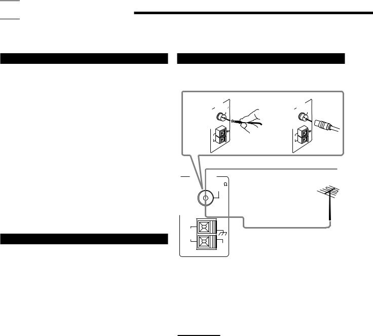
Connecting the FM and AM Antennas
FM Antenna Connections
A |
|
ANTENNA |
75 |
B |
|
ANTENNA |
75 |
|
|
FMAXIAL |
|
|
FMAXIAL |
||
|
|
|
CO |
|
|
|
CO |
AM |
|
AM |
AM |
|
AM |
||
LO |
OP |
|
EXT |
LO |
OP |
|
EXT |
|
|
|
|
|
|
||
FM Antenna (supplied)
Extend the supplied FM antenna horizontally.
AM |
Outdoor FM Antenna Cable (not |
LOOP |
supplied)
AM
EXT
A.Using the Supplied FM Antenna
The FM antenna provided can be connected to the FM 75 Ω COAXIAL terminal as temporary measure.
B.Using the Standard Type Connector (Not Supplied)
A standard type connector should be connected to the FM 75 Ω COAXIAL terminal.
Note:
If reception is poor, connect the outdoor FM antenna (not supplied).
Before attaching a 75 Ω coaxial cable (the kind with a round wire going to an outdoor antenna), disconnect the supplied FM antenna.
5
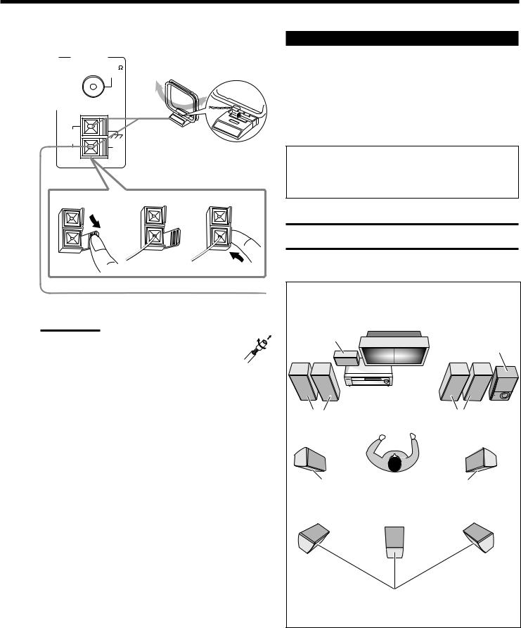
AM Antenna Connections
ANTENNA |
Turn the loop until you have |
FM 75 |
the best reception. |
COAXIAL |
|
AM |
|
AM Loop Antenna |
LOOP |
|
(supplied) |
|
AM |
|
|
|
|
|
EXT |
Snap the tabs on the loop into the |
|
|
|
|
|
slots of the base to assemble the |
|
|
AM loop. |
1 |
2 |
3 |
Connecting the Speakers
You can connect the following speakers:
•Two pairs of front speakers to produce normal stereo sound.
•One pair of surround speakers to enjoy the surround effect.
•One surround back speaker or one pair of surround back speakers to enjoy 6.1-channel sound reproduction.
•One center speaker to produce more effective surround effect (to emphasize human voices).
•One subwoofer to enhance the bass.
IMPORTANT:
After connecting the speakers listed above, set the speaker setting information properly to obtain the best possible Surround and DSP effect. For details, see page 22.
CAUTION:
Use speakers with the SPEAKER IMPEDANCE indicated by the speaker terminals.
Outdoor single vinyl-covered wire (not supplied)
Notes:
• If the AM loop antenna wire is covered with vinyl (not supplied), remove the vinyl by twisting it as shown in the diagram.
•Make sure the antenna conductors do not touch any other terminals, connecting cords and power cord. This could cause poor reception.
•If reception is poor, connect an outdoor single vinyl-covered wire
(not supplied) to the AM EXT terminal. (Keep the AM loop antenna connected.)
Typical speaker layout |
|
Center speaker |
|
|
Subwoofer |
Left front speaker(s) |
Right front speaker(s) |
Left surround speaker |
Right surround speaker |
Surround back speaker(s) |
|
|
6 |
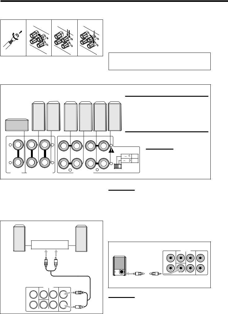
Basic connecting procedure
1 |
2 |
3 |
4 |
1Cut, twist and remove the insulation at the end of each speaker signal cable (not supplied).
2Turn the knob counterclockwise.
3Insert the speaker signal cable.
4Turn the knob clockwise.
For each speaker (except for a subwoofer), connect the (+) and (–) terminals on the rear panel to the (+) and (–) terminals marked on the speakers.
Connecting the front, center and surround speakers
Surround |
|
|
speakers |
Front speakers 2Front speakers 1 |
|
Right / Left |
Right / Left |
Right / Left |
Center speaker
IMPORTANT:
To obtain the best possible output power from the receiver, and to prevent the receiver from being overheated, the receiver has the SPEAKER LOAD SELECTOR which has to be set as follows:
•Set it to “HIGH” when the impedance of the front speakers connected is within the range of 8 Ω to 16 Ω.
•Set it to “LOW” when the impedance of the front speakers connected is within the range of 4 Ω to 6 Ω.
CAUTION : SPEAKER IMPEDANCE 8 16
16
+ |
|
+ |
|
|
|
|
+ |
|
|
|
|
|
|
|
|
|
CAUTION : |
|
|
|
|
|
|
|
|
|
SPEAKER IMPEDANCE |
||
|
|
|
RIGHT |
LEFT |
RIGHT |
LEFT |
4 |
6 |
LOW |
|
|
|
|
|
|
|
|||
– |
|
– |
|
|
|
|
8 |
16 |
HIGH |
|
|
|
|
|
– |
|
|
||
CENTER |
RIGHT |
LEFT |
2 |
|
1 |
|
SPEAKER LOAD SELECTOR |
||
SURROUND |
SPEAKERS |
|
|
||||||
|
FRONT SPEAKERS |
|
|
|
|
||||
SPEAKER |
|
|
|
|
|
||||
|
|
|
|
|
|
|
|
|
|
Note:
You can connect two pairs of front speakers (one pair to the FRONT
SPEAKERS 1 terminals, and another pair to the FRONT SPEAKERS 2 terminals).
Connecting the surround back speakers
To fully enjoy Dolby Digital EX and DTS-ES Extended Surround (see pages 32 and 33), you need to connect the surround back speakers through a power amplifier connected to the PRE OUT SURR BACK jacks on the rear panel, using a cable with RCA pin plugs (not supplied). Connect the white plug to the audio left jack, and the red plug to the audio right jack.
|
Power amplifier |
Left surround |
Right surround |
back speaker |
back speaker |
PRE OUT
FRONT CENTER SURR SURR BACK
L 


 L
L
R 


 R
R
SUBWOOFER
Note:
If you have selected “1SPK” for the surround back speaker quantity (see page 22), connect the surround back speaker to the PRE OUT
SURR BACK L (left) jack.
Connecting the subwoofer speaker
You can enhance the bass by connecting a subwoofer.
Connect the input jack of a powered subwoofer to the PRE OUT SUBWOOFER jack on the rear panel, using a cable with RCA pin plugs (not supplied).
|
PRE OUT |
|
|
FRONT |
CENTER |
SURR |
SURR BACK |
L |
|
|
L |
|
|
|
R |
|
SUBWOOFER |
|
|
Powered |
|
|
|
subwoofer |
|
|
|
Note: |
|
|
|
You can place a subwoofer wherever you like since bass sound is non-directional. Normally place it in front of you.
7
Enhancing your audio system
You can use this receiver as the pre-amplifier (control amplifier) when you connect power amplifiers to the PRE OUT jacks on the rear panel using cables with RCA pin plugs (not supplied). Connect the white plug to the audio left jack, and the red plug to the audio right jack.
|
|
|
Left front |
Right front |
|
|
|
|
|
|
speaker |
speaker |
|
|
|
|
|
|
|
|
|
||
|
|
|
|
|
|
|
|
|
|
|
|
|
|
|
|
Power amplifier |
Center speaker |
||||||||
|
|
|
|
|
|
|
|
|
|
|
|
|
|
|
|
|
|
|
|
|
|
|
|
|
|
|
|
|
|
|
|
|
|
|
|
|
|
|
|
|
|
|
|
|
|
|
|
|
|
|
|
|
|
|
|
|
|
|
|
|
|
|
|
|
|
|
|
|
|
Power amplifier
PRE OUT
FRONT CENTER SURR SURR BACK
L 


 L
L
R 


 R
R
SUBWOOFER
Power amplifier
Power amplifier
Left surround |
Right surround |
speaker |
speaker |
Left |
/ Right |
Surround back speakers
Note:
If you have selected “1SPK” for the surround back speaker quantity (see page 22), connect the surround back speaker to the SURR BACK L (left) jack.
Connecting Audio/Video Components
You can connect the following audio/video components to this receiver. Refer also to the manuals supplied with your components.
Audio Components |
Video Components |
• Turntable |
• VCRs (VCR 1 and VCR 2) |
• CD player* |
• Video camera |
|
|
• Cassette deck or |
• TV* |
MD recorder* |
• DBS tuner* |
• CD recorder* |
• DVD player* |
•Personal computer (PC)
*You can connect these components using the methods described in
“Analog Connections” (see below and page 14) and in “Digital Connections” (see page 13).

 Analog Connections
Audio component connections
Use the cables with RCA pin plugs (not supplied).
Connect the white plug to the audio left jack, and the red plug to the audio right jack.
CAUTION:
If you connect a sound-enhancing device such as a graphic equalizer between the source components and this receiver, the sound output through this receiver may be distorted.
Turntable
Turntable
To audio output
If a ground cable is provided for your turntable, connect the cable to the screw marked (H) on the rear panel.
SUB |
CENTER RIGHT |
LEFT |
AUDIO |
WOOFER |
|
|
|
DVD
SURR (REAR)
PHONO
CD
OUT (REC)
TAPE
MD
IN (PLAY)
OUT (REC)
CDR
IN (PLAY)
Note:
This connection is for the turntable with an MM (moving-magnet) type cartridge.
Any turntables incorporating a small-output cartridge such as an MC (moving-coil) type must be connected to this receiver through a commercial head amplifier or step-up transformer. Direct connection may result in insufficient volume.
8
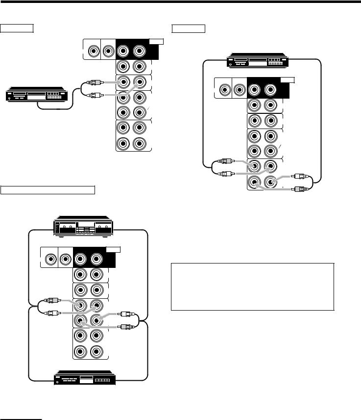
CD player |
|
|
CD recorder |
|
|
|
SUB |
CENTER RIGHT |
LEFT AUDIO |
|
|
|
|
WOOFER |
|
|
|
CD recorder |
|
|
DVD |
|
|
To audio input |
To audio output |
||
|
SURR |
|
|
|||
|
|
|
|
|||
|
|
(REAR) |
|
|
|
|
|
|
PHONO |
|
|
|
|
CD player |
|
CD |
SUB |
CENTER RIGHT |
LEFT |
AUDIO |
|
WOOFER |
|
|
|
||
|
|
|
DVD |
|
|
SURR |
|
|
OUT |
|
|
|
|
|
|
|
|
|
(REAR) |
|
|
|
(REC) |
|
|
|
|
|
|
TAPE |
|
|
|
PHONO |
|
|
MD |
|
|
|
|
|
|
|
|
|
|
|
To audio output |
|
IN |
|
|
|
|
|
(PLAY) |
|
|
|
|
|
|
|
OUT |
|
|
|
CD |
|
|
|
|
|
|
|
|
|
(REC) |
|
|
|
|
|
|
CDR |
|
|
|
OUT |
|
|
|
|
|
(REC) |
|
|
|
|
|
|
|
|
|
|
IN |
|
|
|
TAPE |
|
|
(PLAY) |
|
|
|
MD |
|
|
|
|
|
|
|
IN (PLAY)
OUT (REC)
Cassette deck or MD recorder
Cassette deck
To audio input |
To audio output |
SUB |
CENTER RIGHT |
LEFT |
AUDIO |
WOOFER |
|
|
|
DVD
SURR (REAR)
PHONO
CD
OUT (REC)
TAPE
MD
IN (PLAY)
OUT (REC)
CDR
IN (PLAY)
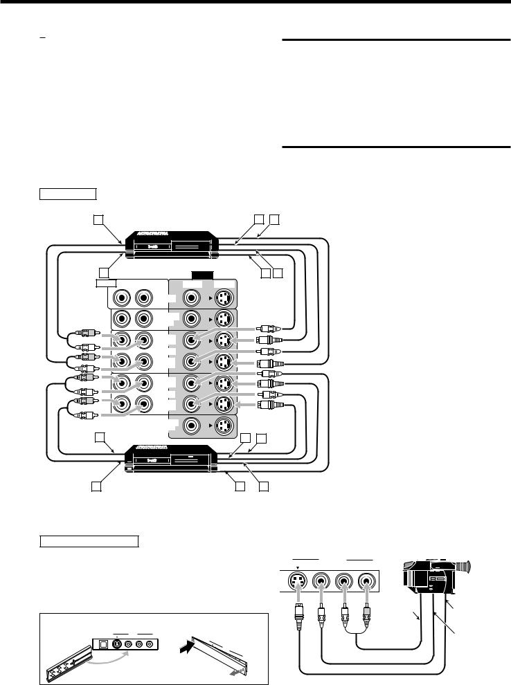
If your audio components have a COMPU LINK or TEXT COMPU LINK jack
•See also page 43 for detailed information about the connection and the COMPU LINK remote control system.
•See also page 44 for detailed information about the connection and the TEXT COMPU LINK remote control system.
To audio input  To audio output MD recorder
Note:
You can connect either a cassette deck or an MD recorder to the TAPE/MD jacks. When connecting an MD recorder to the TAPE/MD jacks, change the source name to “MD,” which will be shown on the display when it is selected as the source. See page 17 for details.
9
Video component connections
Use the cables with RCA pin plugs (not supplied).
Connect the white plug to the audio left jack, the red plug to the audio right jack, and the yellow plug to the video jack.
•If your video components have S-video (Y/C-separation) and/or component video (Y, PB/CB, PR/CR) terminals, connect them using an S-video cable (not supplied) and/or component video cable (not supplied). By using these jacks, you can get a better picture quality in the order—Component video > S-video > Composite video.
VCR(s)
A |
|
S-VHS/VHS VCR |
C |
D |
||
|
|
|
|
|||
|
|
|
|
|
|
|
|
|
|
|
|
|
|
|
|
|
|
|
|
|
|
|
|
|
|
|
|
|
|
|
|
|
|
|
|
|
|
|
|
|
|
IMPORTANT:
This receiver is equipped with the following video jacks—composite video, S-video and component video jacks. You can use any of the three to connect a video component.
However, the video signals from one type of these input jacks are output only through the video output jacks of the same type.
Therefore, if a recording video component and a playing video component are connected to the receiver through the video jacks of the different type, you cannot record the picture. In addition, if the TV and a playing video component are connected to the receiver through the video jacks of the different type, you cannot view the playback picture on the TV.
B |
|
VIDEO |
E F |
AUDIO RIGHT |
LEFT |
VIDEO |
S-VIDEO |
DVD
FRONT
TV SOUND
DBS
OUT (REC)
VCR1
IN (PLAY)
OUT (REC)
VCR2
IN (PLAY)
Å To left/right audio output
MONITOR |
|
|
ı To left/right audio input |
|
OUT |
|
|
Ç To composite video output |
|
A |
C |
D |
||
Î To S-video output |
||||
|
|
|
S-VHS/VHS VCR |
B |
E |
F |
‰ To composite video input Ï To S-video input
Video camera
The VIDEO input jacks on the front panel are convenient when connecting and disconnecting the equipment frequently.
•When you do not use the jacks on the front panel, attach the supplied front terminal cover to protect them from dust.
VIDEO
|
S-VIDEO |
VIDEO |
L—AUDIO—R |
|
|||
|
|
|
|
|
|
|
|
|
|
|
|
|
|
|
|
|
|
|
|
|
|
|
|
|
|
|
|
|
|
|
|
|
|
|
|
|
|
|
|
|
|
|
|
|
|
|
|
|
To audio |
To S-video |
|
|
|
|
|
|
|
|
|
output |
|
• When attaching the cover |
• When removing the cover |
output |
||||||||
|
||||||||||
USB AUDIO |
VIDEO |
|
U |
SB |
|
|
|
|
|
|
S-VIDEO |
VIDEO |
L—AUDIO—R |
|
|
|
|
|
To composite |
||
|
|
|
|
|
AU |
|
|
|
|
|
|
|
|
|
|
DIO |
|
|
|
|
|
|
|
|
PUSH |
|
S-VIDEO |
|
|
|
||
|
|
|
OPEN |
V |
IDE VID |
L— |
|
video output |
||
|
|
|
|
|
|
|
O |
EO |
|
|
|
|
|
|
|
|
|
|
|
AU |
|
|
|
|
|
|
|
|
|
|
DIO |
|
|
|
|
|
|
|
|
|
|
—R |
|
10
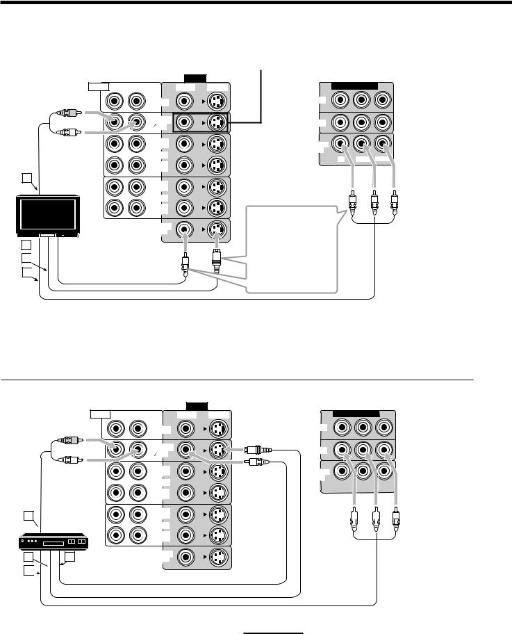
TV and/or DBS tuner |
|
|
|
When connecting the TV to the AUDIO jacks |
|
|
|
|
|
|
(TV SOUND/DBS), DO NOT connect the TV’s video output |
|
|
to these video input jacks. |
|
|
|
|
VIDEO |
|
|
|
AUDIO RIGHT LEFT |
VIDEO |
S-VIDEO |
COMPONENT VIDEO |
|
|
DVD |
|
DVD |
|
|
|
|
|
|
|
FRONT |
|
|
|
|
TV SOUND |
|
DBS |
|
|
DBS |
|
|
|
|
|
|
|
|
|
OUT |
|
MONITOR |
|
|
(REC) |
|
|
|
|
VCR1 |
|
OUT |
|
|
|
Y |
PB/CB PR/CR |
|
|
|
|
||
IN (PLAY)
A
TV
B
C 

D
Å To audio output
ı To composite video input Ç To S-video input
Î To component video input
OUT (REC)
VCR2
IN (PLAY)
MONITOR
OUT
Connect the TV to the appropriate MONITOR
OUT jacks to view a play-backing picture from other connected video components.
|
VIDEO |
|
|
AUDIO RIGHT LEFT |
VIDEO |
S-VIDEO |
COMPONENT VIDEO |
|
DVD |
|
DVD |
|
|
|
|
|
FRONT |
|
|
|
TV SOUND |
|
DBS |
|
DBS |
|
|
|
|
|
A
 DBS tuner
DBS
BD
C

ÅTo audio output ı To S-video output
Ç To component video output Î To composite video output
OUT (REC)
VCR1
IN (PLAY)
OUT (REC)
VCR2
IN (PLAY)
MONITOR
OUT
MONITOR
OUT
|
Y |
|
|
|
|
PB/CB |
|
|
|
|
PR/CR |
|
|
|
|
|
|
|
|
|
|
|
|
|
|
|
|
|
|
|
|
|
|
|
|
|
|
|
|
|
|
|
|
|
|
|
|
|
|
|
|
|
|
|
|
|
|
|
|
|
|
|
|
|
|
|
|
|
|
|
|
|
|
|
|
|
|
|
|
|
|
|
|
|
|
|
|
|
|
|
|
|
|
|
|
|
|
|
|
|
|
|
|
|
|
|
|
|
|
|
|
|
|
|
|
|
|
|
|
|
|
|
|
|
|
|
|
|
|
|
|
|
|
|
|
|
|
|
|
|
|
|
|
|
|
|
|
|
|
|
|
|
|
|
|
Notes:
•When connecting a DBS tuner to the TV SOUND/DBS jacks, change the source name to “DBS,” which will be shown on the display when it is selected as the source. See page 17 for details.
•When connecting a DBS tuner to the component video input jacks, make the component video input setting correctly. See pages 25 and 49 for details.
11

DVD player
• When you connect a DVD player with stereo output jacks:
|
VIDEO |
|
|
AUDIO RIGHT LEFT |
VIDEO |
S-VIDEO |
COMPONENT VIDEO |
|
DVD |
|
DVD |
|
|
|
|
|
FRONT |
|
|
A
DVD player
DVD |
BD
C


TV SOUND |
DBS |
|
|
DBS |
|
||
|
|
||
OUT |
MONITOR |
|
|
(REC) |
|
||
VCR1 |
OUT |
|
|
Y |
PB/CB PR/CR |
||
|
IN (PLAY)
OUT (REC)
VCR2
IN (PLAY)
MONITOR
OUT
Å To front left/right audio output ı To S-video output
Ç To component video output
ÎTo composite video output
•When you connect a DVD player with its analog discrete output (5.1-channel reproduction) jacks:
A |
B |
C |
DVD player |
|
|
|
G |
DVD |
F
D E
|
|
|
|
|
|
VIDEO |
|
SUB |
CENTER RIGHT |
LEFT |
AUDIO |
RIGHT |
LEFT |
VIDEO |
S-VIDEO |
WOOFER |
|
||||||
DVD |
|
|
SURR |
|
|
DVD |
|
|
|
|
(REAR) |
|
|
FRONT |
|
|
|
|
PHONO |
|
|
TV SOUND |
|
|
|
|
|
|
DBS |
|
|
|
|
|
|
|
|
|
|
|
|
|
CD |
|
|
OUT |
|
|
|
|
|
|
(REC) |
|
|
|
|
|
|
|
|
VCR1 |
|
|
|
|
OUT |
|
|
IN |
|
|
|
|
(REC) |
|
|
(PLAY) |
|
|
|
|
TAPE |
|
|
|
|
|
|
|
MD |
|
|
OUT |
|
|
|
|
IN |
|
|
|
|
|
|
|
|
|
(REC) |
|
|
|
|
|
(PLAY) |
|
|
|
|
|
|
|
|
|
|
|
|
|
|
|
|
|
|
VCR2 |
|
|
|
|
OUT |
|
|
IN |
|
|
|
|
(REC) |
|
|
(PLAY) |
|
|
|
|
CDR |
|
|
MONITOR |
|
|
|
|
IN |
|
|
|
|
|
|
|
(PLAY) |
|
|
OUT |
|
Note:
When connecting a DVD player to the component video input jacks, make the component video input setting correctly. See pages 25 and 49 for details.
COMPONENT VIDEO
DVD
DBS
MONITOR
OUT
Y PB/CB PR/CR
Å To rear left/right audio output ı To center audio output
Ç To subwoofer output
Î To front left/right audio output ‰ To composite video output Ï To S-video output
Ì To component video output
12
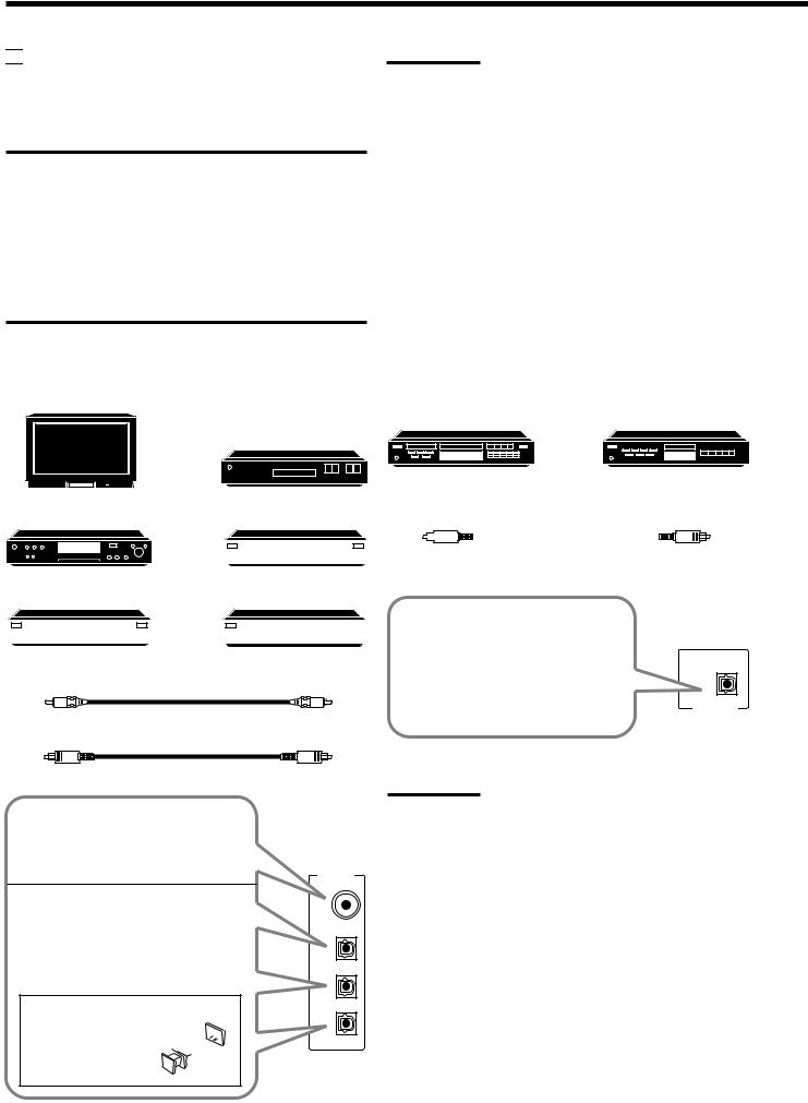

 Digital Connections
This receiver is equipped with four DIGITAL IN terminals—one digital coaxial terminal and three digital optical terminals—and one DIGITAL OUT terminal.
IMPORTANT:
•When connecting a DVD player, digital TV broadcast tuner or DBS tuner using the digital terminals, you also need to connect it to the video jacks on the rear. Without connecting it to the video jacks, you can view no playback picture.
•After connecting the components using the DIGITAL IN terminals, set the following correctly if necessary.
–Set the digital input (DIGITAL IN) terminal setting correctly. For details, see “6 Setting the Digital Input (DIGITAL IN) Terminals” on page 25.
–Select the digital input mode correctly. For details, see “Selecting the Analog or Digital Input Mode” on page 19.
Notes:
•When shipped from the factory, the DIGITAL IN terminals have been set for use with the following components:
–DIGITAL 1 (coaxial): For DVD player
–DIGITAL 2 (optical): For CD player
–DIGITAL 3 (optical): For digital TV broadcast tuner
–DIGITAL 4 (optical): For CD recorder
•When you want to operate the CD player, CD recorder, or MD recorder using the COMPU LINK remote control system, connect the target component also as described in “Analog Connections”
(see page 9).
•When you want to operate a DVD player using the AV COMPU LINK remote control system (see page 49), connect the DVD player also as described in “Analog Connections” (see page 12).
Digital input terminals |
|
Digital output terminal |
You can connect any digital equipment as follows.
Digital TV
CD recorder |
MD recorder |
DBS tuner
 Digital VCR
DBS
DVD player
DVD |
|
|
|
|
|
|
|
|
|
|
|
Digital optical cable (not supplied) |
|
|
CD player |
|
|
|
|
|
|
|
between digital optical terminals |
|||
|
|
|
|
|
|
|
|
|
|
|
|
|
|
|
|
|
|
|
|
|
|
|
|
|
|
|
|
|
|
|
|
|
|
|
|
|
|
|
|
|
CD recorder |
|
|
MD recorder |
||
|
|
|
|
|
|
|
|
|
|
|
|
|
|
|
|
Digital coaxial cable (not supplied) between digital coaxial terminals
Digital optical cable (not supplied) between digital optical terminals
When the component has a digital coaxial output terminal, connect it to the DIGITAL 1 (DVD) terminal, using a digital coaxial cable (not supplied).
When the component has a digital optical output terminal, connect it to the DIGITAL 2 (CD), DIGITAL 3 (TV) or DIGITAL 4 (CDR) terminal, using a digital optical cable (not supplied).
Before connecting a digital optical cable, unplug the 
 protective plug.


DIGITAL IN
DIGITAL 1 (DVD)
DIGITAL 2 (CD)
DIGITAL 3 (TV)
DIGITAL 4 (CDR)
When the digital recording equipment such as an MD recorder and CD recorder has a digital optical input terminal, connecting it to the DIGITAL OUT terminal enables you to perform digital-to- digital recording.
Note:
PCM/DOLBY DIGITAL /DTS
DIGITAL OUT
The digital signal format output through the DIGITAL OUT terminal is the same as that of the input signal. This means that when the DTS
Digital Surround signals are input, the DTS Digital Surround signals are output.
13
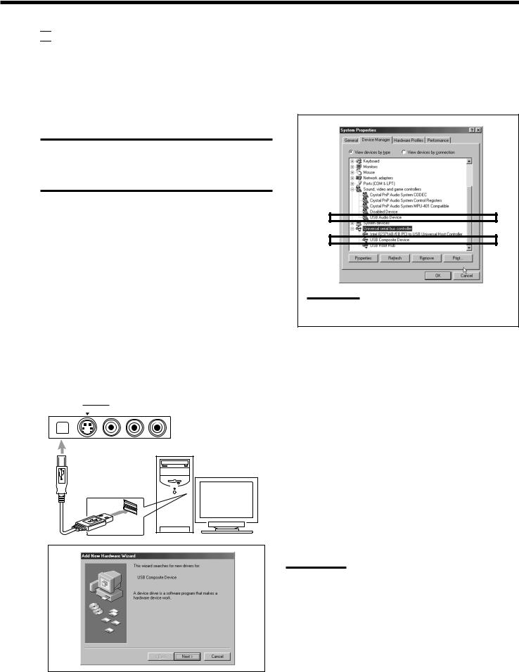

 USB Connection
This receiver is equipped with a USB terminal on the front panel. You can connect your PC to this terminal and enjoy sound reproduced through your PC.
When you connect your PC for the first time, follow the procedure below.
•Remember you cannot send any signal or data to your PC from this receiver.
IMPORTANT
•Check if your PC equipped with the CD-ROM drive is running on WindowsR 98*, WindowsR Me* or WindowsR XP* and prepare its
CD-ROM.
•Check your PC’s BIOS setting—whether USB is available, and whether USB IRQ is set to “AUTO” or to available IRQ number.
How to install the USB drivers
The following procedure is described using the English version of WindowsR 98. If your PC is running on a different version of operation system or language, the screens shown on your PC’s monitor will differ from the ones used in the following procedure.
1.Turn on your PC and start running WindowsR 98, WindowsR Me or WindowsR XP.
If the PC has been turned on, quit all the applications now running.
2.Turn on the receiver, and press USB AUDIO on the front panel or USB on the remote control.
The lamp on the USB AUDIO on the front panel button lights up.
3.Connect the receiver to the PC using a USB cable (not supplied).
Your PC automatically recognizes this connection, and shows
the following screen on the monitor.
USB AUDIO |
VIDEO |
|
|
||||
|
|
||||||
|
|
S-VIDEO |
VIDEO |
L—AUDIO—R |
|||
|
|
|
|
|
|
|
|
|
|
|
|
|
|
|
|
|
|
|
|
|
|
|
|
PC
USB cable
4.Install the USB drivers following the instructions shown on the PC’s monitor.
5.Check if the drivers are correctly installed.
1.Open the Control Panel on your PC: Select [Start] = [Settings] = [Control Panel].
2.Select [System], then [Device Manager] and click [Sound, video and game controllers] and [Universal serial bus controllers].
The following window appears, and you can check whether the drivers are installed.
Note:
The items shown on the PC’s monitor differ depending on your PC settings.
6.Change the PC audio setting.
1.If you have closed Control Panel, open it again: Select [Start] = [Settings] = [Control Panel].
2.Click [Multimedia], then select “USB Audio Device [1]” for “Playback” of “Audio,” and close the window.
To play back a CD from CD-ROM drive on PC, click [Multimedia], [CD Music], then check [Enable digital CD audio for this CD-ROM device].
Now PC is ready for playback through the USB connection.
After installation is completed, you can use your PC as the playback source. The PC automatically recognizes the receiver whenever a USB cable is connected between the PC and the receiver while the receiver is turned on.
•When not using the PC as the playback source, disconnect the USB cable.
To play back sounds on the PC, refer to the manuals supplied with the sound reproduction application installed in the PC.
Notes:
•DO NOT turn off the receiver or disconnect the USB cable while installing the drivers and for several seconds while your PC is recognizing the receiver.
•Use a full speed USB cable (revision 1.0). Recommended cord length is 1.5 m.
•If your PC does not recognize the receiver, disconnect the USB cable and connect it again. If it does not work yet, restart Windows.
•The installed drivers can be recognized only when the USB cable is connected between the receiver and your PC.
•The sound may not be played back correctly—interrupted or degraded—due to your PC settings and PC specifications.
•When you do not use the jacks on the front panel, attach the supplied front terminal cover to protect them from dust.
*Microsoft R, WindowsR 98, WindowsR Me and WindowsR XP are registered trademarks of Microsoft corporation.
14
Connecting the Power Cord
Before plugging the receiver into an AC outlet, make sure that all connections have been made.
Plug the power cord into an AC outlet.
Keep the power cord away from the connecting cables and the antenna. The power cord may cause noise or screen interference. We recommend that you use a coaxial cable to connect the antenna, since it is well-shielded against interference.
Note:
The preset settings such as preset channels and sound adjustment may be erased in a few days in the following cases:
–When you unplug the power cord.
–When a power failure occurs.
CAUTIONS:
•Do not touch the power cord with wet hands.
•Do not pull on the power cord to unplug the cord. When unplugging the cord, always grasp the plug so as not to damage the cord.
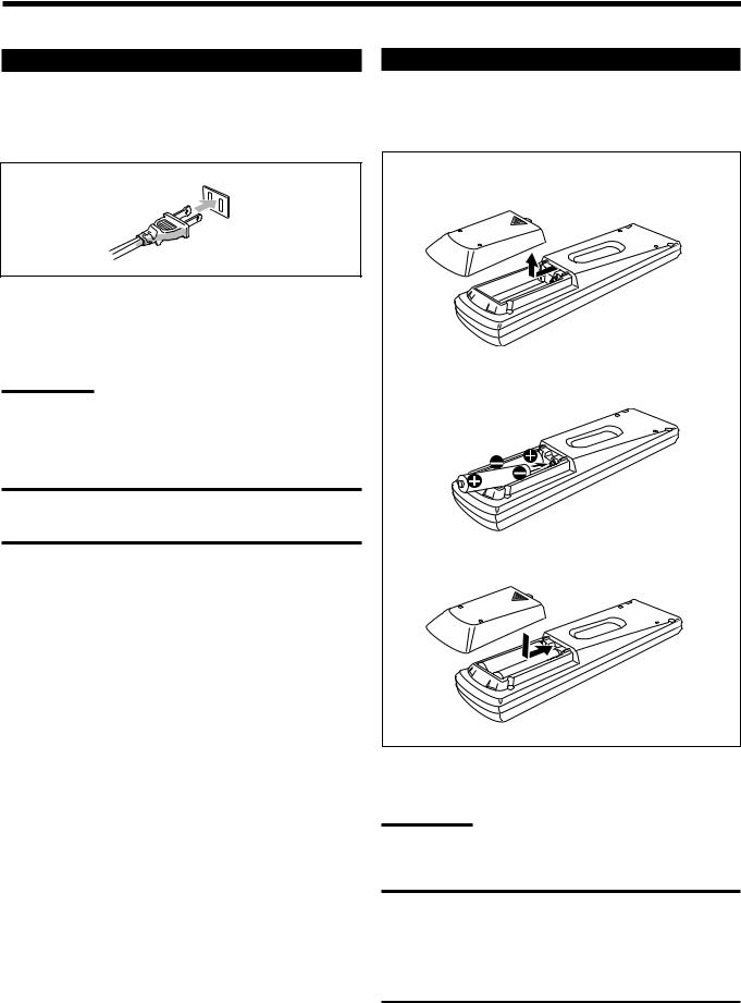
Putting Batteries in the Remote Control
Before using the remote control, put two supplied batteries first. When using the remote control, aim the remote control directly at the remote sensor on the receiver.
1.On the back of the remote control, remove the battery cover.
2.Insert batteries. Make sure to match the polarity: (+) to (+) and (–) to (–).
R6P(SUM-3)/AA(15F)
3. Replace the cover.
If the range or effectiveness of the remote control decreases, replace the batteries. Use two R6P(SUM-3)/AA(15F) type dry-cell batteries.
Note:
After replacing the batteries, set the manufacturers’ codes again (see page 54).
CAUTION:
Follow these precautions to avoid leaking or cracking cells:
•Place batteries in the remote control so they match the polarity:
(+) to (+) and (–) to (–).
•Use the correct type of batteries. Batteries that look similar may differ in voltage.
•Always replace both batteries at the same time.
•Do not expose batteries to heat or flame.
15

 Basic Operations
The following operations are commonly used when you play any sound sources.
Before using the remote control

 How to confirm the remote control operation mode
The display window on the remote control shows the following information when you press certain buttons on the remote control, so that you can confirm which operation you do.
Note:
A small amount of power is consumed in standby mode. To turn the power off completely, unplug the AC power cord.
Pressing one of the source selecting buttons, the source name selected appears on the display.
Buttons |
Indications |
FM/AM |
TUNER |
CD |
CD |
PHONO |
PHONO |
TAPE/MD |
TAPE |
DVD or DVD MULTI |
DVD |
CDR |
CDR |
USB |
USB |
TV/DBS |
TV |
VCR1 |
VCR1 |
VCR2 |
VCR2 |
VIDEO |
VIDEO |
A/V CONTROL RECEIVER
Ex.: When you press CD.
A/V CONTROL RECEIVER
Ex.: When you press USB.
Pressing SOUND before you adjust the sound |
A/V CONTROL RECEIVER |
|
effect, “SOUND” appears on the display. |
|
|
|
|
|
Pressing TEXT DISPLAY or MENU before |
|
|
you use on-screen menu or TEXT COMPU |
A/V CONTROL RECEIVER |
|
|
||
LINK, “MENU” appears on the display. |
|
|
|
|
|
Pressing CONTROL or CATV/DBS |
A/V CONTROL RECEIVER |
|
CONTROL before you operate an audio or |
|
|
video equipment connected to the receiver, |
Ex.: When you |
|
the remote control operation mode selected |
||
appears on the display (see pages 51 and 54). |
press CATV/ |
|
DBS CONTROL. |
||
|
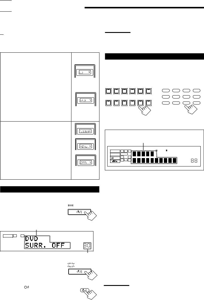
Turning On the Power
On the front panel:
Press STANDBY/ON  .
.
The STANDBY lamp goes off. The name of the current source and Surround/DSP mode appear on the display.
STANDBY
STANDBY/ON
Current source name and Surround/DSP mode appear
ANALOG |
L |
R |
|
|
SPEAKERS 1 |
VOLUME |
|
Current volume level appears
To turn off the power (into standby mode),


 STANDBY
press STANDBY/ON  again. The STANDBY lamp lights up.
STANDBY/ON
From the remote control:
Press AUDIO . |
AUDIO |
The STANDBY lamp on the front panel goes off. The name of the current source and Surround/DSP mode appear on the display.
To turn off the power (into standby mode), press AUDIO 
Selecting the Source to Play
Press one of the source selecting buttons.
The lamp on the front panel button for selected source lights up.
•The selected source name and the previously selected Surround/ DSP mode also appear on the display.
DVD MULTI |
DVD |
VCR 1 |
VCR 2 |
VIDEO |
TV SOUND/DBS |
DVD |
DVD MULTI |
CD |
FM/AM |
|
|
|
|
|
|
||||
|
|
|
|
|
SOURCE NAME |
TV/DBS |
VIDEO |
CDR |
PHONO |
PHONO |
CD |
CDR |
TAPE / MD |
USB AUDIO |
FM / AM |
VCR 1 |
VCR 2 |
TAPE/MD |
USB |
|
|
|
|
|
|
||||
|
|
|
SOURCE NAME |
|
|
|
|
|
|
On the front panel From the remote control
Selected source name and current
Surround/DSP mode appear
ANALOG |
L |
C |
R |
DGTL AUTO |
DVD MULTI |
PRO LOGIC |
TUNED |
STEREO |
|
|
DSP 3D–PHONIC MIDNIGHT MODE |
|
|||||
LINEAR PCM |
SUBWFR |
LFE |
|
|
|
|||
|
|
HEADPHONE DIGITAL EQ |
INPUT ATT |
ONETOUCH OPERATION |
||||
|
LS |
S |
RS |
|
|
|||
DIGITAL |
|
|
|
AUTO MUTING |
||||
|
SB |
|
|
|
|
|||
|
|
|
|
|
|
|
|
|
|
SPEAKERS 1 2 |
|
|
|
SLEEP VOLUME |
|||
DVD MULTI |
Select the DVD player for viewing the digital |
|
video disc using the analog discrete output |
|
mode (5.1-channel reproduction). |
|
To enjoy the DVD MULTI playback, see |
|
page 37. |
DVD |
Select the DVD player. |
VCR 1 |
Select the video component connected to the |
|
VCR 1 jacks. |
VCR 2 |
Select the video component connected to the |
|
VCR 2 jacks. |
VIDEO |
Select the video component connected to the |
|
VIDEO jacks. |
TV (SOUND)/DBS |
Select TV sounds (or the DBS tuner). |
PHONO * |
Select the turntable. |
CD * |
Select the CD player. |
CDR * |
Select the CD recorder. |
TAPE/MD * |
Select the cassette deck (or the MD recorder). |
USB (AUDIO) |
Select the personal computer (PC) connected |
|
to the USB terminal. |
FM/AM * |
Select an FM or AM broadcast. |
|
• Each time you press the button, the band |
|
alternates between FM and AM. |
Notes:
•When connecting an MD recorder (to the TAPE/MD jacks) and a DBS tuner (to the TV SOUND/DBS jacks), change the source names shown on the display. For details, see page 17.
•When you press one of the source selecting buttons on the remote control marked with an asterisk (*), the receiver automatically turns on.
again. The STANDBY lamp on the front panel lights up.
16
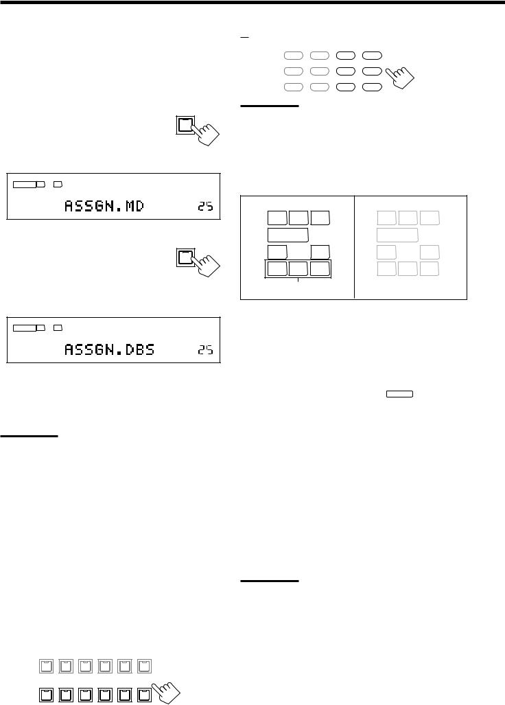
Changing the source name
When you have connected an MD recorder to the TAPE/MD jacks or a DBS tuner to the TV SOUND/DBS jacks on the rear panel, change the source name which will be shown on the display.
On the front panel ONLY:
When changing the source name from “TAPE” to “MD”:
1. Press TAPE/MD (SOURCE NAME).
• Make sure “TAPE” appears on the display.
2. Press and hold SOURCE NAME (TAPE/MD) until “ASSGN. MD” appears on the display.
ANALOG |
L |
R |
|
|
SPEAKERS 1 |
VOLUME |
|
When changing the source name from “TV” to “DBS”:
1. Press TV SOUND/DBS (SOURCE |
TV SOUND/DBS |
|
|
NAME). |
|
• Make sure “TV” appears on the display. SOURCE NAME
2.Press and hold SOURCE NAME (TV SOUND/DBS) until “ASSGN. DBS” appears on the display.
ANALOG |
L |
R |
|
|
SPEAKERS 1 |
VOLUME |
|
To change the source name to “TAPE” or “TV,” repeat the same procedure above—press and hold SOURCE NAME (TAPE/MD) to select “TAPE,” or press and hold SOURCE NAME (TV SOUND/ DBS) to select “TV.”
Note:
Without changing the source name, you can still use the connected components. However, there may be some inconvenience.
–“TAPE” or “TV” will appear on the display when you select the MD recorder or DBS tuner.
–You cannot use the digital input (see page 19) for the MD recorder.
–You cannot use the COMPU LINK remote control system (see page 43) to operate the MD recorder.
Selecting different sources for picture and sound
You can watch picture from a video component while listening to sound from another component.
Press one of the audio source selecting buttons— PHONO, CD, CDR, TAPE/MD, USB (AUDIO), FM/AM—while viewing the picture from a video component such as the VCR or DVD player, etc.
The lamp on the front panel button for the selected source lights up.
On the front panel:
DVD MULTI |
DVD |
VCR 1 |
VCR 2 |
VIDEO |
TV SOUND/DBS |
|
|
|
|
|
SOURCE NAME |
PHONO |
CD |
CDR |
TAPE / MD |
USB AUDIO |
FM / AM |
17 |
|
|
SOURCE NAME |
|
|
From the remote control:
DVD |
DVD MULTI |
CD |
FM/AM |
TV/DBS |
VIDEO |
CDR |
PHONO |
VCR 1 |
VCR 2 |
TAPE/MD |
USB |
Note:
Once you have selected a video source, pictures of the selected source are sent to the TV until you select another video source.
Speaker and signal indicators on the display
By checking the following indicators, you can easily confirm which speakers you are activating and which signals are coming into this receiver from the source.
Speaker indicators (white) |
Signal indicators (red) |
||||
L |
C |
R |
L |
C |
R |
SUBWFR |
LFE |
SUBWFR LFE |
|||
LS |
S |
RS |
LS |
S |
RS |
|
SB |
|
|
SB |
|
Surround back speaker |
|
|
|
||
indicators * |
|
|
|
||
The speaker indicators light up—:
• When the corresponding speakers are set to “LARGE” or “SMALL” (see “1 Setting the Speakers” on page 22) and are also required for the Surround/DSP mode currently selected.
*If you have selected “1SPK” for the surround back speaker quantity (see page 22), the center surround back speaker indicator lights up. If you have selected “2SPK,” the left and right surround back speaker indicators light up.
•When “SUBWOOFER” is set to “YES,” SUBWFR lights up. (See “1 Setting the Speakers” on page 22.)
The signal indicators light up to indicate the incoming signals. L : • When digital input is selected: Lights up when the left
channel signal comes in.
• When analog input is selected: Always lights up.
R : • When digital input is selected: Lights up when the right channel signal comes in.
• When analog input is selected: Always lights up.
C : Lights up when the center channel signal comes in. LFE : Lights up when the LFE channel signal comes in.
LS : Lights up when the left surround channel signal comes in. RS : Lights up when the right surround channel signal comes in. S : When the monaural rear channel signal or 2 channel Dolby
Surround encoded signal comes in.
SB : Lights up when the surround back channel signal comes in.
Note:
When “DVD MULTI” is selected as the source, “L,” “C,” “R,” “LFE,” “LS” and “RS” light up.
Adjusting the Volume
On the front panel:
To increase the volume, turn MASTER |
MASTER VOLUME |
|
|
||
VOLUME clockwise. |
|
|
To decrease the volume, turn it |
|
|
counterclockwise. |
|
|
From the remote control: |
+ |
|
To increase the volume, press VOLUME +. |
||
|
||
To decrease the volume, press VOLUME –. |
VOLUME |
|
|
||
|
− |
CAUTION:
Always set the volume to the minimum before starting any sources. If the volume is set at its high level, the sudden blast of sound energy can permanently damage your hearing and/or ruin your speakers.
Notes:
•The volume level can be adjusted within the range of “0” (minimum) to “70” (maximum).
•If you set One Touch Operation to “ON” (see page 26), you do not have to adjust the volume level each time you change the source. It is automatically set to the stored level.
Selecting the Front Speakers
IMPORTANT:
You can activate two pairs of the front speakers at the same time only when the SPEAKER LOAD SELECTOR switch on the rear panel is set to the “HIGH” position and when signals are sent only to front speakers. Otherwise, activating one pair of the speakers deactivates the other.
On the front panel ONLY:
When you have connected two pairs of the front speakers, you can select which to use.
To use the speakers connected to the |
SPEAKERS ON/OFF |
FRONT SPEAKERS 1 terminals, press |
1 |
SPEAKERS ON/OFF 1 so that the
SPEAKERS 1 indicator lights up on the
2
display. Make sure that the SPEAKERS 2 indicator is not lit on the display.
To use the speakers connected to the FRONT SPEAKERS 2 terminals, press SPEAKERS ON/OFF 2 so that SPEAKERS 2 indicator lights up on the display. Make sure that the SPEAKERS 1 indicator is not lit on the display.
To use both sets of the speakers, press SPEAKERS ON/OFF 1 and SPEAKERS ON/OFF 2 so that the SPEAKERS 1 and SPEAKERS 2 indicators light up on the display.
To use neither sets of the speakers, press SPEAKERS ON/OFF 1 and SPEAKERS ON/OFF 2 so that the SPEAKERS 1 and SPEAKERS 2 indicators disappear from the display.
The HEADPHONE indicator lights up and “HEADPHONE” appears on the display.
•Activating the speakers turns on the Surround and DSP modes previously selected.
Listening Only with Headphones
You can listen with the headphones without deactivating both pairs of speakers by connecting a pair of headphones to the PHONES jack on the front panel. If you want to use a pair of headphones without outputting sounds from the front speakers, you must turn off both pairs of the front speakers as mentioned above.
HEADPHONE mode
When using the headphones, the following signals are output regardless of your speaker setting:
—For 2 channel software, the front left and right channel signals are output directly from the headphones.
—For multi-channel software, the front left and right, center, and surround channel signals are down-mixed and then output from the headphones.
•If a DSP mode is activated, you can enjoy the DSP effects. “3D H.PHONE” appears on the display and the DSP indicator lights up on the display. (See page 34.)
Note:
In the following cases, the speakers connected to the FRONT
SPEAKERS 2 terminals are deactivated even if both pairs of the front speakers are activated.
–If you select “DVD MULTI” as the source.
–If you select any of the Surround/DSP modes which activates the center and/or surround speaker(s).
CAUTION:
Be sure to turn down the volume:
•Before connecting or putting on headphones, as its high volume can damage both the headphones and your hearing.
•Before turning on speakers again, as its high volume may output from the speakers.
18
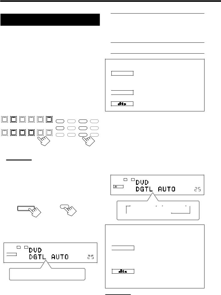
Selecting the Analog or Digital Input
Mode
When you have connected digital source components using the digital terminals (see page 13), you need to change the input mode for these components to the appropriate digital input mode correctly—DGTL AUTO, DGTL DTS, or DGTL D.D.
Before you start, remember...
The digital input (DIGITAL IN) terminal setting should be correctly done for the sources you want to select the digital input mode for (see “6 Setting the Digital Input (DIGITAL IN) Terminals” on page 25). Without setting this digital input terminal correctly, you cannot change the input mode from analog input to digital input even if you follow the procedure below.
1.Press one of the source selecting buttons—DVD, TV (SOUND)/DBS, CD, CDR, or TAPE/MD—for which you want to change the input mode.
The lamp on the front panel button for the selected source lights up.
DVD MULTI |
DVD |
VCR 1 |
VCR 2 |
VIDEO |
TV SOUND/DBS |
|
|
|
|
|
|
|
|
DVD |
DVD MULTI |
CD |
FM/AM |
|
|
|
|
|
SOURCE NAME |
VIDEO |
CDR |
PHONO |
|
|
|
|
|
TV/DBS |
|||
PHONO |
CD |
CDR |
TAPE / MD |
USB AUDIO |
FM / AM |
|
|
|
|
|
|
|
|
VCR 1 |
VCR 2 |
TAPE/MD |
USB |
|
|
|
SOURCE NAME |
|
|
|
|
|
On the front panel From the remote control
Note:
If “TAPE” has been assigned as the source name to the TAPE/MD button when using an MD recorder, it does not work in this step.
To change the source name, see “Changing the source name” on page 17.
2.Press INPUT ANALOG/DIGITAL (INPUT ATT)—or ANALOG/DIGITAL INPUT on the remote control— briefly to change the input mode.
INPUT |
|
ANALOG/DIGITAL |
ANALOG/DIGITAL |
|
INPUT |
INPUT ATT |
|
On the front panel |
From the remote control |
•Each time you press the button, the input mode changes as follows:
L R DGTL AUTO

 DIGITAL
SPEAKERS 1 |
VOLUME |
DGTL AUTO 
 ANALOG
(Digital)
DGTL AUTO: Select this for the digital input mode. The receiver automatically detects the incoming signals.
The DGTL AUTO indicator lights up on the display, and the digital signal format indicators for the detected signals also light up.
ANALOG: Select this for the analog input mode. The ANALOG indicator lights up.
When selecting “DGTL AUTO,” the following indicators showing detected signals light up on the display.
LINEAR PCM : Lights up when Linear PCM signals come in.
LINEAR PCM : Lights up when the digital signals are not recognized.

 DIGITAL : Lights up when Dolby Digital or Dolby Digital EX signals come in.
:Lights up when DTS Surround or DTS-ES signals come in.
When playing a software encoded with the Dolby Digital or DTS Digital Surround, the following symptoms may occur:
•Sound does not come out at the beginning of playback.
•Noise comes out while chapters or tracks are being searched for or skipped over.
1.Press INPUT ANALOG/DIGITAL (INPUT ATT) or ANALOG/DIGITAL INPUT on the remote control.
• “DGTL AUTO” appears on the display.
2.Press CONTROL UP 5 or DOWN ∞ on the front panel to select “DGTL D.D” or “DGTL DTS” while “DGTL AUTO” still remains on the display.
•Each time you press the button, the input mode changes as follows:
L |
R |
DGTL |
AUTO |
DIGITAL |
|
|
|
SPEAKERS 1 |
|
VOLUME |
|
DGTL AUTO |
|
DGTL D.D |
|
|
|
||
(Digital) |
(Digital Dolby Digital) |
||
 DGTL DTS
(Digital)
When selecting “DGTL D.D” or “DGTL DTS,” the following indicators showing detected signals light up on the display.
DGTL |
: Always lights up. |
When selecting “DGTL D.D”

 DIGITAL : • Lights up when Dolby Digital signals come in.
•The frame flashes when Dolby Digital signals are not recognized.
When selecting “DGTL DTS”
: • Lights up when DTS Digital Surround signals come in.
•The frame flashes when DTS Digital Surround signals are not recognized.
Note:
When you turn off the power or select another source, “DGTL D.D” and “DGTL DTS” settings are canceled and the digital input mode is automatically reset to “DGTL AUTO.”
19
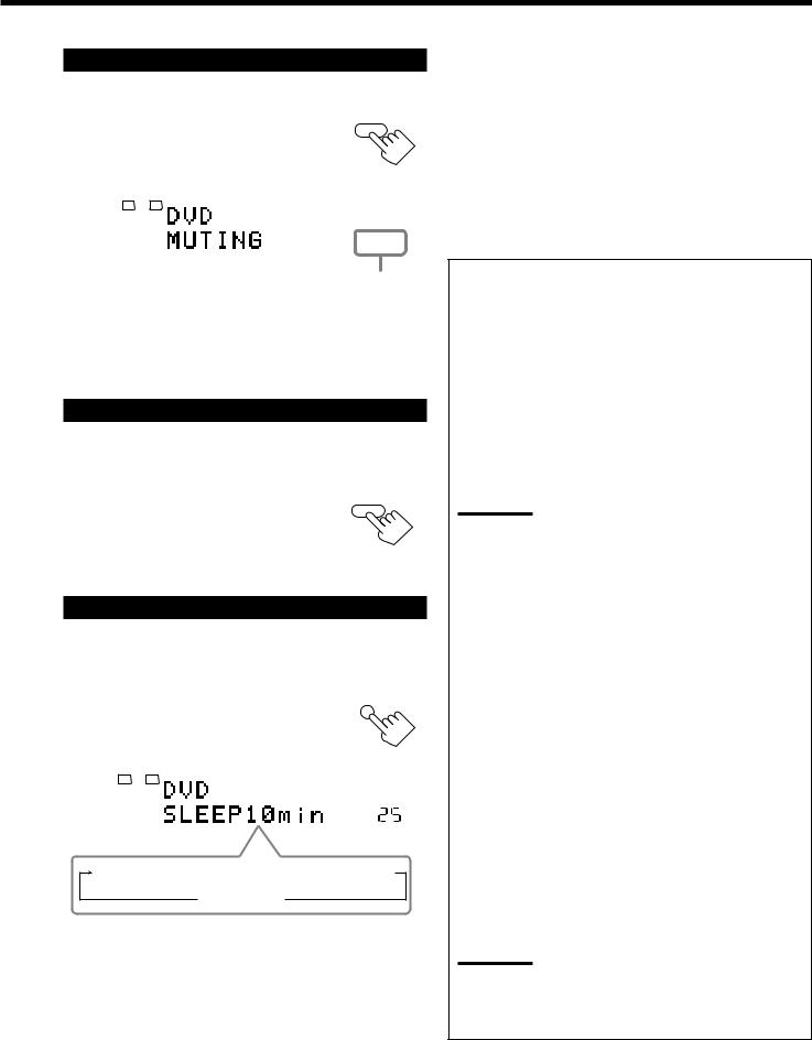
Muting the Sound
From the remote control ONLY:
Press MUTING to mute the sound through |
MUTING |
||||||
all speakers and headphones connected. |
|
|
|||||
“MUTING” appears on the display and the volume |
|
|
|||||
turns off (the volume level indicator goes off). |
|
|
|
||||
|
|
|
|
|
|
|
|
|
|
|
L |
R |
|
|
|
|
|
ANALOG |
|
|
|
||
|
|
|
SPEAKERS 1 |
|
|
|
|
|
|
|
|
|
|||
|
|
|
|
|
|
||
|
|
|
|
|
|
|
|
|
Ex.: When the source is “DVD.” |
The volume level |
|||||
|
|
|
|
|
indicator goes off. |
||
To restore the sound, press MUTING again.
•Turning MASTER VOLUME on the front panel or pressing VOLUME +/– on the remote control also restores the sound.
Changing the Display Brightness
You can dim the display.
From the remote control ONLY:
Press DIMMER. |
DIMMER |
• Each time you press the button, the display dims and brightens alternately.
Using the Sleep Timer
Using the Sleep Timer, you can fall asleep while listening to music.
From the remote control ONLY:
Press SLEEP repeatedly. |
SLEEP |
||||
The SLEEP indicator lights up on the display, and |
|
||||
the shut-off time changes in 10 minutes intervals: |
|
||||
|
|
|
|
|
|
|
|
|
L |
R |
|
|
|
ANALOG |
|
||
|
|
|
SPEAKERS 1 |
SLEEP VOLUME |
|
|
|
|
|
|
|
10  20
20  30
30  40
40  50
50  60
60  70
70  80
80  90
90
0 (Canceled)
Ex.: When the source is “DVD.”
When the shut-off time comes:
The receiver turns off automatically.
To check or change the time remaining until the shut-off time:
Press SLEEP once.
The remaining time until the shut-off time appears in minutes.
• To change the shut-off time, press SLEEP repeatedly.
To cancel the Sleep Timer:
Press SLEEP repeatedly until “SLEEP 0min” appears on the display. (The SLEEP indicator goes off.)
•Turning off the power also cancels the Sleep Timer.
Recording a source
For analog-to-analog recording
You can record any analog source through the receiver to—
•the cassette deck (or MD recorder) connected to the TAPE/MD jacks,
•the VCRs connected to the VCR 1 and VCR 2 jacks, and
•the CD recorder connected to the CDR jacks
—at the same time.
For digital-to-digital recording
You can record the currently selected digital input source through the receiver to a digital recording device connected to the DIGITAL OUT terminal.
Notes:
•Analog-to-digital and digital-to-analog recordings are not possible.
•The output volume level, Midnight Mode (see page 24), Bass
Boost (see page 31), digital equalization (see page 39),
Surround modes and DSP modes (see pages 32 to 36) cannot affect the recording.
•The test tone signal (see pages 40 and 41) does not come out through the DIGITAL OUT terminal.
Basic adjustment auto memory
This receiver memorizes sound settings for each source—
•when you turn off the power,
•when you change the source, and
•when you assign the source name (see page 19).
When you change the source, the memorized settings for the newly selected source are automatically recalled.
The following can be stored for each source:
•Analog/digital input mode (see page 19)
•Input attenuator mode (see page 30)
•Analog Direct (see page 30)
•Speaker channel output levels (see pages 40 and 41)
•Digital equalization pattern (see page 39)
•Sound parameters (see page 42)
•Surround and DSP mode selection (see pages 35 and 36)
•Bass Boost setting (see page 31)
Notes:
•If the source is FM or AM, you can assign a different setting for each band.
•If you want to memorize the volume level with the above settings, set “ONE TOUCH (OPR)” to “ON” (see page 26).
20
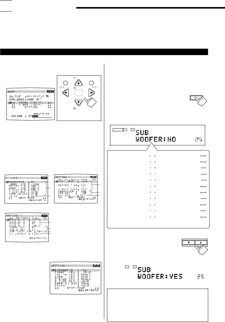

 Basic Settings
Some of the following settings are required after connecting and positioning your speakers while others will make operations easier.
•When performing the basic settings, it is recommended to use the remote control so that you can show the on-screen display on the TV.
•When using the buttons on the front panel, you can perform the same settings. (The following on-screen display cannot be shown if you use the buttons on the front panel.)
•The on-screen display will disappear if no operation is done for about 1 minute.
Basic Procedure
Ex. When setting the subwoofer information
Using the on-screen display (through the remote control):
1. Press MENU. |
|
PLAY |
|
|
The MENU screen appears on |
MENU |
EXIT |
||
|
||||
the TV. |
/REW PAUSE |
FF/ |
||
|
||||
|
|
SET |
|
|
|
DOWN – TUNING – UP |
|||
|
|
STOP |
CONTROL |
|
|
On-screen operating |
|||
|
|
buttons |
||
2. Press 5 or ∞ to move  to “SETTING,” then press 2 or 3.
SETTING 1 menu showing setting items appears on the TV.
•The item pointed by  is also shown on the display on the unit.
3.Press 5 or ∞ to move  to “SUBWOOFER.”
•To go to the next screen, press ∞ continuously.
•To go back to the previous screen, press 5 continuously.


 3 1
3 1 


|
4 |
2 |
5 |
SETTING 1 menu |
SETTING 2 menu |
6
7
8
9
SETTING 3 menu
For details about each setting item (1 to 9), see pages 22 to 26.
4. Press 2 or 3 to select a setting you want to use.
In this example, the subwoofer information is set to “YES” to output bass sound through the subwoofer.
5.When you finish, press EXIT repeatedly until the menu disappears from the TV.
21
On the front panel:
Before you start, remember....
There is a time limit in doing the following steps. If the setting is canceled before you finish, start from step 1 again.
1. Press SETTING repeatedly until SETTING
“SUB WOOFER” appears on the display.
Each time you press the button, the setting items change as follows.
•For details about each setting item (1 to 9), see pages 22 to 26.
ANALOG |
L |
R |
|
|
SPEAKERS 1 |
VOLUME |
|
SUB WOOFER:NO (1) |
|
|
|
|
|
FRONT SPK:LARGE (1) |
|
|
|||||||
CNTR SPK:SMALL (1) |
|
|
|
|
|
SURR SPK:SMALL (1) |
|
|
|
||||||
SBACK SPK:SMALL (1) |
|
|
|
|
|
SBACK OUT:2SPK (1) |
|
|
|
|
|||||
SURR CH:SURR (1) |
|
|
|
|
|
EX/ES:AUTO (2) |
|
|
|
|
|
||||
DIST UNIT:meter (3) |
|
|
|
|
|
FRONT DIST:3.0m (3) |
|
|
|
|
|
|
|||
CNTR DIST:3.0m (3) |
|
|
|
|
|
SURR DIST:3.0m (3) |
|
|
|
|
|
|
|||
SBACK DIST:3.0m (3) |
|
|
|
|
|
CROSS OVER:100Hz (4) |
|
|
|
|
|
|
|||
LFE ATT:0dB (4) |
|
|
|
|
|
MID NIGHT:OFF (5) |
|
|
|
|
|
|
|||
DGTL COAX 1:DVD (6) |
|
|
|
|
|
|
2:CD 3:TV 4:CDR (6) |
|
|
|
|
|
|
||
VIDEO DVD:S/C (7) |
|
|
|
|
|
VIDEO DBS:S/C (7) |
|
|
|
|
|
|
|||
ONE TOUCH:OFF (8) |
|
|
|
|
|
FL DISP:TEXT (9) |
|
|
|
|
|
|
|||
(Back to the beginning) |
|
|
|
|
|
|
|
2. Press CONTROL UP 5 or |
CONTROL |
||||
DOWN UP |
|||||
|
DOWN ∞ to select a setting you |
||||
|
|
||||
|
want to use. |
|
|||
|
In this example, the subwoofer information is |
|
|||
|
set to “YES” to output bass sound through the |
|
|||
|
subwoofer. |
|
|||
|
|
|
|
|
|
|
|
|
L R |
|
|
|
|
ANALOG |
|
||
|
|
|
SPEAKERS 1 |
VOLUME |
|
|
|
|
|
|
|
NOTICE—
•Items shown on the on-screen display and on the front panel display in this section are initial values when shipped from the factory.
•Some of the items cannot be shown or cannot be adjusted according to currently selected settings. (For details, see the respective explanation.)
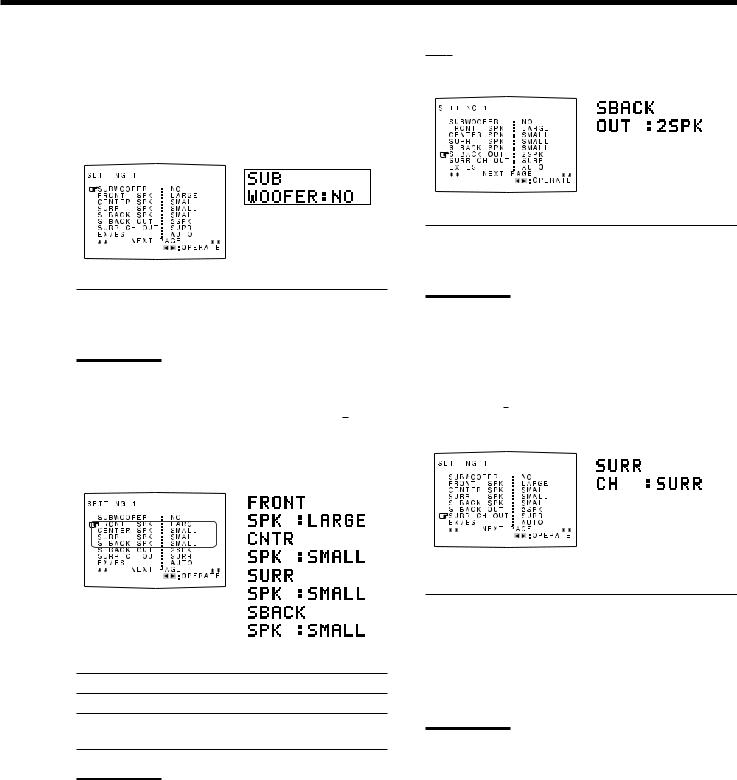
1 Setting the Speakers
To obtain the best possible surround sound from the Surround and DSP modes, you have to register the setting about the speaker arrangement after all connections are completed.
7 Subwoofer setting—SUBWOOFER
[On-screen display] |
[Front panel] |
||
|
|
|
|
|
|
|
|
|
|
|
|
|
|
|
|
7Surround back speakers quantity—S BACK (SBACK) OUT
[On-screen display] |
[Front panel] |
|||
|
|
|
|
|
|
|
|
|
|
|
|
|
|
|
|
|
|
|
|
|
|
|
|
|
|
|
|
|
|
Select whether you have connected a subwoofer or not.
YES |
: Select this when a subwoofer is connected. |
NO |
: Select this when no subwoofer is used. |
|
|
Note:
If you have selected “NO” for the subwoofer, you cannot use SUBWOOFER OUT ON/OFF on the front panel.
7Sizes for front speakers, center speaker, surround speakers, and surround back speakers–—FRONT SPK, CENTER (CNTR) SPK, SURR SPK, S BACK (SBACK) SPK
[On-screen display] |
|
[Front panel] |
||
|
|
|
|
|
|
|
|
|
|
|
|
|
|
|
|
|
|
|
|
|
|
|
|
|
|
|
|
|
|
|
|
|
|
|
|
|
|
|
|
|
|
|
|
|
|
|
|
|
|
|
|
|
|
|
Select the sizes for each connected speaker.
LARGE : Select this when the speaker size is relatively large.
SMALL : Select this when the speaker size is relatively small.
NONE : Select this when you have not connected a speaker. (Not selectable for the front speakers)
Notes:
•Keep the following comments in mind as reference when adjusting.
–If the size of the cone speaker unit built in your speaker is larger than 12 cm (4 3/4 inches), select “LARGE,” and if it is smaller than 12 cm (4 3/4 inches), select “SMALL.”
•If you have selected “NO” for the subwoofer setting, you can only select “LARGE” for the front speakers.
•If you have selected “SMALL” for the front speakers, you cannot select “LARGE” for the center, surround, and surround back speakers.
•If you have selected “SMALL” for the surround speakers, you cannot select “LARGE” for the surround back speakers.
•If you have selected “NONE” for the surround speakers, the surround back speakers are fixed to “NONE.”
Select the surround back speakers quantity.
2SPK |
: Select this to use 2 surround back speakers. |
1SPK |
: Select this to use 1 surround back speaker. |
|
|
Notes:
•If you have selected “NONE” for the surround back speakers (see the left), this setting cannot be available.
•If you have selected “1SPK” for the surround back speaker quantity, connect the surround back speaker to the PRE OUT SURR BACK L (left) jack.
7Selecting surround speakers to use—SURR CH (OUT)
[On-screen display] |
|
[Front panel] |
||
|
|
|
|
|
|
|
|
|
|
|
|
|
|
|
|
|
|
|
|
|
|
|
|
|
Select the surround speakers to activate when playing back 5.1- multi-channel software.
SURR |
: Select this to use only the left and right |
|
surround speakers. |
|
|
SBACK |
: Select this to use only the surround back |
|
speakers. |
|
|
SURR+SBK |
: Select this to use both the surround speakers |
(S+SBK) |
and surround back speakers. |
|
|
Notes:
•If you have selected “NONE” for the surround back speakers (see the left), this setting is skipped.
•If you have selected “1SPK” for the surround back speaker quantity, this setting is skipped. The surround channels’ signals are output through the surround speakers.
•This setting is ignored when performing 6.1-channel reproduction.
22
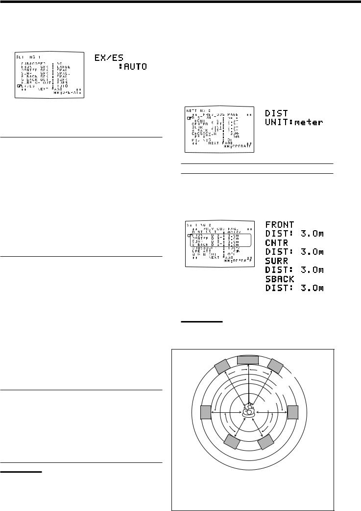
2Selecting Channel Numbers to Reproduce Multi-channel Digital Software—EX/ES
[On-screen display] |
[Front panel] |
|||
|
|
|
|
|
|
|
|
|
|
|
|
|
|
|
|
|
|
|
|
|
|
|
|
|
You can select 5.1-channel reproduction or 6.1-channel reproduction when playing back multi-channel (more than 5.1-channel) digital software with setting the surround back speakers to “LARGE” or “SMALL” (see page 22). “AUTO” is initial setting.
AUTO : Select this to reproduce signals originally recorded as marked on the software such as  or
or 
 .
.
•When playing back Dolby Digital EX software (bearing
the mark  ,) “DOLBY D EX (Dolby Digital EX)” activates using the surround back speaker(s).
•When playing back Dolby Digital 5.1-channel software, “DOLBY D (Dolby Digital)” activates without using the surround back speaker(s).
•When playing back DTS-ES Discrete software (bearing the mark 
 ,) “ES DSCRETE (DTS-ES Discrete)” activates using the surround back speaker(s).
•When playing back DTS-ES Matrix software (bearing the mark 
 ,) “ES MATRIX (DTS-ES Matrix)” activates using the surround back speaker(s).
•When playing back DTS Digital Surround 5.1-channel software, “DTS (DTS Digital Surround)” activates without using the surround back speaker(s).
ON |
: Select this to activate 6.1-channel reproduction using the |
|
surround back speaker(s). |
•When playing back Dolby Digital EX software (bearing
the mark  ,) “DOLBY D EX (Dolby Digital EX)” activates using the surround back speaker(s).
•When playing back Dolby Digital 5.1-channel software, “DOLBY D EX (Dolby Digital EX)” activates using the surround back speaker(s). Surround back channels are reproduced using digital matrix processing.
•When playing back DTS-ES Discrete software (bearing the mark  ,) “ES DSCRETE (DTS-ES Discrete)” activates using the surround back speaker(s).
•When playing back DTS-ES Matrix software (bearing the mark  ,) “ES MATRIX (DTS-ES Matrix)” activates using the surround back speaker(s).
•When playing back DTS Digital Surround 5.1-channel software, “DTS NEO:6” activates using the surround back speaker(s). Surround back channels are reproduced using digital matrix processing.
OFF : Select this to activate 5.1-channel reproduction without using the surround back speaker(s).
•When playing back Dolby Digital EX software (bearing
the mark  ) or DTS-ES software (bearing the mark
 ,) the surround back signals are output from the surround speakers mixed with the surround signals.
•When playing back Dolby Digital or DTS Digital Surround 5.1-channel software, conventional “DOLBY D (Dolby Digital)” or “DTS (DTS Digital Surround)” activates.
Note:
If you have selected “NONE” for the surround back speakers (see page 22), you cannot select this setting. The 6.1-channel and 5.1- channel software are played back as “OFF” is selected.
23
3 Setting the Speaker Distance
The distance from your listening point to the speakers is another important element to obtain the best possible sound of the Surround and DSP modes. You need to set the distance from your listening point to the speakers.
By referring to the speaker distance setting, this unit automatically sets the delay time of the sound through each speaker so that sounds through all the speakers can reach you at the same time.
7 Measuring unit—UNIT
[On-screen display] |
|
[Front panel] |
|||||
|
|
|
|
|
|
|
|
|
|
|
|
|
|
|
|
|
|
|
|
|
|
|
|
|
|
|
|
|
|
|
|
|
|
|
|
|
|
|
|
|
|
|
|
|
|
|
|
|
|
|
|
|
|
|
|
|
|
|
|
|
|
|
|
Select which unit you use.
meter : Select this to set the distance in meters.
feet |
: Select this to set the distance in feet. |
7Speaker distance—FRONT DIST, CENTER (CNTR) DIST, SURR DIST, S BACK (SBACK) DIST
[On-screen display] |
|
[Front panel] |
||||||
|
|
|
|
|
|
|
|
|
|
|
|
|
|
|
|
|
|
|
|
|
|
|
|
|
|
|
|
|
|
|
|
|
|
|
|
|
|
|
|
|
|
|
|
|
|
|
|
|
|
|
|
|
|
|
|
|
|
|
|
|
|
|
|
|
|
|
|
|
|
|
|
|
|
|
|
|
|
|
|
|
|
|
|
|
|
|
|
|
|
|
|
|
|
|
|
|
|
|
|
|
|
|
|
|
|
|
|
|
|
|
|
|
|
|
|
|
|
|
|
|
|
|
|
|
|
|
|
|
|
|
|
|
|
|
|
|
|
|
|
|
|
|
|
|
|
|
|
|
|
|
|
|
Set the distance from the listening point within the range of 0.3 m (1 ft) to 9.0 m (30 ft), in 0.3 m (1 ft) intervals.
Notes:
•You cannot set the speaker distance for the speakers you have selected “NONE” (see page 22).
•This setting is not valid for the DVD MULTI playback mode.
|
C |
|
L |
R |
3.3 m |
30˚ |
30˚ |
|
|
|
(11 ft) |
|
|
3.0 m |
|
|
(10 ft) |
90˚ |
90˚ |
2.7 m |
(9 ft) |
||
|
2.4 m |
|
|
(8 ft) |
|
|
2.1 m |
|
LS |
(7 ft) |
RS |
|
||
60˚ |
60˚ |
|
LSB |
RSB |
|
EX. In the above case, set the speaker distance as follows:
FRONT DIST |
: |
3.0 m or 10 ft |
|
CENTER (CNTR) DIST |
: |
3.0 m or 10 ft |
|
SURR DIST |
: |
2.7 m |
or 9 ft |
S BACK (SBACK) DIST |
: |
2.4 m |
or 8 ft |
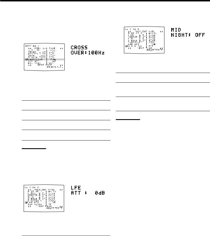
4 Setting the Bass Sounds |
|
5 Setting the Dynamic Range—MID NIGHT |
|||||||||||||||||
You can adjust subwoofer and bass sounds precisely according to |
|
[On-screen display] |
[Front panel] |
||||||||||||||||
your preference. |
|
|
|||||||||||||||||
|
|
|
|
|
|
|
|
|
|
|
|||||||||
7 Crossover frequency—CROSSOVER |
|
|
|
|
|
|
|
|
|
|
|||||||||
|
|
|
|
|
|
|
|
|
|
||||||||||
|
|
|
|
|
|
|
|
|
|
||||||||||
|
|
|
|
|
|
|
|
|
|
||||||||||
|
|
|
|
|
|
|
|
|
|
||||||||||
|
|
|
|
|
|
|
|
|
|
||||||||||
|
|
|
|
|
|
|
|
|
|
||||||||||
|
|
[On-screen display] |
[Front panel] |
|
|
|
|
|
|
|
|
|
|
||||||
|
|
|
|
|
|
|
|
|
|
|
|
||||||||
|
|
|
|
|
|
|
|
|
|
|
|
||||||||
|
|
|
|
|
|
|
|
|
|
|
|
||||||||
|
|
|
|
|
|
|
|
|
|
|
|
|
|
|
|
|
|
|
|
|
|
|
|
|
|
|
|
|
|
|
|
|
|
|
|
|
|
|
|
|
|
|
|
|
|
|
|
|
|
|
|
|
|
|
|
|
|
|
|
|
|
|
|
|
|
|
|
|
|
|
|
|
|
|
|
|
|
|
|
|
|
|
|
|
|
|
|
|
|
|
|
|
|
|
|
|
|
|
|
|
|
|
|
|
|
|
|
|
|
|
|
|
|
|
|
|
|
|
|
|
|
|
|
|
|
|
|
|
|
|
|
|
|
|
|
|
|
|
|
|
|
|
|
|
|
|
|
|
|
|
|
|
|
|
|
|
|
|
|
|
|
|
|
|
|
|
|
|
|
|
|
|
|
|
|
|
|
|
|
|
|
|
|
|
|
|
|
|
|
|
|
|
|
|
|
|
|
|
|
|
|
|
|
|
|
|
|
|
|
|
|
|
|
|
|
|
|
|
|
|
|
|
|
|
|
|
|
|
|
|
|
|
|
|
|
|
|
|
|
When you use a subwoofer, you can select the cutoff frequency for the small speakers used.
Select one of the crossover frequency levels from “80Hz,” “100Hz,” “120Hz” and “150Hz” according to the size of the small speaker connected.
80Hz : Select this frequency when the cone speaker unit built in the speaker is about 12 cm (4 3/4 inches).
100Hz : Select this frequency when the cone speaker unit built in the speaker is about 10 cm (3 15/16 inches).
120Hz : Select this frequency when the cone speaker unit built in the speaker is about 8 cm (3 3/16 inches).
150Hz : Select this frequency when the cone speaker unit built in the speaker is about 6 cm (2 3/8 inches).
Notes:
.• If you have selected “LARGE” for all activated speakers (see page 22), this function is fixed to “OFF.”
•Crossover frequency is not valid for the DVD MULTI playback,
All Channel Stereo and 3D HEADPHONE mode.
7 Low frequency effect attenuator—LFE ATT
[On-screen display] |
[Front panel] |
||||||
|
|
|
|
|
|
|
|
|
|
|
|
|
|
|
|
|
|
|
|
|
|
|
|
|
|
|
|
|
|
|
|
|
|
|
|
|
|
|
|
|
|
|
|
|
|
|
|
|
|
|
|
|
|
|
|
|
|
|
|
|
|
|
|
|
|
|
|
|
|
|
|
|
|
|
|
|
|
|
|
|
|
|
|
|
|
|
|
|
|
|
|
|
|
|
|
|
|
|
|
|
|
|
|
|
|
|
|
|
|
|
|
|
|
|
|
|
|
|
|
If the bass sound is distorted while playing back software encoded with Dolby Digital or DTS Surround, set the LFE level to eliminate distortion.
Select one of the following:
0dB |
: Normally select this. |
−10dB |
: Select this when the bass sound is distorted. |
|
|
You can enjoy a powerful sound at night using the Midnight Mode.
Select one of the following:
1: Select this when you want to reduce the dynamic range. The MIDNIGHT MODE indicator lights up on the display.
2: Select this when you want to apply the compression effect (useful at midnight). The MIDNIGHT MODE indicator lights up on the display.
OFF : Select this when you want to enjoy surround with its full dynamic range (no effect applied). The MIDNIGHT MODE indicator goes off from the display.
Notes:
•If Analog Direct is in use, Midnight Mode is temporarily canceled.
•Midnight Mode is not valid for DVD MULTI playback mode even though the setting is adjustable.
24
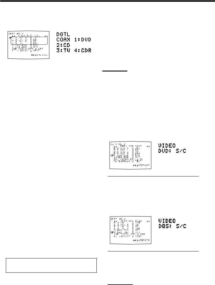
6Setting the Digital Input (DIGITAL IN) Terminals
[On-screen display] |
[Front panel] |
|||||||
|
|
|
|
|
|
|
|
|
|
|
|
|
|
|
|
|
|
|
|
|
|
|
|
|
|
|
|
|
|
|
|
|
|
|
|
|
|
|
|
|
|
|
|
|
|
|
|
|
|
|
|
|
|
|
|
|
|
|
|
|
|
|
|
|
|
|
|
|
|
|
|
|
|
|
|
|
|
|
|
|
|
|
|
|
|
|
|
|
|
|
|
|
|
|
|
|
|
|
|
|
|
|
|
|
|
|
|
|
|
|
|
|
|
|
|
|
When you use the digital input terminals, you have to register which components you have connected to the digital input terminals.
7 Digital coaxial terminal—DIGITAL 1 (DGTL COAX 1)
Set the component connected to the digital coaxial terminal (DIGITAL IN 1)—DVD, MD**, CDR, TV (or DBS*) or CD.
*If you have changed the source name from “TV” to “DBS,” “DBS” appears (see page 17).
**If you want to connect an MD recorder to the digital input terminal, change the source name to “MD” from “TAPE” (see page 17).
7Digital optical terminals—DIGITAL 2, DIGITAL 3 and DIGITAL 4
Set the components connected to the digital optical terminals (DIGITAL IN 2 – 4).
•Each time you press 2 or 3 on the remote control or CONTROL UP 5 or DOWN ∞ on the front panel, the digital component names change as follows:
When “DIGITAL 1 (DGTL COAX 1)” is set to “DVD”
2: CD 3: TV (or DBS* ) 4: CDR |
“ |
2: CD 3: TV (or DBS*) 4: MD** |
“ |
2: CD 3: MD** 4: CDR |
“ |
2: MD** 3: TV (or DBS* ) 4: CDR |
“ |
(back to the beginning) |
|
|
|
When “DIGITAL 1 (DGTL COAX 1)” is set to “MD”**
2: CD 3: TV (or DBS*) 4: CDR |
“ |
2: CD 3: TV (or DBS*) 4: DVD |
“ |
2: CD 3: DVD 4: CDR |
“ |
2: DVD 3: TV (or DBS*) 4: CDR |
“ |
(back to the beginning) |
|
|
|
When “DIGITAL 1 (DGTL COAX 1)” is set to “CDR”
2: CD 3: TV (or DBS*) 4: DVD |
“ |
2: CD 3: TV (or DBS*) 4: MD** |
“ |
2: CD 3: MD** 4: DVD |
“ |
2: MD** 3: TV (or DBS*) 4: DVD |
“ |
(back to the beginning) |
|
|
|
When “DIGITAL 1 (DGTL COAX 1)” is set to “TV” or “DBS”*
2: CD 3: DVD 4: CDR “2: CD 3: DVD 4: MD** “ 2: CD 3: MD** 4: CDR “ 2: MD** 3: DVD 4: CDR “ (back to the beginning)
When “DIGITAL 1 (DGTL COAX 1)” is set to “CD”
2: DVD 3: TV (or DBS*) 4: CDR |
“ |
2: DVD 3: TV (or DBS*) 4: MD** |
“ |
2: DVD 3: MD** 4: CDR |
“ |
2: MD** 3: TV (or DBS*) 4: CDR |
“ |
(back to the beginning) |
|
|
|
*If you have changed the source name from “TV” to “DBS,” “DBS” appears (see page 17).
**If you want to connect an MD recorder to the digital input terminal, change the source name to “MD” from “TAPE” (see page 17).
Note:
When shipped from the factory, the DIGITAL IN terminals have been set for use with the digital inputs for the following components:
–DIGITAL 1 (coaxial): For DVD player
–DIGITAL 2 (optical): For CD player
–DIGITAL 3 (optical): For digital TV broadcast tuner
–DIGITAL 4 (optical): For CD recorder
7 Setting the Component Video Input
When you use the component video inputs for the DVD player and/ or DBS tuner, you have to register the type of input jacks.
Without setting this correctly, you cannot view the correct input on the TV.
7 For the DVD player—VIDEO DVD
[On-screen display] |
|
[Front panel] |
|||||
|
|
|
|
|
|
|
|
|
|
|
|
|
|
|
|
|
|
|
|
|
|
|
|
|
|
|
|
|
|
|
|
|
|
|
|
|
|
|
|
|
|
|
|
|
|
|
|
|
|
|
|
|
|
|
|
|
|
|
|
|
|
|
|
|
|
|
|
|
|
|
|
|
|
|
|
|
|
|
|
|
|
|
|
|
|
|
|
Select one of the following:
|
COMPONENT |
: Select this when connecting the DVD |
||||||||||
|
(COMPNT) |
player to the component video input jacks. |
||||||||||
|
|
|
|
|
|
|
|
|
|
|
|
|
|
S/C |
: Select this when connecting the DVD |
||||||||||
|
|
|
|
|
|
|
player to the composite video or S-video |
|||||
|
|
|
|
|
|
|
input jacks. |
|
|
|||
|
|
|
|
|
|
|
|
|
|
|
|
|
7 For the DBS tuner—VIDEO DBS |
|
|
||||||||||
|
|
[On-screen display] |
[Front panel] |
|||||||||
|
|
|
|
|
|
|
|
|
|
|
|
|
|
|
|
|
|
|
|
|
|
|
|
|
|
|
|
|
|
|
|
|
|
|
|
|
|
|
|
|
|
|
|
|
|
|
|
|
|
|
|
|
|
|
|
|
|
|
|
|
|
|
|
|
|
|
|
|
|
|
|
|
|
|
|
|
|
|
|
|
|
|
|
|
|
|
|
|
|
|
|
|
|
|
|
|
|
|
|
|
|
|
|
|
|
|
|
|
|
|
|
|
|
|
|
|
|
|
|
|
|
|
|
|
|
|
|
|
|
|
|
|
|
|
|
|
|
|
|
|
|
|
|
|
|
|
|
|
|
|
|
|
|
|
|
|
|
|
|
|
|
|
|
|
|
|
|
|
Select one of the following:
COMPONENT |
: Select this when connecting the DBS |
(COMPNT) |
tuner to the component video input jacks. |
|
|
S/C |
: Select this when connecting the DBS tuner |
|
to the composite video or S-video input |
|
jacks. |
|
|
Note:
If you have not selected appropriate video input jacks, the AV
COMPU LINK remote control system cannot operate properly.
(See page 49.)
25
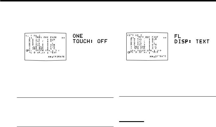
8 Memorizing the Volume Level for Each Source |
9 Showing the Text Information on the Display |
||||||||||||||||||||
—ONE TOUCH OPR (ONE TOUCH) |
—FL DISPLAY (DISP) |
|
|
|
|||||||||||||||||
|
[On-screen display] |
|
[Front panel] |
|
[On-screen display] |
|
[Front panel] |
||||||||||||||
|
|
|
|
|
|
|
|
|
|
|
|
|
|
|
|
|
|
|
|
|
|
|
|
|
|
|
|
|
|
|
|
|
|
|
|
|
|
|
|
|
|
|
|
|
|
|
|
|
|
|
|
|
|
|
|
|
|
|
|
|
|
|
|
|
|
|
|
|
|
|
|
|
|
|
|
|
|
|
|
|
|
|
|
|
|
|
|
|
|
|
|
|
|
|
|
|
|
|
|
|
|
|
|
|
|
|
|
|
|
|
|
|
|
|
|
|
|
|
|
|
|
|
|
|
|
|
|
|
|
|
|
|
|
|
|
|
|
|
|
|
|
|
|
|
|
|
|
|
|
|
|
|
|
|
|
|
|
|
|
|
|
|
|
|
|
|
|
|
|
|
|
|
|
|
|
|
|
|
|
|
|
|
|
|
|
|
|
|
|
|
|
|
|
|
|
|
|
|
|
|
|
|
|
|
|
|
|
|
|
|
|
|
|
|
|
|
|
|
|
|
|
|
|
|
|
|
|
|
|
|
|
|
|
|
|
|
|
|
|
|
|
|
|
|
|
|
|
|
|
|
|
|
|
|
|
|
|
|
|
|
|
|
|
|
|
|
|
|
|
|
|
|
|
|
|
|
|
|
|
|
|
|
|
|
|
|
|
|
|
|
|
|
|
|
|
|
|
|
|
|
|
|
|
|
|
|
|
This unit memorizes some settings separately for each source—One Touch Operation (see page 20).
In addition, you can store the volume level for each source with the other memorized settings.
Select one of the following:
ON |
: Select this to store the volume level separately for each |
|
source. (The ONE TOUCH OPERATION indicator |
|
lights up on the display.) |
This receiver memorizes the volume level—
•when you change the source and
•when you change the source name.
OFF |
: Select this not to store the volume level. |
To recall the volume level
With the ONE TOUCH OPERATION indicator lit, the volume level for the currently selected source is recalled when the source is selected.
To cancel the One Touch Operation
Set One Touch Operation to “OFF” so that the ONE TOUCH OPERATION indicator goes off.
When you have connected an MD recorder or CD player equipped with TEXT COMPU LINK remote control system (see page 44), you can show the text information such as disc title or track title on the display of this receiver.
Select one of the following:
NORMAL |
: Source name and Surround/DSP mode appear |
(NORM) |
during play. |
|
|
TEXT |
: Text information appears during play. |
|
|
Note:
Though you have selected “TEXT,” the source name and Surround/DSP mode will appear while playing a disc that has no text information.
26
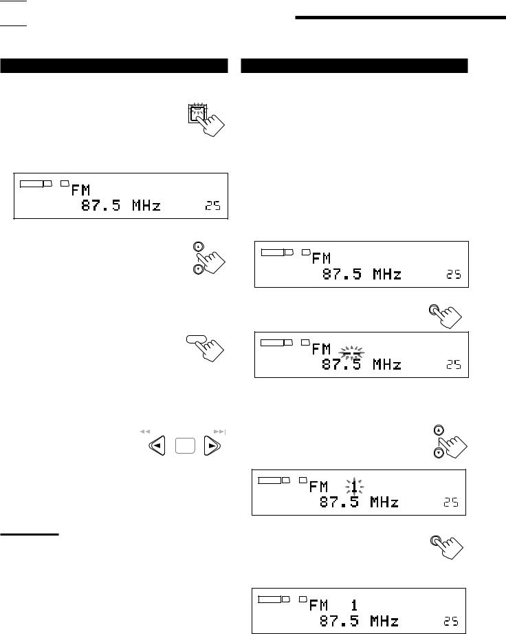

 Receiving Radio Broadcasts
You can browse through all the stations or use the preset function to go immediately to a particular station.
Tuning into Stations Manually |
Using Preset Tuning |
On the front panel:
1. Press FM/AM to select the band |
FM/AM |
(FM or AM). |
|
The FM/AM lamp on the front panel button lights up. The last received station of the selected band is tuned in.
•Each time you press the button, the band alternates between FM and AM.
ANALOG |
L |
R |
TUNED |
STEREO |
|
SPEAKERS 1 |
|
VOLUME |
|
2.Press FM/AM TUNING 5 or ∞ until you find the frequency you want.
•Pressing FM/AM TUNING 5 increases the frequency.
•Pressing FM/AM TUNING ∞ decreases the frequency.
From the remote control:
1. Press FM/AM to select the band (FM or AM).
The FM/AM lamp on the front panel button lights up. The last received station of the selected band is tuned in.
•Each time you press the button, the band alternates between FM and AM.
FM/AM TUNING
FM / AM
2. Press TUNING UP 3 or |
|
/REW |
|
|
|
PAUSE FF/ |
|
|
|
|
|||
|
|
|||||
|
|
|
|
|||
TUNING DOWN 2 until |
|
|
|
|
|
SET |
you find the frequency you |
|
DOWN – TUNING – UP |
||||
want. |
|
|||||
|
|
|
|
|
|
|
•Pressing TUNING UP 3 increases the frequency.
•Pressing TUNING DOWN 2 decreases the frequency.
Notes:
•When a station of sufficient signal strength is tuned in, the TUNED indicator lights up on the display.
•When an FM stereo program is received, the STEREO indicator also lights up.
•When you hold and then release the button in step 2, the frequency keeps changing until a station is tuned in.
Once a station is assigned to a channel number, the station can be quickly tuned in. You can preset up to 30 FM and 15 AM stations.
To store the preset stations
Before you start, remember...
There is a time limit in doing the following steps. If the setting is canceled before you finish, start from step 2 again.
On the front panel ONLY:
1.Tune in the station you want to preset (see “Tuning into Stations Manually” on the left).
•If you want to store the FM reception mode for this station, select the FM reception mode you want. See “Selecting the FM Reception Mode” on page 28.
ANALOG |
L |
R |
TUNED STEREO |
|
|||
|
SPEAKERS 1 |
VOLUME |
|
2. Press MEMORY. |
MEMORY |
||
ANALOG |
L |
R |
TUNED STEREO |
|
|||
|
SPEAKERS 1 |
VOLUME |
|
The channel number position starts flashing on the display for about 10 seconds.
3. Press FM/AM PRESET 5 or ∞ to |
FM/AM PRESET |
|
|
select a channel number while the |
|
channel number position is |
|
flashing. |
|
ANALOG L R |
TUNED STEREO |
|
|
SPEAKERS 1 |
VOLUME |
4. Press MEMORY again while the |
MEMORY |
selected channel number is |
|
flashing on the display. |
|
The selected channel number stops flashing.
The station is assigned to the selected channel number.
ANALOG |
L |
R |
TUNED |
STEREO |
|
|
|||
|
SPEAKERS 1 |
|
VOLUME |
|
5.Repeat steps 1 to 4 until you store all the stations you want.
To erase a stored preset station
Storing a new station on a used number erases the previously stored one.
27
 Loading...