


 Loading...
AUDIO/VIDEO CONTROL RECEIVER
RX-8030VBK RX-7030VBK/RX-7032VSL
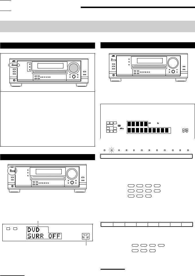
(For RX-8030VBK)
(For RX-8030VBK)
A/V CONTROL RECEIVER
1 2 3
MENU
4 5 6
ENTER
7/P 8 9
10/0 |
0 |
+10 |
CONTROL
INSTRUCTIONS
For Customer Use:
Enter below the Model No. and Serial No. which are located either on the rear, bottom or side of the cabinet. Retain this information for future reference.
Model No.
Serial No.
LVT1007-001A[J]
Warnings, Cautions and Others/
Mises en garde, précautions et indications diverses
|
|
CAUTION |
|
|
|
|
|
|
|
RISK OF ELECTRIC SHOCK |
|
|
|
DO NOT OPEN |
|
|
|
|
|
|
|
|
|
CAUTION: |
TO REDUCE THE RISK OF ELECTRIC SHOCK. |
||
|
DO NOT REMOVE COVER (OR BACK) |
||
|
NO USER SERVICEABLE PARTS INSIDE. |
||
REFER SERVICING TO QUALIFIED SERVICE PERSONNEL.
The lightning flash with arrowhead symbol, within an equilateral triangle is intended to alert the user to the presence of uninsulated "dangerous voltage" within the product’s enclosure that may be of sufficient magnitude to constitute a risk of electric shock to persons.
The exclamation point within an equilateral triangle is intended to alert the user to the presence of important operating and maintenance (servicing) instructions in the literature accompanying the appliance.
For U.S.A
This equipment has been tested and found to comply with the limits for a Class B digital device, pursuant to part 15 of the FCC Rules. These limits are designed to provide reasonable protection against harmful interference in a residential installation.
This equipment generates, uses and can radiate radio frequency energy and, if not installed and used in accordance with the instructions, may cause harmful interference to radio communications. However, there is no guarantee that interference will not occur in a particular installation. If this equipment does cause harmful interference to radio or television reception, which can be determined by turning the equipment off and on, the user is encouraged to try to correct the interference by one or more of the following measures:
Reorient or relocate the receiving antenna.
Increase the separation between the equipment and receiver. Connect the equipment into an outlet on a circuit different from that to which the receiver is connected.
Consult the dealer or an experienced radio/TV technician for help.
Changes or modifications not expressly approved by the manufacturer for compliance could void the user s authority to opratethe equipment.
WARNING: TO REDUCE THE RISK OF FIRE OR ELECTRIC SHOCK, DO NOT EXPOSE THIS APPLIANCE TO RAIN OR MOISTURE.
CAUTION
To reduce the risk of electrical shocks, fire, etc.:
1.Do not remove screws, covers or cabinet.
2.Do not expose this appliance to rain or moisture.
ATTENTION
Afin d’éviter tout risque d’électrocution, d’incendie, etc.:
1.Ne pas enlever les vis ni les panneaux et ne pas ouvrir le coffret de l’appareil.
2.Ne pas exposer l’appareil à la pluie ni à l’humidité.
Caution ––  STANDBY/ON button!
Disconnect the mains plug to shut the power off completely. The
 STANDBY/ON button in any position does not disconnect the mains line. The power can be remote controlled.
Attention –– Commutateur  STANDBY/ON!
Déconnecter la fiche de secteur pour couper complètement le courant. Le commutateur  STANDBY/ON ne coupe jamais complètement la ligne de secteur, quelle que soit sa position. Le courant peut être télécommandé.
Note to CATV system installer:
This reminder is provided to call the CATV system installer’s attention to Section 820-40 of the NEC which provides guidelines for proper grounding and, in particular, specifies that the cable ground shall be connected to the grounding system of the building, as close to the point of cable entry as practical.
For Canada/pour Le Canada
CAUTION: TO PREVENT ELECTRIC SHOCK, MATCH WIDE BLADE OF PLUG TO WIDE SLOT, FULLY INSERT
ATTENTION: POUR EVITER LES CHOCS ELECTRIQUES, INTRODUIRE LA LAME LA PLUS LARGE DE LA FICHE DANS LA BORNE CORRESPONDANTE DE LA PRISE ET POUSSER JUSQUAU FOND
THIS DIGITAL APPARATUS DOES NOT EXCEED THE CLASS B
LIMITS FOR RADIO NOISE EMISSIONS FROM DIGITAL APPA-
RATUS AS SET OUT IN THE INTERFERENCE-CAUSING EQUIPMENT STANDARD ENTITLED “DIGITAL APPARATUS,”
ICES-003 OF THE DEPARTMENT OF COMMUNICATIONS.
CET APPAREIL NUMERIQUE RESPECTE LES LIMITES DE BRUITS RADIOELECTRIQUES APPLICABLES AUX APPAREILS
NUMERIQUES DE CLASSE B PRESCRITES DANS LA NORME
SUR LE MATERIEL BROUILLEUR; “APPAREILS NUMERIQUES”, NMB-003 EDICTEE PAR LE MINISTRE DES COMMUNICATIONS.
G-1

Table of Contents |
|
Introduction ................................................ |
2 |
Features ...................................................................................... |
2 |
Precautions ................................................................................. |
2 |
Parts Identification ...................................... |
3 |
Remote Control .......................................................................... |
3 |
Front Panel ................................................................................. |
4 |
Rear Panel .................................................................................. |
6 |
Getting Started........................................... |
8 |
Before Installation ...................................................................... |
8 |
Checking the Supplied Accessories ........................................... |
8 |
Putting Batteries in the Remote Control .................................... |
8 |
Connecting the FM and AM Antennas ....................................... |
8 |
Connecting the Speakers ............................................................ |
9 |
Connecting Audio/Video Components ..................................... |
11 |
7Analog Connections ............................................................. |
11 |
7 Digital Connections .............................................................. |
16 |
Connecting the Power Cord ..................................................... |
16 |
Basic Operations ....................................... |
17 |
Daily Operational Procedure .................................................... |
17 |
Turning On the Power .............................................................. |
17 |
Selecting the Source to Play ..................................................... |
17 |
Adjusting the Volume ............................................................... |
18 |
Selecting the Front Speakers .................................................... |
19 |
Activating and Adjusting the Subwoofer Sound ...................... |
19 |
Selecting the Analog or Digital Input Mode ............................ |
19 |
Setting the Dynamic Range ...................................................... |
20 |
Attenuating the Input Signal .................................................... |
20 |
Turning Analog Direct On and Off .......................................... |
21 |
Making Sounds Natural ............................................................ |
21 |
Changing the Source Name ...................................................... |
21 |
Reinforcing the Bass ................................................................ |
22 |
Muting the Sound ..................................................................... |
22 |
Changing the Display Brightness ............................................. |
22 |
Using the Sleep Timer .............................................................. |
22 |
Receiving Radio Broadcasts ........................ |
23 |
Tuning in to Stations Manually ................................................ |
23 |
Using Preset Tuning ................................................................. |
23 |
Selecting the FM Reception Mode ........................................... |
24 |
Basic Settings........................................... |
25 |
Setting the Speakers Configuration .......................................... |
25 |
Basic Setting Items ................................................................... |
26 |
Basic Procedure ........................................................................ |
27 |
Setting the Speakers ........................................................... |
27 |
Setting the Speaker Distance ............................................. |
28 |
Setting the Bass Sounds ..................................................... |
28 |
Selecting main or sub channel—DUAL MONO ............... |
29 |
Setting the Digital Input Terminals .................................... |
29 |
Setting the Component Video Input ................................... |
30 |
Memorizing the Volume Level for Each Source ................ |
30 |
Adjusting Sound ........................................ |
31 |
Basic Setting Items ................................................................... |
31 |
Basic Procedure ........................................................................ |
31 |
Adjusting the Equalization Patterns ................................... |
32 |
Adjusting the Speaker Output Levels ................................ |
32 |
Adjusting the Sound Parameters for the |
|
Surround and DSP modes ............................................ |
33 |
Using the Surround Modes .......................... |
34 |
Reproducing Theater Ambience ................................................ |
34 |
Introducing the Surround Modes ............................................. |
34 |
Surround Modes Applicable to the Various Software .............. |
36 |
Activating the Surround Modes ............................................... |
37 |
7Activating the EX/ES setting ................................................ |
37 |
7Activating the Surroung modes ............................................ |
37 |
Using the DSP Modes ................................ |
38 |
Reproducing the Sound Field ................................................... |
38 |
Introducing the DSP Modes ..................................................... |
38 |
Activating the DSP Modes ....................................................... |
39 |
Using the DVD MULTI Playback Mode .......... |
40 |
Activating the DVD MULTI Playback Mode .......................... |
40 |
COMPU LINK Remote Control System ......... |
41 |
AV COMPU LINK Remote Control System .... |
42 |
Operating JVC’s Audio/Video Components ... |
44 |
Operating Audio Components .................................................. |
44 |
Operating Video Components .................................................. |
46 |
Operating Other Manufacturers’ Video |
|
Equipment ............................................ |
47 |
Troubleshooting ......................................... |
50 |
Specifications............................................ |
51 |

 Remote
NOT
This mark indicates that ONLY the remote control CAN be used for the operation explained.
This mark indicates that the remote control CANNOT be used for the operation explained. Use the buttons on the front panel.
RX-8030V
ONLY
RX-7030V RX-7032V
ONLY
Features with this mark are provided only for RX-8030VBK.
Features with this mark are provided only for RX-7030VBK/RX-7032VSL.
1


 Introduction
We would like to thank you for purchasing one of our JVC products.
Before operating this unit, read this manual carefully and thoroughly to obtain the best possible performance from your unit, and retain this manual for future reference.
Features
CC (Compensative Compression) converter
—ONLY for RX-8030VBK
CC Converter eliminates jitter and ripples, achieving a drastic reduction in digital distortion by processing the digital music data in 24 bit–quantization and by expanding the sampling frequency to 128 kHz (for fs 32 kHz signals)/176.4 kHz (for fs 44.1 kHz signals)/192 kHz (for fs 48 kHz signals). By using the CC Converter, you can obtain a natural sound field from any source. (See page 21 for details.)
K2 technology—ONLY for RX-8030VBK
K2 technology has been designed to enable natural audio reproduction, achieving a drastic reduction in digital distortion and creating original sound ambience with high precision.
Compatible with various audio formats including DTS 96/24
RX-8030VBK and RX-7030VBK/RX-7032VSL allow you to enjoy a newly introduced audio format such as Dolby Digital EX, Dolby Pro Logic II, DTS-ES, DTS Neo:6, and DTS 96/24.
•This unit is also compatible with Dual Mono signals recorded in Dolby Digital and DTS discs.
DAP (Digital Acoustic Processor)
Sound field simulation technology allows precise ambience recreation of existing theaters and halls. Thanks to the highperformance DSP (Digital Signal Processor) and high-capacity memory, you can enjoy multi-channel surround sound by playing 2-channel or multi-channel software according to the speaker setting.
Multi-channel headphone virtual surround sound—3D HEADPHONE Mode
Precautions
Power sources
•When unplugging the receiver from the wall outlet, always pull the plug, not the AC power cord.
•Do not handle the AC power cord with wet hands.
•If you are not going to operate the receiver for an extended period of time, unplug the AC power cord from the wall outlet.
Ventilation
High power amplifiers built in this receiver will generate heat inside the cabinet. For safety, observe the following carefully.
•Make sure there is good ventilation around the receiver. Poor ventilation could overheat and damage the receiver.
•Do not block the ventilation openings or holes. (If the ventilation openings or holes are blocked by a newspaper or cloth, etc., the heat may not be able to get out.)
Others
•Should any metallic object or liquid fall onto the unit, unplug the unit and consult your dealer before operating any further.
•Do not expose this apparatus to rain, moisture, dripping or splashing and that no objects filled with liquids, such as vases shall be placed on the apparatus.
•Do not disassemble the unit since there are no user serviceable parts inside.
If anything goes wrong, unplug the AC power cord and consult your JVC dealer.
The built-in headphone virtual surround system is compatible with Multi-channel software like Dolby Digital, DTS Surround, etc. Thanks to the new signal processing algorithms used by the highperformance DSP, you can enjoy a natural surround sound through the headphones.
COMPU LINK/AV COMPU LINK remote control systems
These COMPU LINK remote control systems allow you to operate other JVC’s audio/video components from this receiver.
2

 Parts Identification
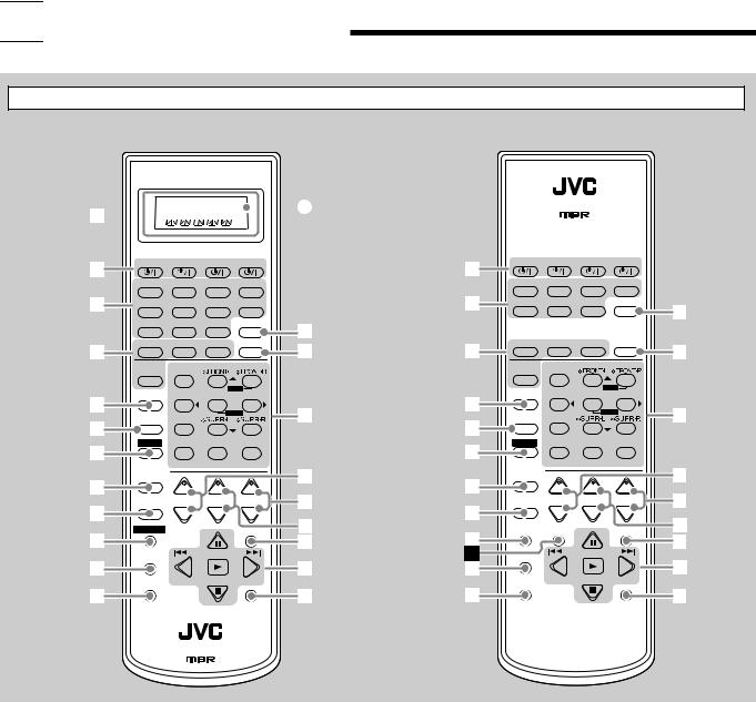
Remote Control
RX-8030VBK |
RX-7030VBK/RX-7032VSL |
A/V CONTROL RECEIVER
1


 A
A
2 |
CATV/DBS |
VCR 1 |
TV |
AUDIO |
|
2 |
CATV/DBS |
VCR |
TV |
AUDIO |
|
|
|
|
|
|
|
|
|
|
|
||
|
DVD MULTI |
DVD |
CD |
FM/AM |
|
|
DVD MULTI |
DVD |
CD |
FM/AM |
|
3 |
VCR 1 |
VCR 2 |
CDR |
TAPE/MD |
|
3 |
TV/DBS |
VCR |
TAPE/CDR ANALOG/DIGITAL |
e |
|
|
|
|
|
|
|
|
|
|
|
INPUT |
|
|
|
|
|
|
|
|
|
|
|
|
|
|
TV/DBS |
VIDEO |
PHONO ANALOG/DIGITAL |
e |
|
|
|
|
|
|
|
|
|
|
|
INPUT |
|
|
|
|
|
|
|
4 |
SURROUND |
DSP |
SURR/DSP |
ANALOG |
r |
4 |
SURROUND |
DSP |
SURR/DSP |
ANALOG |
r |
|
|
OFF |
DIRECT |
|
|
OFF |
DIRECT |
||||
|
EX/ES |
BASS BOOST |
|
|
|
EX/ES |
BASS BOOST |
|
|
||
|
|
1 |
2 |
3 |
|
|
|
1 |
2 |
3 |
|
|
|
|
MENU |
|
|
|
|
MENU |
|
||
5 |
CCCONVERTER TEST CENTER SUBWOOFER |
|
5 |
CDDISC |
TEST CENTER SUBWOOFER |
|
|||||
|
4 |
5 |
6 |
t |
|
4 |
5 |
6 |
t |
||
|
MIDNIGHT |
|
ENTER |
|
MIDNIGHT |
|
ENTER |
||||
6 |
|
|
|
6 |
|
8 |
9 |
||||
MODE |
7/P |
8 |
9 |
|
MODE |
7/P |
|
||||
7 |
SOUND |
DIGITALEQ SURR BACK |
|
7 |
SOUND |
DIGITALEQ SURR BACK |
|
||||
|
10/0 |
0 |
+10 |
|
|
10/0 |
0 |
+10 |
|
||
|
|
RETURN |
FMMODE |
100+ |
|
|
CATV/DBS |
RETURN |
FMMODE |
100+ |
|
|
CATV/DBS |
|
|
|
y |
|
|
|
|
y |
|
8 |
CONTROL |
+ |
+ |
+ |
8 |
CONTROL |
+ |
+ |
+ |
||
9 |
TV/VIDEO CH/ LEVEL |
TV |
|
u |
9 |
TV/VIDEO |
CH/ LEVEL |
TV |
VOLUME |
u |
|
|
|
− |
|
i |
|
|
− |
|
i |
||
|
CONTROL |
|
|
|
|
VCR |
TAPE/CDR |
|
MUTING |
||
|
|
|
MUTING |
p |
CONTROL CONTROL |
|
|||||
p |
|
|
|
o |
|
o |
|||||
|
|
|
|
|
|
|
|
||||
|
REC PAUSE |
/REW |
FF/ |
|
s |
REC PAUSE |
/REW |
FF/ |
|
||
q |
|
|
|
; |
q |
|
|
|
; |
||
|
|
|
|
|
|
|
|
||||
DOWN — TUNING — UP |
|
|
DOWN — TUNING — UP |
SLEEP |
|
w |
SLEEP |
w |
a |
a |
|
DIMMER |
|
|
DIMMER |
A/V CONTROL RECEIVER
1Only for RX-8030VBK: Display window
•When the remote operation mode changes, it is shown on this display.
•Signal transmission indicator (A) lights up when
transmitting signals.
2 buttons (17, 46 – 48)
•For RX-8030VBK:
CATV/DBS  , VCR 1
  , TV
, TV  , AUDIO
•For RX-7030VBK/RX-7032VSL:
CATV/DBS  , VCR
, VCR  , TV
, TV  , AUDIO
3Source selection buttons (17, 18, 19, 23, 24, 37, 40)
•For RX-8030VBK:
DVD MULTI, DVD, CD*, FM/AM*, VCR 1, VCR 2, CDR*, TAPE/MD*, TV/DBS, VIDEO, PHONO*
•For RX-7030VBK/RX-7032VSL:
DVD MULTI, DVD, CD*, FM/AM*, TV/DBS, VCR,
TAPE/CDR*
*When you press one on these source selection buttons on the remote control, the receiver automatically turns on.
4• SURROUND button (37)
•DSP button (39)
•SURR (surround)/DSP OFF button (37, 39)
•EX/ES button (37)
5• For RX-8030VBK: CC CONVERTER button (21)
•For RX-7030VBK/RX-7032VSL: CD DISC button (45)
6 MIDNIGHT MODE button (20)
7 SOUND button (22, 32, 33)
8 CATV/DBS CONTROL button (47)
9 TV/VIDEO button (46, 47)
p• For RX-8030VBK: CONTROL button (44 – 46)
• For RX-7030VBK/RX-7032VSL:
VCR CONTROL button (46) q REC PAUSE button (45, 46, 48) w SLEEP button (22)
e ANALOG/DIGITAL INPUT button (20) r ANALOG DIRECT button (21)
t• 10 keys for operating the tuner (24)
•10 keys for adjusting sound (32, 33)
•10 keys for operating audio/video components (44 – 48)
y• CH (channel) +/– buttons (46 – 48)
•*LEVEL +/– buttons (32, 33, 44)
The LEVEL +/– buttons function only after pressing SOUND then 10 keys which are marked with an asterisk (*) on the
remote control.
u VOLUME +/– buttons (18)
i TV VOL (volume) +/– buttons (46, 47) o MUTING button (22)
;• TUNING UP/DOWN buttons (23)
• Operating buttons for audio/video components (44 – 46, 48)
3, 8, 7, 4/REW, FF/¢ a DIMMER button (22)
åOnly for RX-7030VBK/RX-7032VSL:
TAPE/CDR CONTROL button (45)
3
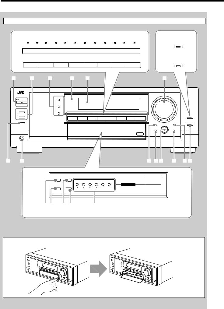
Front Panel
6 RX-8030VBK |
|
|
|
|
|
|
|
|
|
|
|
|
|
8 RX-8030VBK |
||||||||
|
|
|
|
|
|
|
|
|
|
|
|
|
|
|
|
|
|
|
|
|
|
CC CONVERTER |
DVD MULTI |
|
DVD |
|
VCR 1 |
|
VCR 2 |
|
VIDEO |
|
TV SOUND |
|
PHONO |
|
CD |
|
CDR |
|
TAPE/MD |
|
FM |
|
AM |
|
|
|
|
|
|
|
|
|
|
|
||||||||||||
|
|
|
|
|
/DBS |
|
|
|
|
|
|
|||||||||||
|
|
|
|
|
|
|
|
|
|
|
|
|
|
|
|
|
|
|
|
|
RX-7030VBK |
|
|
|
|
|
|
|
|
|
|
|
|
|
|
|
|
|
|
|
|
|
|
|
|
RX-7030VBK/RX-7032VSL |
|
|
|
|
|
|
|
|
|
|
|
|
|
RX-7032VSL |
||||||||
BASS BOOST
DVD MULTI |
DVD |
VCR |
TV SOUND/DBS |
|
CD |
TAPE/CDR |
|
FM |
AM |
|
|
2 |
|
|
DVD MULTI |
DVD |
VCR |
TV SOUND/DBS |
CD |
TAPE/CDR |
FM |
AM |
|
|
|
|
|
||||||||
SUBWOOFER OUT ON/OFF |
|
|
|
|
|
|
|
|
|
|
|
|
|
|
|
|
|
|
|
|
|
|
ANALOG DIRECT |
|
|
|
|
|
|
|
|
|
|
|
MULTI JOG |
|
|
|
|
|
|
|
|
|
|
QUICK SPEAKER |
|
|
|
|
|
|
|
|
|
|
|
SETUP |
EXIT |
|
|
|
|
|
|
|
|
|
|
PUSH – OPEN |
|
PHONES |
|
|
|
|
|
|
|
|
|
|
|
9
MIDNIGHT
/ ES |
|
|
|
FM/AM TUNING |
FM/AM PRESET FM MODE MEMORY |
INPUT |
INPUT |
TUNER CONTROL |
|
DIGITAL |
|
INPUT ATT
q w e r |
t |
y |
|
|
|
|
Inside the front door |
|
How to open the front door
Press down on PUSH OPEN.
4
Front Panel
1  STANDBY/ON button and STANDBY lamp (17)
2• SPEAKERS ON/OFF 1 button (19)
•SPEAKERS ON/OFF 2 button (19) 3 • SURROUND button (37)
•DSP button (39)
•SURROUND/DSP OFF button (37, 39) 4 Remote sensor
5 Display window (17)
6 • For RX-8030VBK: Source selection buttons and lamps (17, 18, 19, 21, 23, 24, 37, 40)
DVD MULTI, DVD, VCR 1, VCR 2, VIDEO,
TV SOUND/DBS, PHONO, CD, CDR, TAPE/MD, FM, AM (The lamp above the button for selected source lights up.)
•For RX-7030VBK/RX-7032VSL: Source selection buttons (17, 18, 19, 21, 23, 24, 37, 40)
DVD MULTI, DVD, VCR , TV SOUND/DBS, CD,
TAPE/CDR, FM, AM
7 MASTER VOLUME control (18)
8• For RX-8030VBK: CC CONVERTER button and lamp (21)
•For RX-7030VBK/RX-7032VSL: BASS BOOST button and lamp (22)
9 SUBWOOFER OUT ON/OFF button (19) p PHONES jack (19)
q EX/ES button (37)
w • INPUT ANALOG button (20)
• INPUT ATT button (20)
e MIDNIGHT MODE button (20) r INPUT DIGITAL button (20)
tTUNER CONTROL buttons
•FM/AM TUNING 5 / ∞ buttons (23)
•FM/AM PRESET 5 / ∞ buttons (23, 24)
•FM MODE button (24)
•MEMORY button (23)
y Only for RX-8030VBK: VIDEO input jacks (13) DIGITAL optical terminal, S-VIDEO jack, VIDEO jack, AUDIO—L/R jacks
u SETTING button (27)
i QUICK SPEAKER SETUP button (25)
o• MULTI JOG control (25, 27, 31)
•PUSH SET button (25, 27, 31) ; EXIT button (27, 31)
a ADJUST button (31)
s ANALOG DIRECT button and lamp (21)
Display Window
1 2 3 4 5 |
67 8 9 0 - = ~ ! @ |
||||||||
DUAL |
ANALOG DIGITAL AUTO 96/24 |
MULTI |
TUNED STEREO |
AUTO MUTING |
ONETOUCH OPERATION SLEEP |
||||
L |
C |
R |
LINEAR PCM |
|
PRO LOGIC |
NEO:6 VIRTUAL |
MIDNIGHT MODE DIGITAL |
||
SUBWFR |
LFE |
DIGITAL |
|
DSP 3D - PHONIC |
HEADPHONE |
SPEAKERS |
2 BASS BOOST |
||
LS |
S |
RS |
|
|
|
|
INPUT ATT |
|
SB |
|
|
|
|
|
|
|
|
|
|
|
|
VOLUME |
|
|
|
|
|
|
|
|
|
|
# |
$ |
% |
^ |
& |
* ( ) |
_ + |
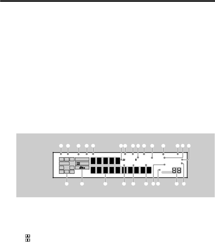
Display Window
1 DUAL indicator (35)
2 ANALOG indicator (20)
3 DIGITAL AUTO indicator (20)
4 96/24 indicator (35)
5 MULTI indicator (40)
6• PRO LOGIC indicator (34)
•PRO LOGIC II indicator (35) 7 TUNED indicator (23)
8 STEREO indicator (23, 24)
9 NEO:6 indicator (35)
0 AUTO MUTING indicator (24)
- VIRTUAL SB (Surround Back) indicator (34, 35) = ONE TOUCH OPERATION indicator (30)
~ SLEEP indicator (22)
! MIDNIGHT MODE indicator (20)
@ DIGITAL EQ (equalization) indicator (32)
# Speaker and signal indicators (18) $ Digital signal format indicators (20) % Main Display (17)
^ DSP indicator (19, 38)
& 3D-PHONIC indicator (38)
* HEADPHONE indicator (19, 38) ( SPEAKERS 1/2 indicators (19)
) INPUT ATT (attenuator) indicator (20) _ VOLUME level indicator (17, 22)
+ BASS BOOST indicator (22)
5

Rear Panel
RX-8030VBK |
|
|
|
|
|
|
|
|
|
|
|
|
|
|
|
1 |
|
|
2 |
3 |
|
|
4 |
|
5 |
|
6 |
|
7 |
8 |
9 |
DIGITAL IN |
|
|
|
AUDIO |
VIDEO |
|
|
PREOUT |
|
|
|
COMPU LINK-4 |
AV |
|
|
SUBWOOFER |
CENTER |
|
LEFT |
S-VIDEO |
|
|
FRONT |
COMPONENT VIDEO |
|
||||||
|
|
|
SURR BACK |
SURR |
CENTER |
|
|||||||||
|
|
|
(SYNCHRO) |
COMPULINK- |
|
||||||||||
|
|
|
|
DVD |
|
|
L |
|
|
L |
DVD |
|
|
|
|
|
|
|
|
IN |
|
|
|
|
IN |
|
|
|
|
||
|
DVD |
|
|
FRONT |
|
|
ANTENNA |
|
|
|
|
|
|
|
|
|
|
|
|
|
|
|
|
|
|
|
|
|
|||
|
IN |
|
|
|
|
|
|
|
|
|
|
|
|
|
|
|
SURR |
|
|
TV SOUND |
|
AM |
R |
|
|
R |
DBS |
|
|
|
|
DIGITAL 1 (DVD) |
|
|
DBS |
|
|
|
|
|
IN |
|
|
|
|
||
(REAR) |
|
|
|
EXT |
|
|
|
|
|
|
|
|
|||
|
|
|
|
IN |
|
|
AM |
|
SUBWOOFER |
|
|
|
|
|
|
|
|
|
|
|
|
|
LOOP |
|
|
|
|
|
|
|
|
|
OUT |
|
|
|
|
|
|
|
|
|
|
|
|
|
|
|
|
|
OUT |
|
|
|
|
|
MONITOR |
|
|
|
|
||
|
(REC) |
|
|
|
|
|
|
|
|
|
|
|
|||
DIGITAL 2 (CD) |
TAPE |
|
|
(REC) |
|
|
|
|
|
|
OUT |
|
|
|
|
|
|
|
VCR 1 |
|
|
|
|
|
|
|
PB |
PR |
|
|
|
|
MD |
|
|
|
|
|
|
|
|
Y |
|
|
|||
IN |
IN |
|
(PLAY) |
(PLAY) |
|
DIGITAL 3 (TV) |
|
|
OUT |
OUT |
|
(REC) |
||
(REC) |
||
DIGITAL 4 (CDR) |
VCR 2 |
|
CDR |
||
IN |
IN |
|
(PLAY) |
(PLAY) |
|
|
PCM/ DOLBY DIGITAL |
|
MONITOR |
/ DTS |
|
|
|
|
OUT |
DIGITAL OUT |
PHONO |
CD |
|
IN |
IN |
|
RIGHT |
LEFT |
|
CAUTION : SPEAKER IMPEDANCE 8 |
16 |
|
|
|
|
|
|
|
|
||
|
|
|
|
|
|
|
|
CAUTION : SPEAKER IMPEDANCE |
||||
FM 75 |
+ |
|
|
|
|
|
|
+ 1 |
OR |
2 |
: 8 |
16 |
COAXIAL |
|
|
|
|
|
|
|
1 |
|
2 |
: 16 |
|
|
|
|
|
|
|
|
|
AND |
32 |
|||
SINGLE USE |
|
|
|
|
|
|
|
|
|
|
|
|
See Instruction |
|
|
|
|
|
|
|
|
|
|
|
|
Manual For |
|
|
|
|
|
|
|
|
|
|
|
|
Connection |
|
|
|
|
|
|
|
|
|
|
|
|
|
– |
|
|
|
|
|
|
– |
|
|
|
|
|
RIGHT |
LEFT |
RIGHT |
LEFT |
RIGHT |
LEFT |
RIGHT |
LEFT |
|
|
|
|
SURROUND |
SPEAKERS |
SURROUND SPEAKERS |
CENTER |
FRONT SPEAKERS |
|
|
|
|
|
|
|
|
|
|
|
|
|
|
|
|
|
|
|
|
|
|
|
|
|
|
|
|
|
|
|
|
|
|
|
|
|
|
|
|
|
|
|
|
|
|
|
|
|
|
|
|
|
|
|
|
|
|
|
|
|
|
|
|
|
|
|
|
|
p |
|
|
y |
|
|
|
q |
|
w |
|
e |
|
r |
|
t |
|
|
|
||||
RX-7030VBK/RX-7032VSL
1 |
2 |
3 |
4 5 |
6 |
7 |
8 |
9 |
DIGITAL IN |
AUDIO |
VIDEO |
SUBWOOFER |
|
COMPU LINK-4 |
AV |
|
|
S-VIDEO |
COMPONENT VIDEO |
|||||
SUBWOOFER CENTER |
LEFT |
OUT |
|||||
(SYNCHRO) |
COMPULINK- |
||||||
|
|
|
|
|
|
|
DVD |
|
|
DVD |
|
|
|
|
|
|
|
|
IN |
ANTENNA |
|
IN |
|
|
|
|
|
|
|
DVD |
FRONT |
|
|
|
|
|
|
|
|
|
|
IN |
|
|
|
|
|
|
|
|
|
|
|
SURR |
TV SOUND |
AM |
|
DBS |
|
|
|
|
|
|
DIGITAL 1 (DVD) |
|
IN |
|
|
|
|
|
|
|||
(REAR) |
DBS |
EXT |
|
|
|
|
|
|
|
||
|
|
IN |
|
AM |
|
|
|
|
|
|
|
|
RIGHT |
LEFT |
|
LOOP |
|
|
|
|
|
|
|
|
|
OUT |
|
|
MONITOR |
|
|
|
|
|
|
DIGITAL 2 (CD) |
|
(REC) |
|
|
OUT |
|
|
|
|
|
|
|
|
VCR |
|
|
Y |
PB |
PR |
|
|
|
|
|
|
IN |
|
CAUTION : SPEAKER IMPEDANCE 8 |
16 |
|
|
|
|
|
|
DIGITAL 3 (TV) |
|
(PLAY) |
|
|
|
|
|
|
|
|
|
|
|
|
|
|
|
|
|
|
|
|
|
|
|
|
FM 75 |
+ |
|
|
+ |
|
CAUTION : SPEAKER IMPEDANCE |
||
|
|
OUT |
COAXIAL |
|
|
|
|
|
1 |
OR 2 : 8 |
16 |
|
|
|
|
|
|
|
|
||||
DIGITAL 4 (CDR) |
|
(REC) |
|
|
|
|
|
|
1 AND 2 : 16 |
|
|
|
TAPE |
SINGLE USE |
|
|
|
+ |
+ |
32 |
|||
|
|
|
|
|
|||||||
|
|
CDR |
|
|
|
|
|
|
|||
|
|
IN |
See Instruction |
|
|
|
|
|
|
|
|
|
|
Manual For |
|
|
|
|
|
|
|
|
|
|
|
(PLAY) |
|
|
|
– |
– |
|
|
|
|
|
|
|
Connection |
|
|
|
|
|
|
||
PCM/ DOLBY DIGITAL |
|
MONITOR |
|
– |
|
|
– |
|
|
|
|
/ DTS |
|
|
|
|
|
RIGHT |
LEFT |
|
|
|
|
|
|
OUT |
|
|
|
|
|
|
|
||
DIGITAL OUT |
CD |
RIGHT |
LEFT |
RIGHT |
LEFT |
RIGHT |
LEFT |
|
IN |
||||||||
|
|
|
|
|
|
|
|
|
|
CENTER |
1 |
2 |
SURROUND |
SPEAKERS |
SURROUND SPEAKERS |
SPEAKER |
|
FRONT SPEAKERS |
p |
q |
w |
e |
r |
t |
6

Rear Panel
RX-8030VBK
1DIGITAL IN terminals (16)
•Coaxial: DIGITAL 1 (DVD)
•Optical: DIGITAL 2 (CD), DIGITAL 3 (TV), DIGITAL 4 (CDR)
2AUDIO input/output jacks (11 – 15)
•Input: DVD IN—FRONT, CENTER, SUBWOOFER, SURR (REAR), TV SOUND/DBS IN,
VCR 1 IN (PLAY), VCR 2 IN (PLAY), CD IN, TAPE/MD IN (PLAY), CDR IN (PLAY), PHONO IN
•Output: VCR 1 OUT (REC), VCR 2 OUT (REC),
TAPE/MD OUT (REC), CDR OUT (REC)
3 S-VIDEO and composite VIDEO input/output jacks (14, 15)
• Input: DVD IN, TV SOUND/DBS IN, VCR1 IN (PLAY), VCR 2 IN (PLAY)
• Output: VCR 1 OUT (REC), VCR 2 OUT (REC), MONITOR OUT
4 FM/AM ANTENNA terminals (8)
5PREOUT jacks (10, 11)
•FRONT, CENTER, SUBWOOFER, SURR, SURR BACK 6 COMPONENT VIDEO input/output jacks (14, 15)
|
• Input: |
DVD IN, DBS IN |
|
• Output: |
MONITOR OUT |
7 |
COMPU LINK-4 (SYNCHRO) terminals (41) |
|
8 |
AV COMPULINK-III terminals (42) |
|
9 |
AC power cord (16) |
|
p DIGITAL OUT terminal (16)
q SURROUND BACK SPEAKERS terminals (10) w SURROUND SPEAKERS terminals (10)
e CENTER SPEAKER terminals (10) r FRONT SPEAKERS 1 terminals (10) t FRONT SPEAKERS 2 terminals (10) Ô Earth (ground) terminal (11)
RX-7030VBK/RX-7032VSL
1DIGITAL IN terminals (16)
•Coaxial: DIGITAL 1 (DVD)
•Optical: DIGITAL 2 (CD), DIGITAL 3 (TV), DIGITAL 4 (CDR)
2AUDIO input/output jacks (12 – 15)
•Input: DVD IN—FRONT, CENTER, SUBWOOFER, SURR (REAR), TV SOUND/DBS IN,
VCR IN (PLAY), TAPE/CDR IN (PLAY), CD IN
•Output: VCR OUT (REC), TAPE/CDR OUT (REC)
3 |
S-VIDEO and composite VIDEO input/output jacks (14, 15) |
|
|
• Input: |
DVD IN, TV SOUND/DBS IN, VCR IN (PLAY) |
|
• Output: |
VCR OUT (REC), MONITOR OUT |
4 |
FM/AM ANTENNA terminals (8) |
|
5 |
SUBWOOFER OUT jack (10) |
|
6 |
COMPONENT VIDEO input/output jacks (14, 15) |
|
|
• Input: |
DVD IN, DBS IN |
|
• Output: |
MONITOR OUT |
7 |
COMPU LINK-4 (SYNCHRO) terminals (41) |
|
8 |
AV COMPULINK-III terminals (42) |
|
9 |
AC power cord (16) |
|
p DIGITAL OUT terminal (16)
q SURROUND BACK SPEAKERS terminals (10) w SURROUND SPEAKERS terminals (10)
e CENTER SPEAKER terminals (10) r FRONT SPEAKERS 1 terminals (10) t FRONT SPEAKERS 2 terminals (10)
Differences between RX-8030VBK and RX-7030VBK/RX-7032VSL |
: Supplied : Not supplied |
|||||
|
|
|
|
|
|
|
|
|
|
Video jacks (input/output) |
PREOUT jacks |
CC Converter |
Selectable source |
|
|
|
|
|
|
|
|
RX-8030VBK |
Composite video (4/3) |
|
|
DVD MULTI, DVD, VCR 1, VCR 2, VIDEO, |
|
|
|
|
S-video (4/3) |
|
|
TV SOUND/DBS, PHONO, CD, CDR, TAPE/MD, |
|
|
|
Component video (2/1) |
|
|
FM, AM |
|
|
|
|
|
|
|
|
RX-7030VBK |
Composite video (3/2) |
|
|
DVD MULTI, DVD, VCR, |
|
|
RX-7032VSL |
S-video (3/2) |
|
|
TV SOUND/DBS, CD, TAPE/CDR, FM, AM |
|
|
|
|
Component video (2/1) |
|
|
|
|
|
|
|
|
||
Remote Control |
Display Window |
Color |
|
|
||
|
|
|
|
|
|
|
|
RM-SRX8030J |
|
Black |
|
|
|
|
|
|
|
|
|
|
|
RM-SRX7030J |
|
Black |
|
|
|
|
|
|
|
|
|
|
|
RM-SRX7032U |
|
Silver |
|
|
|
|
|
|
|
|
|
|
7

 Getting Started
This section explains how to connect audio/video components and speakers to the receiver, and how to connect the power supply.
Before Installation
General Precautions
•Be sure your hands are dry.
•Turn the power off to all components.
•Read the manuals supplied with the components you are going to connect.
If the remote control cannot transmit signals or operate the receiver correctly, replace the batteries. Use two R6P(SUM-3)/AA(15F) type dry-cell batteries.
Notes:
•Supplied batteries are for the initial setup. Replace for continued use.
•After replacing the batteries, set the manufacturers’ codes again
(see pages from 47 to 49).
Locations
•Install the receiver in a location that is level and protected from moisture.
•The temperature around the receiver must be between –5˚C and 35˚C (23˚F and 95˚F ).
•Make sure there is good ventilation around the receiver. Poor ventilation could cause overheating and damage the receiver.
Handling the receiver
•Do not insert any metal object into the receiver.
•Do not disassemble the receiver or remove screws, covers, or cabinet.
•Do not expose the receiver to rain or moisture.
Checking the Supplied Accessories
Check to be sure you have all of the following items, which are supplied with the receiver.
The number in the parentheses indicates quantity of the pieces supplied.
•Remote Control (1)
•Batteries (2)
•AM Loop Antenna (1)
•FM Antenna (1)
If anything is missing, contact your dealer immediately.
Putting Batteries in the Remote Control
Before using the remote control, insert the two supplied batteries
first. |
|
|
1 |
2 |
3 |
|
R6P(SUM-3)/ |
|
|
AA(15F) |
|
CAUTION:
Follow these precautions to avoid leaking or cracking cells:
•Place batteries in the remote control so they match the polarity:
(+) to (+) and (–) to (–).
•Use the correct type of batteries. Batteries that look similar may differ in voltage.
•Always replace both batteries at the same time.
•Do not expose batteries to heat or flame.
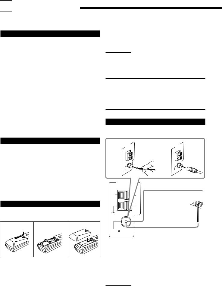
Connecting the FM and AM Antennas
FM Antenna Connections
ANTENNA |
ANTENNA |
A |
B |
75 |
75 |
FM |
FM |
COAXIAL |
COAXIAL |
FM Antenna (supplied)
Extend the supplied FM antenna horizontally.
FM 75 |
Outdoor FM Antenna Cable |
COAXIAL
(not supplied)
A.Using the Supplied FM Antenna
The FM antenna provided can be connected to the FM 75 Ω
COAXIAL terminal as temporary measure.
1.Press and slide the battery cover on the back of the remote control.
2.Insert the batteries.
• Make sure to match the polarity: (+) to (+) and (–) to (–).
3.Replace the cover.
B.Using the Standard Type Connector (Not Supplied)
A standard type connector should be connected to the FM 75 Ω COAXIAL terminal.
Note:
If reception is poor, connect the outdoor FM antenna (not supplied).
Before attaching a 75 Ω coaxial cable with a connector (the kind with a round wire going to an outdoor antenna), disconnect the supplied FM antenna.
8
AM Antenna Connections
Turn the loop until you have the best reception.
ANTENNA
AM
EXT
AM |
AM Loop Antenna |
LOOP |
(supplied) |
|
1 |
2 |
3 |
Basic connecting procedure
1 Twist and remove the insulation at the end of each speaker signal cable (not supplied).
2 Open the speaker terminal.
+ –
LEFT
RIGHT
RX-7030VBK/RX-7032VSL
(For FRONT SPEAKERS 2 terminals)
3 Insert the speaker signal cable.
+ –
LEFT
RIGHT
4 Close the speaker terminal.
Outdoor single vinyl-covered wire (not supplied)
Notes:
•If the AM loop antenna wire is covered with vinyl, remove the vinyl by twisting it as illustrated.
•Make sure the antenna conductors do not touch any other terminals, connecting cords and power cord. This could cause poor reception.
•If reception is poor, connect an outdoor single vinyl-covered wire (not supplied) to the AM EXT terminal. (Keep the AM loop antenna connected.)
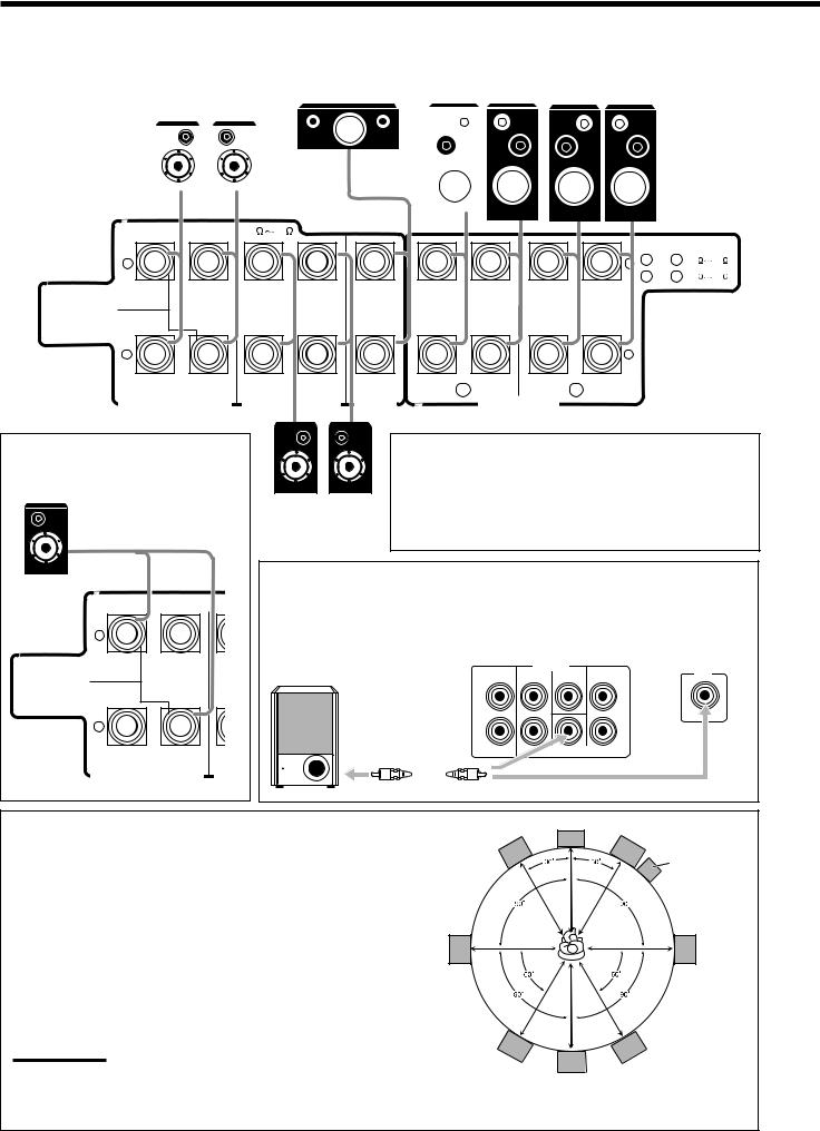
Connecting the Speakers
You can connect the following speakers:
•Two pairs of front speakers to produce normal stereo sound.
•One pair of surround speakers to enjoy the surround effect.
•One surround back speaker or one pair of surround back speakers to enjoy to produce more effective surround effect.
•One center speaker to emphasize human voices.
•One subwoofer to enhance the bass.
CAUTION:
Use only the speakers of the SPEAKER IMPEDANCE indicated by the speaker terminals.
•When connecting to both of the FRONT SPEAKERS 1 and 2 terminals, use speakers with an impedance of 16 Ω to 32 Ω.
•When connecting to either the FRONT SPEAKERS 1 or 2 terminals, use speakers with an impedance of 8 Ω to 16 Ω.
+ –
LEFT
RIGHT
For each speaker (except for a subwoofer), connect the (+) and (–) terminals on the rear panel to the (+) and (–) terminals marked on the speakers.
Speaker layout
Ideal speaker layout varies depending on the conditions of your listening room. The diagram below is a recommended typical example.
Subwoofer
Left front speaker(s) |
Center speaker |
Right front speaker(s) |
(L) |
(C) |
(R) |
Left surround |
Right surround |
speaker (LS) |
speaker (RS) |
Surround back speakers (LSB/RSB)
9
• Rear terminals of RX-8030VBK are used for explanation.
|
|
|
|
|
|
Front speakers 1 |
Front speakers 2 |
|
Surround back speakers* |
Center speaker |
Right / Left |
Right / Left |
|||||
|
Right / Left |
|
|
|
|
|||
|
|
|
|
|
|
|
|
|
|
|
|
|
|
|
|
|
|
|
|
|
|
|
|
|
|
|
CAUTION : SPEAKER IMPEDANCE 8 |
16 |
|
|
|
|
|
|
|
|
|
|
|
||
|
|
|
|
|
|
|
|
|
|
CAUTION : SPEAKER IMPEDANCE |
||||
+ |
|
|
|
|
|
|
|
|
|
+ 1 |
OR |
2 |
: 8 |
16 |
|
|
|
|
|
|
|
|
|
|
1 |
AND |
2 |
: 16 |
32 |
SINGLE USE |
|
|
|
|
|
|
|
|
|
|
|
|
|
|
See Instruction |
|
|
|
|
|
|
|
|
|
|
|
|
|
|
Manual For |
|
|
|
|
|
|
|
|
|
|
|
|
|
|
Connection |
|
|
|
|
|
|
|
|
|
|
|
|
|
|
– |
|
|
|
|
|
|
|
|
|
– |
|
|
|
|
RIGHT |
LEFT |
RIGHT |
LEFT |
CENTER |
RIGHT |
1 |
LEFT |
RIGHT |
2 |
LEFT |
|
|
|
|
|
|
|
|
|
|
|
|
|
|
|
|
|||
SURROUND BACK SPEAKERS |
SURROUNDSPEAKERS |
|
|
FRONT SPEAKERS |
|
|
|
|
|
|
||||
SPEAKER |
|
|
|
|
|
|
|
|
||||||
*When using only one surround back speaker, connect the ª cord to the
RIGHT ª terminal and the · cord to the LEFT · terminal.
CAUTION : SPEAKER IMPEDANCE
+
SINGLE USE
See Instruction
Manual For
Connection
–
RIGHT LEFT
SURROUND BACK SPEAKERS SU
|
IMPORTANT: |
|
|
After connecting the speakers, set the speaker installation |
|
|
information properly. You can use Quick Speaker Setup for |
|
Surround speakers |
easy speaker installation information setting (see page 25). |
|
• To obtain the best possible Surround/DSP effect, see “Setting |
||
Right / Left |
||
the Speakers” on page 27. |
||
|
Connecting the subwoofer speaker
You can enhance the bass by connecting a subwoofer.
Connect the input jack of a powered subwoofer to the rear panel, using a cable with RCA
pin plugs (not supplied).
RX-8030VBK RX-7030VBK RX-7032VSL
PREOUT |
SUBWOOFER |
SURR BACK SURR CENTER FRONT |
OUT |
L |
L |
R |
|
Placing speakers
Front speakers and center speaker
•Place these speakers (position of the mid-range speaker units) at the same height from the floor.
•Point these speakers aiming at the listener’s ears.
Surround and surround back speakers
•Place these speakers at a position which is 1 meter higher than the listener’s ears.
•Point these speakers down aiming at the listener’s ears.
Subwoofer
•You can place it wherever you like since bass sound is non-directional. Normally place it in front of you.
Note:
Ideal speaker layout requires that all speakers be placed at the same distance from the listener. However, since in some places it may be difficult to fulfil this requirement, this unit can adjust the delay time so that the sounds through all the speakers reach the listener with the same timing. (See page 28.)
C
L |
R |
Subwoofer
LS |
RS |
LSB |
RSB |
SB*
*When one surround back speaker is connected.
10
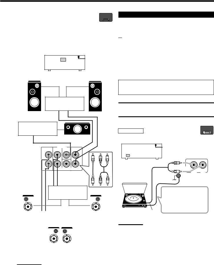
Enhancing your audio system |
RX-8030V |
||||
—Only for RX-8030VBK |
|
ONLY |
|||
|
|
|
|
|
|
|
|
|
|
|
|
You can use this receiver as the pre-amplifier (control amplifier) when you connect power amplifiers to the PREOUT jacks on the rear using cables with RCA pin plugs (not supplied).
•Connect the white plug to the audio left jack, and the red plug to the audio right jack.
Left front speaker |
RX-8030VBK |
Right front speaker |
|
Power amplifier
Power amplifier
Center speaker
|
PREOUT |
FRONT |
|
SURR BACK |
SURR |
CENTER |
|
L |
|
|
|
R L
R
SUBWOOFER
R L
Power amplifier
|
|
|
|
|
|
|
|
|
|
|
|
|
|
|
|
Power amplifier |
|
|
|
|
|||||
Left surround |
|
Right surround |
||||||||||
|
speaker |
|
|
|
|
|
|
|
speaker |
|||
|
|
|
|
|
|
|
|
|
|
|
|
|
|
|
|
|
|
|
|
|
|
|
|
|
|
|
|
|
|
|
|
|
|
|
|
|
|
|
Surround back speakers
Left / Right
Note:
If you connect one surround back speaker, connect the surround back speaker to the left surround back PREOUT jack (SURR BACK L).
Connecting Audio/Video Components
When connecting individual components, refer also to the manuals supplied with them.

 Analog Connections
If your audio components have digital audio output terminal, connecting them using the digital cords explained in “Digital Connections” (see page 16) will give you better sound quality.
Audio component connections
Use the cables with RCA pin plugs (not supplied).
•Connect the white plug to the audio left jack, and the red plug to the audio right jack.
If your audio components have a COMPU LINK jack
See also page 41 for detailed information about the connection and the COMPU LINK remote control system.
CAUTION:
If you connect a sound-enhancing device such as a graphic equalizer between the source components and this receiver, the sound output through this receiver may be distorted.
RX-8030V
ONLY
Turntable
To listen to the sound after connection, press PHONO.
RX-8030VBK |
R |
|
|
L |
LEFT |
|
|
Turntable
If a ground cable is
provided for your turntable,
connect the cable to the
screw marked (H) on the
rear.
To audio output
Note:
This connection is for the turntable with an MM (moving-magnet) type cartridge.
Any turntables incorporating a small-output cartridge such as an MC
(moving-coil) type must be connected to this receiver through a commercial head amplifier or step-up transformer. Direct connection may result in insufficient volume.
11
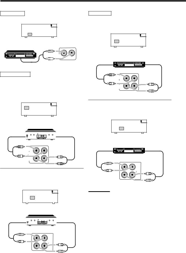
CD player
To listen to the sound after connection, press CD.
RX-8030VBK
RX-7030VBK/RX-7032VSL
CD player


 R
R 


 L
L 

To audio output
Cassette deck
To listen to the sound after connection, press TAPE/MD (for RX8030VBK) or TAPE/CDR (for RX-7030VBK/RX-7032VSL).
For RX-8030VBK
You can connect either a cassette deck or an MD recorder to the TAPE/MD jacks. When connecting an MD recorder, see page 13.
RX-8030VBK
Cassette deck
To audio input 


 To audio output
R |
|
|
L |
IN |
L |
|
||
|
|
|
|
(PLAY) |
|
|
|
R |
For RX-7030VBK/RX-7032VSL
You can connect either a cassette deck or a CD recorder to the TAPE/CDR jacks. When connecting an CD recorder to the TAPE/ CDR jacks, see the right column.
RX-7030VBK/RX-7032VSL
Cassette deck
To audio input 


 To audio output


 R
R 

|
OUT |
|
(REC) |
L |
TAPE |
|
CDR |
|
L |
 R
R 


12
CD recorder
To listen to the sound after connection, press CDR (for RX-8030VBK) or TAPE/CDR (for RX-7030VBK/RX-7032VSL).
For RX-8030VBK
RX-8030VBK
CD recorder
To audio input  To audio output
R |
|
L |
L |
|
|
|
IN |
|
(PLAY) |
 R
R 


For RX-7030VBK/RX-7032VSL
You can connect either a CD recorder or a cassette deck to the TAPE/CDR jacks. When connecting a cassette deck to the TAPE/ CDR jacks, see the left column.
RX-7030VBK/RX-7032VSL
CD recorder
To audio input  To audio output


 R
R 

|
OUT |
|
(REC) |
L |
TAPE |
|
CDR |
|
L |
 R
R 


Note:
For RX-7030VBK/RX-7032VSL: When connecting a CD recorder to the TAPE/CDR jacks, change the source name to “CDR,” which will be shown on the display when it is selected as the source. See page 21 for details.
MD recorder
To listen to the sound after connection, press TAPE/MD (for RX8030VBK) or TAPE/CDR (for RX-7030VBK/RX-7032VSL).
For RX-8030VBK
You can connect either an MD recorder or a cassette deck to the TAPE/MD jacks. When connecting a cassette deck, see page 12.
RX-8030VBK
MD recorder
To audio input  To audio output
R |
|
|
L |
IN |
L |
|
||
|
|
|
|
(PLAY) |
|
|
|
R |
Note:
When connecting an MD recorder to the TAPE/MD jacks, change the source name to “MD,” which will be shown on the display when it is selected as the source. See page 21 for details.
For RX-7030VBK/RX-7032VSL
You can connect an MD recorder to the TAPE/CDR jacks if they are not used for connecting another component such as a cassette deck or CD recorder. When connecting an MD recorder to the TAPE/ CDR jacks, see page 12.
•Though your MD recorder is one of JVC products with the COMPU LINK remote control system, you cannot use the COMPU LINK remote control system to operate the connected MD recorder.
Video component connections
Use the cables with RCA pin plugs (not supplied).
Connect the white plug to the audio left jack, the red plug to the audio right jack, and the yellow plug to the video jack.
•If your video components have S-video (Y/C-separation) and/or component video (Y, PB, PR) terminals, connect them using an S- video cable (not supplied) and/or component video cable (not supplied). By using these jacks, you can get better picture quality in the order—Component video > S-video > Composite video.
If your video components have an AV COMPULINK jack
See also page 42 for detailed information about the connection and the AV COMPU LINK remote control system.
IMPORTANT:
This receiver is equipped with the following video jacks—composite video, S-video and component video jacks. You can use any of the three to connect a video component.
However, the video signals from one type of these input jacks are transmitted only through the video output jacks of the same type.
Therefore, if a recording video component and a playing video component are connected to the receiver through the video jacks of different type, you cannot record the picture. In addition, if the TV and a playing video component are connected to the receiver through the video jacks of different type, you cannot view the playback picture on the TV.
Video camera |
ONLY |
||
|
RX-8030V |
||
|
|
|
|
|
|
|
|
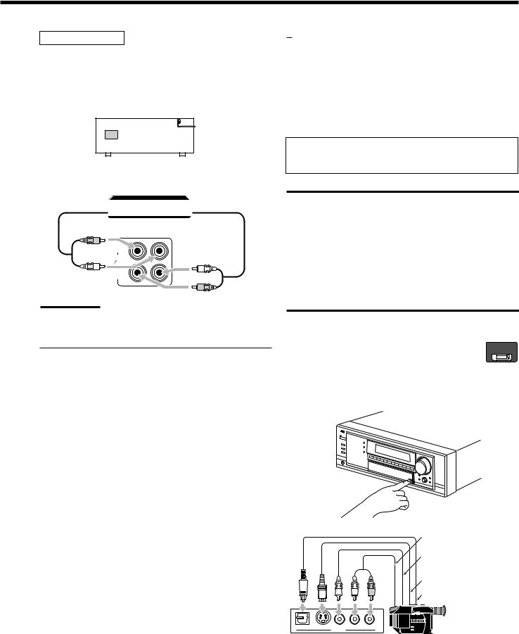
To listen to the sound after connection, press VIDEO.
The VIDEO input jacks on the front panel (inside the front door) are convenient when connecting and disconnecting the component frequently.
L R
To audio output
To composite video output
To S-video output
To optical digital output
DIGITAL S-VIDEO VIDEO L—AUDIO—R
VIDEO
Video camera
When using the digital input terminal
Select the digital input mode correctly.
For details, see “Selecting the Analog or Digital Input Mode” on page 19.
13
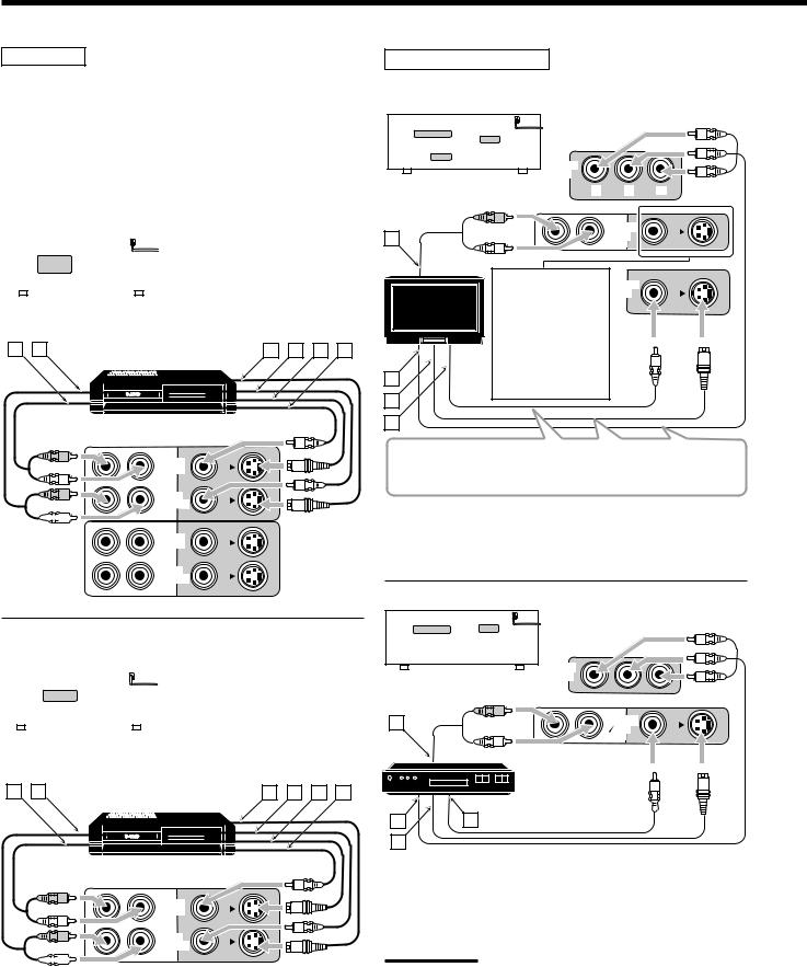
VCR(s)
To listen to the sound after connection, press VCR 1 or VCR 2 (for RX-8030VBK) or VCR (for RX-7030VBK/RX-7032VSL).
For RX-8030VBK
You can connect two VCRs—one to the VCR 1 jacks and the other to the VCR 2 jacks.
•If your VCR has an AV COMPU LINK jack, connect it to the VCR 1 jack so that you can use the AV COMPU LINK remote control system.
|
|
|
|
|
|
|
Å To audio input |
||
|
|
|
|
|
|
|
|||
|
|
|
|
|
|
|
|||
|
|
|
|
|
|
|
ı To audio output |
||
|
|
|
|
|
|
|
|||
|
|
|
|
|
|
|
Ç To S-video output |
||
|
|
|
|
|
|
|
Î To composite video output |
||
|
|
RX-8030VBK |
|
|
|||||
|
|
|
|
‰ To S-video input |
|||||
|
|
|
|
||||||
|
|
|
|
|
|
|
Ï To composite video input |
||
A B |
|
|
|
|
C D E F |
||||
|
|
|
|
|
|
VCR |
|||
|
|
|
|
|
|
|
|
|
|
|
|
|
|
|
|
|
|
|
|
|
|
|
|
|
|
|
|
|
|
|
|
|
|
|
|
|
|
|
|
|
|
|
|
|
|
|
|
|
|
|
|
|
|
|
|
|
|
|
|
R |
OUT |
|
|
|
(REC) |
L |
VCR 1 |
|
R |
IN |
(PLAY)


 L
L 

OUT (REC)
VCR 2
IN (PLAY)
For RX-7030VBK/RX-7032VSL |
|
|
|
|||||||||||
|
|
|
|
|
|
|
|
|
|
|
|
Å To audio input |
||
|
|
|
|
|
|
|
|
|
|
|
|
|||
|
|
|
|
|
|
|
|
|
|
|
|
|||
|
|
|
|
|
|
|
|
|
|
|
|
ı To audio output |
||
|
|
|
|
|
|
|
|
|
|
|
|
|||
|
|
|
|
|
|
|
|
|
|
|
|
Ç To S-video output |
||
|
|
|
|
|
|
|
|
|
|
|
|
Î To composite video output |
||
|
|
|
|
|
|
|
|
|
|
|
|
|||
|
|
|
|
|
‰ To S-video input |
|||||||||
RX-7030VBK/RX-7032VSL |
||||||||||||||
|
|
|
|
|
|
|
|
|
|
|
|
Ï To composite video input |
||
A B |
|
|
VCR |
|
C D E F |
|||||||||
|
|
|
|
|
|
|
|
|
|
|
|
|||
|
|
|
|
|
|
|
|
|
|
|
|
|
|
|
|
|
|
|
|
|
|
|
|
|
|
|
|
|
|
|
|
|
|
|
|
|
|
|
|
|
|
|
|
|
|
|
|
|
|
|
|
|
|
|
|
|
|
|
|
|
|
|
|
|
|
|
|
|
|
|
|
|
|
|
|
|
|
|
|
|
|
|
|
|
|
|
|
|
|
R |
OUT |
|
(REC) |
L |
VCR |
|
R |
IN |
(PLAY)


 L
L 

14
TV and/or DBS tuner
To listen to the sound after connection, press TV SOUND/DBS (or TV/DBS on the remote control).
|
|
MONITOR |
|
|
|
|
|
|
OUT |
|
|
|
|
|
RX-8030VBK |
Y |
PB |
PR |
||
RX-7030VBK/RX-7032VSL |
||||||
|
|
|
||||
|
|
R |
|
TV SOUND |
|
|
|
|
|
|
|
||
A |
|
|
|
DBS |
|
|
|
L |
|
IN |
|
||
|
|
|
|
|
||
|
TV |
|
|
|
|
|
|
|
When connecting |
|
MONITOR |
|
|
|
TV |
the TV to the |
|
OUT |
|
|
|
|
|
|
|||
|
AUDIO jacks (TV |
|
|
|
||
|
|
|
|
|
||
|
|
SOUND/DBS IN), |
|
|
|
|
|
|
DO NOT connect |
|
|
|
|
|
|
the TV’s video |
|
|
|
|
B |
|
output to these |
|
|
|
|
|
video input jacks. |
|
|
|
||
|
|
|
|
|
||
C
Connect the TV to appropriate MONITOR OUT jacks to view the playback picture from any other connected video components.
Å To audio output
ı To component video input Ç To S-video input
Î To composite video input
DBS
RX-8030VBK IN
RX-7030VBK/RX-7032VSL
A |
|
R |
TV SOUND |
|
|
||
|
|
DBS |
|
|
|
L |
IN |
|
|
|
|
|
DBS |
|
DBS tuner |
|
|
|
|
B |
|
D |
|
C |
|
|
|
Å To audio output
ı To component video output Ç To S-video output
Î To composite video output
Notes:
•When connecting a DBS tuner to the TV SOUND/DBS IN jacks, change the source name to “DBS,” which will be shown on the display when selected as the source. Otherwise you cannot view any picture from DBS tuner. See page 21 for details.
•When connecting a DBS tuner to either one of the component input jacks, make the component video input setting correctly for AV COMPU LINK. See page 30 for details.
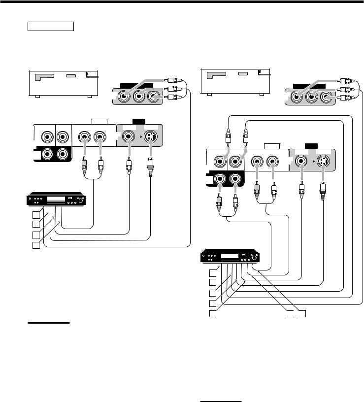
DVD player
•When you connect a DVD player with stereo output jacks:
To listen to the sound after connection, press DVD.
|
|
DVD |
|
RX-8030VBK |
|
IN |
|
|
|
|
|
RX-7030VBK/RX-7032VSL |
|
|
|
|
AUDIO |
|
VIDEO |
SUBWOOFER CENTER |
RIGHT LEFT |
VIDEO |
S-VIDEO |
|
|
DVD |
|
DVD |
|
IN |
|
|
FRONT |
|
|
IN |
|
|
|
SURR (REAR)
R L
DVD player
DVD |
A
B
C
D
Å To component video output ı To S-video output
Ç To composite video output
ÎTo left/right front channel audio output (or to audiomixed output if necessary)
Note:
When connecting a DVD player to the component video input jacks, make the component video input setting correctly for AV COMPU LINK. See page 30 for details.
•When you connect a DVD player with its analog discrete output (5.1-channel reproduction) jacks:
To listen to the sound after connection, press DVD MULTI.
DVD
RX-8030VBK IN
RX-7030VBK/RX-7032VSL
|
|
AUDIO |
|
VIDEO |
SUBWOOFER CENTER |
RIGHT |
LEFT |
VIDEO |
S-VIDEO |
|
|
|
DVD |
|
DVD |
|
|
IN |
|
|
|
FRONT |
|
|
IN |
|
|
|
|
SURR (REAR)
R L
R L
DVD player
DVD |
A 

B
C
D
E 
 F
F 
 G
G
Å To component video output ı To subwoofer output
Ç To center channel audio output Î To S-video output
‰ To composite video output
Ï To left/right front channel audio output
Ì To left/right surround channel audio output
Note:
When connecting a DVD player to the component video input jacks, make the component video input setting correctly for AV COMPU LINK. See page 30 for details.
15

 Digital Connections
This receiver is equipped with four DIGITAL IN terminals—one digital coaxial terminal and three digital optical terminals—and one DIGITAL OUT (optical) terminal on the rear.
•For RX-8030VBK: Another digital optical input terminal is located on the front panel (see page 13).
IMPORTANT:
•When connecting a DVD player, digital TV broadcast tuner or DBS tuner using the digital terminals, you also need to connect it to the video jacks on the rear. Without connecting it to the video jacks, you can view no playback picture.
•After connecting the components using the DIGITAL IN terminals, set the following correctly if necessary.
–Set the digital input (DIGITAL IN) terminal setting correctly. For details, see “Setting the Digital Input Terminals” on page 29.
–Select the digital input mode correctly. For details, see “Selecting the Analog or Digital Input Mode” on page 19.
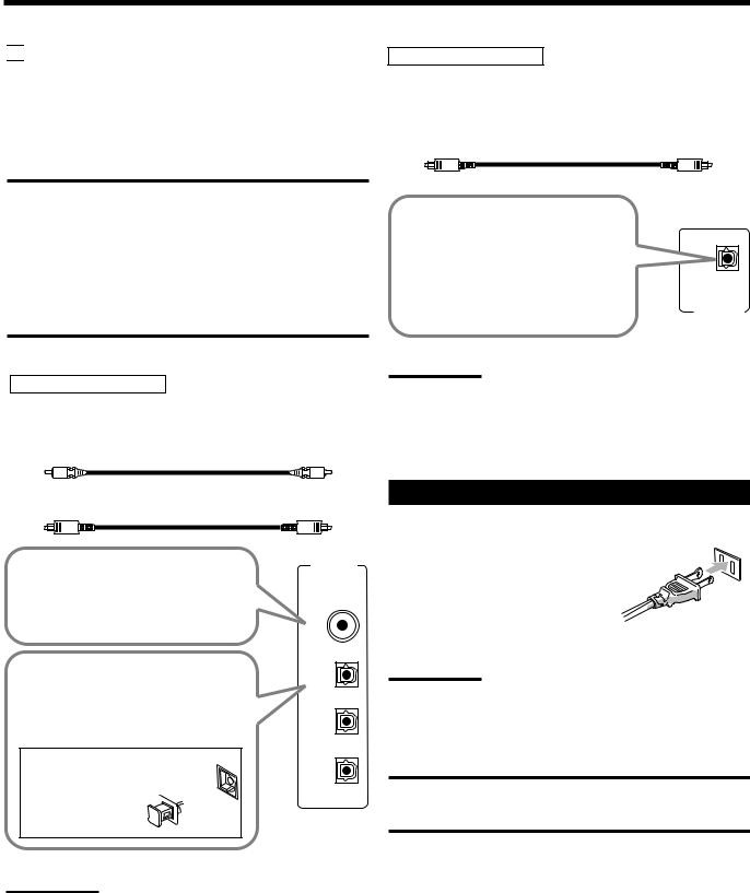
Digital input terminals
You can connect any digital components having coaxial or optical digital output terminal.
Digital coaxial cable (not supplied) between digital coaxial terminals
Digital optical cable (not supplied) between digital optical terminals
DIGITAL IN
When the component has a digital coaxial output terminal, connect it to the DIGITAL 1 (DVD) terminal, using a digital coaxial cable (not supplied).
DIGITAL 1 (DVD)
When the component has a digital optical output terminal, connect it to the DIGITAL 2 (CD), DIGITAL 3 (TV) or DIGITAL 4 (CDR) terminal, using a digital optical cable (not supplied).
Before connecting a digital optical cable, unplug the protective plug. 

Notes:
DIGITAL 2 (CD)
DIGITAL 3 (TV)
DIGITAL 4 (CDR)
•When shipped from the factory, the DIGITAL IN terminals have been set for use with the following components:
–DIGITAL 1 (coaxial): For DVD player
–DIGITAL 2 (optical): For CD player
–DIGITAL 3 (optical): For digital TV broadcast tuner
–DIGITAL 4 (optical): For CD recorder
•When you want to operate the CD player or CD recorder, (or MD recorder: only for RX-8030VBK) using the COMPU LINK remote control system, connect the target component also as described in “Analog Connections” (see pages 12 and 13).
•When you want to operate a DVD player using the AV COMPU
LINK remote control system (see page 42), connect the DVD player also as described in “Analog Connections” (see page 15).
Digital output terminal
You can connect any digital components which have an optical digital input terminal.
Digital optical cable (not supplied) between digital optical terminals
When the digital recording equipment such as an MD recorder and CD recorder has a digital optical input terminal, connecting it
to the DIGITAL OUT terminal |
DIGITAL |
|
|
enables you to perform digital-to- |
|
digital recording. |
OUT |
|
Note:
The digital signal format transmitted through the DIGITAL OUT terminal is the same as that of the input signal. This means that when the DTS Digital Surround signals are input, the DTS Digital Surround signals are transmitted.
Connecting the Power Cord
Before plugging the receiver into an AC outlet, make sure that all connections have been made.
Plug the power cord into an AC outlet.
Keep the power cord away from the connecting cables and the antenna. The
power cord may cause noise or screen interference.
Note:
The preset settings such as preset channels and sound adjustment may be erased in a few days in the following cases:
–When you unplug the power cord.
–When a power failure occurs.
CAUTIONS:
•Do not touch the power cord with wet hands.
•Do not pull on the power cord to unplug the cord. When unplugging the cord, always grasp the plug so as not to damage the cord.
16

 Basic Operations
The following operations are commonly used when you play any sound sources.
Operations hereafter will be explained using the buttons on the front panel.
You can also use the buttons on the remote control for the same functions if they have the same and similar names/marks.
Daily Operational Procedure |
Selecting the Source to Play |
1 |
4 |
3 |
|
|
|
|
|
2 |
1Turn on the power.
•See “Turning On the Power” below.
2Select the source.
•See “Selecting the Source to Play” to the right.
3Adjust the volume.
•See “Adjusting the Volume” on page 18.
4Select the surround or DSP modes.
•See “Activating the Surround Modes” (page 37) and “Activating the DSP Modes” (page 39).
Turning On the Power
Press  STANDBY/ON (or AUDIO
  on the remote control).
The STANDBY lamp goes off. The name of the current source and Surround/DSP mode appear on the display.
Current source name and Surround/DSP mode appear
ANALOG
L |
R LINEAR PCM |
SPEAKERS 1
VOLUME
Current volume level appears.
To turn off the power (into standby mode),
press  STANDBY/ON (or AUDIO
  on the remote control) again.
The STANDBY lamp lights up.
Note:
A small amount of power is consumed in standby mode. To turn off the power completely, unplug the AC power cord.
Press one of the source selection buttons.
•The selected source name and the previously selected Surround/ DSP mode also appear on the display.
Selected source name and current
Surround/DSP mode appear.
|
|
|
|
|
|
|
|
|
|
|
|
|
|
|
|
|
|
|
|
|
|
|
|
|
|
|
|
DUAL |
ANALOG DIGITAL AUTO |
|
96/24 MULTI |
|
|
|
|
TUNED |
|
STEREO |
AUTO MUTING |
ONETOUCH OPERATION |
SLEEP |
|
|||||||||||
|
L |
C |
R |
LINEAR PCM |
|
|
|
|
|
|
PRO LOGIC |
NEO:6 VIRTUAL SB MIDNIGHT MODE DIGITAL EQ |
|
|||||||||||||
|
SUBWFR |
LFE |
|
|
|
|
|
|
|
|
DSP |
3D - PHONIC HEADPHONE |
SPEAKERS 1 2 BASS BOOST |
|
||||||||||||
|
DIGITAL |
|
|
|
|
|
|
|
||||||||||||||||||
|
LS |
S |
RS |
|
|
|
|
|
|
|
|
|
|
|
|
|
|
|
INPUT ATT |
|
|
|
||||
|
|
|
|
|
|
|
|
|
|
|
|
|
|
|
|
|
|
|
||||||||
|
|
|
SB |
|
|
|
|
|
|
|
|
|
|
|
|
|
|
|
|
|
|
|
|
|||
|
|
|
|
|
|
|
|
|
|
|
|
|
|
|
|
|
|
|
|
|
VOLUME |
|
|
|
||
|
|
|
|
|
|
|
|
|
|
|
|
|
|
|
|
|
|
|
|
|
|
|
|
|||
|
|
|
|
|
|
|
|
|
|
|
|
|
|
|
|
|
|
|
|
|
|
|
|
|
|
|
For RX-8030VBK |
|
|
|
|
|
|
|
|
|
|
|
|
|
|
|
|
||||||||||
DVD MULTI |
|
DVD |
|
|
VCR 1 |
|
VCR 2 |
|
VIDEO |
|
TV SOUND |
|
PHONO |
|
CD |
|
CDR |
|
TAPE/MD |
|
FM |
|
AM |
|||
|
|
|
|
|
|
|
|
|
|
|
|
|||||||||||||||
|
|
|
|
|
|
/DBS |
|
|
|
|
|
|
||||||||||||||
|
|
|
|
|
|
|
|
|
|
|
|
|
|
|
|
|
|
|
|
|
|
|
|
|
|
|
On the unit
•The lamp on the selected source lights up (ex. when DVD is selected as the source).
|
|
DVD MULTI |
DVD |
CD |
|
FM/AM |
|
|
|
|
VCR1 |
VCR2 |
CDR |
TAPE/MD |
|
|
|
|
|
TV/DBS |
VIDEO PHONO |
|
|
|
||
|
|
On the remote |
|
|
|
|||
For RX-7030VBK/RX-7032VSL |
|
|
|
|
||||
DVD MULTI |
DVD |
VCR |
TV SOUND/DBS |
CD |
TAPE/CDR |
FM |
AM |
|
|
|
|
On |
the unit |
|
|
|
|
|
|
DVD MULTI |
DVD |
CD |
FM/AM |
|
|
|
TV/DBS VCR TAPE/CDR
On the remote
Notes:
•For RX-8030VBK: When connecting an MD recorder (to the TAPE/ MD jack) and a DBS tuner (to the TV SOUND/DBS jacks), change the source names shown on the display. For details, see page 21.
•For RX-7030VBK/RX-7032VSL: When connecting an CD recorder (to the TAPE/CDR jacks) and a DBS tuner (to the TV SOUND/DBS jacks), change the source names shown on the display. For details, see page 21.
17
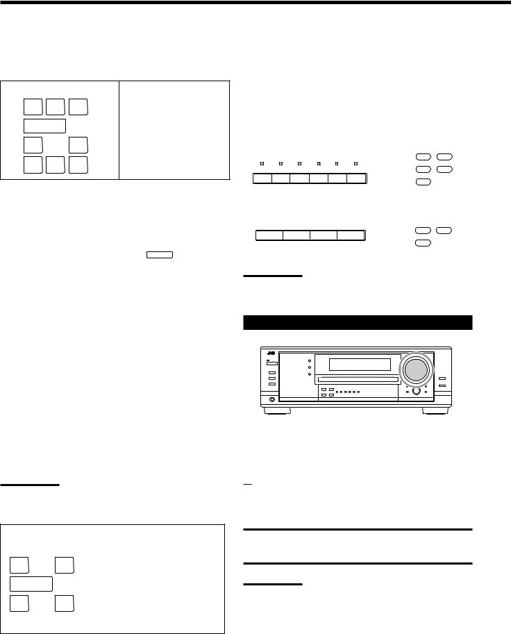
Speaker and signal indicators on the display
By checking the following indicators, you can easily confirm which speakers you are activating and which signals are coming into this receiver.
Speaker indicators |
Signal indicators |
|||
L C |
R |
L |
C |
R |
SUBWFR |
|
|
|
LFE |
LS |
RS |
LS |
S |
RS |
SB |
|
|
SB |
|
What speaker indicators light depends on the speaker setting (for details, see “Setting the Speakers” on page 27).
•The frames of “L,” “C,” “R,” “LS,” “RS, ” and “SB” light up, when the corresponding speakers are set to “LARGE” or “SMALL” and when the speaker is required for the Surround/DSP mode currently selected.
•When “SUB WOOFER” is set to “YES,” SUBWFR lights up (see page 27).
•All three frames on the row of “SB” are not used at the same time. When “SBACK OUT” is set to “2SPK,” the left and the right ones are used. When it is set to “1SPK,” the middle one is used (see page 27).
The signal indicators light up to show the incoming signals. L: • When digital input is selected: Lights up when the left
channel signal comes in.
• When analog input is selected: Always lights up.
R: • When digital input is selected: Lights up when the right channel signal comes in.
• When analog input is selected: Always lights up.
C: Lights up when the center channel signal comes in. LFE: Lights up when the LFE channel signal comes in.
LS: Lights up when the left surround channel signal comes in. RS: Lights up when the right surround channel signal comes in. S: Lights up when the monaural surround channel signal
comes in.
SB: Lights up when the surround back channel signal comes in.
Note:
When “DVD MULTI” is selected as the source, “L,” “C,” “R,” “LFE,” “LS,” and “RS” light up.
How to understand the speaker and signal indicator illumination
L |
C R |
Ex. No sound comes out of the |
SUBWFR LFE |
center speaker and surround |
|
back speakers though center |
||
LS |
RS |
channel and surround back |
channel signals are coming |
||
into this receiver.
SB
Selecting different sources for picture and sound
While watching pictures from a video source, you can listen to sound of an audio source.
•Once you have selected a video source, pictures of the selected source are sent to the TV until you select another video source.
Press one of the audio source selection buttons while viewing the picture from a video component such as the VCR or DVD player, etc.
For RX-8030VBK |
|
|
CD |
FM/AM |
|
|
|
|
|
CDR |
TAPE/MD |
PHONO |
CD CDR |
TAPE/MD FM |
AM |
PHONO |
|
|
|
||||
|
On the unit |
|
On the remote |
||
For RX-7030VBK/RX-7032VSL |
|
|
|||
|
|
|
|
CD |
FM/AM |
CD |
TAPE/CDR |
FM |
AM |
TAPE/CDR |
|
|
|
|
|
|
|
|
On the unit |
|
On the remote |
||
Note:
When you see the picture through the COMPONENT VIDEO jacks, you cannot use this function.
Adjusting the Volume
On the front panel:
To increase the volume, turn MASTER VOLUME clockwise. To decrease the volume, turn it counterclockwise.
From the remote control:
To increase the volume, press VOLUME +.
To decrease the volume, press VOLUME –.
CAUTION:
Always set the volume to the minimum before starting any sources. If the volume is set at its high level, the sudden blast of sound energy can permanently damage your hearing and/or ruin your speakers.
Notes:
•The volume level can be adjusted within the range of “0” (minimum) to “70” (maximum).
•If you set One Touch Operation to “ON” (see page 30), you do not have to adjust the volume level each time you change the source. It is automatically set to the stored level.
18
Selecting the Front Speakers |
Remote |
|
NOT |
When you have connected two pairs of the front speakers, you can select which to use.
To use the speakers connected to the FRONT SPEAKERS 1 terminals, press SPEAKERS ON/OFF 1 so that the SPEAKERS 1 indicator lights up on the display. Make sure that the SPEAKERS 2 indicator is not lit on the display.
To use the speakers connected to the FRONT SPEAKERS 2 terminals, press SPEAKERS ON/OFF 2 so that SPEAKERS 2 indicator lights up on the display. Make sure that the SPEAKERS 1 indicator is not lit on the display.
To use both sets of the speakers, press SPEAKERS ON/OFF 1 and SPEAKERS ON/OFF 2 so that the SPEAKERS 1/2 indicators light up on the display.
To use neither sets of the speakers, press SPEAKERS ON/OFF 1 and SPEAKERS ON/OFF 2 so that the SPEAKERS 1/2 indicators go off from the display.
The HEADPHONE indicator lights up and “HEADPHONE” appears on the display.
•Activating the speakers turns on the Surround and DSP modes previously selected.
Listening with headphones only:
Deactivate both sets of the front speakers, and connect headphones to the PHONES jack.
You can enjoy the sound effects through the headphones when Surround or DSP mode is activated—3D HEADPHONE
(3D H PHONE) mode.
•“3D H PHONE” appears on the display and the DSP and HEADPHONE indicator lights up on the display. (For details, see page 36.)
Note:
When you select “DVD MULTI” as the source or any one of the Surround/DSP mode which activates the center and/or surround speaker(s), you can use only one set of the speakers.
CAUTION:
Be sure to turn down the volume:
•Before connecting or putting on headphones, as its high volume can damage both the headphones and your hearing.
•Before turning on speakers again, as its high volume may come out of the speakers.
Activating and Adjusting the |
Remote |
Subwoofer Sound |
NOT |
|
You can cancel the subwoofer sound even though you have connected a subwoofer and have set “SUB WOOFER” to “YES” (see page 27). This is useful when enjoying surround sound at night.
Press SUBWOOFER OUT ON/OFF to cancel the subwoofer sound output.
Each time you press the button, subwoofer sound output is deactivated (“SUBWFR OFF”) and activated (“SUBWFR ON”) alternately.
•When subwoofer sound output is activated, subwoofer output level can be adjusted using the remote control.
1 Press SOUND.
2 Press SUBWOOFER.
3 Press LEVEL + or – to adjust the output level (–10 dB to +10 dB).
Note:
You cannot deactivate the subwoofer sound output when you set
“SMALL” for the front speakers on the Speaker size setting (see page 27) or Quick Speaker Setup (see page 25).
Selecting the Analog or Digital Input Mode
When you have connected digital source components using the digital terminals (see page 16), change the input mode for these components to the digital input mode.
Before you start, remember...
The digital input terminal setting should be correctly done for the sources you want to select the digital input mode (see “Setting the Digital Input Terminals” on pages 29 and 30).
1.Press one of the source selection buttons for which you want to change the input mode.
• For RX-8030VBK: DVD, VIDEO, TV (SOUND)/DBS, CD, CDR, or TAPE/MD*
• For RX-7030VBK/RX-7032VSL:
DVD, TV (SOUND)/DBS, CD, or TAPE/CDR*
*If “TAPE” is selected as the source, digital input mode is not available. To change the source name, see “Changing the Source
Name” on page 21.
Continued on the next page
19
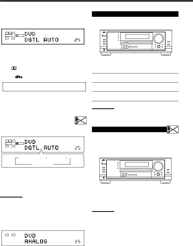
2.Press INPUT DIGITAL (or ANALOG/DIGITAL INPUT on the remote control) to select “DGTL AUTO.”
The DIGITAL AUTO indicator lights up on the display.
|
DIGITAL AUTO |
|
|
L C |
R |
|
|
SUBWFR |
LFE |
DIGITAL |
SPEAKERS 1 |
LS |
RS |
|
|
VOLUME
•When selecting “DGTL AUTO,” the following indicators indicate the digital signal format of the incoming signal.
LINEAR PCM |
: Lights up when Linear PCM signals come |
|
in. |
||
|
||
|
: Lights up when Dolby Digital signals |
|
DIGITAL |
||
come in. |
||
|
||
|
: Lights up when DTS signals come in. |
|
|
||
|
|
No indicator lights up when the receiver cannot recognize the digital signal format of the incoming signals.
When playing software encoded with the Dolby Digital or DTS, the following symptoms may occur:
•Sound does not come out at the beginning of playback.
•Noise comes out while searching for or skipping chapters or tracks.
In this case, press INPUT DIGITAL repeatedly to select |
Remote |
|
“DGTL D.D” or “DGTL DTS” while “DGTL AUTO” |
||
NOT |
||
still remains on the display. |
|
•As you press INPUT DIGITAL, the input mode changes as follows:
|
DIGITAL AUTO |
|
|
L C |
R |
|
|
SUBWFR |
LFE |
DIGITAL |
SPEAKERS 1 |
LS |
RS |
|
|
DGTL AUTO |
|
DGTL D.D |
|
|
|
||
(Digital) |
|
(Dolby Digital) |
|
 DGTL DTS
When “DGTL D.D” or “DGTL DTS” is selected, the AUTO indicator goes off, and the corresponding digital signal format indicator lights up on the display.
•If the incoming signal does not match the selected digital signal format, the frame of the selected indicator will flash.
Note:
When you turn off the power or select another source, “DGTL D.D” and “DGTL DTS” settings are canceled and the digital input mode is automatically reset to “DGTL AUTO.”
To select the analog input mode again
Press INPUT ANALOG (or press ANALOG/DIGITAL INPUT on the remote control repeatedly until “ANALOG” appears on the display). The ANALOG indicator lights up.
ANALOG
L |
R LINEAR PCM |
SPEAKERS 1
VOLUME
Setting the Dynamic Range
You can enjoy a powerful sound at night using the Midnight Mode.
Press MIDNIGHT MODE so that “MID NIGHT 1” or “MID NIGHT 2” appears on the display.
The MIDNIGHT MODE indicator also lights up.
MID NIGHT 1: Select when you want to reduce the dynamic range a little.
MID NIGHT 2: Select when you want to apply the compress effect fully (useful at midnight).
MID NIGHT OFF: Select when you want to enjoy surround with its full dynamic range (no effect applied).
Notes:
•If Analog Direct is in use, Midnight Mode is temporarily canceled.
•Midnight Mode is not valid for DVD MULTI playback mode.
Attenuating the Input Signal |
Remote |
NOT |
When the input level of the analog source is too high, the sounds will be distorted. If this happens, you need to attenuate the input signal level to prevent the sound distortion.
•Once you have made adjustment, it is memorized for each analog source.
Press and hold INPUT ATT (INPUT ANALOG) so that the INPUT ATT indicator lights up on the display.
•Each time you press and hold the button, the input attenuator mode turns on (“ATT ON”) or off (“NORMAL”).
Note:
This function is not valid when “DVD MULTI” is selected or when
Analog Direct is activated.
20
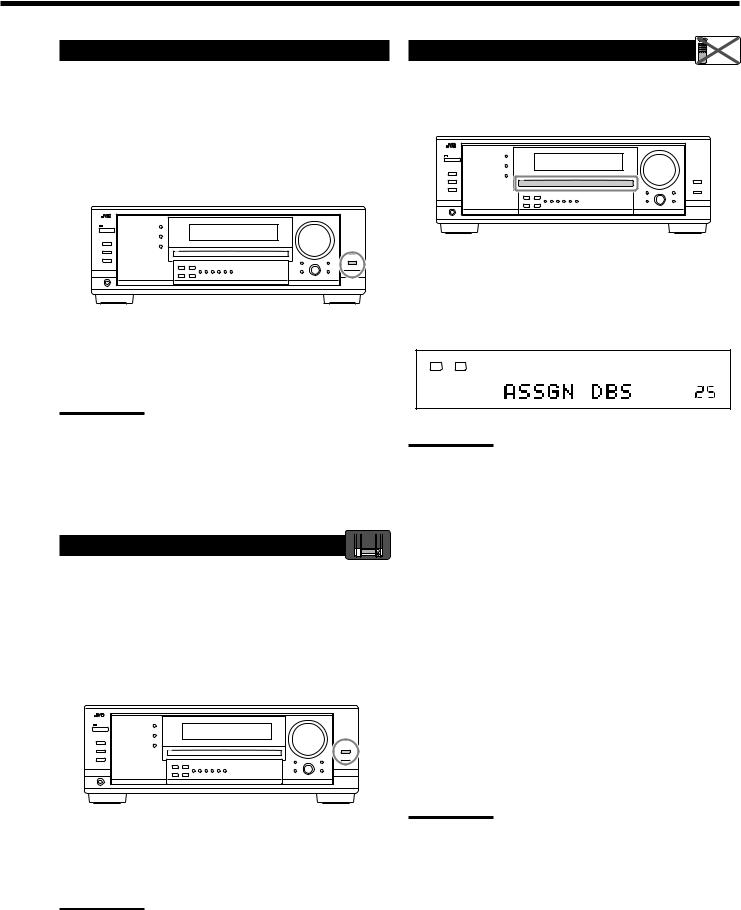
Turning Analog Direct On and Off |
Changing the Source Name |
Remote |
NOT |
You can enjoy the sound closer to the original source by overriding the sound adjustments such as speaker output level adjustments (see page 32), Digital Equalization (see page 32), Surround and DSP modes (see pages 34 to 39), Bass Boost (see page 22) and Midnight Mode (see page 20). You can only adjust the volume level while Analog Direct is in use.
•Once you have made adjustment, it is memorized for each analog source.
When you have connected an MD recorder to the TAPE/MD jacks or a DBS tuner to the TV SOUND/DBS jacks on the rear panel, change the source name which will be shown on the display.
Press ANALOG DIRECT so that “A DIRECT” appears on the display.
The lamp on the button also lights up.
• Each time you press the button, Analog Direct turns on and off.
Notes:
•When digital input mode is in use, Analog Direct is not available.
•Turning on Surround or DSP mode cancels Analog Direct and previously selected sound adjustments are recalled.
•If Analog Direct is in use, Midnight Mode is temporarily canceled.
•Turning on Analog Direct cancels Input Attenuator (page 20) (and CC Converter for RX-8030VBK: below).
Making Sounds Natural |
RX-8030V |
ONLY |
|
|
JVC’s CC (Compensative Compression) Converter eliminates jitter and ripples, achieving a drastic reduction in digital distortion by processing the digital music data in 24 bit–quantization and by expanding the sampling frequency to 128 kHz (for fs 32 kHz signals)/176.4 kHz (for fs 44.1 kHz signals)/192 kHz (for fs 48 kHz signals).
By using CC Converter, you can obtain a natural sound field from both digital and analog sources.
Press CC CONVERTER so that the lamp on the button lights up.
•Each time you press the button, CC Converter turns on and off (the lamp goes off) alternately.
Note:
You cannot use this function while Analog Direct is in use. If you turn on Analog Direct while this function is in use, this function will be canceled.
When changing the source name from “TV” to “DBS”:
1.Press TV SOUND/DBS.
• Make sure “TV” appears on the display.
2.Press and hold TV SOUND/DBS until “ASSGN DBS” appears on the display.
ANALOG
L |
R LINEAR PCM |
SPEAKERS 1
VOLUME
Note:
When connecting a DBS tuner to the TV SOUND/DBS IN jacks, change the source name to “DBS,” which will be shown on the display when selected as the source. Otherwise you cannot view any picture from DBS tuner.
For RX-8030VBK:
When changing the source name from “TAPE” to “MD”:
1.Press TAPE/MD.
• Make sure “TAPE” appears on the display.
2.Press and hold TAPE/MD until “ASSGN MD” appears on the display.
For RX-7030VBK/RX-7032VSL:
When changing the source name from “TAPE” to “CDR”:
1.Press TAPE/CDR.
• Make sure “TAPE” appears on the display.
2.Press and hold TAPE/CDR until “ASSGN CDR” appears on the display.
To change the source name to “TV” and “TAPE,” repeat the same procedure above.
Note:
Without changing the source name, you can still use the connectedcomponents. However, there may be some inconvenience.
•For RX-8030VBK:
–“TAPE” or “TV” will appear on the display when you select the MD recorder or DBS tuner.
–You cannot use the digital input (see pages 19 and 20) for the MD recorder.
–You cannot use the COMPU LINK remote control system (see pages 41) to operate the MD recorder.
•For RX-7030VBK/RX-7032VSL:
–“TAPE” or “TV” will appear on the display when you select the CD recorder or DBS tuner.
–You cannot use the digital input (see pages 19 and 20) for the
CD recorder.
21
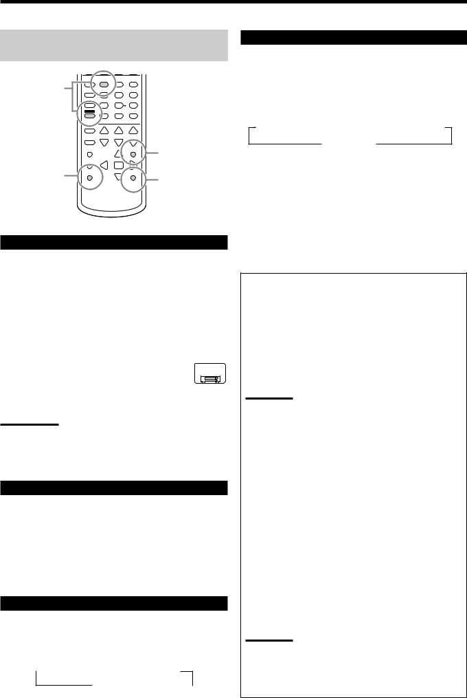
The following basic operations are possible only using the remote control.
|
BASS |
|
|
|
|
BOOST |
|
|
|
Reinforcing the |
1 |
2 |
3 |
|
4 |
5 |
6 |
||
Bass |
||||
|
|
|
||
|
7/P |
8 |
9 |
|
|
SOUND |
0 |
|
|
|
10/0 |
+10 |
|
MUTING |
Muting the |
|
|
|
|
|
Sound |
Using the Sleep |
SLEEP |
Changing |
|
||
Timer |
DIMMER |
|
|
the Display |
|
|
|
|
|
|
Brightness |
Reinforcing the Bass
You can boost the bass level.
• Once you have made adjustment, it is memorized for each source.
1.Press SOUND.
The 10 keys are activated for sound adjustments.
2.Press BASS BOOST to turn on Bass Boost.
The BASS BOOST indicator lights up.
•Each time you press the button, Bass Boost turns on (“BOOST ON”) and off (“BOOST OFF”) alternately.
For RX-7030VBK/RX-7032VSL: |
RX-7030V |
RX-7032V |
ONLY
You can use the BASS BOOST button on the front panel.
When the Bass Boost is activated, the lamp on the button lights up.
• Each time you press the button, Bass Boost turns on and off.
Notes:
•This function affects only the sounds from the front speakers, center speaker, and subwoofer.
•When Analog Direct is in use (see page 21), the Bass Boost is canceled temporarily.
Muting the Sound
Press MUTING to mute the sound through all speakers and headphones connected.
“MUTING” appears on the display and the volume turns off (the VOLUME level indicator goes off).
To restore the sound, press MUTING again.
•Turning MASTER VOLUME on the front panel or pressing VOLUME +/– on the remote control also restores the sound.
Changing the Display Brightness
You can dim the display.
Press DIMMER.
•Each time you press the button, the brightness level of the display change as follows:
 Dimmer
  Much dimmer Canceled
(Normal display)
Using the Sleep Timer
Using the Sleep Timer, you can fall asleep while listening to music. When the shut-off time comes, the receiver turns off automatically.
Press SLEEP repeatedly.
The SLEEP indicator lights up on the display, and the shut-off time changes in 10 minutes intervals:
10  20
20  30
30  40
40  50
50  60
60  70
70  80
80  90
90
0 (Canceled)
To check or change the time remaining until the shut-off time:
Press SLEEP once.
The remaining time until the shut-off time appears in minutes.
• To change the shut-off time, press SLEEP repeatedly.
To cancel the Sleep Timer:
Press SLEEP repeatedly until “SLEEP 0min” appears on the display. (The SLEEP indicator goes off.)
• Turning off the power also cancels the Sleep Timer.
Recording a source
For analog-to-analog recording
You can record any analog playback source onto the recording components connected to the audio output jacks on the rear of this unit at the same time.
For digital-to-digital recording
You can record the currently selected digital input source through the receiver to a digital recording device connected to the DIGITAL OUT terminal.
Notes:
•Analog-to-digital and digital-to-analog recordings are not possible.
•The output volume level, Midnight Mode (see page 20), Bass Boost (see the left column), Digital Equalization (see page 32),
Surround modes and DSP modes (see pages 34 to 39) cannot affect the recording.
Basic adjustment auto memory
This receiver memorizes sound settings for each source—
•when you turn off the power,
•when you change the source, and
•when you assign the source name (see page 21).
When you change the source, the memorized settings for the newly selected source are automatically recalled.
The following can be stored for each source:
•Analog/digital input mode (see pages 19 and 20)
•Input attenuator mode (see page 20)
•Analog Direct (see page 21)
•Digital Equalization (see page 32)
•Speaker channel output levels (see page 32)
•Surround and DSP mode selection (see pages 37 and 39)
•Bass Boost setting (see the left column)
Notes:
•If the source is FM or AM, you can assign a different setting for each band.
•If you want to memorize the volume level with the above settings, set One Touch Operation to “ON” (see page 30).
22
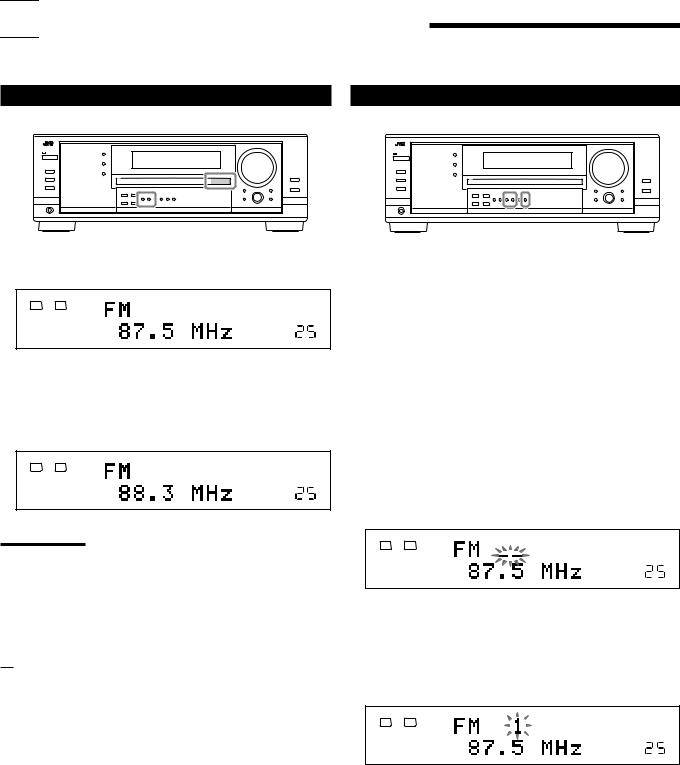

 Receiving Radio Broadcasts
You can browse through all the stations or use the preset function to go immediately to a particular station.
Tuning in to Stations Manually |
Using Preset Tuning |
1. Press FM or AM to select the band.
The last received station of the selected band is tuned in.
|
ANALOG |
TUNED STEREO |
L |
R |
LINEAR PCM |
SPEAKERS 1
VOLUME
2.Press FM/AM TUNING 5 or ∞ repeatedly until you find the frequency you want.
•Pressing FM/AM TUNING 5 increases the frequency.
•Pressing FM/AM TUNING ∞ decreases the frequency.
|
ANALOG |
TUNED STEREO |
L |
R |
LINEAR PCM |
SPEAKERS 1
VOLUME
Notes:
•When a station of sufficient signal strength is tuned in, the TUNED indicator lights up on the display.
•When an FM stereo program is received, the STEREO indicator also lights up.
•When you hold and then release the button in step 2, the frequency keeps changing until a station is tuned in.
From the remote control:
1.Press FM/AM.
•Each time you press the button, the band alternates between FM and AM.
2.Press TUNING UP or TUNING DOWN repeatedly until you find the frequency you want.
•Pressing TUNING UP increases the frequency.
•Pressing TUNING DOWN decreases the frequency.
Once a station is assigned to a channel number, the station can be quickly tuned in. You can preset up to 30 FM and 15 AM stations.
To store the preset stations
Before you start, remember...
There is a time limit in doing the following steps. If the setting is canceled before you finish, start from step 2 again.
On the front panel ONLY:
1.Tune in the station you want to preset (see “Tuning in to Stations Manually” on the left).
•If you want to store the FM reception mode for this station, select the FM reception mode you want. See “Selecting the FM Reception Mode” on page 24.
2.Press MEMORY.
|
ANALOG |
TUNED STEREO |
L |
R |
LINEAR PCM |
SPEAKERS 1
VOLUME
The channel number position starts flashing on the display for about 10 seconds.
3.Press FM/AM PRESET 5 or ∞ to select a channel number while the channel number position is flashing.
|
ANALOG |
TUNED STEREO |
L |
R |
LINEAR PCM |
SPEAKERS 1
VOLUME
4. Press MEMORY again while the selected channel number is flashing on the display.
The selected channel number stops flashing.
The station is assigned to the selected channel number.
5.Repeat steps 1 to 4 until you store all the stations you want.
To erase a stored preset station
Storing a new station on a used number erases the previously stored one
23
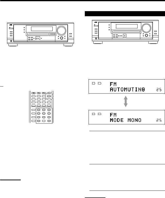
To tune in a preset station
On the front panel:
1. Press FM or AM to select the band.
The last received station of the selected band is tuned in.
Selecting the FM Reception Mode
When an FM stereo broadcast is hard to receive or noisy, you can change the FM reception mode while receiving an FM broadcast.
•You can store the FM reception mode for each preset station (see page 23).
2.Press FM/AM PRESET 5 or ∞ until you find the channel you want.
•Pressing FM/AM PRESET 5 increases the number.
•Pressing FM/AM PRESET ∞ decreases the number.
From the remote control:
1 2 3
4 5 6
7/P 8 9
10/0 |
0 |
+10 |
While listening to an FM station, press FM MODE.
•Each time you press the button, the FM reception mode alternates between “AUTOMUTING” and “MODE MONO.”
|
ANALOG |
TUNED STEREO AUTO MUTING |
L |
R |
LINEAR PCM |
SPEAKERS 1
VOLUME
|
ANALOG |
TUNED |
L |
R |
LINEAR PCM |
SPEAKERS 1
VOLUME
1. Press FM/AM to select the band.
The last received station of the selected band is tuned in.
•Each time you press the button, the band alternates between FM and AM.
2.Press the 10 keys to select a preset channel number.
•For channel number 5, press 5.
•For channel number 15, press +10 then 5.
•For channel number 20, press +10 then 10.
•For channel number 30, press +10, +10, then 10.
Note:
When you use the 10 keys on the remote control, be sure that they are activated for the tuner, not for the CD and others. (See page 44.)
AUTOMUTING: Normally select this.
When a program is broadcasted in stereo, you will hear stereo sound;
when in monaural, you will hear monaural sounds.
This mode is also useful to suppress static noise between stations. The AUTO MUTING indicator lights up on the display. (Initial setting)
MODE MONO: Select this to improve the reception (but stereo effect will be lost).
In this mode, you will hear noise while tuning into the stations. The AUTO MUTING indicator goes off from the display. (The STEREO indicator also goes off.)
Note:
When you use the FM MODE on the remote control, be sure that it is activated for the tuner, not for the CD and others. (See page 44.)
24
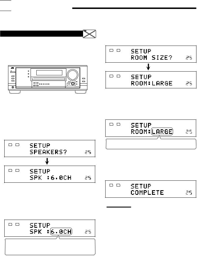

 Basic Settings
Some of the following settings are required after connecting and positioning your speakers while others will make operations easier. You can use QUICK SPEAKER SETUP to easily set up your speaker configuration.
Setting the Speakers Configuration  Remote
NOT
Quick Speaker Setup helps you to easily and quickly register the speaker size and speaker distance according to your listening room to create the best possible surround effect.
•You can also register each speaker’s information manually. For details, see page 27.
3. Press in MULTI JOG (PUSH SET).
“ROOM SIZE?” appear on the display, then the initial room size setting appears.
ANALOG
L |
R LINEAR PCM |
SPEAKERS 1
VOLUME
ANALOG
L |
R LINEAR PCM |
SPEAKERS 1
VOLUME
Before you start, remember...
There is a time limit in doing the following steps. If the setting is canceled before you finish, start from step 1 again.
On the front panel:
1. Press QUICK SPEAKER SETUP.
“SETUP” and “SPEAKERS?” appear on the display, then the initial setting for the total number of the connected speakers (channels) appears.
ANALOG
L |
R LINEAR PCM |
SPEAKERS 1
VOLUME
4. Turn MULTI JOG to select an appropriate room size to match to your listening room.
The room size changes as follows.
•To select your appropriate room size, see “Room size and the speaker distance” on page 26.
ANALOG
L |
R LINEAR PCM |
SPEAKERS 1
VOLUME
SMALL “ MID “ LARGE* “ (Back to the beginning)
* “LARGE” is the initial setting.
ANALOG
L |
R LINEAR PCM |
SPEAKERS 1
VOLUME
2.Turn MULTI JOG to select an appropriate number of the connected speakers (speaker
channel number).
The speaker channel number changes as follows.
•For the details of speaker channel number, see “Speakers (channels) number and the size” on page 26.
ANALOG
L R
SPEAKERS 1
VOLUME
2.0CH “ 2.1CH “ 3.0CH “ 3.1CH “ 4.0CH “ 4.1CH “ 5.0CH “ 5.1CH “ 6.0CH* “ 6.1CH “ 7.0CH “ 7.1CH “ (Back to the beginning)
5. Press in MULTI JOG (PUSH SET).
“COMPLETE” appears on the display, then goes back to the source indication.
• Speaker configuration settings now become active.
ANALOG
L |
R LINEAR PCM |
SPEAKERS 1
VOLUME
Note:
This procedure will not be completed if you stop in the middle of the setting process.
* “6.0CH” is the initial setting.
25

Speakers (channels) number and the size
You can find how each of the speaker size is defined according to the number of connected speakers (speaker channel (CH) number) you select.
In the following tables, “L” stands for “left front speaker,” “R” for “right front speaker,” “C” for “center speaker,” “LS” for “left surround speaker,” “RS” for “right surround speaker,” “SB” for “surround back speaker,” and “SUBWFR” for “subwoofer.”
• Subwoofer is counted as 0.1 channel.
CH |
|
The size of connected speakers |
|
|||||
L |
R |
C |
LS |
RS |
SB |
SUBWFR |
||
|
||||||||
|
|
|
|
|
|
|
|
|
2.0 |
LARGE |
LARGE |
NONE |
NONE |
NONE |
NONE |
NO |
|
|
|
|
|
|
|
|
|
|
2.1 |
SMALL |
SMALL |
NONE |
NONE |
NONE |
NONE |
YES |
|
|
|
|
|
|
|
|
|
|
3.0 |
LARGE |
LARGE |
SMALL |
NONE |
NONE |
NONE |
NO |
|
|
|
|
|
|
|
|
|
|
3.1 |
SMALL |
SMALL |
SMALL |
NONE |
NONE |
NONE |
YES |
|
|
|
|
|
|
|
|
|
|
4.0 |
LARGE |
LARGE |
NONE |
SMALL |
SMALL |
NONE |
NO |
|
|
|
|
|
|
|
|
|
|
4.1 |
SMALL |
SMALL |
NONE |
SMALL |
SMALL |
NONE |
YES |
|
|
|
|
|
|
|
|
|
|
5.0 |
LARGE |
LARGE |
SMALL |
SMALL |
SMALL |
NONE |
NO |
|
|
|
|
|
|
|
|
|
|
5.1 |
SMALL |
SMALL |
SMALL |
SMALL |
SMALL |
NONE |
YES |
|
|
|
|
|
|
|
|
|
|
6.0 |
LARGE |
LARGE |
SMALL |
SMALL |
SMALL |
SMALL |
NO |
|
|
|
|
|
|
|
|
|
|
6.1 |
SMALL |
SMALL |
SMALL |
SMALL |
SMALL |
SMALL |
YES |
|
|
|
|
|
|
|
|
|
|
7.0 |
LARGE |
LARGE |
SMALL |
SMALL |
SMALL |
SMALL* |
NO |
|
|
|
|
|
|
|
|
|
|
7.1 |
SMALL |
SMALL |
SMALL |
SMALL |
SMALL |
SMALL* |
YES |
|
|
|
|
|
|
|
|
|
|
* This setting is applied to the both speakers.
Room size and the speaker distance
According to the selected room size, speaker distance for each activated speaker is set as follows:
LARGE |
Speaker |
Distance |
|
L |
3.0 m (10 ft) |
|
|
|
|
R |
3.0 m (10 ft) |
|
|
|
|
C |
3.0 m (10 ft) |
|
|
|
|
LS |
3.0 m (10 ft) |
|
|
|
|
RS |
3.0 m (10 ft) |
|
|
|
|
SB |
3.0 m (10 ft) |
MID |
Speaker |
Distance |
|
L |
2.7 m (9 ft) |
|
|
|
|
R |
2.7 m (9 ft) |
|
|
|
|
C |
2.4 m (8 ft) |
|
|
|
|
LS |
2.1 m (7 ft) |
|
|
|
|
RS |
2.1 m (7 ft) |
|
|
|
|
SB |
1.8 m (6 ft) |
SMALL |
Speaker |
Distance |
|
L |
2.4 m (8 ft) |
|
|
|
|
R |
2.4 m (8 ft) |
|
|
|
|
C |
2.1 m (7 ft) |
|
|
|
|
LS |
1.5 m (5 ft) |
|
|
|
|
RS |
1.5 m (5 ft) |
|
|
|
|
SB |
1.2 m (4 ft) |
Basic Setting Items
On the following pages, you can adjust the following items:
Items |
To do |
See page |
|
SUB WOOFER*1 |
Register your subwoofer. |
|
27 |
FRONT SPEAKER*1 |
Register your front speaker size. |
|
27 |
CNTR SPEAKER*1 |
Register your center speaker size. |
27 |
|
SURR SPEAKER*1 |
Register your surround speaker size. |
27 |
|
SBACK SPEAKER*1 |
Register your surround back |
|
|
|
speaker size. |
|
27 |
|
|
|
|
SBACK OUT*1 |
Register the number of the |
|
|
|
connected surround back speakers. 27 |
||
|
|
|
|
DIST UNIT |
Select the measuring unit for the |
|
|
|
speaker distance. |
|
28 |
|
|
|
|
FRONT DISTANCE*1 |
Register the distance from you front |
|
|
|
speakers to your listening point. |
|
28 |
|
|
|
|
CNTR DISTANCE*1 |
Register the distance from you center |
|
|
|
speaker to your listening point. |
|
28 |
|
|
|
|
SURR DISTANCE*1 |
Register the distance from you |
|
|
|
surround speakers to your listening |
|
|
|
point. |
|
28 |
|
|
|
|
SBACK DISTANCE*1 Register the distance from you |
|
|
|
|
surround back speaker(s) to your |
|
|
|
listening point. |
|
28 |
|
|
|
|
S WFR OUTPUT |
Select sounds emitted from the |
|
|
|
subwoofer. |
|
28 |
|
|
|
|
CROSS OVER |
Select the cutoff frequency to the |
|
|
|
subwoofer. |
|
28 |
|
|
|
|
LFE ATTENUATE |
Attenuate the bass (LFE) sounds. |
|
29 |
|
|
|
|
DUAL MONO |
Select the Dual Mono sound |
|
|
|
channel. |
|
29 |
|
|
|
|
DGTL IN COAX |
Select the component connected to |
|
|
|
digital coaxial terminal |
|
29 |
|
|
|
|
DGTL IN OPTICAL*2 |
Select the components connected to |
|
|
|
digital optical terminals |
|
29 |
|
|
|
|
VIDEO IN DVD |
Select the type of video terminal |
|
|
|
used for the DVD player. |
|
30 |
|
|
|
|
VIDEO IN DBS |
Select the type of video terminal |
|
|
|
used for the DBS tuner. |
|
30 |
|
|
|
|
ONE TOUCH OPE |
Store the volume level for each |
|
|
|
source. |
|
30 |
|
|
|
|
Notes:
*1 These items can be set using Quick Speaker Setup. *2 This setting is only for RX-8030VBK.
For RX-7030VBK/RX-7032VSL, it is automatically set according to your “DGTL IN COAX” setting.
26
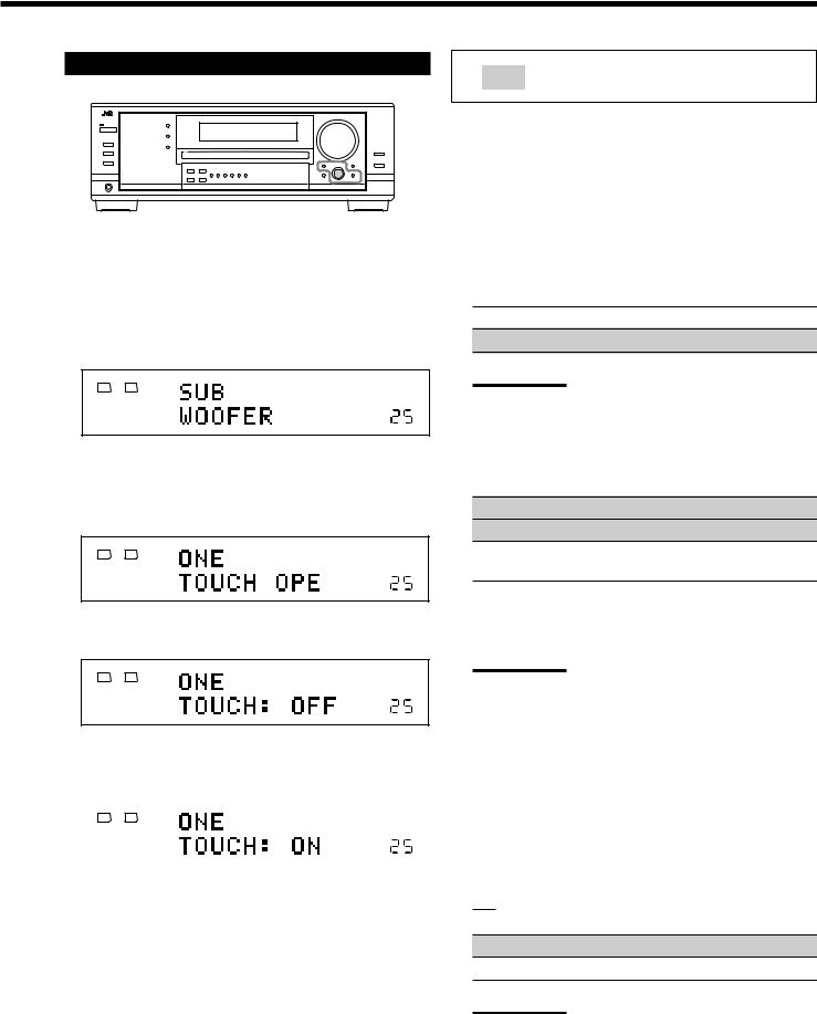
Basic Procedure
Before you start, remember...
There is a time limit in doing the following steps. If the setting is canceled before you finish, start from step 1 again.
Ex. When setting One Touch Operation to “ON.”
1. Press SETTING.
The last selected item appears on the display.
ANALOG
L |
R LINEAR PCM |
SPEAKERS 1
VOLUME
2.Turn MULTI JOG until an item you want appears on the display.
•In this example, select “ONE TOUCH OPE.” For available items, see the list “Basic Setting Items” on page 26.
ANALOG
L |
R LINEAR PCM |
SPEAKERS 1
VOLUME
3. Push in MULTI JOG (PUSH SET).
The current setting for the selected item appears on the display.
ANALOG
L |
R LINEAR PCM |
SPEAKERS 1
VOLUME
4.Turn MULTI JOG until a setting you want appears on the display.
|
ANALOG |
ONETOUCH OPERATION |
L |
R |
LINEAR PCM |
|
|
SPEAKERS 1 |
|
|
VOLUME |
|
|
|
5.Press EXIT.
6.Repeat steps 2 to 5 to set other items if necessary.
7.Press EXIT.
The source indication resumes on the display.
:shows the initial setting in the following tables.
Setting the Speakers
To obtain the best possible surround effect from the Surround and DSP modes, register the setting about the speaker arrangement after all connections are completed.
•If you have used Quick Speaker Setup on page 25, this setting is not required.
7Subwoofer setting—SUB WOOFER
Select whether you have connected a subwoofer or not.
YES: Select when a subwoofer is connected.
NO: Select when no subwoofer is used.
Note:
If you have selected “NO” for the subwoofer, you cannot use the SUBWOOFER OUT ON/OFF button on the front panel.
7Speaker size—FRONT SPEAKER, CNTR SPEAKER, SURR SPEAKER, SBACK SPEAKER
Select the size for each connected speaker.
LARGE*1: Select when the speaker size is relatively large.
SMALL*2: Select when the speaker size is relatively small.
NONE: Select this when you have not connected a speaker. (Not selectable for the front speakers)
*1 Initial setting for front speakers.
*2 Initial setting for center, surround, and surround back speakers.
Notes:
•Keep the following comments in mind as reference when adjusting.
–If the size of the cone speaker unit built in your speaker is larger than 12 cm (4 3/4 inches), select “LARGE,” and if it is smaller than 12 cm (4 3/4 inches), select “SMALL.”
•If you have selected “NO” for the subwoofer setting, you can only select “LARGE” for the front speakers.
•If you have selected “SMALL” for the front speakers, you cannot select “LARGE” for the center, surround, and surround back speakers.
•If you have selected “SMALL” for the surround speakers, you cannot select “LARGE” for the surround back speakers.
•If you have selected “NONE” for the surround speakers, the surround back speakers are fixed to “NONE.”
7Surround back speakers quantity—SBACK OUT
Select the number of the surround back speakers connected.
1SPK: Select this to use 1 surround back speaker.
2SPK: Select this to use 2 surround back speakers.
Note:
If you have selected “NONE” for the surround back speakers (see above), this setting is not available.
27
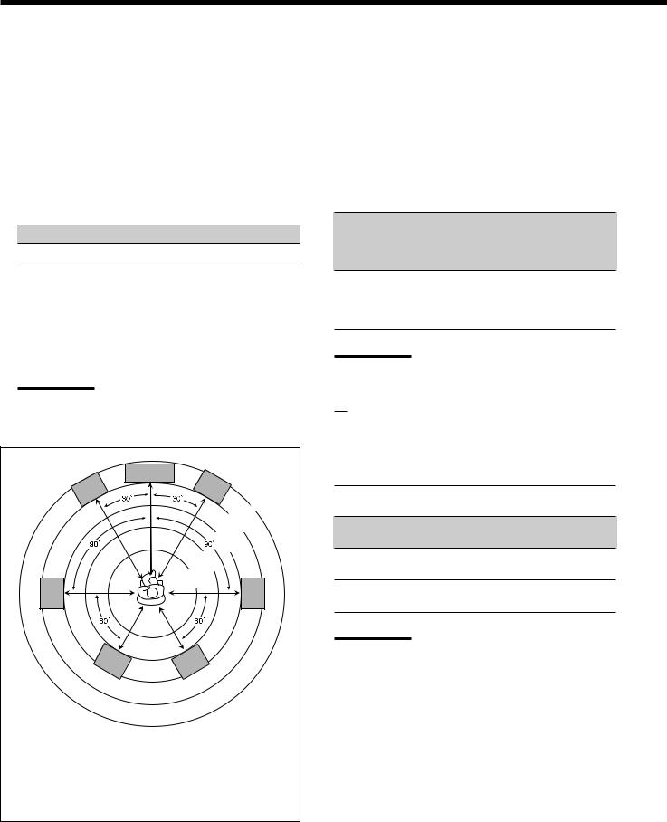
Setting the Speaker Distance
The distance from your listening point to the speakers is another important element to obtain the best possible sound of the Surround and DSP modes. Set the distance from your listening point to the speakers.
By referring to the speaker distance setting, this unit automatically sets the delay time of the sound through each speaker so that sounds through all the speakers can reach you at the same time.
•If you have used Quick Speaker Setup on page 25, this setting is not required.
7Measuring unit—DIST UNIT
Select which measuring unit you use. meter: Select to set the distance in meters. feet: Select to set the distance in feet.
7Speaker distance—FRONT DISTANCE, CNTR DISTANCE, SURR DISTANCE, SBACK DISTANCE
Set the distance from the listening point within the range of
0.3 m (1 ft) to 9.0 m (30 ft), in 0.3 m (1 ft) intervals.
•When shipped from the factory, distance for each speaker is set to “3.0 m (10 ft).”
Notes:
•You cannot set the speaker distance for the speakers you have selected “NONE” (see page 27).
•This setting is not valid for the DVD MULTI playback mode.
C
L |
R |
3.3 m
(11 ft)
3.0 m
(10 ft)
|
2.7 m |
|
(9 ft) |
|
2.4 m |
|
(8 ft) |
|
2.1 m |
|
(7 ft) |
LS |
RS |
LSB RSB
Ex. In the above case, set the speaker distance as follows:
Front speakers: |
3.0 m (10 ft) |
Center speakers: |
3.0 m (10 ft) |
Surround speakers: |
2.7 m (9 ft) |
Surround back speakers: |
2.4 m (8 ft) |
Setting the Bass Sounds
You can adjust subwoofer and bass sounds precisely according to your preference.
7Subwoofer output—S WFR OUTPUT
You can select the type of the signal which can be transmitted through the subwoofer. In other words, you can determine whether or not the bass elements of the front speaker channels are transmitted through the subwoofer regardless of the front speaker size setting (either “SMALL” or “LARGE”).
Select one of the following:
LFE: Select to transmit only the LFE signals (while playing Dolby Digital and DTS software) and the bass elements of small speakers through the subwoofer.
LFE+MAIN: Select to always add the bass elements of the front speaker channels (MAIN) to the above (LFE) setting, and to transmit them through the subwoofer.
Note:
If you have selected “NO” for the subwoofer, this function is not available.
7Crossover frequency—CROSS OVER
When you use a subwoofer, you can select the cutoff frequency for the small speakers used.
Select one of the crossover frequency levels according to the size of the small speaker connected.
80Hz: Select when the cone speaker unit built in the speaker is about 12 cm (4 3/4 inches).
100Hz: Select when the cone speaker unit built in the speaker is about 10 cm (3 15/16 inches).
120Hz: Select when the cone speaker unit built in the speaker is about 8 cm (3 3/16 inches).
150Hz: Select when the cone speaker unit built in the speaker is about 6 cm (2 3/8 inches).
Notes:
.• If you have selected “LARGE” for all activated speakers (see page 27), this function is fixed to “OFF.”
•Crossover frequency is not valid for the DVD MULTI playback,
All Channel Stereo, HEADPHONE, and 3D HEADPHONE mode.
28
Loading...