


 Loading...
AUDIO/VIDEO CONTROL RECEIVER
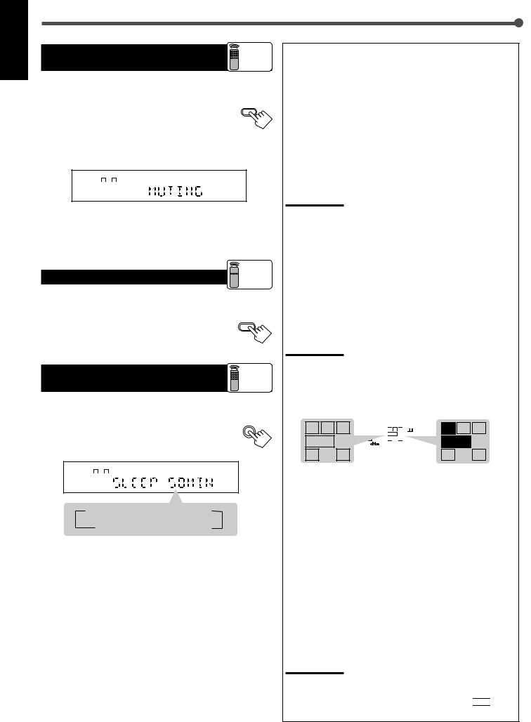
RX-6020VBK
|
|
|
RX-6020V AUDIO/VIDEO CONTROL RECEIVER |
|
|||
FM/AM TUNING |
FM/AM PRESET |
FM MODE |
|
|
|
|
|
STANDBY |
|
|
|
|
|
|
MASTER VOLUME |
|
|
MEMORY |
|
|
|
|
|
PTY–PTY SEARCH–PTY |
|
|
|
|
|
|
|
STANDBY/ON |
|
|
|
|
|
|
|
SURROUND ON/OFF |
INPUT ANALOG |
INPUT DIGITAL |
|
|
ADJUST |
SETTING |
|
|
|
|
DVD MULTI |
DVD |
VCR |
TV SOUND |
|
FM MODE |
INPUT ATT |
|
|
|
|
|
|
|
|
|
|
|
|
CONTROL |
|
SURROUND MODE |
SPEAKERS ON/OFF |
|
|
|
DOWN |
UP |
|
|
|
|
CD |
TAPE/CDR |
FM |
AM |
|
|
|
|
|
SOURCE NAME |
|
|
|
PHONES |
|
|
|
|
|
|
|
INSTRUCTIONS
For Customer Use:
Enter below the Model No. and Serial No. which are located either on the rear, bottom or side of the cabinet. Retain this information for future reference.
Model No.
Serial No.
LVT0851-001A
[J]
AUDIO/VIDEO CONTROL RECEIVER
RECEPTEUR DE CONTROL AUDIO/VIDEO
RX-6020VBK
|
|
|
RX-6020V AUDIO/VIDEO CONTROL RECEIVER |
|
|||
FM/AM TUNING |
FM/AM PRESET |
FM MODE |
|
|
|
|
|
STANDBY |
|
|
|
|
|
|
MASTER VOLUME |
PTY–PTY SEARCH–PTY |
|
MEMORY |
|
|
|
|
|
STANDBY/ON |
|
|
|
|
|
|
|
SURROUND ON/OFF |
INPUT ANALOG |
INPUT DIGITAL |
|
|
ADJUST |
SETTING |
|
FM MODE |
INPUT ATT |
|
DVD MULTI |
DVD |
VCR |
TV SOUND |
|
|
|
|
|
|
|
|
|
|
|
|
|
|
|
CONTROL |
|
SURROUND MODE |
SPEAKERS ON/OFF |
|
|
|
DOWN |
UP |
|
|
|
|
CD |
TAPE/CDR |
FM |
AM |
|
|
|
|
|
SOURCE NAME |
|
|
|
PHONES |
|
|
|
|
|
|
|
INSTRUCTIONS
MANUAL D’INSTRUCTIONS
For Customer Use:
Enter below the Model No. and Serial No. which are located either on the rear, bottom or side of the cabinet. Retain this information for future reference.
Model No.
Serial No.
LVT0851-002A
[C]
Warnings, Cautions and Others/
Mises en garde, précautions et indications diverses
|
|
CAUTION |
|
|
|
RISK OF ELECTRIC SHOCK |
|
|
|
DO NOT OPEN |
|
|
|
|
|
|
|
|
|
CAUTION: |
TO REDUCE THE RISK OF ELECTRIC SHOCK. |
||
|
DO NOT REMOVE COVER (OR BACK) |
||
|
NO USER SERVICEABLE PARTS INSIDE. |
||
REFER SERVICING TO QUALIFIED SERVICE PERSONNEL.
The lightning flash with arrowhead symbol, within an equilateral triangle is intended to alert the user to the presence of uninsulated "dangerous voltage" within the product's enclosure that may be of sufficient magnitude to constitute a risk of electric shock to persons.
The exclamation point within an equilateral triangle is intended to alert the user to the presence of important operating and maintenance (servicing) instructions in the literature accompanying the appliance.
WARNING: TO REDUCE THE RISK OF FIRE OR ELECTRIC SHOCK, DO NOT EXPOSE THIS APPLIANCE TO RAIN OR MOISTURE.
CAUTION
To reduce the risk of electrical shocks, fire, etc.:
1.Do not remove screws, covers or cabinet.
2.Do not expose this appliance to rain or moisture.
ATTENTION
Afin d’éviter tout risque d’électrocution, d’incendie, etc.:
1.Ne pas enlever les vis ni les panneaux et ne pas ouvrir le coffret de l’appareil.
2.Ne pas exposer l’appareil à la pluie ni à l’humidité.
Caution –– STANDBY/ON  button!
Disconnect the mains plug to shut the power off completely. The STANDBY/ON  button in any position does not disconnect the mains line. The power can be remote controlled.
Attention –– Commutateur STANDBY/ON  !
!
Déconnecter la fiche de secteur pour couper complètement le courant. Le commutateur STANDBY/ON  ne coupe jamais complètement la ligne de secteur, quelle que soit sa position. Le courant peut être télécommandé.
For Canada/pour le Canada
CAUTION: TO PREVENT ELECTRIC SHOCK, MATCH WIDE BLADE OF PLUG TO WIDE SLOT, FULLY INSERT
ATTENTION: POUR EVITER LES CHOCS ELECTRIQUES, INTRODUIRE LA LAME LA PLUS LARGE DE LA FICHE DANS LA BORNE CORRESPONDANTE DE LA PRISE ET POUSSER JUSQUAU FOND
For U.S.A.
This equipment has been tested and found to comply with the limits for a Class B digital device, pursuant to part 15 of the FCC Rules. These limits are designed to provide reasonable protection against harmful interference in a residential installation.
This equipment generates, uses and can radiate radio frequency energy and, if not installed and used in accordance with the instructions, may cause harmful interference to radio communications. However, there is no guarantee that interference will not occur in a particular installation. If this equipment does cause harmful interference to radio or television reception, which can be determined by turning the equipment off and on, the user is encouraged to try to correct the interference by one or more of the following measures:
Reorient or relocate the receiving antenna.
Increase the separation between the equipment and receiver. Connect the equipment into an outlet on a circuit different from that to which the receiver is connected.
Consult the dealer or an experienced radio/TV technician for help.
Changes or modifications not expressly approved by the manufacturer for compliance could void the user’s authority to operate the equipment.
For Canada/pour Le Canada
THIS DIGITAL APPARATUS DOES NOT EXCEED THE CLASS
B LIMITS FOR RADIO NOISE EMISSIONS FROM DIGITAL APPARATUS AS SET OUT IN THE INTERFERENCE-CAUSING
EQUIPMENT STANDARD ENTITLED “DIGITAL APPARATUS,”
ICES-003 OF THE DEPARTMENT OF COMMUNICATIONS. CET APPAREIL NUMERIQUE RESPECTE LES LIMITES DE
BRUITS RADIOELECTRIQUES APPLICABLES AUX
APPAREILS NUMERIQUES DE CLASSE B PRESCRITES DANS LA NORME SUR LE MATERIEL BROUILLEUR;
“APPAREILS NUMERIQUES”, NMB-003 EDICTEE PAR LE
MINISTRE DES COMMUNICATIONS.
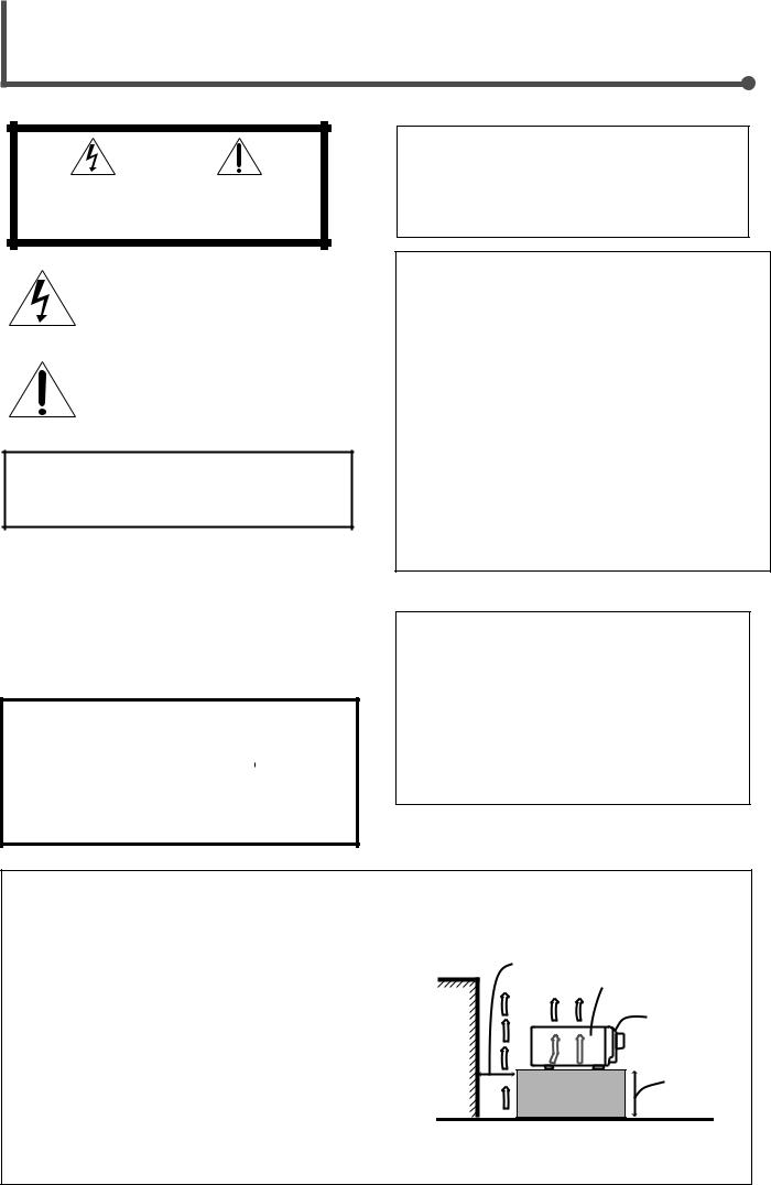
Caution: Proper Ventilation
To avoid risk of electric shock and fire and to protect from damage.
Locate the apparatus as follows:
Front: |
No obstructions open spacing. |
Sides: |
No obstructions in 10 cm from the sides. |
Top: |
No obstructions in 10 cm from the top. |
Back: |
No obstructions in 15 cm from the back. |
Bottom: |
No obstructions, place on the level surface. |
In addition, maintain the best possible air circulation as illustrated.
Attention: Ventilation Correcte
Wall or obstructions Mur, ou obstruction
Pour éviter les chocs électriques, l’incendie et tout autre dégât. Disposer l’appareil en tenant compte des impératifs suivants
Avant: |
Rien ne doit gêner le dégagement |
Flancs: |
Laisser 10 cm de dégagement latéral |
Dessus: |
Laisser 10 cm de dégagement supérieur |
Arrière: |
Laisser 15 cm de dégagement arrière |
Dessous: |
Rien ne doit obstruer par dessous; poser l’appareil sur une |
surface plate.
Veiller également à ce que l’air circule le mieux possible comme illustré.
Spacing 15 cm or more
Dégagement de 15 cm ou plus
RX-6020VBK
Front
Avant
Stand height 15 cm or more Hauteur du socle: 15 cm ou plus
Floor
Plancher

Table of Contents |
|
|
Parts Identification ...................................... |
2 |
|
Getting Started........................................... |
3 |
|
Before Installation ...................................................................... |
3 |
|
Checking the Supplied Accessories ........................................... |
3 |
|
Putting Batteries in the Remote Control .................................... |
3 |
|
Connecting the FM and AM Antennas ....................................... |
4 |
|
Connecting the Speakers ............................................................ |
5 |
|
Connecting Audio/Video Components ....................................... |
6 |
|
Connecting the Power Cord ....................................................... |
7 |
|
Basic Operations ......................................... |
8 |
|
Turning On the Power ................................................................ |
8 |
|
Selecting the Source to Play ....................................................... |
8 |
|
Adjusting the Volume ................................................................. |
9 |
|
Listening Only with Headphones ............................................... |
9 |
|
Turning Off the Sounds Temporarily—Muting ........................ |
10 |
|
Changing the Display Brightness ............................................. |
10 |
|
Turning Off the Power with the Sleep Timer ........................... |
10 |
|
Basic Settings ........................................... |
11 |
|
Setting the Digital Input (DIGITAL IN) Terminals ................. |
11 |
|
Selecting the Analog or Digital Input Mode ............................ |
11 |
|
Setting the Speaker Information ............................................... |
12 |
|
Sound Adjustments.................................... |
15 |
|
Attenuating the Input Signal .................................................... |
15 |
|
Adjusting the Front Speakers Output Balance ......................... |
15 |
|
Adjusting the Tone ................................................................... |
15 |
|
Adjusting the Subwoofer Output Level .................................... |
15 |
|
Tuner Operations ....................................... |
16 |
|
Tuning in Stations .................................................................... |
16 |
|
Using Preset Tuning ................................................................. |
16 |
|
Selecting the FM Reception Mode ........................................... |
17 |
|
Creating Realistic Sound Fields ................... |
18 |
|
About Relations between Speaker Layout and |
|
|
Surround Modes ................................................................. |
20 |
|
Using Dolby Pro Logic II, Dolby Digital and |
|
|
DTS Digital Surround ........................................................ |
21 |
|
Using DAP Modes and All Channel Stereo ............................. |
23 |
|
Using DVD MULTI Playback Mode ................ |
24 |
|
Activating DVD MULTI Playback Mode ................................ |
24 |
|
COMPU LINK Remote Control System ......... |
25 |
|
AV COMPU LINK Remote Control System .... |
26 |
|
Operating JVC's Audio/Video |
|
|
Components .......................................... |
28 |
|
Operating Audio Components .................................................. |
28 |
|
Operating Video Components .................................................. |
29 |
|
Troubleshooting ......................................... |
30 |
|
Specifications ............................................ |
31 |
|
|
This mark indicates that the remote control CAN |
|
Remote |
|
|
ONLY |
ONLY be used for the operation explained. |
|
|
This mark indicates that the remote control CANNOT |
|
Remote |
be used for the operation explained. Use buttons on |
|
NOT |
|
|
|
the front panel. |
|
English
1

Parts Identification
English
Front Panel
1 |
2 |
3 |
4 5 |
6 |
7 89 |
p |
|
|
|
|
RX-6020V |
AUDIO/VIDEO CONTROL RECEIVER |
|
||
FM/AM TUNING |
FM/AM PRESET |
FM MODE |
|
|
|
|
|
|
STANDBY |
|
|
ANALOG |
SPK |
|
TUNED STEREO AUTOMUTING SLEEP |
|
|
|
|
MEMORY |
DIGITAL AUTO |
L C R |
PROLOGIC ΙΙ DSP H.PHONE |
INPUT ATT |
VOLUME |
MASTER VOLUME |
|
|
LINEAR PCM |
S.WFR LFE |
|
|
|
||
|
|
|
DIGITAL |
LS S RS |
|
|
|
|
STANDBY/ON |
|
|
|
CH- |
|
|
|
|
SURROUND ON/OFF |
INPUT ANALOG |
INPUT DIGITAL |
|
|
|
ADJUST |
SETTING |
|
|
|
|
|
|||||
|
|
|
|
DVD MULTI |
DVD |
VCR |
TV SOUND |
|
|
INPUT ATT |
|
|
|
|
|
|
|
|
|
|
|
|
|
|
CONTROL |
|
SURROUND MODE |
SPEAKERS ON/OFF |
|
|
|
|
DOWN |
UP |
|
|
|
|
|
|
|
CD |
TAPE/CDR |
FM |
AM |
|
|
|
|
|
|
|
|
SOURCE NAME |
|
|
|
PHONES |
|
|
|
|
|
|
|
|
|
|
q |
w e |
r t y |
u |
i |
|
o |
|
|||
|
Remote Control |
|
|
See page(s) in the parentheses for details. |
||||||
|
|
|
Front Panel |
|
||||||
|
|
|
|
|
|
|
|
|
||
|
|
|
|
|
|
|
|
1 |
STANDBY/ON button and STANDBY lamp (8) |
|
|
|
|
|
|
|
|
|
2 |
FM/AM TUNING 5/∞ (up/down) buttons (16) |
|
|
|
|
|
|
|
|
|
3 |
FM/AM PRESET 5/∞ (up/down) buttons (16, 17) |
|
|
|
|
|
|
|
|
|
4 |
FM MODE button (17) |
|
|
|
|
|
|
|
|
|
5 |
MEMORY button (16, 17) |
|
|
|
|
A/V CONTROL |
STANDBY/ON |
|
|
6 |
Display (8) |
|
|
|
|
|
RECEIVER |
|
|
|
7 |
ADJUST button (15, 22, 23, 24) |
||
|
TEST |
|
CENTER |
AUDIO |
|
|
8 |
Remote sensor (3) |
|
|
|
1 |
|
2 |
3 |
|
|
|
9 |
SETTING button (11 – 14) |
|
|
EFFECT |
|
REAR L |
TV |
|
|
p MASTER VOLUME control (9) |
|||
|
|
|
|
q PHONES jack (9) |
|
|||||
|
|
|
|
|
q |
|
|
|||
|
4 |
|
5 |
6 |
|
|
|
|||
1 |
MENU |
|
REAR R |
VCR |
|
|
w SURROUND ON/OFF button (20 – 23) |
|||
|
|
|
|
|
|
|
e SURROUND MODE button (20 – 23) |
|||
|
7/P |
|
8 |
9 |
|
|
|
|||
|
|
|
|
|
r SPEAKERS ON/OFF button (9) |
|||||
|
ENTER |
|
SUBWOOFER |
|
|
|
||||
|
|
DVD |
|
|
t • INPUT ANALOG button (11) |
|||||
|
10 |
|
0 |
10 |
|
|
||||
|
|
|
|
|
|
• INPUT ATT button (15) |
||||
|
RETURN |
|
|
100 |
SLEEP |
|
|
y INPUT DIGITAL button (11, 12) |
||
2 |
SOUND |
|
w |
|
||||||
|
|
|
u SOURCE NAME button (9) |
|||||||
|
|
|
|
|
|
|||||
|
REW |
|
|
FF |
|
|
i Source selecting buttons (8, 9, 11, 16, 17, 24) |
|||
3 |
|
|
|
|
|
|
|
|
DVD MULTI, DVD, VCR, TV SOUND, CD, TAPE/CDR, FM, AM |
|
|
REC PAUSE |
|
|
CD–DISC |
|
|
o CONTROL UP5/DOWN∞ buttons (11 – 15, 22 – 24) |
|||
4 |
|
|
|
|
|
e |
|
Remote Control |
|
|
|
TAPE/CDR |
|
CD |
DVD |
DVD MULTI |
|
|
1 |
• 10 keys for selecting preset channels (17) |
|
|
|
|
|
|
|
|
|
|||
5 |
FM/AM |
TV SOUND |
VCR |
ANALOG |
|
|
|
• 10 keys for adjusting sound (15, 22, 23, 24) |
||
|
/DIGITAL |
r |
|
|
• 10 keys for operating audio/video components (28, 29) |
|||||
|
|
|
|
|
|
|
|
|||
|
|
|
|
|
|
|
2 |
SOUND button (15, 22 – 24) |
||
|
|
|
|
|
|
|
|
|||
6 |
FM MODE |
|
|
|
|
|
|
3 |
Operating buttons for audio/video components |
|
|
|
|
ON/OFF |
|
t |
|
|
(25, 28, 29) |
|
|
|
|
|
|
|
|
|
|
|
||
7 |
DIMMER |
TV/VIDEO SURROUND |
MUTING |
y |
|
4 |
REC PAUSE button (28, 29) |
|||
|
|
|
MODE |
|
|
5 |
Source selecting buttons (8, 9, 11, 17, 24, 27 – 29) |
|||
8 |
|
|
|
|
|
u |
|
|
TAPE/CDR, CD, DVD, DVD MULTI, FM/AM, TV SOUND, VCR |
|
|
|
|
|
|
|
|
|
6 |
FM MODE button (17) |
|
9 |
VCR CH |
|
TV CH |
TV VOLUME |
i |
|
7 |
DIMMER button (10) |
||
|
|
|
|
|
|
|
|
8 |
TV/VIDEO button (29) |
|
p |
|
|
|
|
VOLUME |
|
|
9 |
VCR CH (channel) +/– buttons (29) |
|
|
|
|
|
|
|
p TV CH (channel) +/– buttons (29) |
||||
|
|
|
|
|
|
|
||||
|
REMOTE CONTROL RMSRX6020J |
|
|
q STANDBY/ON |
buttons (8, 26, 29) |
|||||
|
|
|
|
AUDIO, TV, VCR, DVD |
||||||
|
|
|
|
|
|
|
|
|
||
|
|
|
|
|
|
|
|
w SLEEP button (10) |
|
|
|
|
|
|
|
|
|
|
e CD–DISC button (28) |
||
|
|
|
|
|
|
|
|
r ANALOG/DIGITAL button (12) |
||
|
|
|
|
|
|
|
|
t SURROUND ON/OFF and SURROUND MODE buttons |
||
|
|
|
|
|
|
|
|
|
(20, 21, 23, 28) |
|
|
|
|
|
|
|
|
|
y MUTING button (10) |
||
|
|
|
|
|
|
|
|
u TV VOLUME +/– buttons (29) |
||
|
|
|
|
|
|
|
|
i VOLUME +/– button (9) |
||
2 |
|
|
|
|
|
|
|
|
|
|
Getting Started
Before Installation |
Putting Batteries in the Remote Control |
General Precautions
•DO NOT insert any metal object to the unit.
•DO NOT disassemble the unit or remove screws, covers, or cabinet.
•DO NOT expose the unit to rain or moisture.
Locations
•Install the unit in a location that is level and protected from moisture.
•The temperature around the unit must be between –5˚C and 35˚C (23˚F and 95˚F).
•Make sure there is good ventilation around the unit. Poor ventilation could cause overheating and damage the unit.
Handling the unit
•DO NOT touch the power cord with wet hands.
•DO NOT pull the power cord to unplug the cord. When unplugging the cord, always grasp the plug so as not to damage the cord.
•Keep the power cord away from the connecting cords and the antenna. The power cord may cause noise or screen interference. It is recommended to use a coaxial cable for antenna connection, since it is well-shielded against interference.
•When a power failure occurs, or when you unplug the power cord, the preset settings such as preset FM/AM channels and sound adjustments may be erased in a few days.
Checking the Supplied Accessories
Check to be sure you have all of the following supplied accessories. The number in the parentheses indicates the quantity of the piece(s) supplied.
•Remote Control (1)
•Batteries (2)
•AM Loop Antenna (1)
•FM Antenna (1)
If anything is missing, contact your dealer immediately.
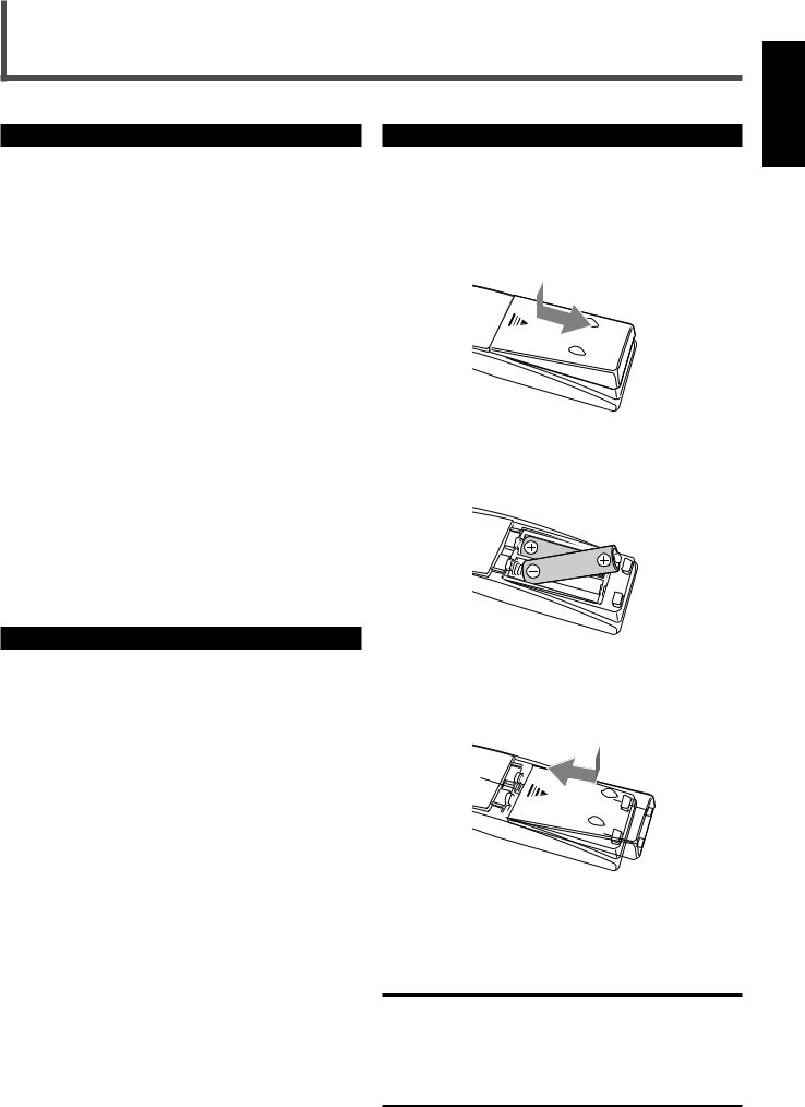
Before using the remote control, put two supplied batteries first.
•When using the remote control, aim the remote control directly at the remote sensor on the unit.
1On the back of the remote control, remove the battery cover.
2Insert batteries.
• Make sure to match the polarity: (+) to (+) and (–) to (–).
3 Replace the cover.
If the range or effectiveness of the remote control decreases, replace the batteries. Use two R6P(SUM-3)/AA(15F) type dry-cell batteries.
CAUTION:
Follow these precautions to avoid leaking or cracking cells:
•Place batteries in the remote control so they match the polarity:
(+) to (+) and (–) to (–).
•Use the correct type of batteries. Batteries that look similar may differ in voltage.
•Always replace both batteries at the same time.
•Do not expose batteries to heat or flame.
English
3
English
Getting Started
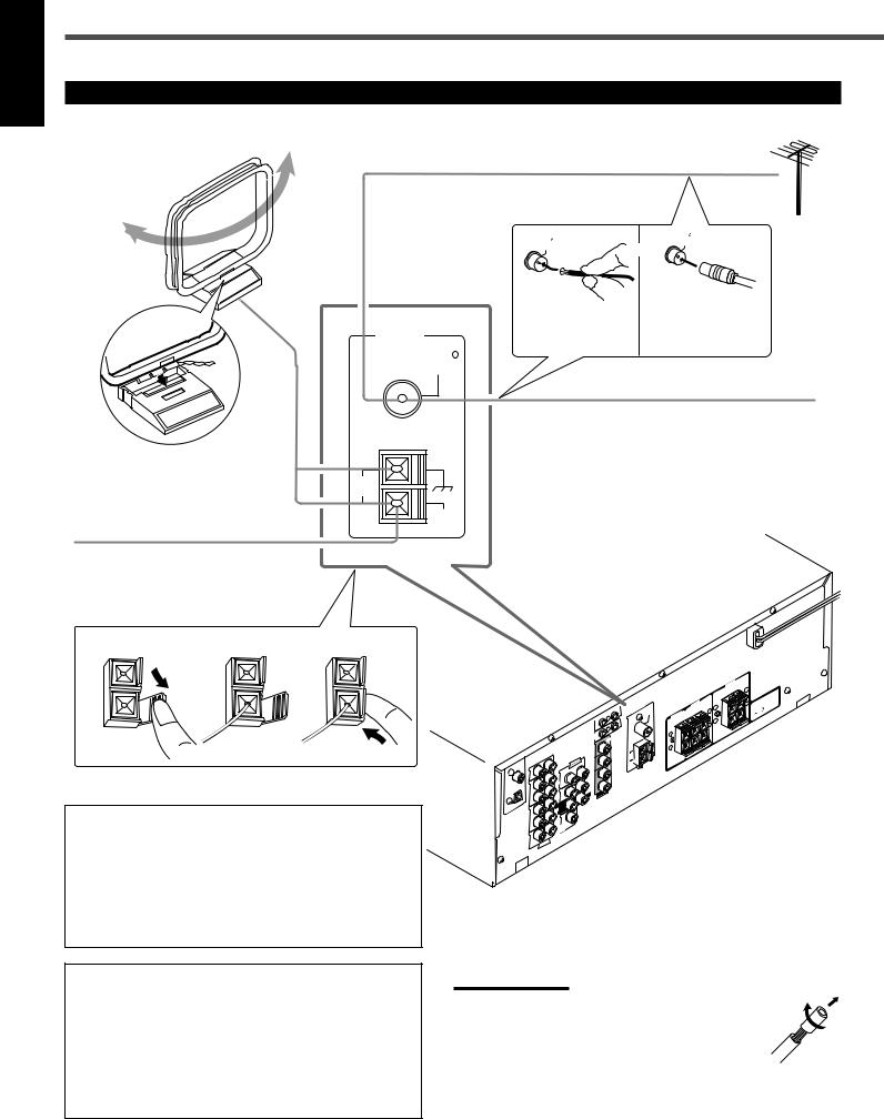
Connecting the FM and AM Antennas
AM Loop Antenna
(supplied) Outdoor FM antenna (not supplied)
If FM reception is poor, connect outdoor FM antenna.
75 |
or |
FM |
|
COAXIAL |
|
75 FMCOAXIAL
Snap the tabs on the loop into the slots of the base to assemble the AM loop antenna.
If AM reception is poor, connect outdoor single vinyl-covered wire (not supplied).
ANTENNA
FM 75
COAXIAL
AM
LOOP
AM
EXT
Supplied FM |
Standard type |
outdoor FM antenna |
|
antenna |
(not supplied) |
FM antenna (supplied)
Extend the supplied FM antenna horizontally.
1 |
2 |
3 |
AM loop antenna connection
Connect the AM loop antenna supplied to the AM LOOP terminals.
Turn the loop until you have the best reception.
•If the reception is poor, connect an outdoor single vinylcovered wire (not supplied) to the AM EXT terminal. (Keep the AM loop antenna connected.)
|
1 |
|
|
|
) |
|
|
DIGITAL(DVD |
|
|
|
|
|
CD |
|
|
) |
OUT |
|
2 |
( CD |
|
|
|
(REC) |
|
|
DIGITAL |
|
TAPE |
|
|
|
/CDR |
|
|
|
IN |
|
|
IN |
(PLAY) |
|
|
|
|
|
DIGITAL |
OUT |
|
|
|
|
(REC) |
|
|
|
VCR |
|
|
|
IN |
|
|
|
(PLAY) |
|
|
|
|
LEFT |
|
TV |
SOUND |
RIGHT |
|
|
|
AUDIO |
|
AV LINK |
|
|
COMPU LINK |
|
|
-4 |
|
|
(SYNCHRO) |
MONITOR |
|
COMPU |
OUT |
|
|
DVD |
|
AUDIOLEFT |
OUT |
|
|
|
|
RIGHT |
(REC) |
|
DVD |
VCR |
|
|
|
FRONT |
CENTER |
IN |
(PLAY) |
||
SUB |
LEFT |
VIDEO |
WOOFER |
|
|
REAR |
|
|
RIGHT |
|
|
SUBWOOFEROUT |
|
|
ANTENNAFM 75
COAXIAL
AM
LOOP
REAR
SPEAKERS
CENTER
SPEAKER
+ –
FRONT
SPEAKERSLEFT
+ |
+ |
|
|
– |
– |
|
+ –
|
: |
IMPEDANCE |
CAUTION |
|
|
SPEAKER |
|
|
FM antenna connection
Connect the supplied FM antenna to the FM 75 Ω COAXIAL terminal as temporary measure.
Extend the supplied FM antenna horizontally.
•If the reception is poor, connect an outdoor FM antenna (not supplied). Before attaching a 75 Ω coaxial cable (with a standard type connector), disconnect the supplied FM antenna.
Notes:
•If the AM loop antenna wire is covered with vinyl, remove the vinyl while twisting it as shown to the right.
•Make sure antenna conductors do not touch any other terminals, connecting cords and the power cord. This could cause poor reception.
4
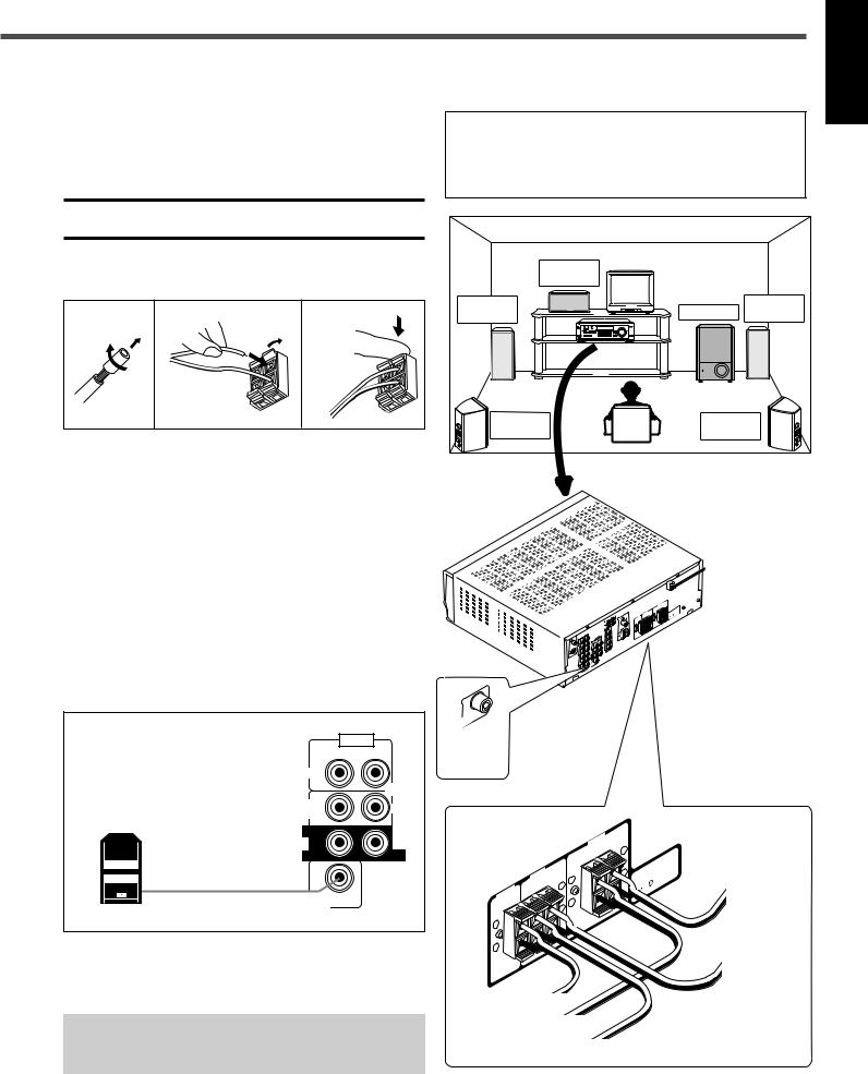
Connecting the Speakers |
Speaker layout diagram |
After connecting the front, center, rear speakers and/or a subwoofer, set the speaker setting information properly to obtain the best possible surround effect. For details, see pages 12 to 14.
CAUTION:
Use speakers with the SPEAKER IMPEDANCE indicated by the speaker terminals.
Connecting the front, center and rear speakers
1 |
2 |
3 |
1
2
For each speaker, connect the (+) and (–) terminals on the rear panel to the (+) and (–) terminals marked on the speakers.
1Cut, twist and remove the insulation at the end of each speaker cord.
2Open the terminal (1), then insert the speaker cord (2).
3Close the terminal.
Connecting the subwoofer speaker
By connecting a powered subwoofer, you can enhance the bass or reproduce the original LFE signals recorded in the digital software.
“NO” for the subwoofer, “LARGE” for the front speakers, and “SMALL” for the center and rear speakers are initial settings. To get best possible sound, change the subwoofer and speaker settings to fit your listening conditions (See pages 12 and 13).
|
Center |
|
speaker |
Left front |
Right front |
speaker |
Subwoofer speaker |
Left rear |
Right rear |
speaker |
speaker |
|
|
|
|
NT |
|
|
|
|
|
|
|
|
FRO ERS |
+ |
|
|
|
|
|
REAKERR S |
|
SPEAK |
|
|
|
|
NA |
|
|
+ |
– |
CAUTION |
: |
IMPEDANCE |
|
ANTEN |
|
SPEA |
+ |
|
|
SPEAKER16 |
|
|
CENTERR |
|
|
|
|
8 |
|
|
|
SP |
EAKE |
|
– |
– |
|
|
|
|
+ |
|
|
|
|
|
|
|
|
– |
|
|
|
|
|
|
|
|
|
|
L 1 |
|
|
DIGIT(DAVD) |
|
|||
|
|
|
|
CD |
|
2 ( CD |
) |
|
|
ITAL |
|
TAPE |
||
DIG |
|
|
|
/CDR |
DIGITAL |
IN |
|
|
|
|
|
|
||
|
|
|
|
VCR |
|
|
|
SUBWOOFEROUT |
AUDIO |
|
To |
|
RIGHT |
LEFT |
|
subwoofer |
|
|
|
|
FRONT |
|
|
|
|
|
DVD |
|
SUB |
|
CENTER |
|
WOOFER |
|
|
|
|
|
|
|
Powered subwoofer |
|
|
|
REAR |
|
|
|
|
|
|
FRONT |
RIGHT |
|
LEFT |
SPEAKERS |
|
|
|
REAR |
|
|
|
SPEAKERS |
SUBWOOFER |
|
|
CENTER |
|
|
SPEAKER |
|
OUT |
|
|
|
|
|
|
|
|
|
|
+ |
Connect the input jack of a powered subwoofer to the SUBWOOFER OUT jack on the rear panel, using a cable with RCA pin plugs (not supplied).
• Refer also to the manual supplied with your subwoofer.
Since bass sound is non-directional, you can place a powered subwoofer wherever you like. Normally place it in front of you.
–
To center speaker
To right front speaker
To right rear speaker
+
To left
front speaker
To left
rear speaker
English
5
English
Getting Started
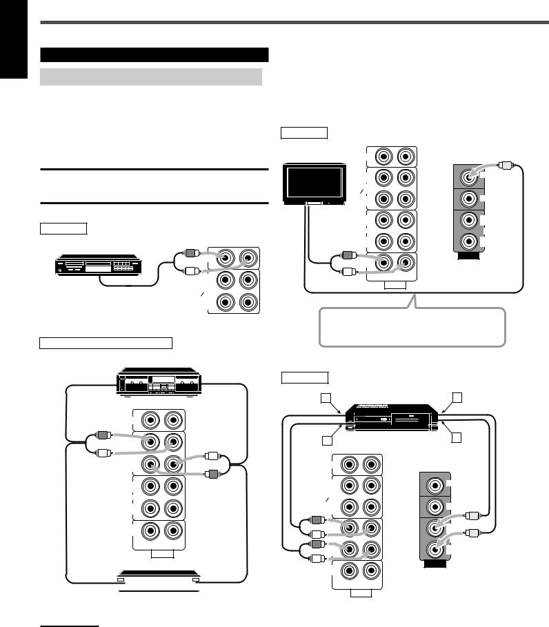
Connecting Audio/Video Components
Turn off all components before connecting.
Analog connections
Audio component connections
Use the cables with RCA pin plugs (not supplied).
Connect the white plug to the audio left jack, and the red plug to the audio right jack.
CAUTION:
If you connect a sound-enhancing device such as a graphic equalizer between the source components and this receiver, the sound output through this receiver may be distorted.
CD player
CD player
CD
OUT (REC)
To audio output |
TAPE |
CDR |
IN (PLAY)
Cassette deck or CD recorder |
|
|
|
Cassette deck |
|
To audio input |
PHONO |
To audio output |
|
CD |
|
Video component connections
Use the cables with RCA pin plugs (not supplied).
Connect the white plug to the audio left jack, the red plug to the audio right jack, and the yellow plug to the video jack.
TV
TV |
CD |
|
|
OUT |
MONITOR |
|
(REC) |
OUT |
|
TAPE |
|
|
CDR |
|
|
IN |
DVD |
To audio |
(PLAY) |
|
|
|
|
output |
OUT |
OUT |
|
(REC) |
(REC) |
|
VCR |
VCR |
|
IN |
IN |
|
(PLAY) |
(PLAY) |
|
TV SOUND |
VIDEO |
|
|
|
|
|
RIGHT |
|
|
AUDIO |
To video input
Connect the TV to the MONITOR OUT jack to view the playback picture from the other connected video components.
VCR
A |
VCR |
C |
CD
OUT (REC)
TAPE  CDR
CDR
IN (PLAY)
OUT (REC)
VCR
IN (PLAY)
TV SOUND
RIGHT LEFT
AUDIO
To audio input |
|
|
|
|
To audio output |
|
|
|
|
||
|
|
|
|
CD recorder
Note:
You can connect either a cassette deck or a CD recorder to the TAPE/
CDR jacks. When connecting a CD recorder to the TAPE/CDR jacks, change the source name to “CDR”, which will be shown on the display when selected as the source. See page 9 for details.
If your audio components have a COMPU LINK jack
See also page 25 for detailed information about the connection and the COMPU LINK remote control system.
B |
D |
|
CD |
|
|
OUT |
MONITOR |
|
(REC) |
OUT |
|
TAPE |
||
|
||
CDR |
|
|
IN |
DVD |
|
(PLAY) |
|
|
OUT |
OUT |
|
(REC) |
(REC) |
|
VCR |
VCR |
|
IN |
IN |
|
(PLAY) |
(PLAY) |
|
TV SOUND |
VIDEO |
|
|
||
RIGHT |
LEFT |
AUDIO
Å To left/right channel audio output ı To left/right channel audio input Ç To video output
Î To video input
6
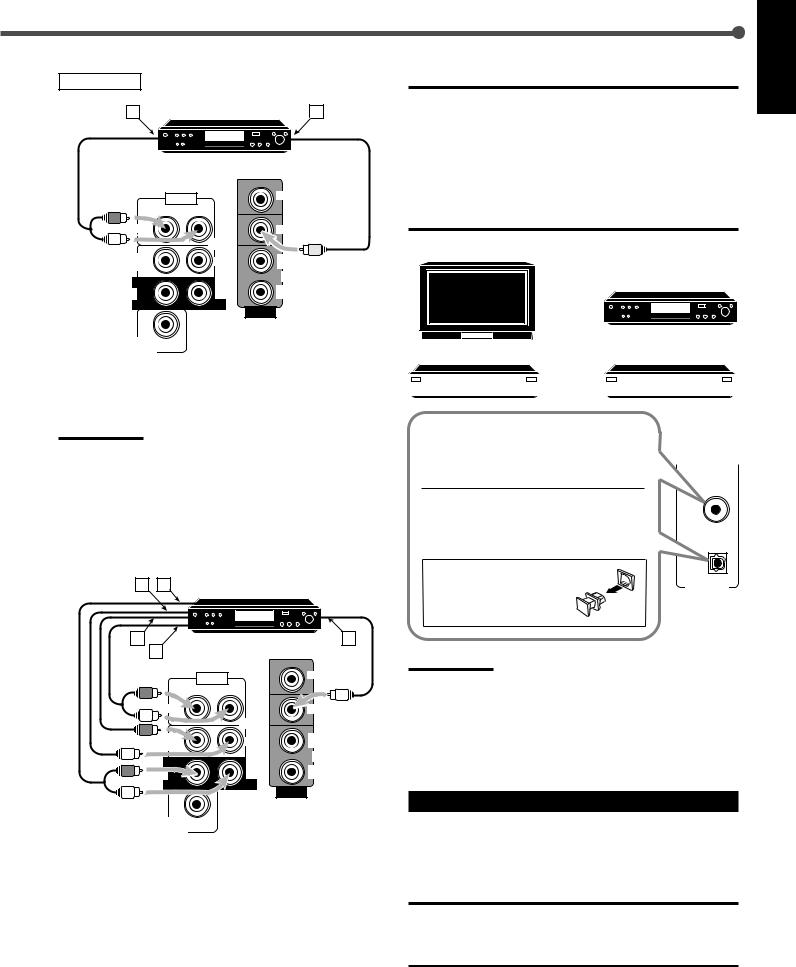
DVD player
A |
DVD player |
B |
DVD |
AUDIO |
MONITOR |
|
OUT |
||
|
RIGHT |
LEFT |
|
|
FRONT |
|
|
|
|
DVD |
|
|
SUB |
CENTER |
OUT |
|
WOOFER |
(REC) |
||
|
|||
REAR |
|
VCR |
|
|
IN |
||
|
|
||
|
|
(PLAY) |
|
RIGHT |
LEFT |
|
VIDEO
SUBWOOFER
OUT
Å To front left/right channel audio output (or to audio mixed output)
ı To video output
Note:
To enjoy the software encoded with Dolby Digital or DTS Digital Surround, you must connect the DVD player using the digital terminal on the rear of this receiver. (See “Digital connections” below.)
For enjoying DVD MULTI Playback Mode—
•When you connect the DVD player with its analog discrete output (5.1 CH reproduction) jacks:
B |
A |
DVD player |
|
|
DVD |
C |
|
|
E |
D |
|
|
|
AUDIO |
|
MONITOR |
|
|
|
||
RIGHT |
LEFT |
|
|
FRONT |
|
|
|
|
|
DVD |
|
SUB |
|
CENTER |
OUT |
WOOFER |
|
(REC) |
|
|
|
||
REAR |
|
|
VCR |
|
|
IN |
|
|
|
|
|
|
|
|
(PLAY) |
RIGHT |
|
LEFT |
|
VIDEO
SUBWOOFER
OUT
Å To rear left/right channel audio output ı To center channel audio output
Ç To subwoofer audio output
Î To front left/right channel audio output ‰ To video output
Digital connections
This receiver is equipped with two DIGITAL IN terminals—one digital coaxial terminal and one digital optical terminal.
You can connect any component to one of the digital terminals using a digital coaxial cable (not supplied) or digital optical cable (not supplied).
IMPORTANT:
•When connecting the DVD player or digital TV to the digital terminal, you also need to connect it to the video jack on the rear. Without connecting it to the video jack, you cannot view any playback picture.
•After connecting the components to the DIGITAL IN terminals, make sure the following if necessary:
–Set the digital input terminal setting correctly. For details, see “Setting the Digital Input (DIGITAL IN) Terminals” on page 11.
–Select the digital input mode correctly. For details, see “Selecting the Analog or Digital Input Mode” on page 11.
Digital TV
DVD player
DVD |
|
|
|
|
|
|
|
|
|
|
|
|
|
|
|
|
CD player |
|
|
CD recorder |
||||||||
|
|
|
|
|
|
|
|
|
|
|
|
|
|
|
|
|
|
|
|
|
|
|
|
|
|
|
|
When the component has a digital coaxial output terminal, connect it to the DIGITAL 1 (DVD) terminal, with the digital coaxial
cable (not supplied).
DIGITAL 1 (DVD)
When the component has a digital optical output terminal, connect it to the DIGITAL 2 (CD) terminal, with the digital optical
cable (not supplied). |
( CD ) |
|
|
||
Before connecting a digital |
IN |
|
optical cable, unplug the |
||
|
||
protective plug. |
|
Notes:
•When shipped from the factory, the DIGITAL IN terminals have been set for use with the following components:
–DIGITAL 1 (coaxial): For DVD player
–DIGITAL 2 (optical): For CD player
•When you want to operate the CD player or CD recorder using the COMPU LINK remote control system, connect the target component also as described in “Analog connections” (see page 6).
Connecting the Power Cord
Before plugging the power cord into an AC outlet, make sure that all connections have been made.
Plug the power cord into an AC outlet.
CAUTIONS:
•Do not touch the power cord with wet hands.
•Do not pull on the power cord to unplug the cord. When unplugging the cord, always grasp the plug so as not to damage the cord.
7
English
Basic Operations
English
Front Panel |
Remote Control |
STANDBY lamp |
Display |
|
|
|
|
|||
|
|
|
|
RX-6020V |
AUDIO/VIDEO CONTROL RECEIVER |
|
||
FM/AM TUNING |
FM/AM PRESET FM MODE |
|
|
|
|
|
|
|
STANDBY |
|
|
|
ANALOG SPK |
LOGIC ΙΙ DSP |
TUNED STEREO AUTOMUTING SLEEP |
|
|
|
|
MEMORY |
|
DIGITAL AUTO L C |
H.PHONE INPUT ATT |
VOLUME |
MASTER VOLUME |
|
|
|
|
LINEAR PCM S.WFR LFE |
|
|
|
||
|
|
|
|
LS S RS |
|
|
|
|
STANDBY/ON |
|
|
|
CH- |
|
|
|
|
SURROUND ON/OFF |
INPUT ATT |
|
|
|
|
|
Source |
|
INPUT ANALOG |
INPUT DIGITAL |
|
|
|
ADJUST SETTING |
|
||
|
|
|
|
DVD MULTI |
DVD |
VCR |
TV SOUND |
|
SURROUND MODE |
SPEAKERS ON/OFF |
|
|
|
|
DOWN UP |
selecting |
|
|
|
|
|
|
|
|
CONTROL |
|
|
|
|
|
CD |
TAPE/CDR |
FM |
AM |
buttons |
|
|
|
|
|
SOURCE NAME |
|
||
PHONES |
|
|
|
|
|
|
|
DIMMER |
|
|
|
|
|
|
|
|
|
PHONES |
SPEAKERS |
SOURCE |
Source |
MASTER |
||||
jack |
ON/OFF |
|
selecting |
VOLUME |
||||
|
|
|
|
NAME |
|
buttons |
|
|
STANDBY/ON |
|
|
|
|
|
|||
|
|
|
|
|
|
|
||
|
|
A/V CONTROL |
STANDBY/ON |
|
|
|
RECEIVER |
|
|
TEST |
|
CENTER |
AUDIO |
|
1 |
|
2 |
3 |
|
EFFECT |
|
REAR L |
TV |
|
4 |
|
5 |
6 |
|
MENU |
|
REAR R |
VCR |
|
7/P |
|
8 |
9 |
|
ENTER |
|
SUBWOOFER |
DVD |
|
10 |
|
0 |
10 |
|
RETURN |
|
|
100 |
SLEEP |
SOUND |
|
|
||
REW |
|
|
FF |
|
REC PAUSE |
|
|
CD–DISC |
|
TAPE/CDR |
|
CD |
DVD |
DVD MULTI |
|
|
|
|
ANALOG |
FM/AM |
TV SOUND |
VCR |
/DIGITAL |
|
FM MODE |
|
|
|
|
|
|
|
ON/OFF |
|
DIMMER |
TV/VIDEO SURROUND |
MUTING |
||
|
|
|
MODE |
|
VCR CH |
|
TV CH |
TV VOLUME |
|
|
|
|
|
VOLUME |
REMOTE CONTROL RM -SRX6020J
STANDBY/ ON  AUDIO
AUDIO
SLEEP
MUTING
VOLUME +/–
Turning On the Power
Press STANDBY/ON  (or STANDBY/ON
  AUDIO on the remote control).
|
STANDBY/ON |
STANDBY |
|
|
AUDIO |
STANDBY/ON |
|
On the front panel |
From the remote control |
The STANDBY lamp goes off. The name of the current source (or station frequency) appears on the display.
Current source name appears
ANALOG SPK |
|
|
L C |
R |
VOLUME |
S.WFR LFE |
|
|
LS S |
RS |
|
|
CH- |
|
|
Current volume level is shown here |
|
To turn off the power (into standby mode) |
||
|
|
STANDBY |
Press STANDBY/ON |
(or |
|
STANDBY/ON |
AUDIO on the remote control) |
|
STANDBY/ON
again.
The STANDBY lamp lights up.
NOTE:
A small amount of power is consumed in standby mode. To turn the power off completely, unplug the AC power cord.
Selecting the Source to Play
Press one of the source selecting buttons.
The selected source name appears on the display.
DVD MULTI |
DVD |
VCR |
TV SOUND |
TAPE/CDR |
CD |
DVD |
DVD MULTI |
CD |
TAPE/CDR |
FM |
AM |
FM/AM |
TV SOUND |
VCR |
|
|
|
|
|
||||
|
SOURCE NAME |
|
|
|
|
|
|
On the front panel From the remote control
DVD MULTI : Select the DVD player for viewing the digital video
|
disc using the analog discrete output mode (5.1 ch |
|
reproduction). |
|
To enjoy the DVD MULTI playback, see page 24. |
DVD |
: Select the DVD player. |
VCR |
: Select the VCR. |
TV SOUND |
: Select the TV sound. |
CD * |
: Select the CD player. |
TAPE/CDR * |
: Select the cassette deck (or the CD recorder). |
FM and AM (FM/AM) *
:Select an FM or AM broadcast.
•Each time you press FM/AM on the remote control, the band alternates between FM and AM.
Notes:
•When connecting a CD recorder (to the TAPE/CDR jacks), change the source name that appears on the display. See page 9 for details.
•When you have connected some digital source components using digital terminals (see page 7), you need to select the digital input mode (see page 11).
•When you press one of the source selecting buttons on the remote control marked above with an asterisk (*), the receiver automatically turns on.
8
Changing the source name
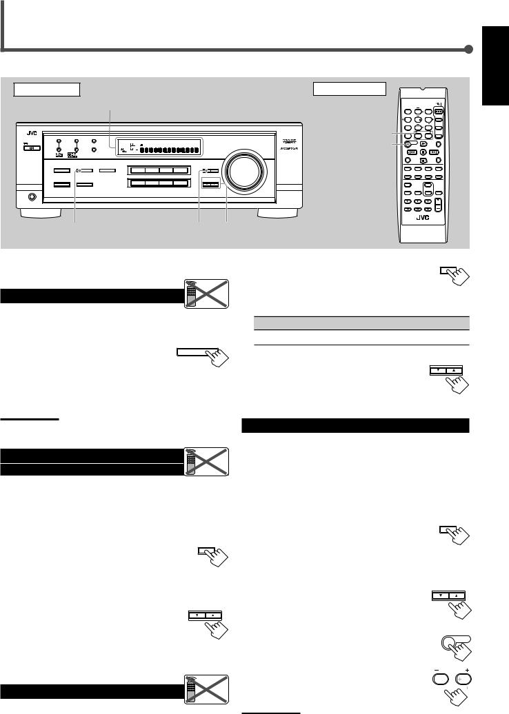
When you connect the CD recorder to the TAPE/CDR jacks on the rear panel, change the source name shown on the display.
1Press TAPE/CDR (SOURCE NAME).
• Make sure “TAPE” appears on the display.
2Press and hold SOURCE NAME (TAPE/CDR) until “ASSIGN CDR” appears on the display.

 Remote
NOT
TAPE/CDR
SOURCE NAME
To change the source name from “CDR” to “TAPE,” repeat the same procedure above (in step 1, make sure “CDR” appears on the display).
Note:
Without changing the source name, you can still use the connected component. However, there may be some inconvenience:
–“TAPE” will appear on the display when you select the CD recorder.
–You cannot use the digital input (see page 11) for the CD recorder.
–You cannot use the COMPU LINK remote control system (see page 25) to operate the CD recorder.
Selecting different sources for each picture and sound
You can watch picture from a video component while listening to sound from another component.
Press one of the audio source selecting buttons—CD, TAPE/CDR, FM, AM (FM/AM), while viewing the picture from a video component such as the VCR or DVD player, etc.
|
|
|
TAPE/CDR |
CD |
DVD |
DVD MULTI |
CD |
TAPE/CDR |
FM |
AM |
TV SOUND |
VCR |
|
|
|
|
FM/AM |
|
SOURCE NAME
On the front panel From the remote control
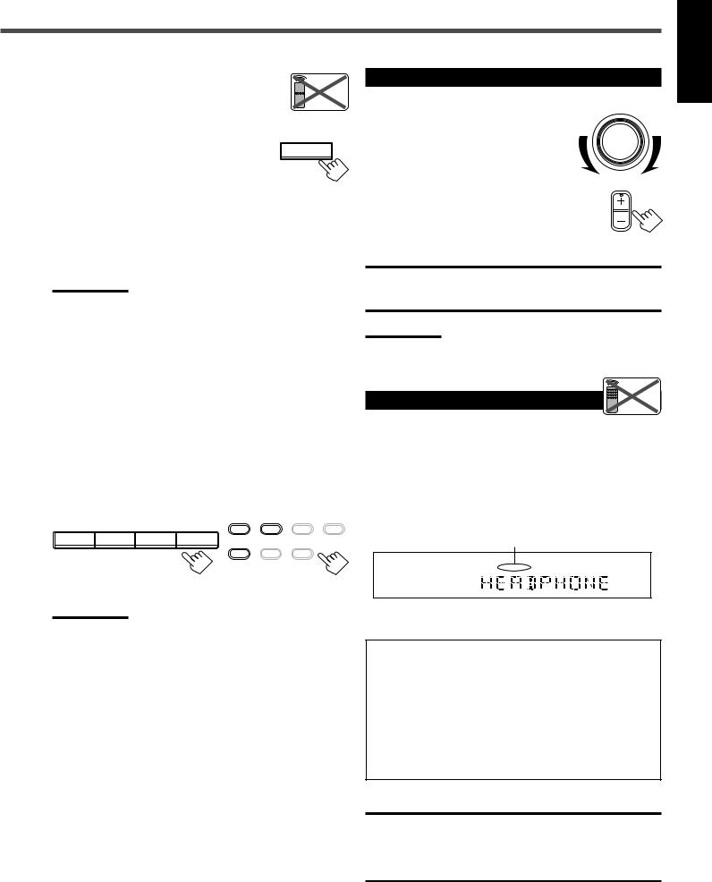
Adjusting the Volume
On the front panel: |
MASTER VOLUME |
To increase the volume, turn MASTER VOLUME clockwise.
To decrease the volume, turn it counterclockwise.
From the remote control:
To increase the volume, press VOLUME +.
To decrease the volume, press VOLUME –.
VOLUME
CAUTION:
Always set the volume to the minimum before starting any source. If the volume is set at its high level, the sudden blast of sound energy can permanently damage your hearing and/or ruin your speakers.
Note:
The volume level can be adjusted within the range from “0” (minimum) to “50” (maximum).
Listening Only with Headphones |
Remote |
NOT |
You must turn off speakers when you listen with headphones.
1Connect a pair of headphones to the PHONES jack on the front panel.
2Press SPEAKERS ON/OFF.
•“HEADPHONE” appears for a while and the H. PHONE indicator lights up on the display.
The H. PHONE indicator lights up.
ANALOG
L |
R |
H.PHONE |
Note:
Once you have selected a video source, pictures of the selected source are sent to the TV until you select another video source.
This cancels the Surround mode currently selected, and activates the HEADPHONE mode (see below).
HEADPHONE mode:
When using the headphones, following signals are output regardless of your speaker setting:
—For 2 channel sources, the front left and right channel signals are output directly from the headphones.
—For multichannel sources, the front left, right, center, and rear channel signals are down-mixed and then output from the headphones.
You can enjoy multichannel sound sources using the headphones.
CAUTION:
Be sure to turn down the volume:
•Before connecting or putting on headphones, as high volume can damage both headphones and your hearing.
•Before turning on speakers again, as high volume may output from the speakers.
English
9
English
Basic Operations
Turning Off the Sounds |
Remote |
Temporarily—Muting |
ONLY |
You can mute the sound temporarily. |
|
Press MUTING on the remote control to mute |
MUTING |
the sound through all speakers or headphones |
|
connected. |
|
•“MUTING” appears on the display and the volume turns off (the volume level indicator goes off).
ANALOG SPK
L C R
S.WFR LFE
LS S RS
CH-
To restore the sound, press MUTING again.
•Turning MASTER VOLUME on the front panel or pressing VOLUME +/– on the remote control also restores the sound.

 Remote
Changing the Display Brightness 
 ONLY
ONLY
You can dim the display.
Press DIMMER on the remote control. |
DIMMER |
• Each time you press the button, the display dims and |
|
brightens alternately. |
|
Turning Off the Power |
Remote |
with the Sleep Timer |
ONLY |
You can fall asleep while listening to music—Sleep Timer.
SLEEP
Press SLEEP on the remote control repeatedly.
•The SLEEP indicator lights up on the display, and the shut-off time changes in 10 minutes intervals.
ANALOG |
SPK |
SLEEP |
|
|
L |
C |
R |
|
S.WFR LFE |
||
|
LS |
S |
RS |
CH-
 10
10  20
20  30
30  40
40  50
50  60
60
0 (Canceled)  90
90  80
80  70
70 
When the shut-off time comes
The receiver turns off automatically.
To check or change the time remaining before the shut-off time
Press SLEEP once.
The remaining time (in minutes) until the shut-off time appears.
•To change the shut-off time, press SLEEP repeatedly until preferred remaining time appears on the display.
To cancel the Sleep Timer
Press SLEEP repeatedly until “SLEEP 0 MIN” appears on the display. (The SLEEP indicator goes off.)
• Turning off the power also cancels the Sleep Timer.
Basic adjustment auto memory
This receiver memorizes sound settings for each source when:
•Turning off the power,
•Changing the source, and
•Assigning the source name.
When you change the source, the memorized settings for the newly selected source are automatically recalled.
Following can be stored for each source:
•Input attenuator mode (see page 15)
•Balance (see page 15)
•Tone adjustment (see page 15)
•Subwoofer output level (see page 15)
•Surround mode selection (see pages 21–23)
Notes:
•You cannot assign and store different settings for digital input mode and analog input mode.
•If the source is FM or AM, you can assign a different setting for each band.
For recording
You can record any source playing through the receiver to a cassette deck (or a CD recorder) connected to the TAPE/CDR jacks and the VCR connected to the VCR jacks at the same time.
While recording, you can listen to the selected sound source at whatever sound level you like without affecting the sound levels of the recording.
Note:
The output level, tone adjustment (see page 15), and Surround modes (see pages 21–23) cannot affect the recording.
Signal and speaker indicators on the display
Signal indicators |
|
Speaker indicators |
||||||
L |
C |
R |
|
|
|
|
|
|
|
|
L |
C |
R |
|
|||
|
SPK |
|
||||||
|
L C R |
|
||||||
|
|
|
|
S.WFR LFE |
|
|
|
|
S.WFR LFE |
|
LS S RS |
S.WFR LFE |
|
||||
|
CH |
|
||||||
LS |
S |
RS |
|
|
|
|
|
|
|
|
|
|
|
|
|||
|
|
LS |
S |
RS |
||||
The following signal indicators light up—:
L : • When digital input is selected: Lights up when the left channel signal comes in.
• When analog input is selected: Always lights up.
R : • When digital input is selected: Lights up when the right channel signal comes in.
• When analog input is selected: Always lights up.
C : When the center channel signal comes in. LS : When the left rear channel signal comes in. RS : When the right rear channel signal comes in.
S: When the monaural rear channel signal or 2 ch Dolby Surround encoded signal comes in.
LFE: When the LFE channel signal comes in.
The speaker indicators light up when both of the following conditions are satisfied:
•The corresponding speaker is activated, and
•The corresponding speaker is required for the current playback.
Notes:
•When you select “DVD MULTI,” all signal indicators except “S” light up.
•When “SUBWOOFER” is set to “YES” (see page 12), S.WFR lights up.
10
Basic Settings
Front Panel |
|
Remote Control |
|
|
Display |
|
|
|
|
|
|
|
|
|
A/V CONTROL |
STANDBY/ON |
|
||
|
|
|
|
|
|
|
|
|
|
|
|
|
RECEIVER |
|
|
|
|
|
|
|
|
|
|
|
|
|
|
TEST |
|
CENTER |
AUDIO |
|
|
|
|
|
|
|
|
|
|
|
|
|
1 |
|
2 |
3 |
|
|
|
|
|
|
|
|
|
|
|
|
|
EFFECT |
|
REAR L |
TV |
|
|
|
|
|
|
RX-6020V |
AUDIO/VIDEO CONTROL RECEIVER |
|
|
4 |
|
5 |
6 |
|
|
|||
|
|
|
|
|
|
MENU |
|
REAR R |
|
|
||||||
|
|
|
|
|
|
|
|
|
|
|
|
VCR |
|
|||
FM/AM TUNING |
FM/AM PRESET |
FM MODE |
|
|
|
|
|
|
|
|
7/P |
|
8 |
9 |
|
|
|
|
|
|
|
|
|
|
|
|
|
ENTER |
|
SUBWOOFER |
DVD |
|
|
STANDBY |
|
|
ANALOG |
SPK |
|
|
TUNED STEREO AUTOMUTING SLEEP |
|
|
10 |
|
0 |
10 |
|
|
|
|
|
MEMORY |
DIGITAL AUTO |
L C |
|
LOGIC ΙΙ DSP |
H.PHONE INPUT ATT |
VOLUME |
MASTER VOLUME |
|
|
|
|
|||
|
|
LINEAR PCM |
S.WFR |
|
|
|
|
|
RETURN |
|
|
100 |
SLEEP |
|
||
|
|
|
|
LS S |
RS |
|
|
|
|
|
SOUND |
|
|
|||
STANDBY/ON |
|
|
|
|
CH- |
|
|
|
|
|
|
|
|
|||
|
|
|
|
|
|
|
|
|
|
|
REW |
|
|
FF |
|
|
|
|
|
|
DVD MULTI |
DVD |
VCR |
TV SOUND |
|
Source |
REC PAUSE |
|
|
CD–DISC |
|
||
SURROUND ON/OFF |
INPUT ANALOG |
INPUT DIGITAL |
|
|
|
|
|
|
|
|||||||
|
|
|
|
ADJUST |
SETTING |
|
|
|
|
|
|
|
||||
|
INPUT ATT |
|
|
|
|
|
|
|
|
selecting |
TAPE/CDR |
|
CD |
DVD |
DVD MULTI |
ANALOG/ |
SURROUND MODE |
SPEAKERS ON/OFF |
|
|
CD |
TAPE/CDR |
FM |
DOWN |
UP |
FM/AM |
TV SOUND |
VCR |
ANALOG |
||||
|
|
|
|
|
AM |
|
|
/DIGITAL |
||||||||
|
|
|
|
|
|
|
|
CONTROL |
|
|
|
|
|
|
|
|
|
|
|
|
|
|
SOURCE NAME |
|
|
buttons |
FM MODE |
|
|
ON/OFF |
|
DIGITAL |
|
PHONES |
|
|
|
|
|
|
|
|
|
|
DIMMER |
TV/VIDEO SURROUND |
MUTING |
|
||
|
|
|
|
|
|
|
|
|
|
|
|
|||||
|
|
|
|
|
|
|
|
|
|
|
|
|
|
MODE |
|
|
|
|
|
|
|
|
|
|
|
|
|
VCR CH |
|
TV CH |
TV VOLUME |
|
|
|
|
|
|
|
|
Source |
|
|
|
|
|
|
|
VOLUME |
|
|
INPUT |
|
INPUT |
|
|
|
SETTING |
|
REMOTE CONTROL RM-SRX6020J |
|
|||||||
|
|
|
selecting |
|
|
|||||||||||
ANALOG |
DIGITAL |
|
|
|
|
|
|
|
|
|
|
|||||
|
|
buttons |
CONTROL |
|
|
|
|
|
|
|
||||||
|
|
|
|
|
|
|
|
UP 5/DOWN ∞ |
|
|
|
|
|
|
|
|
Setting the Digital Input |
Remote |
[DIGITAL IN] Terminals |
NOT |
When you use the digital input terminals, register what components are connected to which terminals (DIGITAL 1/2) so that the correct source name will appear when you select the digital source.
Before you start, remember...
There is a time limit in doing the following steps. If the setting is canceled before you finish, start from step 1 again.
1 Press SETTING repeatedly until |
|
|
SETTING |
|
|
|
|
||
“DIGITAL IN” appears on the display. |
|
|
|
|
|
|
|||
Then the display changes to show the current setting. |
|
|||
DIGITAL 2 terminal setting |
|
|||
|
|
|
|
|
S.WFR LFE
LS S RS
CH-
DIGITAL 1 terminal setting
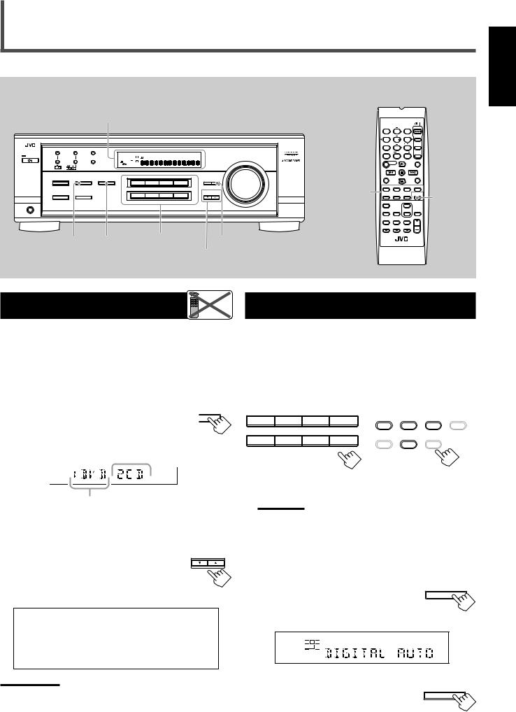
*“1DVD 2CD” is the initial setting. If you have already changed the setting, another combination will be shown.
2 Press CONTROL UP 5/DOWN ∞ to CONTROL
DOWN UP
select the appropriate digital terminal setting.
•Each time you press the button, the display changes as follows:
1 DVD 2 CD j 1 DVD 2 TV j 1 DVD 2 CDR j 1 CD 2 DVD j 1 CD 2 TV j 1 CD 2 CDR j 1 TV 2 DVD j 1 TV 2 CD j 1 TV 2 CDR j 1 CDR 2 DVD j 1 CDR 2 CD j 1 CDR 2 TV j (back to the beginning)
Note:
When shipped from the factory, the DIGITAL IN terminals can be used as the digital input for the following components:
–DIGITAL 1 (coaxial): For DVD player
–DIGITAL 2 (optical): For CD player
Selecting the Analog or Digital Input Mode
When you have connected digital source components using both the analog connections (see page 6) and the digital connections (see page 7) methods, you need to select the input mode correctly.
1Press one of the source selecting buttons—DVD, TV SOUND, CD, or TAPE/CDR*—for which you want to change the input mode.
DVD MULTI |
DVD |
VCR |
TAPE/CDR |
CD |
DVD DVD MULTI |
TV SOUND |
|
|
|||
CD |
TAPE/CDR |
FM |
FM/AM |
TV SOUND |
VCR |
AM |
|
|
SOURCE NAME
On the front panel From the remote control
Note:
*Among the sources listed above, you can select the digital input only for the sources which you have selected the digital input terminals for. (See “Setting the Digital Input (DIGITAL IN) Terminals” on the left column.)
2Select digital input mode.
On the front panel:
Press INPUT DIGITAL. |
INPUT DIGITAL |
|
|
“DIGITAL AUTO” appears on the display and |
|
the indicator for the detected signals also lights |
|
up. |
|
|
SPK |
|
DIGITAL AUTO |
L |
R |
LINEAR PCM |
S.WFR |
|
|
S |
|
|
|
CH- |
Ex: With the incoming signals of Linear PCM
To change the input mode back to analog |
INPUT ANALOG |
|
input, press INPUT ANALOG. |
INPUT ATT |
|
“ANALOG” appears on the display and the |
||
|
||
analog indicator also lights up. |
|
English
TO BE CONTINUED ON THE NEXT PAGE |
11 |
|
English
Basic Settings
From the remote control: |
/DIGITAL |
|
ANALOG |
Press ANALOG/DIGITAL.
The current setting indication appears on the display.
•Each time you press the button, the input mode alternates between the analog input (“ANALOG”) and the digital input (“DIGITAL AUTO”).
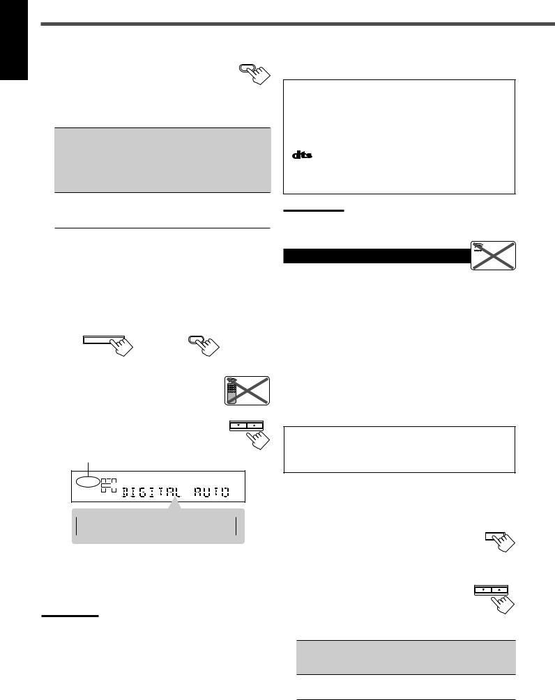
DIGITAL AUTO : Select this for the digital input mode. The receiver automatically detects the incoming signal format. (The DIGITAL AUTO indicator lights up on the display, then the digital signal indicator for the detected signals lights up.)
ANALOG : Select this for the analog input mode. (Initial setting when shipped from the factory.)
If the following symptoms occur while playing Dolby Digital or DTS Digital Surround software with “DIGITAL AUTO” selected, follow the procedure below:
–Sound does not come out at the beginning of playback.
–Noise comes out while searching or skipping chapters or tracks.
1Press INPUT DIGITAL (or ANALOG/DIGITAL on the remote control).
“DIGITAL AUTO” appears on the display.
INPUT DIGITAL |
ANALOG |
/DIGITAL |
On the front panel |
From the remote control |
||
2 Press CONTROL UP 5/DOWN ∞ to select |
Remote |
||
“DOLBY DIGITAL” or “DTS SURROUND” |
|||
NOT |
|||
while “DIGITAL AUTO” still remains on the |
|||
|
|||
display. |
|
DOWN UP |
|
|
|
CONTROL |
|
• Each time you press the button, the digital input mode changes as follows:
When “DOLBY DIGITAL” or “DTS
SURROUND” is selected, “DIGITAL AUTO” goes off.
SPK
DIGITAL AUTO L C R
S.WFR LFE
 DIGITAL LS S RS
 DIGITAL AUTO
 DTS SURROUND
 DOLBY DIGITAL
•To play back software encoded with Dolby Digital, select “DOLBY DIGITAL.”
•To play back software encoded with DTS Digital Surround, select “DTS SURROUND.”
Note:
When you turn off the power or select another source, “DOLBY
DIGITAL” and “DTS SURROUND” are canceled and the digital input mode is automatically reset to “DIGITAL AUTO.”
The following are the analog/digital signal indicators on the display to indicate what type of the signal comes into the receiver.
ANALOG : Lights when the analog input is selected. LINEAR PCM : Lights when Linear PCM signals come in.  DIGITAL : • Lights when Dolby Digital signals come in.
•Flashes when “DOLBY DIGITAL” is selected for software not encoded with Dolby
Digital signals.
: • Lights when DTS signals come in.
•Flashes when “DTS SURROUND” is selected for software not encoded with DTS signals.
Note:
When “DIGITAL AUTO” cannot recognize the incoming signals, no digital signal indicator lights up on the display.
Setting the Speaker Information  Remote
NOT
To obtain the best possible sound or effect from Surround modes (see pages 21–23), register the following speakers and subwoofer information after all connections are completed.
The following are items you can set:
•Subwoofer information—SUBWOOFER
•Speaker size—FRNT SP, CNTR SP, REAR SP
•Speaker distance—UNIT, FRNT DIS, CNTR DIS, REAR DIS
•Crossover frequency—CROSS
•Low frequency effect attenuator—LFE ATT
•Dynamic range compression—D. COMP
Before you start, remember...
There is a time limit in doing the following steps. If the setting is canceled before you finish, start from step 1 again.
“NO” for the subwoofer, “LARGE” for the front speakers, and “SMALL” for the center and rear speakers are initial settings. To get best possible sound, change the subwoofer and speaker settings to fit your listening conditions.
Subwoofer information
Register whether you have connected a subwoofer or not.
1 Press SETTING repeatedly until |
T SETTING |
“SUBWOOFER” (with the current |
|
setting) appears on the display. |
|
2 Press CONTROL UP 5/DOWN ∞ |
DOWN UP |
|
CONTROL |
to register whether you have |
|
connected a subwoofer or not. |
|
•Each time you press the button, the
subwoofer setting alternates between “YES” and “NO.”
YES : Select this when you have connected a subwoofer. You can adjust the subwoofer output level
(see page 15).
NO : Select this when you have not connected or have disconnected a subwoofer.
12
Speaker size
Register the sizes of all the connected speakers.
•When you change your speakers, register the information about the speakers again.
1 Press SETTING repeatedly until
“FRNT SP (Front speaker),” “CNTR SP (Center speaker),” or “REAR SP
(Rear speaker)” (with the current setting) appears on the display.
2 Press CONTROL UP 5/DOWN ∞ to CONTROL
DOWN UP
select the appropriate item about the speaker selected in the above step.
•Each time you press the button, the display changes as follows:
LARGE |
|
SMALL |
|
NONE
LARGE : Select this when the speaker size is relatively large. (See “Notes” below.)
SMALL : Select this when the speaker size is relatively small. (See “Notes” below.)
NONE : Select this when you have not connected a speaker. (Not selectable for the front speakers)
3Repeat steps 1 and 2 to select the appropriate items for other speakers.
Notes:
•Keep the following comment in mind as reference when adjusting.
–If the size of the cone speaker unit built in your speaker is greater than 12 cm (4 3/4 inches), select “LARGE,” and if it is smaller than
12 cm (4 3/4 inches), select “SMALL.”
•If you have selected “NO” for the subwoofer setting, you can only select “LARGE” for the front speaker setting.
•If you have selected “SMALL” for the front speaker setting, you cannot select “LARGE” for the center and rear speaker settings.
Speaker distance
Register the unit you use, then the speaker distance from your listening point.
•If you have set the unit before, start from step 3.
•Speaker distance is not valid for the DVD MULTI playback mode.
1 Press SETTING repeatedly until |
SETTING |
|
|
“UNIT” (with the current setting)* |
|
appears on the display. |
|
*“METER” is the initial setting. If you have already changed the setting, “FEET” will be shown.
2 Press CONTROL UP /DOWN |
|
to |
CONTROL |
5 |
∞ |
|
DOWN UP |
select the unit. |
|
|
|
• Each time you press the button, the setting alternates between “METER” and “FEET.”
METER : Speaker distance is shown in meter.
FEET : Speaker distance is shown in feet.
3 Press SETTING repeatedly until |
|
SETTING |
|
|
|
“FRNT DIS (Front distance),” “CNTR |
|
|
|
|
|
DIS (Center distance),” or “REAR DIS |
|
|
(Rear distance)” (with the current setting)* |
|
|
appears on the display. |
|
|
• The display shows the current setting in the unit selected in step 2.
*“3.0m” is the initial setting for meter and “10FT” is for feet. If you have already changed the setting, another value will be shown.
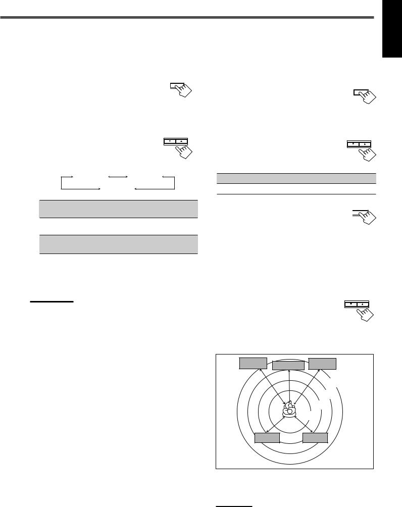
4 Press CONTROL UP 5/DOWN ∞ |
CONTROL |
|
DOWN UP |
to select the appropriate speaker |
|
distance. |
|
•If you have selected “METER” in step 2, the
value is changed from “0.3m” to “9.0m” by 0.3 m step.
•If you have selected “FEET” in step 2, the value is changed from “1FT” to “30FT” by 1 foot step.
Left front |
|
Right front |
speaker |
Center speaker |
speaker |
3.0 m
(10 feet)
2.7 m (9 feet)
2.4 m (8 feet)
2.1 m (7 feet)
Left rear |
Right rear |
speaker |
speaker |
English
Example: In this case,
set “FRNT DIS” to “3.0m” or “10FT,” set “CNTR DIS” to “2.7m” or “9FT” and, set “REAR DIS” to “2.4m” or “8FT.”
Note:
If you have selected “NONE” for the center and rear speakers setting, you cannot set the speaker distance for the center and rear speakers.
13
English
Basic Settings
Crossover frequency
Small speakers cannot reproduce the bass sounds efficiently. If you use a small speaker in any position, this receiver automatically reallocates the bass sound elements assigned from small speakers to large speakers.
To use this function properly, set this crossover frequency level according to the size of the small speaker connected.
•If you have selected “LARGE” for all speakers, this function will not take effect.
•Crossover frequency is not valid for DVD MULTI playback mode and HEADPHONE mode.
1Press SETTING repeatedly until “CROSS SETTING (Crossover)” (with the current setting)* appears on the display.
*“100HZ” is the initial setting. If you have already changed the setting, another frequency will be shown.
2Press CONTROL UP 5/DOWN ∞ to select the crossover frequency level you like to use.
•Each time you press the button, the crossover frequency level changes as follows:
80HZ 
 100HZ
100HZ 
 120HZ
120HZ
 200HZ
200HZ 
 150HZ
150HZ
CONTROL
DOWN UP
Low frequency effect attenuator
If the bass sound is distorted while playing back software using
Dolby Digital or DTS Digital Surround, follow the procedure below:
•Low frequency effect attenuator is not valid for the DVD MULTI playback mode.
•This function takes effect only when the subwoofer (LFE) signals come in, (with “SUBWOOFER” set to “YES”).
1 Press SETTING repeatedly until “LFE |
SETTING |
|
|
ATT (Low Frequency Effect Attenuator)” |
|
(with the current setting)* appears on the |
|
display. |
|
*“0dB” is the initial setting. If you have already changed the setting, “–10dB” will be shown.
2 Press CONTROL UP 5/DOWN ∞ to CONTROL
DOWN UP
select the low frequency effect attenuator level.
•Each time you press the button, the setting alternates between “0dB” and “–10dB.”
0dB : Normally select this.
–10dB : Select this when the bass sound is distorted.
Dynamic range compression
You can compress the dynamic range (difference between maximum sound and minimum sound) of the reproduced sound. This is useful when enjoying surround sound at night.
•This function takes effect only when playing back a source encoded with Dolby Digital.
1 Press SETTING repeatedly until |
SETTING |
“D. COMP (Dynamic range |
|
compression)” (with the current setting)* |
|
appears on the display. |
|
*“MID” is the initial setting. If you have already changed the setting, another setting will be shown.
2 Press CONTROL UP 5/DOWN ∞ |
CONTROL |
|
DOWN UP |
to select the appropriate compression |
|
level. |
|
•Each time you press the button, the display changes as follows:
OFF |
|
MID |
|
MAX
OFF : Select this when you want to enjoy surround with its full dynamic range. (No effect applied.)
MID : Select this when you want to reduce the dynamic range a little.
MAX : Select this when you want to apply the compression effect fully. (Useful at night.)
14
Sound Adjustments
English
Front Panel |
Remote Control |
Display
|
|
|
|
RX-6020V |
AUDIO/VIDEO CONTROL RECEIVER |
|
SUBWOOFER +/– |
|||
FM/AM TUNING |
FM/AM PRESET |
FM MODE |
|
|
|
|
|
|
|
SOUND |
|
|
|
|
LS |
S RS |
|
TUNED STEREO AUTOMUTING SLEEP |
|
||
STANDBY |
|
|
ANALOG |
SPK |
LOGIC ΙΙ DSP H.PHONE |
|
|
|||
|
|
MEMORY |
DIGITAL AUTO |
L |
C |
INPUT ATT |
VOLUME |
MASTER VOLUME |
|
|
|
|
LINEAR PCM |
S.WFR LFE |
|
|
|
|
|||
STANDBY/ON |
|
|
|
|
CH- |
|
|
|
|
|
SURROUND ON/OFF |
INPUT ANALOG |
INPUT DIGITAL |
|
|
|
|
ADJUST |
SETTING |
|
|
|
|
|
|
|
DVD MULTI |
DVD |
VCR |
TV SOUND |
|
|
|
INPUT ATT |
|
|
|
|
|
|
|
|
|
|
|
|
|
|
|
|
|
CONTROL |
|
|
SURROUND MODE |
SPEAKERS ON/OFF |
|
|
|
|
|
DOWN |
UP |
|
|
|
|
|
|
|
CD |
TAPE/CDR |
FM |
AM |
|
|
|
|
|
|
|
|
SOURCE NAME |
|
|
|
|
PHONES
INPUT ATT |
ADJUST CONTROL |
|
UP 5/DOWN ∞ |
|
|
A/V CONTROL |
STANDBY/ON |
|
|
|
RECEIVER |
|
|
TEST |
|
CENTER |
AUDIO |
|
1 |
|
2 |
3 |
|
EFFECT |
|
REAR L |
TV |
|
4 |
|
5 |
6 |
|
MENU |
|
REAR R |
VCR |
|
7/P |
|
8 |
9 |
|
ENTER |
|
SUBWOOFER |
DVD |
|
10 |
|
0 |
10 |
|
RETURN |
|
|
100 |
SLEEP |
SOUND |
|
|
||
REW |
|
|
FF |
|
REC PAUSE |
|
|
CD–DISC |
|
TAPE/CDR |
|
CD |
DVD |
DVD MULTI |
|
|
|
|
ANALOG |
FM/AM |
TV SOUND |
VCR |
/DIGITAL |
|
FM MODE |
|
|
|
|
|
|
|
ON/OFF |
|
DIMMER |
TV/VIDEO SURROUND |
MUTING |
||
|
|
|
MODE |
|
VCR CH |
|
TV CH |
TV VOLUME |
|
|
|
|
|
VOLUME |
REMOTE CONTROL RM -SRX6020J
Once each of following settings has been adjusted, this receiver memorizes the adjustments for each source.
Attenuating the Input Signal |
Remote |
|
NOT |
||
|
When the input level of the analog source is too high, sounds will be distorted. If this happens, you need to attenuate the input signal level to prevent the sound distortion.
INPUT ANALOG
1 Press and hold INPUT ATT (INPUT ANALOG) so that the INPUT ATT INPUT ATT indicator lights up on the display.
•Each time you press and hold the button, the Input Attenuator mode turns on (“INPUT ATT ON”) or off (“INPUT NORMAL”).
Note:
When selecting “DVD MULTI” as the source, this effect does not work.
Adjusting the Front Speakers |
Remote |
Output Balance |
NOT |
If the sounds you hear from the front right and left speakers are unequal, you can adjust the speaker output balance.
Before you start, remember...
There is a time limit in doing the following steps. If the setting is canceled before you finish, start from step 1 again.
1 Press ADJUST repeatedly until |
ADJUST |
“BALANCE” (with the current setting)* |
|
appears on the display. |
|
*“CNTR (Center)” is the initial setting. If you have already changed the setting, another setting will be shown.
2 Press CONTROL UP |
5/DOWN ∞ |
DOWN UP |
|
|
CONTROL |
to adjust the balance. |
|
|
•Pressing CONTROL UP 5 decreases the left channel output from “CNTR (Center)” to “L–21.”
•Pressing CONTROL DOWN ∞ decreases
the right channel output from “CNTR (Center)” to “R–21.”
Adjusting the Tone |
Remote |
|
NOT |
||
|
You can adjust the bass and treble sounds as you like.
Before you start , remember...
There is a time limit in doing the following steps. If the setting is canceled before you finish, start from step 1 again.
1 Press ADJUST repeatedly until “BASS” |
ADJUST |
or “TREBLE” (with the current setting)* |
|
appears on the display. |
|
*“0” is the initial setting. If you have already changed the setting, another number (level) will be shown.
BASS : To adjust the bass (–10 to +10).
TREBLE : To adjust the treble (–10 to +10).
2 Press CONTROL UP /DOWN |
|
to |
CONTROL |
5 |
∞ |
|
DOWN UP |
adjust the bass or treble sound level.
• Each time you press the button, the sound level changes by ±2 steps.
Adjusting the Subwoofer Output Level
You can adjust the subwoofer output level if you have connected a subwoofer and set the subwoofer information correctly—“YES.”
On the front panel:
Before you start, remember...
There is a time limit in doing the following steps. If the setting is canceled before you finish, start from step 1 again.
1 Press ADJUST repeatedly until |
ADJUST |
|
|
“SUBWFR (Subwoofer)” (with the |
|
current setting)* appears on the display. |
|
*“0” is the initial setting. If you have already changed the setting, another number (level) will be shown.
2Press CONTROL UP 5/DOWN ∞ to adjust the subwoofer output level (–10 to +10).
From the remote control:
1 Press SOUND.
10 keys are activated for sound adjustments.
CONTROL
DOWN UP
 SOUND
SOUND
2 Press SUBWOOFER +/– to adjust |
SUBWOOFER |
|
|
||
the subwoofer output level |
0 |
10 |
|
100 |
|
(–10 to +10). |
|
|
|
|
|
Note:
Subwoofer output level cannot be adjusted when using headphones.
15
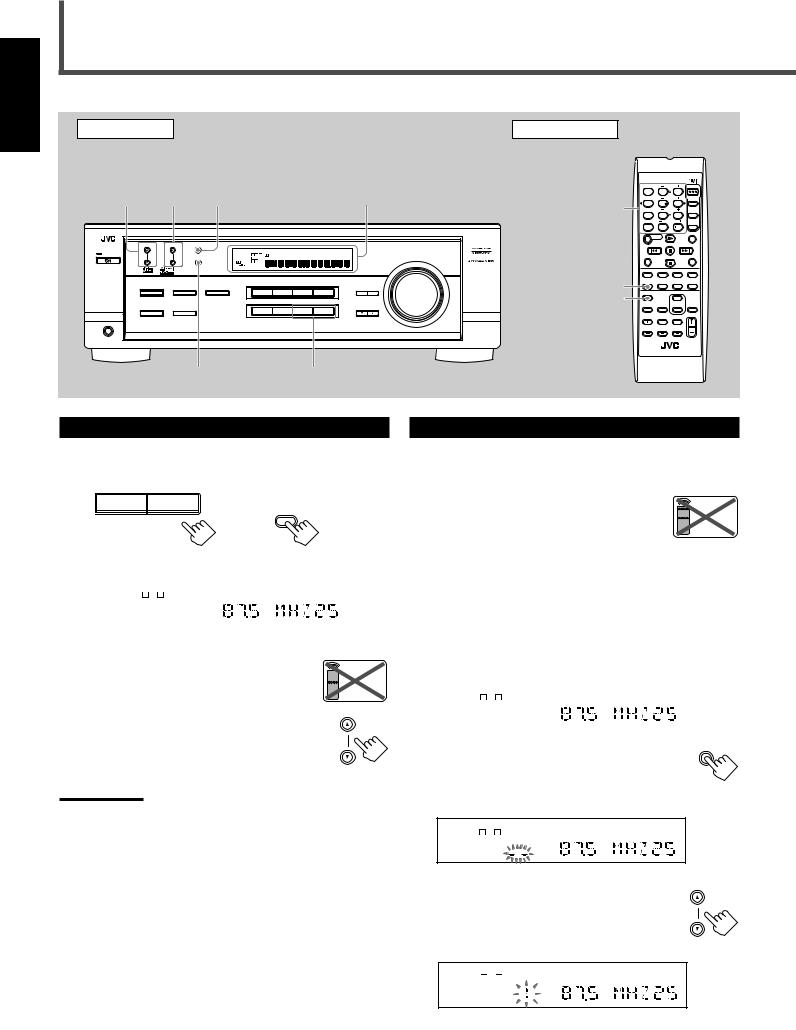
Tuner Operations
English
Front Panel |
|
|
|
|
|
|
Remote Control |
|
|
|
|
|
|
FM/AM |
FM/AM |
|
|
|
|
|
|
|
|
|
|
|
|
TUNING |
PRESET |
|
|
|
|
|
|
|
|
|
|
|
|
5 ∞ |
5/∞ |
|
|
|
|
|
|
|
|
RECEIVER |
|
||
/ |
|
|
|
|
|
|
|
|
|
|
A/V CONTROL |
STANDBY/ON |
|
(up/down) |
FM MODE |
|
|
Display |
|
TEST |
|
CENTER |
AUDIO |
||||
(up/down) |
|
|
|
EFFECT |
|
REAR L |
TV |
||||||
|
|
|
|
|
|
|
|
10 keys |
1 |
|
2 |
3 |
|
|
|
|
|
|
|
|
|
MENU |
|
REAR R |
VCR |
||
|
|
|
|
|
|
|
|
|
4 |
|
5 |
6 |
|
|
|
|
|
|
|
|
|
|
7/P |
|
8 |
9 |
|
|
|
|
|
|
|
|
|
|
ENTER |
|
SUBWOOFER |
DVD |
|
|
|
|
|
|
|
|
|
|
10 |
|
0 |
10 |
|
|
|
|
|
RX-6020V |
AUDIO/VIDEO CONTROL RECEIVER |
|
RETURN |
|
|
100 |
SLEEP |
||
|
|
|
|
|
|
|
|
|
SOUND |
|
|
||
FM/AM TUNING |
FM/AM PRESET FM MODE |
|
|
|
|
|
|
REW |
|
|
FF |
||
STANDBY |
|
|
ANALOG SPK |
|
TUNED STEREO AUTOMUTING SLEEP |
|
|
|
|
|
|
||
|
|
|
DIGITAL AUTO |
L C |
LOGIC ΙΙ DSP |
H.PHONE INPUT ATT |
VOLUME |
|
REC PAUSE |
|
|
CD–DISC |
|
|
|
MEMORY |
LINEAR PCM S.WFR LFE |
|
|
|
MASTER VOLUME |
|
|
|
|
|
|
|
|
|
|
LS S RS |
|
|
|
|
|
|
|
|
|
STANDBY/ON |
|
|
|
CH- |
|
|
|
|
|
|
|
|
|
|
|
|
|
|
|
|
|
|
TAPE/CDR |
|
CD |
DVD |
DVD MULTI |
|
|
|
|
|
|
|
|
FM/AM |
|
|
|
|
ANALOG |
|
|
|
|
|
|
|
|
FM/AM |
TV SOUND |
VCR |
/DIGITAL |
||
SURROUND ON/OFF |
INPUT ANALOG |
INPUT DIGITAL |
|
|
|
ADJUST SETTING |
|
|
|
|
|
||
|
|
|
|
DVD MULTI |
DVD |
VCR |
TV SOUND |
FM MODE |
FM MODE |
|
|
|
|
|
|
|
|
|
|
|
|
|
|
|
|
||
|
|
INPUT ATT |
|
|
|
|
|
|
|
|
ON/OFF |
|
|
|
|
|
|
|
|
|
CONTROL |
|
DIMMER |
TV/VIDEO SURROUND |
MUTING |
||
|
SURROUND MODE |
SPEAKERS ON/OFF |
|
|
|
|
DOWN UP |
|
|
|
|
MODE |
|
|
|
|
|
CD |
TAPE/CDR |
FM |
AM |
|
|
|
|
|
|
|
|
|
|
|
SOURCE NAME |
|
|
|
|
|
|
|
|
PHONES |
|
|
|
|
|
|
|
|
VCR CH |
|
TV CH |
TV VOLUME |
|
|
|
|
|
|
|
|
|
|
|
|
|
|
|
|
|
|
|
|
|
|
|
|
|
|
|
|
VOLUME |
|
|
|
|
|
|
|
|
|
REMOTE CONTROL RMSRX6020J |
||||
|
|
MEMORY |
|
|
FM, AM |
|
|
|
|
|
|
||
Tuning in Stations
1 Press FM or AM (FM/AM) to select the band.
The last received station of the selected band is tuned in.
FM |
AM |
FM/AM
On the front panel |
From the remote control |
||
|
|
|
|
|
ANALOG SPK |
TUNED STEREO AUTOMUTING |
|
|
L C R |
VOLUME |
|
|
S.WFR LFE |
|
|
|
LS S RS |
|
|
|
CH- |
|
|
|
|
|
|
Ex.: When the FM band is selected.
2Press FM/AM TUNING 5/∞
(up/down) repeatedly until you find the frequency you want.
•Pressing FM/AM TUNING 5 (up) increases the frequency.
•Pressing FM/AM TUNING ∞ (down) decreases the frequency.
Notes:

 Remote
NOT
FM/AM TUNING
•When you press and hold FM/AM TUNING 5/∞ (up/down) for few seconds in step 2, the frequency keeps changing until a station is tuned in.
•When a station of sufficient signal strength is tuned in, the TUNED indicator lights up on the display.
•When an FM stereo program is received, the STEREO indicator also lights up.
Using Preset Tuning
Once a station is assigned to a channel number, the station can be quickly tuned. You can preset up to 30 FM and 15 AM stations.
To store the preset stations

 Remote NOT
Before you start, remember...
There is a time limit in doing the following steps. If the setting is canceled before you finish, start from step 2 again.
1Tune in the station you want to preset (see “Tuning in Stations” on the left).
•If you want to store the FM reception mode for each preset station, select the FM reception mode. See “Selecting the FM
Mode” on page 17.
ANALOG |
SPK |
TUNED STEREO |
AUTOMUTING |
|
L C |
R |
VOLUME |
|
S.WFR LFE |
|
|
|
LS S |
RS |
|
|
|
CH- |
|
|
|
|
|
2 Press MEMORY. |
|
MEMORY |
|
|
|
||
The “CH-” indicator lights up and the channel |
|
||
number position starts flashing on the display for |
|
||
about 5 seconds. |
|
|
|
ANALOG SPK |
|
TUNED STEREO AUTOMUTING |
|
L C |
R |
VOLUME |
|
S.WFR LFE |
|
|
|
LS S |
RS |
|
|
CH- |
|
|
|
3 Press |
PRESET |
∞ (up/ |
FM/AM PRESET |
|
|
|
|
down) to select a channel number |
|
||
while the channel number position |
|
||
is flashing. |
|
|
|
ANALOG SPK |
|
TUNED STEREO AUTOMUTING |
|
L C |
R |
VOLUME |
|
S.WFR LFE |
|
|
|
LS S |
RS |
|
|
CH- |
|
|
|
16
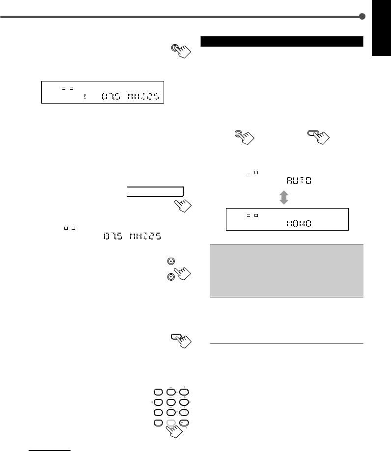
4 Press MEMORY again while the |
MEMORY |
selected channel number is flashing |
|
on the display. |
|
The selected channel number stops flashing.
The station is assigned to the selected channel number.
ANALOG |
SPK |
TUNED STEREO AUTOMUTING |
|
L C R |
VOLUME |
|
S.WFR LFE |
|
LS S RS
CH-
5 Repeat steps 1 to 4 for storing more stations.
To erase a stored preset station
Storing a new station on a used number erases the previously stored one.
To tune in a preset station
On the front panel:
1 Press FM or AM to select the |
|
|
|
FM |
|
|
AM |
|||
|
|
|
|
|
||||||
|
|
|
|
|||||||
band. |
|
|
|
|
|
|
|
|
|
|
|
|
|
|
|
|
|
|
|
||
|
|
|
|
|
|
|
|
|
||
The last received station of the |
|
|
|
|
|
|
|
|
|
|
selected band is tuned in. |
|
|
|
|
|
|
|
|
|
|
|
|
|
|
|
|
|
|
|
|
|
|
ANALOG SPK |
TUNED |
STEREO AUTOMUTING |
|
|
|
||||
|
L C R |
|
|
|
|
VOLUME |
|
|
|
|
|
S.WFR LFE |
|
|
|
|
|
|
|
|
|
|
LS S RS |
|
|
|
|
|
|
|
|
|
|
CH- |
|
|
|
|
|
|
|
|
|
|
|
|
|
|
|
|
|
|
|
|
2 Press FM/AM PRESET 5/∞ |
|
|
|
|
FM/AM PRESET |
|||||
|
|
|
|
|
|
|
|
|||
(up/down) repeatedly until you find |
|
|
|
|||||||
the channel you want. |
|
|
|
|
|
|
|
|
|
|
|
|
|
|
|
|
|
|
|
||
•Pressing FM/AM PRESET 5 (up) increases the channel numbers.
•Pressing FM/AM PRESET ∞ (down) decreases the channel numbers.
From the remote control:
1 Press FM/AM to select the band (FM or |
FM/AM |
|
|
AM). |
|
The last received station of the selected band is tuned in and 10 keys now work for tuner operation.
•Each time you press the button, the band alternates between FM and AM.
2Press 10 keys to select a preset channel number.
•For channel number 5, press 5.
•For channel number 15, press +10 then 5.
•For channel number 20, press +10 then 10.
•For channel number 30, press +10, +10, then 10.
Note:
TEST |
|
CENTER |
1 |
2 |
3 |
EFFECT |
|
REAR |
4 |
5 |
6 |
MENU |
|
REAR |
7/P |
8 |
9 |
ENTER |
SUBWOOFER |
|
10 |
0 |
10 |
RETURN |
|
100 |
When you use 10 keys on the remote control, be sure that they are activated for the tuner, not for the CD player and others. (See page 28.)
Selecting the FM Reception Mode
When an FM stereo broadcast is hard to receive or noisy, you can change the FM reception mode while receiving an FM broadcast.
•You can store the FM reception mode for each preset station (see page 16).
1While listening to an FM station, press FM MODE.
•Each time you press the button, the FM reception mode alternates between “AUTO” and “MONO.”
FM MODE FM MODE
On the front panel |
From the remote control |
||
|
|
|
|
|
ANALOG SPK |
TUNED STEREO AUTOMUTING |
|
|
L C R |
|
|
|
S.WFR LFE |
|
|
|
LS S RS |
|
|
|
CH- |
|
|
|
|
|
|
ANALOG |
SPK |
TUNED |
|
L C |
R |
S.WFR LFE
LS S RS
CH-
AUTO : Normally select this.
When a program is broadcasted in stereo, you will hear stereo sound; when in monaural, you will hear monaural sounds. This mode is also useful to suppress static noise between stations. The AUTO MUTING indicator lights up on the display. (Initial Setting)
MONO : Select this to improve the reception (but stereo effect will be lost).
In this mode, you will hear noise while tuning into the stations. The AUTO MUTING indicator goes off from the display. (The STEREO indicator also goes off.)
English
17
English
Creating Realistic Sound Fields
You can use the following Surround modes to reproduce a realistic sound field:
■Dolby Surround
•Dolby Pro Logic II
•Dolby Digital
■DTS Digital Surround
■DAP modes
■All Channel Stereo
■Dolby Surround
Dolby Pro Logic II*
Dolby Pro Logic II has a newly developed multichannel playback format to decode all 2 channel sources—regular stereo source and Dolby Surround encoded source—into 5.1 channel.
Matrix-based encoding/decoding method for Dolby Pro Logic II makes no limitation for the cutoff frequency of the rear treble and enables stereo rear sound compared to conventional Dolby Pro Logic.
Dolby Pro Logic II enables to reproduce spacious sound from original sound without adding any new sounds and tonal colorations. Dolby Pro Logic II has two modes—Movie mode and Music mode:
Pro Logic II Movie (PL II MOVIE)—suitable for reproduction of Dolby Surround encoded sources bearing the mark 


 . You can enjoy soundfield very close to the one created with discrete 5.1 channel sounds.
Pro Logic II Music (PL II MUSIC)—suitable for reproduction of any 2 channel stereo music sources. You can enjoy wide and deep sound by using this mode. For this mode, Panorama control can be selected, which gives “wraparound” sound effect with side-wall image.
•When Dolby Pro Logic II is activated,  PRO LOGIC II indicator lights up on the display.
Dolby Digital*
Used to reproduce multichannel sound tracks of the software encoded with Dolby Digital ( D I G I T A L ).
•To enjoy the software encoded with Dolby Digital, connect the source component using the digital terminal on the rear of this receiver. (See page 7.)
Dolby Digital 5.1 ch encoding method (so-called discrete multichannel digital audio format) records and digitally compresses the left front channel, right front channel, center channel, left rear channel, right rear channel, and LFE channel signals.
Since each channel is completely independent from the other channel signals to avoid interference, you can obtain much better sound quality with much stereo and surround effects.
Note:
Dolby Digital software can be roughly grouped into two categories
—multichannel (up to “5.1” ch) and 2 channel software. To enjoy surround sounds while playing Dolby Digital 2 ch software, you can use Dolby Pro Logic II.
■ DTS Digital Surround**
Used to reproduce multichannel sound tracks of the software encoded with DTS Digital Surround  ).
).
•To enjoy the software encoded with DTS Digital Surround, connect the source component using the digital terminal on the rear of this receiver. (See page 7.)
DTS Digital Surround is another discrete multichannel digital audio format available on CD, LD, and DVD software. Compared to Dolby Digital, audio compression ratio is relatively low. This fact allows DTS Digital Surround format to add breadth and depth to the reproduced sounds. As a result, DTS Digital Surround features natural, solid and clear sound.
Typical Multichannel (5.1 ch) reproduction
|
Center |
|
speaker |
Left front |
Right front |
speaker |
Subwoofer speaker |
Left rear |
Right rear |
speaker |
speaker |
*Manufactured under license from Dolby Laboratories. “Dolby,” “Pro Logic,” and the double-D symbol are trademarks of Dolby Laboratories. Confidential Unpublished Works. ©1992–1997 Dolby Laboratories, Inc. All rights reserved.
**Manufactured underlicense from Digital Theater Systems, Inc. US
PAT. No. 5,451,942 and other world-wide patents issued and pending. “DTS” and “DTS Digital Surround” are trademarks of
Digital Theater Systems, Inc. Copyright 1996 Digital Theater
Systems, Inc. All rights reserved.
18
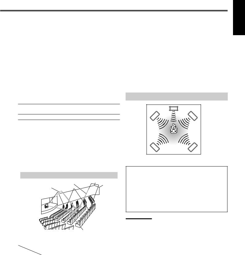
■ DAP (Digital Acoustic Processor) modes
DAP modes have been designed to create important acoustic surround elements.
The sound heard in a live club, dance club, hall or pavilion consists of direct sound and indirect sound—early reflections and reflections from behind. Direct sounds reach the listener directly without any reflection. On the other hand, indirect sounds are delayed by the distances of the ceiling and walls (see the diagram below).
These indirect sounds are important elements of the acoustic surround effects. The DAP mode can reproduce a realistic sound field by adding these indirect sounds.
DAP modes can be used when the front and rear speakers are connected to this receiver (without respect to the center speaker connection: no sound comes out of the center speaker even if it is connected).
The following DAP modes are provided with this receiver:
LIVE CLUB : Gives the feeling of a live music club with a low ceiling.
DANCE CLUB : Gives a throbbing bass beat.
HALL |
: Gives clear vocal and the feeling of a concert |
|
hall. |
|
|
PAVILION |
: Gives the spacious feeling of a pavilion with a |
|
high ceiling. |
|
|
These DAP modes can be used to add the acoustic surround effects while reproducing 2 channel stereo software—either analog or digital except Dolby Digital and DTS Digital Surround—and can give you a real “being there” feeling.
•When one of the DAP modes is selected, the DSP indicator lights up on the display.
Creating sound field
Reflections from behind
Early reflections
Direct sounds
■ All Channel Stereo
This mode can reproduce a larger stereo sound field using all the connected (and activated) speakers.
All Channel Stereo can be used when the front and rear speakers are connected to this receiver without respect to the center speaker connection.
If the center speaker is connected and activated, the same phase of the front left and right signals are output through the center speaker.
All Channel Stereo can be used while reproducing 2 channel stereo software, either analog or digital except Dolby Digital and DTS Digital Surround.
•When All Channel Stereo is selected, the DSP indicator lights up on the display.
All Channel Stereo reproduction
Sound reproduced from All Channel Stereo
DVD MULTI Playback Mode
This receiver provides the DVD MULTI Playback Mode for reproducing the analog discrete 5.1 channel output mode of the DVD player or other equipment.
You can adjust speaker output levels while playing back a video software such as a DVD using the analog discrete 5.1 channel output mode.
•For connecting analog discrete output jacks, see page 7.
•For details on the DVD MULTI Playback Mode, see page 24.
Note:
When you select “DVD MULTI” as the source to play, Surround mode is canceled, and the SURROUND ON/OFF and SURROUND MODE buttons do not work.
Available Surround modes for each input signal |
|
|
|
: Possible / : Impossible |
|||||||
Mode |
SURROUND |
DOLBY |
DTS |
PLII |
PLII |
LIVE |
DANCE |
HALL |
PAVILION |
ALL CH |
|
Signals |
OFF (stereo) |
DIGITAL |
SURROUND |
MOVIE |
MUSIC |
CLUB |
CLUB |
STEREO |
|||
|
|
||||||||||
|
|
|
|
|
|
|
|
|
|
|
|
Dolby Digital |
|
|
|
|
|
|
|
|
|
|
|
(Multichannel) |
|||||||||||
|
|
|
|
|
|
|
|
|
|
||
|
|
|
|
|
|
|
|
|
|
|
|
Dolby Digital |
|
|
|
|
|
|
|
|
|
|
|
(2 channel) |
|||||||||||
|
|
|
|
|
|
|
|
|
|
||
|
|
|
|
|
|
|
|
|
|
|
|
DTS Digital |
|
|
|
|
|
|
|
|
|
|
|
Surround |
|
|
|
|
|
|
|
|
|
|
|
(Multichannel) |
|
|
|
|
|
|
|
|
|
|
|
|
|
|
|
|
|
|
|
|
|
|
|
DTS Digital |
|
|
|
|
|
|
|
|
|
|
|
Surround |
|
|
|
|
|
|
|
|
|
|
|
(2 channel) |
|
|
|
|
|
|
|
|
|
|
|
|
|
|
|
|
|
|
|
|
|
|
|
Linear PCM |
|
|
|
|
|
|
|
|
|
|
|
|
|
|
|
|
|
|
|
|
|
|
|
Analog |
|
|
|
|
|
|
|
|
|
|
|
|
|
|
|
|
|
|
|
|
|
|
|
English
19
Loading...