


 Loading...
SERVICE MANUAL
Mobile mini note PC
MP-XV941DE, MP-XV841DE, MP-XV841GB,MP-XV841GBEX, MP-XV841US
|
Area Suffix |
DE |
---------- Germany |
GB |
--------------- U.K. |
US |
------------- U.S.A. |
|
|
TABLE OF CONTENTS
1 PRECAUTION. . . . . . . . . . . . . . . . . . . . . . . . . . . . . . . . . . . . . . . . . . . . . . . . . . . . . . . . . . . . . . . . . . . . . . . . . 1-2 2 SPECIFIC SERVICE INSTRUCTIONS . . . . . . . . . . . . . . . . . . . . . . . . . . . . . . . . . . . . . . . . . . . . . . . . . . . . . . 1-2 3 DISASSEMBLY . . . . . . . . . . . . . . . . . . . . . . . . . . . . . . . . . . . . . . . . . . . . . . . . . . . . . . . . . . . . . . . . . . . . . . . 1-3 4 ADJUSTMENT . . . . . . . . . . . . . . . . . . . . . . . . . . . . . . . . . . . . . . . . . . . . . . . . . . . . . . . . . . . . . . . . . . . . . . . 1-10 5 TROUBLESHOOTING . . . . . . . . . . . . . . . . . . . . . . . . . . . . . . . . . . . . . . . . . . . . . . . . . . . . . . . . . . . . . . . . . 1-11
COPYRIGHT © 2004 Victor Company of Japan, Limited
No.XE003
2004/7
SECTION 1
PRECAUTION
This service manual does not describe PRECAUTION.
SECTION 2
SPECIFIC SERVICE INSTRUCTIONS
This service manual does not describe SPECIFIC SERVICE INSTRUCTIONS.
1-2 (No.XE003)
SECTION 3
DISASSEMBLY
3.1Disassembly procedure
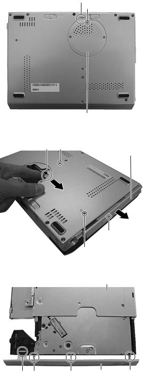
3.1.1 Removing the DIMM cover(See Figure 1)
(1)Remove three screws A from the DIMM cover on the bottom of the main unit.
(2)Remove the DIMM cover by lifting it up from the gap a.
Gap a
A
A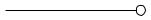
 A
A
3.1.2 Removing the DVD drive unit(See Figure 2)
•Prior to the following procedure, DIMM cover should be removed.
(1)Remove two screws B, which are attached to the DVD drive unit, from the bottom of the main unit.
(2)Push part b in the direction indicated by the arrow, then pull out the DVD drive unit by sliding outward.
3.1.3 Removing the fitting(See Figure 2, Figure 3)
•Prior to the following procedure, DVD drive unit should be removed.
(1)Eject the tray by inserting a piece of fine wire into the small hole c.
(2)Disengage three tabs d, and then disengage one hook e.
*Pay special attention not to damage either the tabs or the hooks.
DIMM Cover
Fig.1
Part b B
DVD Drive unit
Hole c
B
Fig.2
DVD Drive unit
Hook e Tab d |
Tab d |
Fitting |
Tab d |
Fig.3
(No.XE003)1-3

3.1.4 Removing the keyboard assembly(See Figure 4 , Figure 5,Figure 6)
(1)Individually push three latches f in the upper part of the keyboard with a single-slotted or flat screwdriver, and then lift the keyboard assembly upward.
Latch f
(2)Pull out the card wires from the connectors CON6 and CON8 on the main board respectively.
Latch f
 Latch f
Keyboard
Fig.4
 2
2
Removes
1  1
1
2
Attach
Fig.5
Main board
Keyboard CON6 |
CON8 |
Fig.6
1-4 (No.XE003)
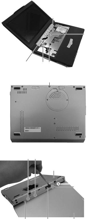
3.1.5 Removing the hinge cover(See Figure 7 ,Figure 8, Figure 9)
(1)Remove one screw C and two screws B from the hinge cover.
C :short D :long
(2)Disconnect one card wire from the connector CON5 on the main board.
(3) Remove one screw E from the bottom of the main unit.
(4)Leave the LCD panel open. Release four tabs g on the hinge cover by slowly inserting a single-slotted or flat screwdriver into the slot of the battery terminal.
*Please make sure not to damage either the hinge cover or the bottom case when releasing the tabs.
(5)Slowly remove the hinge cover in the direction indicted by the arrow.
D
CON5
Hinge cover |
C D |
|
|
|
Fig.7 |
|
E |
Fig.8
Tab g Tab g
Bottom case
 Tab g
Tab g
Tab g
Hinge cover Battery terminal LCD Panel assembly
Fig.9
(No.XE003)1-5
Loading...