


 Loading...
IP CAMERA
VN-V25U |
INSTRUCTIONS |
VN-V26U |
(Setting) |
|
|
VN-X35U |
|
VN-V225U series |
|
VN-X235U series |
|
Thank you for purchasing this JVC product. Before operating this unit, please read the instructions carefully to ensure the best possible performance.
LST0886-001A

Getting Started
Contents |
|
Getting Started |
|
Contents ................................................... |
2 |
Network Settings |
|
Network Requirements ............................. |
3 |
IP Address Settings .................................. |
6 |
IP address setting procedure............... |
6 |
IP address setting at the computer...... |
7 |
Internet Explorer Setting..................... |
8 |
Connecting the camera to the computer.... |
10 |
IP address setting for the camera........ |
12 |
Enter user name and password........... |
14 |
Setting Using Internet Explorer |
|
Setting ...................................................... |
16 |
How to open the setting page.............. |
16 |
Basic Settings1.................................... |
17 |
Basic Settings2.................................... |
18 |
Camera Page ...................................... |
21 |
Encoding Page .................................... |
26 |
Audio Page .......................................... |
28 |
Alarm Page.......................................... |
30 |
Alarm Environment Page..................... |
34 |
PTZ Page ............................................ |
38 |
Auto Patrol Page ................................. |
39 |
Privacy Mask Page.............................. |
41 |
Motion Detection Page ........................ |
43 |
Network Basic Page ........................... |
45 |
Network Details Page .......................... |
46 |
Protocol Page ...................................... |
47 |
Streaming Page................................... |
48 |
Access Restrictions Page.................... |
50 |
Time Page ........................................... |
52 |
Password Page ................................... |
53 |
Maintenance Page............................... |
54 |
LED State Page................................... |
55 |
List of Factory Settings of Each Page ... |
56 |
Miscellaneous Page ............................ |
59 |
Operation Page ................................... |
60 |
Settings Page ...................................... |
61 |
Position List ......................................... |
64 |
Patrol Settings ..................................... |
65 |
Operation |
|
Operation of Built-in Viewer...................... |
66 |
Screen Configuration........................... |
66 |
lmage Settings..................................... |
68 |
PTZ Settings........................................ |
70 |
PTZ Control ......................................... |
72 |
JPEG Viewer Settings ......................... |
74 |
MPEG4 Viewer Settings...................... |
76 |
Audio Monitor Settings ........................ |
78 |
Operator Password ............................. |
80 |
Exiting the Viewer................................ |
81 |
Others |
|
Troubleshooting........................................ |
82 |
How to Read this Manual
Symbols used in this manual
Note :States precautions to be taken during operation.
Memo :States restrictions on the functions or use of this equipment. For reference purposes.
A:Indicates the page numbers or items to refer to.
Contents of this manual
●This manual contains instructions for setting the network and Internet Explorer, and operating the Built-in Viewer.
●JVC holds the copyright to this manual. Any part or all of this manual may not be reproduced without prior consent from the company.
●Windows is a registered trademark of Microsoft Corporation in the U.S.
●Product names of other companies described in this manual are trademarks or registered trademarks of the respective companies. Symbols such as , and are omitted in this manual.
●Design, specifications and other contents described in this manual are subject to change for improvements without prior notice.
●Screen displays in this manual may differ from the actual ones.
●For details on mounting the camera, please refer to the attached [READ ME FIRST] and the [INSTRUCTIONS (Installation)] (pdf) in the bundled CD-ROM.
●The model name and series name are stated for functions or setting values that are unique to the model.
●This manual corresponds to firmware V2.00 or later. (VN-V25U, VN-V26U and VN-X35U only)
2

Network Settings
Network Requirements
●Ensure that there is sufficient network bandwidth for the data volume to be sent out by camera. Do not send multicast stream that exceeds the bandwidth. If the entire bandwidth is used by the multicast stream, control of this camera via the network may fail.
●Data volume to be sent by camera varies with the settings and number of distributions.
●The maximum bit rate for transmission is about 20 Mbps.
Estimation of Total Bit Rate
The total JPEG bit rate from camera is determined by the camera settings, number of clients, and the client’s requested number of frames. The total MPEG4 bit rate from camera is determined by the number of distributions. Develop a design upon taking the above into consideration.
Bit Rate of JPEG Stream
The JPEG file size per frame varies with the encoding settings as well as input video signals. The following table shows typical sizes. When VFS is selected, the quantization table during JPEG encoding will be maintained, and the file size will increase/decrease according to the input signals. When AFS is selected, encoding will be performed such that the target file size is the average size of multiple JPEG images.
AFS (Average File Size)
(TX) is applicable to VN-X series only.
Selectable Range for Distribution File Size
Quad |
VGA |
QVGA |
|
VGA(TX) |
|||
|
|
||
|
|
|
|
40 KB to |
10 KB to |
3 KB to 33 KB |
|
200 KB |
100 KB |
|
|
|
|
|
VFS(Variable File Size)
(TX) is applicable to VN-X series only.
|
|
|
Distribution File Size |
||
|
|
|
(typical sizes) |
||
|
|
|
|
|
|
|
|
|
Quad |
VGA |
QVGA |
|
|
|
(TX) |
|
|
|
|
|
|
|
|
Setting |
1 |
(High) |
180 KB |
80 KB |
27 KB |
Values |
|
|
|
|
|
2 |
|
160 KB |
60 KB |
20 KB |
|
for |
|
|
|
|
|
Picture |
3 |
|
140 KB |
40 KB |
13 KB |
Quality |
|
|
|
|
|
4 |
|
120 KB |
30 KB |
10 KB |
|
|
|
||||
|
(Medium) |
|
|
|
|
|
|
|
|
|
|
|
5 |
|
100 KB |
25 KB |
8 KB |
|
|
|
|
|
|
|
6 |
|
80 KB |
20 KB |
7 KB |
|
|
|
|
|
|
|
7 |
(Low) |
60 KB |
15 KB |
5 KB |
|
|
|
|
|
|
The maximum number of distributions varies with the bit rate settings as well as the client’s requested frame rate. Up to 20 streams can be distributed (including multicast). The total frame rate refers to the sum of these frame rates.
For example, when 10 fps is requested by two clients, and in addition, multicast is transmitted at a rate of 10 fps, the total frame rate will be:
10 + 10 + 10 = 30 fps
For example, when 5 fps is requested by two clients, and in addition, multicast is transmitted at a rate of 5 fps, the total frame rate will be:
5 + 5 + 5 = 15fps
If JPEG file size per piece is 120KB, total bit rate will be:
120KB 15fps = 1800KB/s = 14.4Mbps
Bit Rate of MPEG4 Stream
You can select either the Variable Bit Rate (VBR) or Constant Bit Rate (CBR) system for MPEG4 stream.
When the VBR system is selected, the bit rate varies according to the condition of the input video signals. The VBR system delivers a stable picture quality, but forecast of the bit rate is difficult. When the CBR system is selected, encoding is performed at a fixed bit rate regardless of the condition of the input video signals. The picture quality varies under the CBR system, but the bit rate can be easily forecasted.
You can specify an estimated bit rate for both VBR and CBR. (64 kbps to 8000 kbps)
3

Network Settings
Network Requirements (continued)
Bit Rate of Audio
Only 1 audio data stream can be received. Data volume for 1 audio stream is 64 kbps. Audio data volume may be calculated using the following formula.
64 kbps x no. of streams
The number of streams is the total number of streams sent via TCP (number of clients), streams sent via multicast, and stream received by camera
(Example) When camera sends out 2 audio streams and receives 1 audio stream, data volume will be as follows. 64 kbps x 3 = 192 kbps
Restrictions on the Number of Distributions for camera
The maximum number of distributions for camera is determined by the settings as well as requirements from the client.
For JPEG distribution, you can select either “Frame Rate Priority” mode or “Client number Priority” mode. “Frame Rate Priority” mode distributes JPEG images according to the frame rate requested by the client. The maximum number of distributions is determined based on the highest bit rate within the distribution streams. For “Client number Priority” mode, if there are requests from multiple clients, JPEG images are distributed in a lower frame rate than that requested to cater to multiple clients. It can accept 20 distribution requests as the maximum number of clients.
When Frame Rate Priority Mode is Selected
JPEG images are distributed at the frame rate requested by the client.
When a distribution request that exceeds the maximum number of distributions is received, this request is denied. ● When only JPEG images are distributed
For example, if Client A requests for JPEG at 1 Mbps, while Client B requests for JPEG at 5 Mbps, additional 2 streams (total 4 streams) of distribution are possible for request below 5 Mbps.
Maximum number of distributions when only JPEG data is distributed
Distribution |
Maximum |
Total |
at maximum |
number of |
maximum bit |
bit rate |
distributions |
rate |
|
|
|
1 Mbps and |
20 |
20 Mbps |
below |
|
|
|
|
|
5 Mbps and |
4 |
20 Mbps |
below |
|
|
|
|
|
10 Mbps and |
2 |
20 Mbps |
below |
|
|
|
|
|
Larger than |
1 |
Maximum |
10 Mbps |
|
configurable |
|
|
value |
|
|
(24 Mbps) |
|
|
|
● When both JPEG and MPEG4 images are distributed
When both JPEG and MPEG4 images are distributed simultaneously, distribution up to two clients for JPEG and three clients for MPEG4 respectively is possible.
However, distribution requests that exceed a total bit rate of 20 Mbps will be denied.
Maximum number of distributions when JPEG and MPEG4 data is distributed
Maximum number |
Maximum number |
|
of distributions |
of distributions for |
Total bit rate |
for JPEG |
MPEG4 |
|
|
|
|
2 |
3 |
20 Mbps and |
|
|
below |
|
|
|
● When only MPEG4 images are distributed
The maximum number of distributions is determined by the preset bit rate. When a distribution request that exceeds the maximum number of distributions is received, this request is denied.
When distributing only MPEG4 data
Preset bit |
Maximum |
Total maximum |
|
number of |
|||
rate |
bit rate |
||
distributions |
|||
|
|
||
|
|
|
|
0.6 Mbps and |
20 |
12 Mbps |
|
below |
|
|
|
|
|
|
|
3 Mbps and |
4 |
12 Mbps |
|
below |
|
|
|
|
|
|
|
4 Mbps and |
3 |
12 Mbps |
|
below |
|
|
|
|
|
|
|
6 Mbps and |
2 |
12 Mbps |
|
below |
|
|
|
|
|
|
|
Larger than |
1 |
Maximum |
|
6 Mbps |
|
configurable value |
|
|
|
(8 Mbps) |
|
|
|
|
When Client number Priority Mode is Selected
●When only JPEG images are distributed
If the distribution request would be accepted in the frame rate priority mode, distribution works in the same way as frame rate priority mode, where JPEG images are distributed at the frame rate requested by the client. If the distribution request would be denied in the frame rate priority mode, the frame rate is controlled such that the maximum bit rate is as shown in the following table, to accept distribution requests from up to 20 clients. For example, if Client A and B request for JPEG at 10 Mbps, and Client C requests for JPEG at 5 Mbps, the frame rate will be reduced such that the distribution bit rate to each client is less than 5 Mbps.
Maximum bit rate when only JPEG data is distributed
Current number of |
Maximum bit rate |
Total maximum bit |
distributions |
|
rate |
|
|
|
2 and below |
10 Mbps |
20 Mbps |
|
|
|
3 to 4 |
5 Mbps |
20 Mbps |
|
|
|
5 to 20 |
1 Mbps |
20 Mbps |
|
|
|
4

● When both JPEG and MPEG4 images are distributed When both JPEG and MPEG4 images are distributed, distribution works in the same way as frame rate priority mode if the distribution request would be accepted in the frame rate priority mode. If the distribution request would be denied in the frame rate priority mode, the frame rate is controlled such that the maximum bit rate is as shown in the following table, to accept distribution requests for up to a total number of 20 JPEG and MPEG distributions. However, distribution requests for which the total bit rate of the MPEG4 distribution stream exceeds 10 Mbps will be denied.
Maximum JPEG bit rate when only JPEG and MPEG4 data is distributed
Current number |
Maximum bit rate |
Total maximum |
of distributions |
|
bit rate |
|
|
|
2 and below |
5 Mbps |
10 Mbps |
|
|
|
3 to 4 |
2.5 Mbps |
10 Mbps |
|
|
|
5 to 20 |
0.5 Mbps |
10 Mbps |
|
|
|
When only MPEG4 images are distributed, the maximum number of distributions is determined by the preset bit rate. When a distribution request that exceeds the maximum number of distributions is received, this request is denied.
When distributing only MPEG4 data (A Page 4)
Memo:
●If the bit rate is changed when image distribution is in progress, the restriction on distribution may not work correctly.
Insufficient network bandwidth
When there is insufficient bandwidth, the number of JPEG frames (frame rate) that the client can acquire will decrease. Delay will also occur in the distribution of images. In the case of MPEG4, noise interference may occur and playback may fail. There may be a longer delay or interruption in the audio.
Network Delay
When the client acquires JPEG via TCP, camera will send out data while checking the ACK from the client at the same time. For networks with considerable delay, data cannot be sent out until ACK is received, and therefore the frame rate will drop. In the case of MPEG4, noise interference may occur and playback may fail. Audio may be interrupted.
Decrease in the frame rate due to network delays can be eliminated by receiving data via multicast.
Network Jitter
When there is considerable network jitter, delay time may be prolonged and the image frame rate may drop. In the case of MPEG4, noise interference may occur and playback may fail. Audio may be interrupted.
Packet Loss
When acquiring images from camera via TCP, packet loss may be recovered by TCP transmission. When there is considerable delay in the network, however, missing data may occur and the image frame rate may drop. In the case of MPEG4, noise interference may occur and playback may fail.
Audio may be interrupted.
When packet loss occurs during multicast sending from camera, the image frame rate may drop. In the case of MPEG4, noise interference may occur and playback may fail.
Audio may be interrupted.
List of Protocols and Port Numbers Used by camera
camera uses the protocols and port numbers listed below. Ensure that these ports are allowed through the firewall when a firewall is to be installed.
Protocol/Port No. |
Purpose of Use |
|
|
Source |
|
|
|
TCP/80 |
JPEG/MPEG4 |
|
acquisition, Web |
|
Settings page, API, |
|
Sending/Acquisition |
|
of sound |
|
|
TCP/5510 |
VSIP |
|
|
UDP/5510 |
VSIP |
|
|
UDP/9541 |
VSIP discovery |
|
protocol |
|
|
TCP/10020 |
(Reserved for |
TCP/10021 |
adjustment) |
TCP/10023 |
|
|
|
TCP/32040 |
Alarm server |
|
|
TCP/49298 |
Sound data reception |
|
|
Destination |
|
|
|
TCP/20, 21 |
FTP |
|
|
TCP/25 |
Mail delivery |
|
|
TCP/110 |
POP (Mail Delivery) |
|
|
TCP/User Setting No. |
Sending alarm |
|
|
UDP/123 |
SNTP |
|
|
UDP/User Setting No. |
Sending alarm |
|
|
5

Network Settings
IP Address Settings
IP address setting procedure
Follow the procedure below to configure the IP address of the camera.
Step1 IP address setting at the computer
(APage 7)
Set the IP address of the computer for configuring the camera settings.
G
Step2 Internet Explorer Setting (APage 8)
Configure the Internet Explorer settings in order to establish connection between the computer and the camera.
G
Step3 Connecting the camera to the computer
(APage 10)
Connect the computer and the camera.
G
Step4 IP address setting for the camera (APage 12)
Set the [IP Setting] item on the [Basic Settings1] screen to ADHCP DisableB or ADHCP EnableB.
Set up the computer for setting the IP address.
●Minimum computer specifications for
setting |
|
|
OS |
: Windows XP (Professional or |
|
|
Home Edition) (SP2) |
|
Web browser |
|
|
|
: Internet Explorer Version 6.0 |
|
|
XP |
: Version 6.0 |
|
Vista |
: Version 7.0 |
Note:
●When setting the IP address of the camera, do so by using a network that is made up of only the camera, the computer for setting and the switching hub.
●Using a hub connected to other network devices or networks via a LAN cable for setting can cause problems.
System configuration required for setting IP address
Camera at factory default is set to ADHCP DisableB (DHCP client function is Off), it will activate under the following IP address after startup. Set the computer to an IP address that enables communication with the following. (For example, set the IP address to 192.168.0.100 and subnet mask to 255.255.255.0.)
IP address |
: 192.168.0.2 |
Subnet mask |
: 255.255.255.0 |
Default gateway |
: None |
Memo:
●To set a static IP address for the camera, connect the camera, the switching hub and the computer for setting using a straight LAN cable of Category 5 and above.
6
IP address setting at the computer
Set the computer to an IP address that enables communication with the camera. Procedures described in this item are intended for Windows XP users.
1.Click [Start]
● Select in the sequence of [Control Panel]-[Network Connection]-[Local Area].
Windows Vista :
●Select in the sequence of [Settings]-[Control Panel]-[Network and Sharing Center]-[Manage network connections].
2.The computer on which Internet Explorer is launched automatically selects the connected network
●Right-click and select [Properties].
●Check to ensure that the [Client for Microsoft Networks] and [Internet Protocol(TCP/IP)] check boxes are selected.
Windows Vista :
●Check to ensure that the [Microsoft Network Client] and [Internet Protocol Version 4 (TCP/IPv4)] checkboxes are selected.
3.Select [Internet Protocol(TCP/IP)] and click [Properties]
Windows Vista Select [Internet Protocol Version 4 (TCP/IPv4)], and click [Properties]
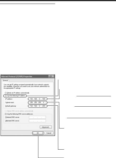
4.Set the IP address
 A Select [Use the following IP address].
 BSpecify the [IP address]. (For example, use 192.168.0.100)
Memo:
Make sure that you take note of the original IP address before altering.
Note:
Ensure that a duplicate IP address is not specified within the same network environment.
CSet [Subnet Mask] to a value that is appropriate for the setting operation. Consult the network administrator if you have any queries. (Use 255.255.255.0 when the camera is in its default settings.)
DWhen a [Default Gateway] is present, make use of the corresponding IP address (e.g., 192.168.0.254).
EClick
5.Click [OK] on the ALocal Area Connection PropertiesB screen
7
Network Settings
IP Address Settings (continued)
Internet Explorer Setting
1.Launch the Internet Explorer on the computer
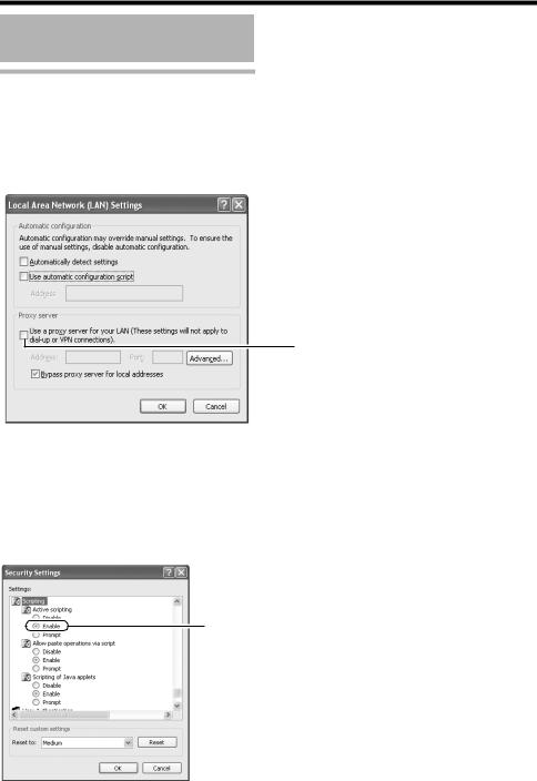
2.When proxy settings are enabled in the Internet Explorer, follow the steps below to disable the proxy of the Internet Explorer
●Select in the order of [Tool]-[Internet Options]-[Connections]-[LAN Setting], followed by deselecting the check for [Use a proxy server for your LAN] under [Proxy Server] of the [Local Area Network (LAN) Settings] window.
Deselect the check
3. If the active script of the Internet Explorer is disabled, follow the steps below to enable it
●Select [Trusted sites] under [Tool]-[Internet Options]-[Security]. Upon doing so, the [Sites…] button directly below becomes active. Click this button and deselect the check in the displayed window, and add the following web site to the zone.
http://192.168.0.2
●Next, select [Trusted sites] under [Tool]-[Internet Options]-[Security], and press the [Custom Level] button. Select [Enable] under [Scripting]-[Alarm] of the [Security Settings] window that has been opened.
Select [Enable]
8
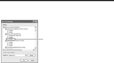
4.If ActiveX controls and plug-ins of the Internet Explorer is disabled, follow the steps below to enable it
●Click [Trusted sites] under [Tool]-[Internet Options]-[Security]. Select the [Custom Level] button and open the [Security Settings] window. Set all items under [ActiveX controls and plug-ins] in the opened window to [Enable]. Enable also [Allow Script-initiated window without size or position constraints.] under [Miscellaneous].
Select [Enable]
5.Disable pop-up block
Connection of camera cannot be established when pop-up block in the Internet Explorer is set to AEnableB.
Follow the steps below to set the pop-up block to AdisableB.
●Selecting [Tool]-[Pop-up Blocker]-[Turn Off Pop-up Blocker] permits all sites.
●To allow only specific sites such as camera, select [Tool]-[Pop-up Blocker]-[Turn On Pop-up Blocker], followed by selecting [Tool]-[Pop-up Blocker]-[Pop-up Blocker Settings] that becomes active to open the [Pop-up Blocker Settings] window.
In the opened window, add the address of camera as a permitted web site address.
6.When plug-in tools such as the Yahoo or Google toolbar are included in the Internet Explorer, disable the pop-up block function of these plug-in tools as well
9
Network Settings
IP Address Settings (continued)
Connecting the camera to the computer
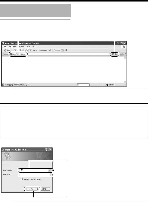
1.Launch the Internet Explorer
A Enter the following IP address into the address field. |
B Click [Go]. |
||
|
http://192.168.0.2 |
|
|
|
|
|
|
|
|
|
|
Memo:
●If the proxy server settings for access to the Internet via the Internet Explorer is enabled, you may not be able to specify the IP address directly. In this case, change the proxy settings of the Internet Explorer.
When the IP address of the camera is unknown
IP address settings cannot be changed by accessing via a computer when the IP address of the camera is unknown. You can use the following method to identify the IP address.
●Search for the camera in the LAN using [Search tool] inside [Tool_E] folder of the supplied CDROM.
TFor details on [Search tool], please refer to the AReadmeB file in the CD-ROM supplied with this product.
2.Enter the user name and password (login as administrator) (A Page 14)
A Enter the user name.
This is set to AadminB by default.
 B Enter the password.
This is set to AjvcB by default.
C Click [OK].
Memo:
● After the [Security Settings] screen appears, press the [OK] button to proceed.
10
3.Built-in Viewer of camera is displayed
4.The operator password entry screen appears
A
B
AEnter the password (default is AjvcB) of AoperatorB authority.
BClick [OK].
Memo:
●The operator password entry screen does not appear if the password is stored on the computer. Proceed to configure the IP address setting for the camera. (A Page 12)
11
Network Settings
IP Address Settings (continued)
IP address setting for the camera
1 Click [Details] of the camera Built-in viewer

 Click
Click
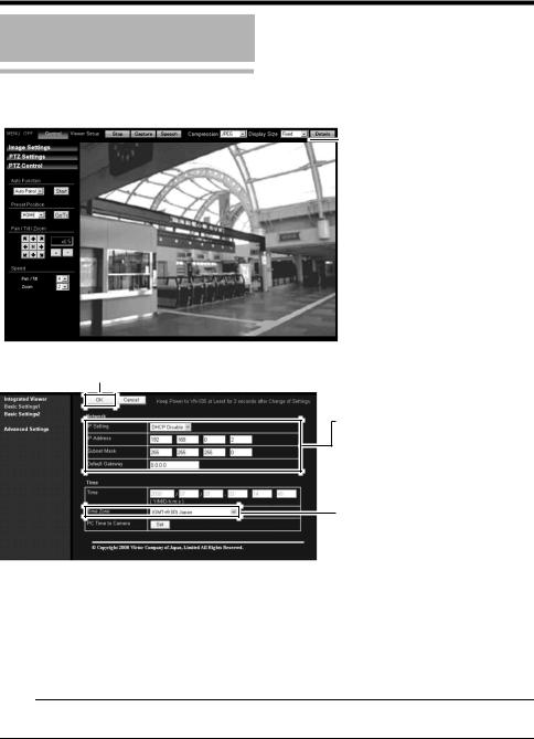
2 The [Basic Settings1] screen appears
CClick
A Set the [IP Setting] item to [DHCP Disable].
Enter the values you wish to specify in the [IP Address], [Subnet Mask] and [Default Gateway] fields.
B Select the [Time Zone].
A Set the [IP Setting].
●When selecting ADHCP DisableB:
Select ADHCP DisableB, and specify a value in the [IP Address], [Subnet Mask] and [Default Gateway] fields.
●When selecting ADHCP EnableB:
The default setting is ADHCP DisableB (DHCP client function is Disabled). To assign an IP address from the DHCP server, connect the DHCP server to the LAN, set the AIP SettingB of the camera to ADHCP EnableB, and click the [OK] button. For details on IP addresses assigned to the camera, consult your network administrator.
Note:
●Set the DHCP server such that the same IP address is always assigned to the MAC address of the camera by the DHCP server. Connection may fail if the above setting is not performed.
12

B Select the [Time Zone].
C Click [OK].
3 A confirmation screen appears
Click [OK].
Camera restarts using the new IP address. It takes about one minute for the camera to reboot.
Memo:
●Access from the connected computer may fail when the IP address of the camera is changed. To enable access to camera from the same computer, alter the IP address at the computer accordingly.
When the display or configuration of the opened screen appears strange, check using the following procedures.
AClick [Start]-[Control Panel]-[Display] and open the [Display Properties] window
BClick the [Settings] tab in the [Display Properties] windows and click the [Advanced] button
CCheck that [DPI setting] in the [General] tab has become [Normal size (96DPI)]
DOtherwise, change the setting to [Normal size (96DPI)] and reboot windows
13

Network Settings
Enter user name and password
User name and password entry will be required at the beginning.
There are three access authorization levels to camera. The factory settings are as follows.
User |
Default |
Authorization |
Name |
Password |
levels |
|
|
|
admin |
jvc |
All operations and |
|
|
setting changes are |
|
|
allowed |
|
|
|
operator |
jvc |
Change of settings |
|
|
other than those |
|
|
related to network |
|
|
and maintenance |
|
|
are allowed |
|
|
|
user |
jvc |
Viewing of images |
|
|
is allowed |
|
|
|
Pages that users have access to
Restrictions are placed on the pages that users have access to. In addition, links on the web pages are also displayed according to the access authority of the user.
● admin
(TX) is applicable to VN-X series only.
Basic Settings1 |
[Network] |
|
[Time] |
|
|
Basic Settings2 |
[Camera] |
|
[Encoding] |
|
[JPEG] |
|
[MPEG4] |
|
|
Details |
[Camera] |
|
[Encoding] |
|
[Audio] (This feature is not |
|
available in VN-V25U) |
|
[Alarm] |
|
[Alarm Environment] |
|
[PTZ] (TX) |
|
[Auto Patrol] (TX) |
|
[Privacy Mask] |
|
[Motion detection] |
|
[Network Basic] |
|
[Network Details] |
|
[Protocol] |
|
[Streaming] |
|
[Access Restrictions] |
|
[Time] |
|
[Password] |
|
[Maintenance] |
|
[LED Settings] |
|
[Miscellaneous] |
|
[Operation] |
|
[Settings] |
|
[Position List] (TX) |
|
[Patrol Settings] (TX) |
|
|
14

● operator
(TX) is applicable to VN-X series only.
Basic Settings2 |
[Camera] |
|
[Encoding] |
|
[JPEG] |
|
[MPEG4] |
|
|
Details |
[Camera] |
|
[Encoding] |
|
[Audio] (This feature is not |
|
available in VN-V25U) |
|
[Alarm] |
|
[Alarm Environment] |
|
[PTZ] (TX) |
|
[Auto Patrol] (TX) |
|
[Privacy Mask] |
|
[Motion detection] |
|
[Streaming] |
|
[LED Settings] |
|
[Miscellaneous] |
|
[Operation] |
|
[Settings] |
|
[Position List] (TX) |
|
[Patrol Settings] (TX) |
|
|
● user |
|
|
|
Details |
[Miscellaneous] |
|
|
Memo:
●The [Security Settings] screen appears before the top page is displayed. Press the [Yes] button to proceed.
If you do not want this warning screen to be displayed, change the Internet Explorer settings as follows.
●Open [Tool]-[Internet Options]-[Security] and select the [Trusted sites] icon.
●Next, press the [Custom Level] button, followed by selecting AEnableB for [Miscellaneous]-[Display mixed content].
Note:
●Do not reset or turn off the power of camera immediately after the settings are changed. Otherwise, changes may not be saved, and camera may be restored to the factory settings.
15

Setting Using Internet Explorer
Setting
How to open the setting page
1.Enter IP address of camera in the address bar of Internet Explorer (A Page 10)
A unified viewer is opened.
Click |
2.Click [Details].
●[Basic Settings1] page will be opened if accessed by user name AadminB. (A Page 17)
●[Basic Settings2] page will be opened if accessed by user name AoperatorB. (A Page 18)
●[Miscellaneous] page will be opened if accessed by user name AuserB. (A Page 59)
16

Basic Settings1
This page is for performing basic setting related to the network.
This page can be used during access using AadminB.
●Click [Basic Settings1].
●Press the [OK] button to enable the new settings.
●If the [OK] button is pressed upon entering an invalid value, a warning message will appear and the entry will be denied. Press the [Cancel] button to restore the invalid entry to the current value.
Click
A
B
C
D
E
F
Memo:
● You can open the [Basic Settings1] screen without going through the built-in viewer by entering the following URL address ( 
 contains model name) in the address field of Internet Explorer.
● Enter the model name in lowercase letters.
Example VNV225U series is displayed :
http://192.168.0.2/cgi-bin/ v225
v225 display.cgi?
 v225
v225 basicmenu1.html
Network |
|
A IP Setting |
For setting the DHCP client function. |
|
Connect camera to a network environment with a DHCP |
|
server when DHCP is to be enabled. If the DHCP server does |
|
not exist when [IP Setting] is set to ADHCP EnableB, camera |
|
will start running with the 192.168.0.2 IP address and |
|
255.255.255.0 subnet mask in about 2 minutes after startup. |
|
(A Page 6) |
B IP Address |
For setting the IP address of camera. |
C Subnet Mask |
For setting the subnet mask of camera. |
D Default Gateway |
For setting the default gateway of camera. |
|
Enter 0.0.0.0 if you do not want to set a default gateway. |
Time |
|
E Time |
Displays the clock time of camera. |
|
The time transmitted by camera is recorded in the JPEG |
|
header. Discontinuity may occur in the JPEG header's time |
|
immediately before and after changing the time. |
F Time Zone |
For setting the time zone. |
G PC Time to Camera |
Click the [Set] button to set the time of the computer on |
|
camera. |
17
Setting Using Internet Explorer
Setting (continued)
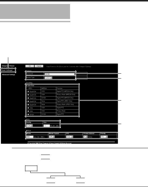
Basic Settings2
Page for setting fundamental parameters of ACameraB, AJPEGB and AMPEG4B. This page can be used during access using AadminB or AoperatorB.
●Click [Basic Settings2].
●Press the [OK] button to enable the new settings.
●If the [OK] button is pressed upon entering an invalid value, a warning message will appear and the entry will be denied. Press the [Cancel] button to restore the invalid entry to the current value.
Click
A
B
C
D

 E
E
Memo:
● You can open the [Basic Settings2] screen without going through the built-in viewer by entering the following URL address ( 
 contains model name) in the address field of Internet Explorer.
● Enter the model name in lowercase letters.
Example VNV225U series is displayed :
http://192.168.0.2/cgi-bin/ v225
v225 display.cgi?
 v225
v225 basicmenu2.html
18

(TV) is applicable to VN-V series only. (TX) is applicable to VN-X series only.
A Camera ID |
Character strings entered here will be written to the JPEG comment segment |
|
||
|
(item name: camera). Refer to the API Guide on the file formats of JPEG. |
|
||
|
|
|
||
B Monitor Type |
For selecting the monitor type according to the monitor used to display the |
|
||
|
video images. The picture quality varies according to the type of monitor |
|
||
|
selected. |
|
|
|
|
Custom |
: Enables setting of picture quality according to the user's |
|
|
|
|
|
preference. Detailed settings are configured on the detailed |
|
|
|
|
settings page of the camera. (A Page 21) |
|
|
LCD1,LCD2 |
: Picture quality setting for LCD monitors. Two types are |
|
|
|
|
|
available for selection according to the user's preference. |
|
|
CRT |
: Picture quality setting for CRT (cathode-ray tube) monitors. |
|
|
|
[Set values: Custom, LCD1, LCD2,CRT] |
|
||
|
|
|
||
C Encoding |
For selecting the frame size for each of the JPEG and MPEG4 screens from |
|
||
|
AQuad VGAB |
(1280 x 960)(TX), AVGAB(640 x 480), and AQVGAB (320 x 240). |
|
|
|
Select one of the four (TV) or eight (TX) different patterns. |
|
||
|
Memo: |
|
|
|
|
|
|
|
|
|
● Refer to the API Guide on the file formats of JPEG. |
|
||
|
|
|
|
|
Combination of distribution sizes and available features of VN-V series
|
Distribution Size |
|
Feature |
|
|
|
|
|
|
|
JPEG |
MPEG4 |
|
Privacy Mask |
|
|
|
|
|
1 |
QVGA |
QVGA |
|
JPEG/MPEG4 |
|
|
|
|
|
2 |
QVGA |
VGA |
|
JPEG only |
|
|
|
|
|
3 |
VGA |
QVGA |
|
MPEG4 only |
|
|
|
|
|
4 |
VGA |
VGA |
|
JPEG/MPEG4 |
|
|
|
|
|
Combination of distribution sizes and available features of VN-X series
|
Distribution Size |
|
Feature |
||
|
|
|
|
|
|
|
JPEG |
MPEG4 |
|
Digital PTZ |
Privacy Mask |
|
|
|
|
|
|
1 |
QuadVGA |
VGA |
|
MPEG4 only |
|
|
|
|
|
|
|
2 |
QuadVGA |
VGA |
|
|
MPEG4 only |
|
|
|
|
|
|
3 |
QuadVGA |
QVGA |
|
MPEG4 only |
|
|
|
|
|
|
|
4 |
QuadVGA |
T |
|
JPEG only |
|
|
|
|
|
|
|
5 |
QuadVGA |
T |
|
|
JPEG only |
|
|
|
|
|
|
6 |
VGA |
VGA |
|
JPEG/MPEG4 |
|
|
|
|
|
|
|
7 |
VGA |
VGA |
|
|
JPEG/MPEG4 |
|
|
|
|
|
|
8 |
QVGA |
QVGA |
|
JPEG/MPEG4 |
|
|
|
|
|
|
|
T Images are not distributed. It is displayed in white on viewer.
19

Setting Using Internet Explorer
Setting (continued)
Basic Settings2 (continued)
(TV) is applicable to VN-V series only. (TX) is applicable to VN-X series only.
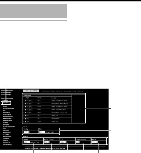
DJPEG
Frame Size |
For specifying the JPEG picture quality (rate control mode) and size (target file |
|
size). When AVFS1B to AVFS7B is selected, the quantization table during JPEG |
|
encoding will be maintained and the file size will increase/decrease according to |
|
the input signals. |
|
Typical sizes will be displayed in the Size field. When recording JPEG data to a |
|
recorder with a limited storage capacity, the maximum recording time may vary |
|
as the file size fluctuates under this setting. |
|
When AAFSB is selected, encoding is performed such that the target file size is |
|
the average size of multiple JPEG images. |
|
You can enter the target size in the Size field. |
|
[Picture quality values : VFS1 to VFS7, AFS] |
Memo:
● The picture size can be specified only when the picture quality value is set to AFS.
[Size setting range in Quad VGA mode 40 KB to 200 KB ] (TX)
[Size setting range in VGA mode 10 KB to 100 KB ] [Size setting range in QVGA mode 3 KB to 33 KB ]
EMPEG4
|
Bitrate |
For setting the MPEG4 encoding bit rate. |
|
|
|
[Set values : 64 kbps to 8000 kbps] |
|
|
|
|
|
|
Bitrate Control |
For selecting whether to set the MPEG4 rate control mode to CBR (Constant Bit |
|
|
|
Rate) or VBR (Variable Bit Rate). |
|
|
|
CBR |
: Encoding is performed at a fixed bit rate regardless of the condition of |
|
|
|
the input video signals. Enables easy forecast of the bit rate. |
|
|
VBR |
: Changes the bit rate according to the condition of the input video |
|
|
|
signals. Picture quality is stable, but forecast of the bit rate is difficult. |
|
|
|
|
|
FPS |
For setting the MPEG4 frame rate. |
|
|
|
[Set values : 1 fps, 7.5 fps, 10 fps, 15 fps, 30 fps (TV)] |
|
|
|
|
|
|
I Frame Interval |
For setting the I-frame interval. MPEG4 starts encoding from the I-frame. |
|
|
|
Shortening the interval stabilizes the picture quality even when there are rapid |
|
|
|
changes in the video image. However, the picture quality for images with little |
|
|
|
change will deteriorate. In addition, when multicast packet loss occurs, the time |
|
|
|
interval required to restore the image is shorter. |
|
|
|
[Set values : 15, 30, 45, 60, 75] |
|
|
|
|
|
|
Priority |
For selecting whether to assign priority to the frame rate or picture quality during |
|
|
|
MPEG4 encoding. |
|
|
|
FPS |
: Assigns priority to frame rate. Select this setting to enable smooth |
|
|
|
monitoring of motion images. |
|
|
Quality |
: Assigns priority to picture quality. |
|
|
|
|
20
Camera Page
This page is for setting the camera’s parameters.
This page can be used during access using AadminB or AoperatorB.
●Click [Advanced Settings] to display setting menu.
●Click [Camera].
●Press the [OK] button to enable the new settings.
●If the [OK] button is pressed upon entering an invalid value, a warning message will appear and the entry will be denied. Press the [Cancel] button to restore the invalid entry to the current value.
To restore the settings of this page to the factory settings, press [Initialize] button.
Click
A
B
C
D
E
F
G
H
I
J
K
L
M
N
O
21

Setting Using Internet Explorer
Setting (continued)
(TV) is applicable to VN-V series only. (TX) is applicable to VN-X series only.
A Camera ID |
|
Character strings entered here will be written to the JPEG comment segment |
|||||
|
|
(item name: camera). Refer to the API Guide on the file formats of JPEG. |
|||||
|
|
|
|||||
B Monitor Type |
|
For selecting the monitor type according to the monitor used to display the |
|||||
|
|
video images. The picture quality varies according to the type of monitor |
|||||
|
|
selected. |
|
|
|||
|
|
Custom |
|
|
|
: Enables setting of picture quality according to the user’s |
|
|
|
|
|
|
|
preference. |
|
|
|
LCD1, LCD2 |
: Picture quality setting for LCD monitors. Two types are |
||||
|
|
|
|
|
|
available for selection according to the user’s preference. |
|
|
|
CRT |
|
|
|
: Picture quality setting for CRT (cathode-ray tube) monitors. |
|
|
|
[Set values: Custom, LCD1, LCD2, CRT] |
|||||
|
|
Memo: |
|
|
|
||
|
|
|
|
|
|||
|
|
● Select ACustomB if you want to set the Gamma and Enhance frequency |
|||||
|
|
values. |
|
|
|||
|
|
|
|
|
|||
|
|
|
|||||
C Black Level |
|
For adjusting the black level. Lowering the value darkens the video image. |
|||||
|
|
Increasing the value brightens the image. |
|||||
|
|
[Setting range: 0 to 2] |
|||||
|
|
Memo: |
|
|
|
||
|
|
|
|
|
|||
|
|
● If the black level is set to “0”, this may be too low depending on the |
|||||
|
|
monitoring device, or dark area will become complete black. |
|||||
|
|
● When using MPEG4 images, set to either “1” or “2”. |
|||||
|
|
|
|
||||
|
|
|
|||||
D Gamma |
|
To alter the appearance of dark areas in a video image, adjust the gamma |
|||||
|
|
curve. |
|
|
|
|
|
|
|
Off |
: Do not perform gamma correction. The entire image appears dull. |
||||
|
|
-3 to 3 : Perform gamma correction. When this is set to “0”, standard gamma |
|||||
|
|
|
|
|
correction is performed. Setting to a smaller value darkens the image, |
||
|
|
|
|
|
while increasing the value brightens the image. |
||
|
|
[Set values: Off, -3 to 0 to 3] |
|||||
|
|
Memo: |
|
|
|
||
|
|
|
|
|
|||
|
|
● The set value is fixed when the monitor type is set to ALCD1B, ALCD2B, or ACRTB. |
|||||
|
|
|
|
||||
|
|
|
|||||
E Enhance |
|
For setting the type of edge enhancement. |
|||||
Frequency |
|
Low |
: Enhances both thick and thin edges. |
||||
|
|
High |
: Enhances thin edges. |
||||
|
|
[Set values: Low, High] |
|||||
|
|
Memo: |
|
|
|
||
|
|
|
|
|
|||
|
|
● The set value is fixed when the monitor type is set to ALCD1B, ALCD2B, or ACRTB. |
|||||
|
|
|
|
||||
|
|
|
|||||
F Enhance Level |
|
For setting the intensity of edge enhancement. |
|||||
|
|
Larger value |
: Increases the intensity of edge enhancement. |
||||
|
|
Smaller value |
: Decreases the intensity of edge enhancement. |
||||
|
|
[Setting values: -5 to 0 to 5] |
|||||
|
|
|
|
|
|
|
|
22

(TV) is applicable to VN-V series only. (TX) is applicable to VN-X series only.
G Color Level |
|
For adjusting the color level. |
|
||
|
|
Larger value |
: Increases the color level. |
|
|
|
|
Smaller value |
: Decreases the color level. |
|
|
|
|
[Setting values: -5 to 0 to 5] |
|
||
|
|
|
|
||
H AGC |
|
For setting the AGC (automatic gain control) level. |
|
||
|
|
Off |
: Disables the AGC feature |
|
|
|
|
Mid |
: When the amount of light is insufficient |
|
|
|
|
High |
: When the amount of light is particularly insufficient |
|
|
|
|
Super |
: When the brightness level is insufficient even upon setting to |
|
|
|
|
|
High. |
|
|
|
|
[Set values: Off, Mid, High, Super] |
|
||
|
|
Memo: |
|
|
|
|
|
|
|
|
|
|
|
● This feature cannot be configured when the L Easy Day/Night feature is |
|
||
|
|
set to ABlack and WhiteB or AAutoB. |
|
||
|
|
● The AGC cannot be set when the L “B&W Mode” is set to “Black and |
|
||
|
|
White” or “Auto Low, Auto Mid or Auto High”. |
|
||
|
|
● The screen appears grainy at dark locations when the AGC feature is in |
|
||
|
|
use. |
|
|
|
|
|
|
|
||
|
|
|
|
||
I Sense Up |
|
This feature is used to raise the sensitivity level by lengthening the exposure |
|
||
|
|
time. |
|
|
|
|
|
You can specify the number of times by which the sensitivity level is to be |
|
||
|
|
increased automatically when the object becomes dark. When Ax16B is |
|
||
|
|
selected, the sensitivity level will automatically increases continuously until it |
|
||
|
|
is 16 times of the level when AOffB is selected. When the sensitivity level |
|
||
|
|
increases, the shutter speed slows down and motion becomes unnatural. |
|
||
|
|
When set to AOffB, [Sense Up] is disabled. |
|
||
|
|
[Set values: Off, x2(1/15s), x4(1/7.5s), x8(1/3.75s), x16(0.5s), |
|
||
|
|
|
x32(1.1s),x62(2.1s)] (TV) |
|
|
|
|
[Set values: Off, x2(1/7.5s), x4(1/3.75s), x8(0.5s), x16(1.1s), x22(1.5s)] (TX) |
|
||
|
|
Memo: |
|
|
|
|
|
|
|
|
|
|
|
● Upon raising the sensitivity level, the screen may appear grainy or white, |
|
||
|
|
or white defects may occur. However, this is not a malfunction. |
|
||
|
|
● When Sense Up is set to a value other than AOffB, flickers occur under |
|
||
|
|
the light of fluorescent or mercury lamps. This is not a malfunction of the |
|
||
|
|
camera, but is due to principles related to Sense Up. |
|
||
|
|
● When the shutter is set to a value between 1/250 to 1/10000, set |
|
||
|
|
Sense Up to AOffB. |
|
||
|
|
|
|
||
|
|
|
|
||
J ALC Priority |
|
For setting the priority of ALC (feature for maintaining the video level |
|
||
|
|
according to the brightness of the object). You can select whether to assign |
|
||
|
|
priority to the motion or picture quality when the object becomes dark. |
|
||
|
|
Motion |
: Assigns priority to motion. |
|
|
|
|
|
When the object becomes dark, priority is given to AGC |
|
|
|
|
|
(automatic gain control), and therefore this is suitable for |
|
|
|
|
|
shooting fast-moving objects. |
|
|
|
|
Quality |
: Assigns priority to picture quality. |
|
|
|
|
|
When the object becomes dark, priority is given to the Sense |
|
|
|
|
|
Up feature, and therefore this is suitable for shooting objects |
|
|
|
|
|
requiring a high picture quality. |
|
|
|
|
[Set values: Motion, Quality] |
|
||
|
|
|
|
|
|
23
Setting Using Internet Explorer
Setting (continued)
Camera Page (continued)
(TV) is applicable to VN-V series only. (TX) is applicable to VN-X series only.
K Shutter Speed |
|
For setting the shutter speed. |
|
|||
|
|
Auto, Auto(1/15 - 1/100) |
: Varies the shutter speed automatically according |
|
||
|
|
|
|
|
to the brightness. |
|
|
|
1/15 to 1/10000 |
|
: Fixed shutter speed. |
|
|
|
|
Flickerless |
|
: Reduces flickers due to fluorescent lamps. |
|
|
|
|
[Set values : Auto, Auto(1/15 - 1/100) (TX), 1/15 (TX), 1/25 (TX), 1/30, 1/50, |
|
|||
|
|
Memo: |
1/60, 1/100,1/250, 1/500,1/1000, 1/2000, 1/4000, 1/10000, Flickerless] |
|
||
|
|
|
|
|
|
|
|
|
|
|
|
|
|
|
|
● AAutoB is only recommended when using a manual iris lens. |
|
|||
|
|
● Flickers may occur when this is set to a value other than A1/50B, A1/100B, or |
|
|||
|
|
AFlickerlessB. When AFlickerlessB is selected, flickers may occur when the |
|
|||
|
|
Sense Up feature is used. |
|
|||
|
|
● When Sense Up is set to a value other than AOffB, the shutter speed cannot |
|
|||
|
|
be set to a value between 1/250 to 1/10000. |
|
|||
|
|
|
|
|||
|
|
|
|
|||
L Easy Day and |
|
For setting the Easy Day and Night feature. |
|
|||
Night |
|
Color |
: Sets to the color mode at all times. |
|
||
VN-V25U |
|
Black and White |
: Sets to the black-and-white mode at all times. |
|
||
VN-X35U only |
|
Auto |
: Image color switches to black-and-white when the |
|
||
|
|
|
|
luminance level is low. |
|
|
|
|
[Set values : Color, Black and White, Auto] |
|
|||
|
|
Memo: |
|
|
|
|
|
|
|
|
|
|
|
|
|
● The threshold of the Auto switching cannot be changed. |
|
|||
|
|
|
|
|||
|
|
|
|
|||
LB&W Mode |
|
For specifying whether to switch the image to the B&W mode. |
|
|||
VN-V26U |
|
Auto mode can be specified for switching automatically to the black-and white |
|
|||
VN-V225U series |
|
mode when the luminance level is low. In auto mode one of three levels can be |
|
|||
VN-X235U series |
|
selected according to the luminance level. |
|
|||
only |
|
Color |
: Switches to the color mode at all times. |
|
||
|
|
Black and White |
: Switches to the black-and-white mode at all times. |
|
||
|
|
Auto Low |
: Switches to the black-and-white mode when the luminance |
|
||
|
|
|
|
of the signal level of the object is low. |
|
|
|
|
Auto Mid |
: Switches to the black-and-white mode when the luminance |
|
||
|
|
|
|
of the signal level of the object is medium. |
|
|
|
|
Auto High |
: Switches to the black-and-white mode when the luminance |
|
||
|
|
|
|
of the signal level of the object is high. |
|
|
|
|
[Set values : Color, Black and White, Auto Low, Auto Mid, Auto High ] |
|
|||
|
|
Memo: |
|
|
|
|
|
|
|
|
|
|
|
|
|
● The infrared filter engages and disengages when switching between modes, |
|
|||
|
|
which causes mechanism noise. |
|
|||
|
|
● During the occurrence of mechanism noise, the distribution sound from the |
|
|||
|
|
camera will be muted. (VN-V26U only) |
|
|||
|
|
● When AAuto LowB, AAuto MidB or AAuto HighB has been selected, the |
|
|||
|
|
camera will change the mode immediately according to the luminance level. |
|
|||
|
|
|
|
|
|
|
|
|
|
|
|
|
|
24

(TV) is applicable to VN-V series only. (TX) is applicable to VN-X series only.
M EV |
For setting EV (Exposure Value) correction. Enables setting between -9(-3EV) to |
||
|
Compensation |
6(+2EV). You can specify settings in each 1/3 EV step. Decreasing the value |
|
|
|
|
darkens the images, while increasing the value brightens the image. |
|
|
|
[Set values: -9 to 0 to 6] |
|
|
|
|
N White Balance |
For selecting the white balance control feature. White balance can be adjusted |
||
|
|
|
for a light source with a color temperature range of 2800K to 9500K. |
|
|
|
|
|
ATW |
Switches to the Auto-Tracking White Balance (automatic color temperature |
|
|
|
|
tracking) mode. Adjusts the white balance automatically according to the color |
|
|
|
temperature of the light. |
|
|
|
|
|
AWC |
Switches to the Auto-White Balance Control mode. In the AWC mode, values |
|
|
|
|
entered for the [AWC R-GAIN] and [AWC B-GAIN] items are applied to white |
|
|
|
balance. |
|
|
|
|
|
|
One Push |
Executes AWC (automatic white balance control). |
|
|
AWC |
Execute by placing a white object around the center of the screen in a location |
|
|
|
|
|
|
|
with a lighting condition that is similar to the object to be shot. |
Memo:
●Pressing the [One Push] button replaces the [AWC R-GAIN] and [AWC B- GAIN] values with the values of the AWC execution results.
●Even when white balance is set to ATW, pressing the [One Push] button switches the mode automatically to AWC.
|
AWC R-Gain |
For setting the gain of R (red) when in the AWC mode. |
|
|
|
|
|
||||||||||||||||||||
|
|
Larger value |
: Increases the redness. |
|
|
|
|
|
|
|
|
|
|||||||||||||||
|
|
Smaller value |
: Decreases the redness. |
|
|
|
|
|
|
|
|
|
|||||||||||||||
|
|
[Set values: 0 to 85 to 255] |
|
|
|
|
|
|
|
|
|
|
|
|
|
|
|
||||||||||
|
|
|
|
|
|
|
|
|
|
|
|
|
|
|
|
|
|
|
|
|
|
|
|
||||
|
AWC B-Gain |
For setting the gain of B (blue) when in the AWC mode |
|
|
|
|
|
||||||||||||||||||||
|
|
Larger value |
: Increases the blueness. |
|
|
|
|
|
|
|
|
|
|||||||||||||||
|
|
Smaller value |
: Decreases the blueness. |
|
|
|
|
|
|
|
|
|
|||||||||||||||
|
|
[Set values: 0 to 219 to 255] |
|
|
|
|
|
|
|
|
|
|
|
|
|
|
|
||||||||||
|
|
|
|
|
|
|
|
|
|
|
|
|
|
|
|
|
|
|
|
|
|
||||||
O Back Light |
For selecting the backlight compensation feature. Set this feature when there |
|
|||||||||||||||||||||||||
Compensation |
is a bright light source in the same direction as the object. Enables unwanted |
|
|||||||||||||||||||||||||
|
|
light sources to be excluded from the photometry area. |
|
|
|
|
|
||||||||||||||||||||
|
|
Off |
: Disables backlight compensation. |
|
|
|
|
|
|||||||||||||||||||
|
|
Area1 to 4 |
: For selecting a photometry area from the four available |
|
|||||||||||||||||||||||
|
|
|
|
|
|
|
types. |
|
|
|
|
|
|
|
|
|
|
|
|
|
|
|
|||||
|
|
[Set values: Off, Area1, Area2, Area3, Area4] |
|
|
|
|
|
||||||||||||||||||||
|
|
Photometry |
Photometry |
Photometry |
Photometry |
Photometry |
|
||||||||||||||||||||
|
|
|
Area |
|
|
Area |
|
|
Area |
|
Area |
|
Area |
|
|||||||||||||
|
|
|
|
|
|
|
|
|
|
|
|
|
|
|
|
|
|
|
|
|
|
|
|
|
|
|
|
|
|
|
|
|
|
|
|
|
|
|
|
|
|
|
|
|
|
|
|
|
|
|
|
|
|
|
|
|
|
|
|
|
|
|
|
|
|
|
|
|
|
|
|
|
|
|
|
|
|
|
|
|
|
|
|
|
|
|
|
|
|
|
|
|
|
|
|
|
|
|
|
|
|
|
|
|
|
|
|
|
|
|
|
|
|
|
|
|
|
|
|
|
|
|
|
|
|
|
|
|
|
|
|
|
|
|
|
|
|
|
|
|
|
|
|
|
|
|
|
|
|
|
|
|
|
|
|
|
|
|
|
|
|
|
|
|
|
|
|
|
|
|
Off |
|
|
Area1 |
|
|
Area2 |
|
|
Area3 |
|
|
Area4 |
|
|
||||||||||
|
|
Memo: |
|
|
|
|
|
|
|
|
|
|
|
|
|
|
|
|
|
|
|
|
|
|
|
||
|
|
|
|
|
|
|
|
|
|
|
|
|
|
|
|
|
|
|
|
|
|
|
|
|
|||
|
|
● The backlight compensation area is not linked to digital PTZ (TX). |
|
||||||||||||||||||||||||
|
|
|
|
|
|
|
|
|
|
|
|
|
|
|
|
|
|
|
|
|
|
|
|
|
|
|
|
25
Setting Using Internet Explorer
Setting (continued)
Encoding Page
This page is for setting JPEG and MPEG4 encoding parameters.
This page can be used during access using AadminB or AoperatorB.
●Click [Advanced Settings] to display setting menu.
●Click [Encoding].
●Press the [OK] button to enable the new settings.
●If the [OK] button is pressed upon entering an invalid value, a warning message will appear and the entry will be denied. Press the [Cancel] button to restore the invalid entry to the current value.
●When settings on this page are altered during playback using the built-in viewer, reboot the viewer.
●There is upper limit to transmission bit rate from the camera. If a bit rate that exceeds upper limit is
specified, this new setting will not be applied. For details on the maximum transmission limit, refer to the section on ANetwork RequirementsB (A Page 3).
Click
A
B
C D E F G
26
Loading...