


DVD/CD PLAYER
Hi-Fi STEREO
VIDEO CASSETTE
RECORDER
USER'S GUIDE
For model:
HR-XVC1U
TV |
VCR |
DVD |
POWER |
DVD MENU |
MARKER |
RETURN |
|
DISPLAY |
A.TRK |
C.RESET |
ZERO RETURN |
|
SUB TITLE |
ANGLE |
|
SP/EP |
|
|
|
|
ZOOM |
TITLE |
|
|
|
|
TV |
|
|
|
POWER |
|
|
|
INPUT |
|
|
|
TV VOL |
0 |
TIMER |
TV/VCR |
|
REW
PLAY
 FF
FF
REC
SKIP /INDEX
STOP
TV/VCR CH+
PAUSE
SKIP /INDEX
SET
SET UP MENU
OSD
ENTER/
SELECT
TV/VCRCH– SLOW
A.MONITOR
SET
CANCEL
SKIP SEARCH
VCR/DVD/TV
For Customer Use:
Enter below the Model No. and Serial No. which are located on the rear of cabinet. Retain this information for future reference.
Model No.
Serial No.
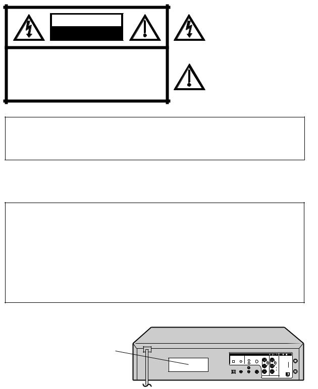
CAUTION
RISK OF ELECTRIC SHOCK
DO NOT OPEN
CAUTION: TO REDUCE THE RISK OF ELECTRIC SHOCK, DO NOT REMOVE COVER (OR BACK). NO USER-SERVICEABLE PARTS INSIDE. REFER SERVICING TO QUALIFIED SERVICE PERSONNEL.
The lightning flash with arrowhead symbol, within an equilateral triangle is intended to alert the user to the presence of uninsulated dangerous voltage within the product's enclosure that may be of sufficient magnitude to constitute a risk of electric shock to persons.
The exclamation point within an equilateral triangle is intended to alert the user to the presence of important operating and maintenance (servicing) instructions in the literature accompanying the appliance.
WARNING: TO REDUCE THE RISK OF FIRE OR ELECTRIC SHOCK, DO NOT EXPOSE THIS APPLIANCE TO RAIN OR MOISTURE.
CAUTION: TO PREVENT ELECTRIC SHOCK DO NOT USE THIS POLARIZED PLUG WITH AN EXTENSION CORD, RECEPTACLE OR OTHER OUTLET UNLESS THE BLADES CAN BE FULLY INSERTED TO PREVENT BLADE EXPOSURE.
CAUTION: Changes or modifications not expressly approved by the partly responsible for compliance with the FCC Rules could void the user's authority to operate this equipment.
CAUTION:
THIS DIGITAL VIDEO PLAYER EMPLOYS A LASER SYSTEM.
TO ENSURE PROPER USE OF THIS PRODUCT, PLEASE READ THIS USER'S GUIDE CAREFULLY AND RETAIN FOR FUTURE REFERENCE. SHOULD THE UNIT REQUIRE MAINTENANCE, CONTACT A JVC AUTHORIZED SERVICE CENTER.
USE OF CONTROLS, ADJUSTMENTS OR THE PERFORMANCE OF PROCEDURES OTHER THAN THOSE SPECIFIED HEREIN MAY RESULT IN HAZARDOUS RADIATION EXPOSURE.
TO PREVENT DIRECT EXPOSURE TO LASER BEAM, DO NOT TRY TO OPEN THE ENCLOSURE. VISIBLE LASER RADIATION MAY BE PRESENT WHEN THE ENCLOSURE IS OPENED. DO NOT STARE INTO BEAM.
Location of the required Marking
The rating sheet and the safety caution are on the rear of the unit.
CERTIFICATION: COMPLIES WITH FDA RADIATION PERFORMANCE STANDARDS, 21 CFR SUBCHAPTER J.
DVD OUTPUT
DIGITAL AUDIO |
AUDIO |
S-VIDEO COMPONENT |
|
|
IN |
|
OPTICAL |
COAXIAL |
L |
Y |
VIDEO |
|
|
|
|
|
(ANT.) |
|||
|
|
R |
|
|
|
|
|
|
|
PB/CB |
L |
|
|
|
|
|
|
AUDIO |
|
OUT |
|
|
|
PR/CR |
R |
|
( TV) |
|
|
|
CH. |
|
||
|
|
|
|
|
|
|
|
|
|
|
|
3 |
4 |
2

IMPORTANT SAFEGUARDS
1.READ INSTRUCTIONS
All the safety and operating instructions should be read before the unit is operated.
2.RETAIN INSTRUCTIONS
The safety and operating instructions should be retained for future reference.
3.HEED WARNINGS
All warnings on the unit and in the operating instructions should be adhered to.
4.FOLLOW INSTRUCTIONS
All operating and use instructions should be followed.
5.CLEANING
Unplug this unit from the wall outlet before cleaning. Do not use liquid cleaners or aerosol cleaners. Use a damp cloth for cleaning the exterior cabinet only.
6.ATTACHMENTS
The manufacturer of this unit does not make any recommendations for attachments, as they may cause hazards.
7.WATER AND MOISTURE
Do not use this unit near water. For example, near a bathtub, washbowl, kitchen sink, laundry tub, in a wet
basement, or near a swimming pool.
8.ACCESSORIES
Do not place this unit on an unstable cart, stand, tripod, bracket, or table. The unit may fall, causing serious injury, and serious damage to the unit. An appliance and cart combination should be moved with care. Quick stops, excessive force, and uneven surfaces may cause the appliance and cart combination to overturn.
9.VENTILATION
PORTABLE CART WARNING (symbol provided by RETAC)
Slots and openings in the cabinet back or bottom are provided for ventilation, to ensure reliable operation of the unit, and to protect it from overheating.
These openings must not be blocked or covered. The openings should never be blocked by placing the unit on a bed, sofa, rug, or other similar surface. This unit should never be placed near or over a radiator or heat source. This unit should not be placed in a built-in installation such as a bookcase or rack unless proper ventilation is provided and/or the manufacturer’s instructions have been adhered to.
10.POWER SOURCES
This unit should be operated only from the type of power source indicated on the rating plate. If you are not sure of the type of power supply to your home, consult your appliance dealer or local power company. For units intended to operate from battery power, or other sources, refer to the operating instructions.
11.GROUNDING OR POLARIZATION
This unit is equipped with a polarized alternating-current line plug (a plug having one blade wider than the other). This plug will fit into the power outlet only one way. This is a safety feature. If you are unable to insert the plug fully into the outlet, try reversing the plug. If the plug should still fail to fit, contact your electrician to replace your obsolete outlet. Do not defeat the safety purpose of the polarized plug, if your unit is equipped with a 3-wire grounding-type plug, a plug having a third (grounding) pin. This plug will only fit into a ground- ing-type power outlet. This too, is a safety feature. If you are unable to insert the plug into the outlet, contact your electrician to replace your obsolete outlet. Do not defeat the safety purpose of the groundingtype plug.
12.POWER-CORD PROTECTION
Power-supply cords should be routed so that they are not likely to be walked on or pinched by items placed upon or against them, paying particular attention to cords at plugs, convenience receptacles, and the point where they exit from the appliance.
3

IMPORTANT SAFEGUARDS
13.LIGHTNING
To protect your unit from a lightning storm, or when it is left unattended and unused for long periods of time, unplug it from the wall outlet and disconnect the antenna or cable system. This will prevent damage to the unit due to lightning and power line surges.
14.POWER LINES
An outside antenna system should not be located in the vicinity of overhead power lines or other electric light or power circuits, or where it can fall into such power lines or circuits. When installing an outside antenna system, extreme care should be taken to keep from touching such power lines or circuits, as contact with them might be fatal.
15.OVERLOADING
Do not overload wall outlets and extension cords, as this can result in a risk of fire or electric shock.
16.OBJECT AND LIQUID ENTRY
Do not push objects through any openings in this unit, as they may touch dangerous voltage points or short out parts that could result in fire or electric shock. Never spill or spray any type of liquid into the unit.
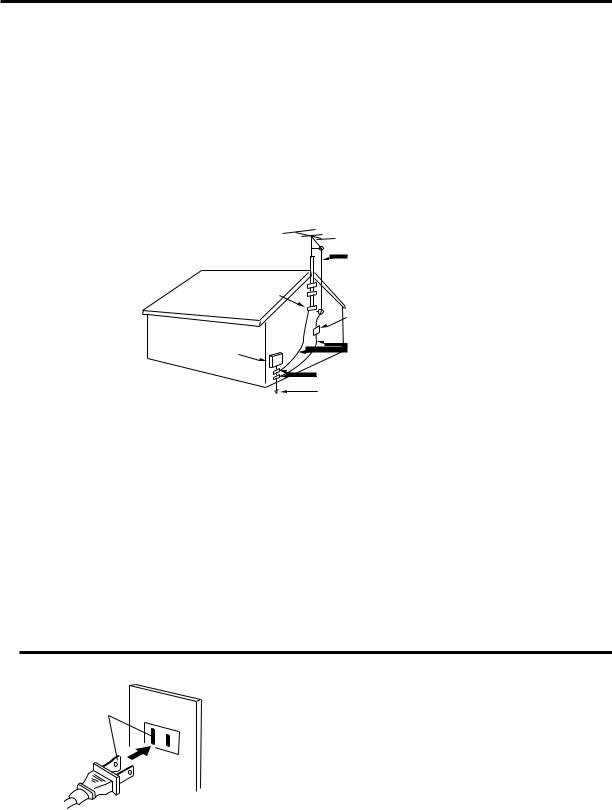
17.OUTDOOR ANTENNA GROUNDING
If an outside antenna or cable system is connected to the unit, be sure the antenna or cable system is grounded to provide some protection against voltage surges and built-up static charges, Section 810 of the National Electrical Code, ANSI/NFPA 70, provides information with respect to proper grounding of the mast and supporting structure, grounding of the lead-in wire to an antenna discharge unit, size of grounding conductors, location of antenna discharge unit, connection to grounding electrodes, and requirements for the grounding electrode.
18.SERVICING
Do not attempt to service this unit yourself as opening or removing covers may expose you to dangerous voltage or other hazards. Refer all servicing to qualified service personnel.
19.DAMAGE REQUIRING SERVICE
Unplug this unit from the wall outlet and refer servicing to qualified service personnel under the following conditions:
a.When the power-supply cord or plug is damaged.
b.If liquid has been spilled, or objects have fallen into the unit.
c.If the unit has been exposed to rain or water.
d.If the unit does not operate normally by following the operating instructions. Adjust only those controls that are covered by the operating instructions, as an improper adjustment of other controls may result in damage and will often require extensive work by a qualified technician to restore the unit to its normal operation.
e.If the unit has been dropped or the cabinet has been damaged.
f . When the unit exhibits a distinct change in performance, this indicates a need for service.
20.REPLACEMENT PARTS
When replacement parts are required, be sure the service technician uses replacement parts specified by the manufacturer or those that have the same characteristics as the original part.
Unauthorized substitutions may result in fire, electric shock or other hazards.
21.SAFETY CHECK
Upon completion of any service or repairs to this unit, ask the service technician to perform safety checks to determine that the unit is in proper operating condition.
22.HEAT
The product should be situated away from heat sources such as radiators, heat registers, stoves, or other products (including amplifiers) that produce heat.
23.DISC TRAY
Keep your fingers away from the disc tray as it is closing. It may cause serious personal injury.
24.CONNECTING
When you connect the product to other equipment, turn off the power and unplug all of the equipment from the wall outlet. Failure to do so may cause an electric shock and serious personal injury. Read the owner's manual of the other equipment carefully and follow the instructions when making any connections.
4
IMPORTANT SAFEGUARDS / Power Source
25.LASER BEAM
Do not look into the opening of the disc tray or ventilation opening of the product to see the source of the laser beam. It may cause sight damage.
26.DISC
Do not use a cracked, deformed, or repaired disc. These discs are easily broken and may cause serious personal injury and product malfunction.
27.NOTE TO CATV SYSTEM INSTALLER
This reminder is provided to call the CATV system installer’s attention to Article 820-40 of the NEC that provides guidelines for proper grounding and, in particular, specifies that the cable ground shall be connected to the grounding system of the building, as close to the point of cable entry as practical.
EXAMPLE OF ANTENNA GROUNDING AS PER THE
NATIONAL ELECTRICAL CODE
|
ANTENNA LEAD IN WIRE |
|
GROUND CLAMP |
ANTENNA |
|
DISCHARGE UNIT |
||
|
||
|
(NEC SECTION 810-20) |
|
ELECTRIC SERVICE |
GROUNDING CONDUCTORS |
|
EQUIPMENT |
||
(NEC SECTION 810-21) |
||
|
GROUND CLAMPS
POWER SERVICE GROUNDING
NEC-NATIONAL ELECTRICAL CODE ELECTRODE SYSTEM
(NEC ART 250, PART H)
S2898A
CONDENSATION
Moisture will form in the operating section of the DVD/VCR if the player is brought from cool surroundings into a warm room or if the temperature of the room rises suddenly. And when this happens, DVD/VCR's performance will be impaired.
To prevent this, let the DVD/VCR stand in its new surroundings for about an hour before switching it on, or make sure that the room temperature rises gradually.
Condensation may also form during the summer if the DVD/VCR is exposed to the breeze from an air conditioner. In such cases, change the location of the DVD/VCR.
Power Source
AC Outlet
Wider Hole
and Blade
Polarized AC Cord Plug
(One blade is wider than the other.)
TO USE AC POWER SOURCE
Use the AC polarized line cord provided for operation on AC. Insert the AC cord plug into a standard 120V 60Hz polarized AC outlet.
NOTES:
•Never connect the AC line cord plug to other than the specified voltage (120V 60Hz). Use the attached power cord only.
•If the polarized AC cord does not fit into a non-polarized AC outlet, do not attempt to file or cut the blade. It is the user’s responsibility to have an electrician replace the obsolete outlet.
•If you cause a static discharge when touching the unit and the unit fails to function, simply unplug the unit from the AC outlet and plug it back in. The unit should return to normal operation.
5

Features
DVD/CD Player/Video Cassette Recorder
•DVD/CD player with Video Cassette Recorder - Unique space saving design combines a DVD/CD player and a Hi-Fi Video cassette recorder. The DVD disc has much more capacity, but is the same size as the audio CD disc. Picture quality is higher
than Super VHS. Audio quality is higher than audio CD. The DVD PLAYER can play back video CDs and audio CDs.
•High Quality Picture - More than 500 lines(VCR mode: 230 lines) of Horizontal Resolution. It exceeds Super VHS (400 lines) or Laser Disc (430 lines) in resolution.
VCR Section
•Stereo/SAP Reception - This VCR is designed to receive stereo and separate audio program (SAP) broadcasts where available.
•SQPB - Tapes recorded in the S-VHS system can be played back simply on this VCR.
•4 Video Heads - Provides optimal picture quality for special effects playback.
•19μm HEAD - For superior picture quality even in EP mode, 19micron width technology helps to avoid crosstalk and
boost EP picture quality to near SP levels. With precision technology, ghosts and color beats are virtually eliminated.
•Hi-Fi Stereo Sound - With a frequency response of 20 to 20,000 Hz and a dynamic range of better than 90dB, this VCR provides a level of excellence that rivals compact discs.
•Instant Timer Recording (ITR) - Simply by pressing the REC and PLAY buttons, the VCR can be programmed for up to 5 hours of recording with an immediate start.
•Skip Search - When the SKIP SEARCH button is pressed during playback, the VCR will automatically search forward in 30 seconds increments to a maximum of 3 minutes with each press of the SKIP SEARCH button, and then return to normal playback.
DVD Section
•Compatible with a wide range of DVD audio outputs Digital Audio Jack (Optical or Coaxial):
•When a component with a built-in Dolby Digital decoder is connected, Dolby Digital sound can produce the effect of being in a movie theater or a concert hall.
•Surround standard different from Dolby Digital. This format is already in use in many theaters. By connecting this unit to a DTS decoder or an AV amplifier with a built-in DTS decoder, the DTS audio of DVD discs recorded in this format can be enjoyed. However, audio will not be output from the analog audio output jacks.
•The MPEG audio of DVD discs recorded in this format can be enjoyed.
•The Linear PCM sound of a 48 kHz/16 bit through 96 kHz/20 bit exceeds audio CD sound.
•Surround audio - This DVD equipped with a “SPATIALIZER N-2-2”. It can produce the effect of being in a cinema or a concert hall.
•Multi-Language - Since this DVD matches with 124 language-subtitles/-soundtracks, you can enjoy selecting a favorite one. (You can not select the language that is not recorded on the disc.)
•Multi-Angle - Pictures of Sports or a Live Concert are recorded with many cameras. When you play such a disc, you can change the angles during playback. (If a Multi-Angle is not recorded on the disc, you can not change the angle.)
•Repeat Playback - You can repeat chapter, track, title, sides or material between two selected points.
•Program/Random Playback (CD) - You can play back tracks in programmed or random-selected sequences.
•Zoom - You can zoom in on the selected subject on the screen during playback.
•Video Aspect Ratio - You can change the aspect ratio of the screen for your monitor/television on a suitable disc.
•Parental Control - You can limit the playback of scenes or sounds of adult DVD discs which have a parental level rating.
*This product incorporates copyright protection technology that is protected by method claims of certain U.S. patents and other intellectual property rights owned by Macrovision Corporation and other rights owners. Use of this copyright protection technology must be authorized by Macrovision Corporation or other rights owners and is intended for home and other limited viewing uses only unless otherwise authorized by Macrovision Corporation or other rights owners. Reverse engineering or disassembly is prohibited.
*Manufactured under license from Dolby Laboratories. “Dolby” and the double-D symbol are trademarks of Dolby Laboratories. Confidential unpublished works. © 1992-1997 Dolby Laboratories, Inc. All rights reserved.
*“DTS” and “DTS Digital Out” are trademarks of Digital Theater Systems, Inc.
*Certain audio features of this product manufactured under license from Desper Products,Inc. Spatializer and the circle - in - square device are trademarks owned by Desper Products,Inc.
*Unauthorized recording of copyrighted television programs, films, video cassettes and other materials may infringe the rights of copyright owners and be contrary to copyright laws.
6

Contents
Before using your unit |
|
Important safeguards ....................................... |
3 |
Power Source ................................................... |
5 |
Features ........................................................... |
6 |
Contents ........................................................... |
7 |
Parts and functions .......................................... |
8 |
Display ............................................................. |
9 |
Remote control ............................................... |
10 |
Basic connections .......................................... |
12 |
CATV (CABLE TV) connections ..................... |
14 |
Playback Connection ..................................... |
16 |
Setting up the VCR section |
|
Setting the Video Channel ............................. |
18 |
Setting the language ...................................... |
18 |
Tuner Setting .................................................. |
19 |
To ADD/DELETE channels............................. |
20 |
Noise elimination ............................................ |
20 |
Auto clock setting ........................................... |
21 |
Manual clock setting ....................................... |
23 |
Loading and Unloading a Cassette Tape ....... |
24 |
Tape Playback operation |
|
Cassette tape Playback ................................. |
25 |
Special playback ............................................ |
26 |
ZERO RETURN function ................................ |
27 |
Video Index Search system ........................... |
27 |
Recording |
|
Recording a TV program ................................ |
28 |
Instant Timer Recording (ITR) ........................ |
30 |
Timer Recording ............................................. |
31 |
Advanced Function of VCR section |
|
Stereo Recording and Playback..................... |
33 |
Separate Audio Program (SAP) ..................... |
33 |
Duplicating a video tape ................................. |
34 |
Duplicating a disc material onto a video tape .... |
34 |
Disc Playback operation |
|
Disc ................................................................ |
35 |
Setting setup language .................................. |
36 |
Playback procedure ....................................... |
37 |
Special playback ............................................ |
38 |
Zooming ......................................................... |
39 |
Locating Desired Scene ................................. |
39 |
Repeat playback ............................................ |
40 |
Program playback (CD) .................................. |
41 |
Random playback (CD) .................................. |
41 |
MP3 Playback ................................................ |
42 |
Marking Desired Scenes ................................ |
43 |
Changing soundtrack language ..................... |
44 |
Subtitles ......................................................... |
44 |
Changing angles ............................................ |
45 |
Title selection ................................................. |
45 |
DVD menu...................................................... |
45 |
Advanced Function of DVD section |
|
Parental control .............................................. |
46 |
Temporary disabling of rating level by DVD |
|
disc ................................................................. |
47 |
Setting menu language .................................. |
48 |
Setting subtitle language ................................ |
49 |
Setting audio soundtrack language ................ |
50 |
Setting surround sound .................................. |
50 |
Setting the aspect ratio of TV screen ............. |
51 |
Setting on Screen display .............................. |
52 |
Status display of Disc ..................................... |
52 |
Dynamic Range Control ................................. |
53 |
Language Code List ....................................... |
54 |
Additional information |
|
Problems and troubleshooting ....................... |
55 |
Video head cleaning ....................................... |
56 |
Specifications ................................................. |
57 |
HOW TO LOCATE YOUR JVC SERVICE |
|
CENTER ........................................................ |
58 |
LIMITED WARRANTY ................................... |
59 |
7
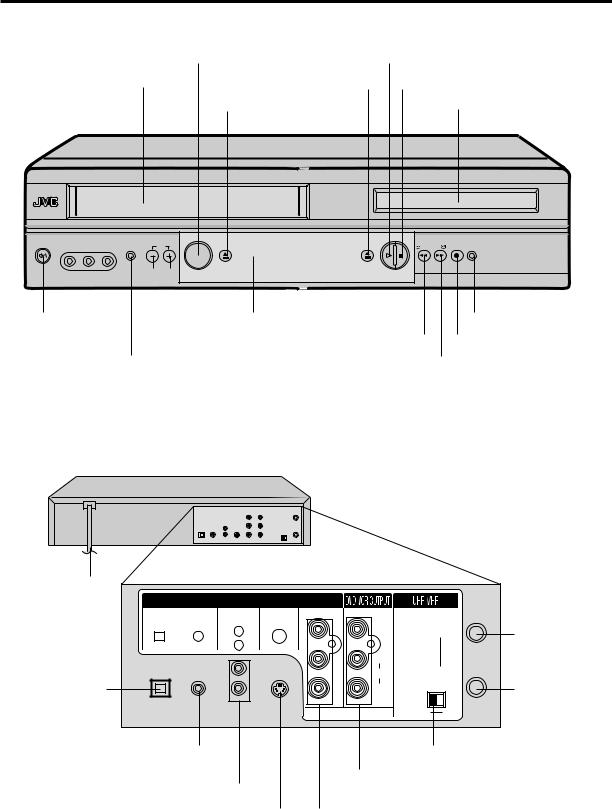
Parts and functions
Front |
|
|
|
|
|
|
|
VCR/DVD mode selector button |
|
|
PLAY button |
|
|
||
Cassette Loading Slot |
|
|
OPEN/CLOSE button |
STOP button |
|
||
|
|
|
EJECT button |
|
Disc tray |
||
|
|
|
|
|
PLAY STOP |
|
|
POWER |
VCR |
CH |
EJECT |
OPEN/CLOSE |
REW FF |
REC |
DVD |
VIDEO (M) L - AUDIO - R |
|||||||
|
|
VCR/DVD |
|
|
|
|
|
|
|
|
|
|
|
|
|
|
|
|
|
|
|
|
|
|
|
|
|
|
|
|
|
|
Remote sensor |
|
|
|
|
POWER |
|
|
|
|
|
|
DVD indicator |
|||||||
button |
|
|
|
|
|
|
|
|
REC button |
|||||
|
|
CHANNEL +/– buttons |
REW (Rewind) button |
|||||||||||
|
|
|
|
|
|
|
||||||||
|
AUDIO (L/R)/ |
|
VCR indicator |
|
FF (Fast Forward) button |
|||||||||
VIDEO IN jacks |
|
|
||||||||||||
|
|
|
|
|
|
|
|
|
|
|||||
Rear
AC power cord |
|
|
|
|
|
|
|
|
|
|
DVD OUTPUT |
|
|
|
|
|
|
DIGITAL AUDIO |
AUDIO |
S-VIDEO |
COMPONENT |
|
|
IN |
|
|
OPTICAL |
COAXIAL |
L |
|
Y |
VIDEO |
|
RF IN jack |
|
|
|
|
|
(ANT.) |
||||
|
|
R |
|
|
|
|
||
|
|
|
|
|
|
|
|
|
|
|
|
|
PB/CB |
L |
|
|
|
|
|
|
|
|
AUDIO |
|
OUT |
|
DVD OPTICAL |
|
|
|
PR/CR |
R |
|
( TV) |
RF OUT jack |
|
|
|
CH. |
|
||||
DIGITAL AUDIO |
|
|
|
|
|
|
|
|
|
|
|
|
|
3 |
|
4 |
|
OUT jack |
|
|
|
|
|
|
||
|
|
|
|
|
|
|
|
|
DVD COAXIAL DIGITAL |
3/4 Channel Selector Switch |
AUDIO OUT jack |
DVD/VCR common AUDIO (L/R)/VIDEO OUT |
|
|
DVD AUDIO (L/R) OUT jacks |
jacks |
DVD S-VIDEO OUT jack |
DVD COMPONENT OUT jacks |
8
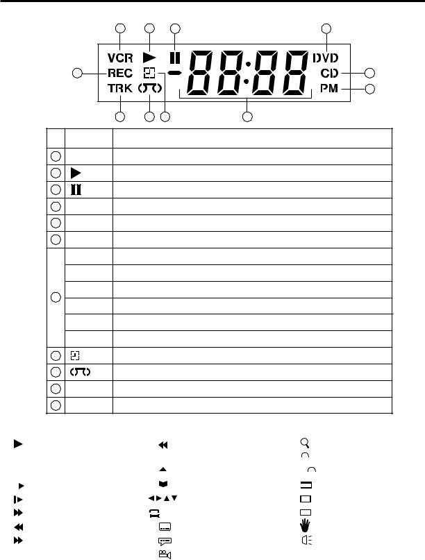
Display
Display window
1 |
2 |
3 |
4 |
|
11 |
|
|
|
5 |
|
|
|
|
|
6 |
|
|
10 |
9 |
8 |
7 |
No. |
Display |
|
|
|
Description |
1 |
VCR |
VCR mode |
|
|
|
2 |
|
Playback (lights) / Auto resume (flashes) |
|||
3 |
|
Still picture |
|
|
|
4 |
DVD |
DVD disc is inserted. |
|
||
5 |
CD |
CD is inserted. |
|
||
6 |
PM |
Display for afternoon (lights out in the morning) |
|||
|
10 : 00 |
Clock display (colon[ : ] flashes) |
|||
|
01 : 00 |
Counter display by hour/minute at VCR/DVD / by minute/second at CD |
|||
7 |
2 |
Track number display for CD |
|
||
CH02 |
TV channel display for VCR |
|
|||
|
|
||||
|
C036 |
CATV channel display |
|
||
|
L |
External input display |
|
||
8 |
|
Timer recording display |
|
||
9 |
|
Video tape is in the unit |
|
||
10 |
TRK |
Track display for CD |
|
||
11 |
REC |
Normal recording display (flashes during Instant Timer Recording - ITR) |
|||
Explanation for On-Screen-Symbol:
|
|
|
|
|
Playback |
|
|
|
|
|
|
|
|
|
Stop |
|
|
|
|
|
|
|
|
|
|
|
|
||
|
|
|
|
|
Still picture |
|
|
|
|
|
|
|
|
|
|
|
|||
|
|
|
|
|
Frame advanced playback |
|
|
|
|
|
|
|
|
|
|
|
|
|
|
|
|
|
|
|
Forward slowmotion |
|
|
|
|
|
|
|
|
|
Fast Forward playback |
A |
|
|
B |
|
|
|
|
|
|
|
|||
|
|
|
|
|
Review playback |
|
|
|
|
|
|
|
|
|
Skip chapter to forward |
|
|
|
|
|
|
|
|
|
|
|
|
|
|
|
|
|
|
|
direction |
|
|
|
|
Skip chapter to reverse |
|
|
|
Zoom |
direction |
|
|
|
Parental level locked |
|
|
|
||
|
|
|
||
Open or Close the tray |
|
|
|
Parental level unlocked |
|
|
|||
Auto resume |
|
|
|
Screen size: Normal TV |
Direction button’s mark |
|
|
|
Screen size: PAN SCAN |
A-B repeat |
|
|
|
Screen size: WIDE |
Subtitle language |
|
|
|
Shows Prohibited act |
Soundtrack language |
|
|
|
Output sound for Video-CD |
|
|
|
||
|
|
|
||
Angle |
|
|
|
|
Note:
Some discs may be displayed wrong or e.g. chapter number, playback time, etc. may not be displayed.
9
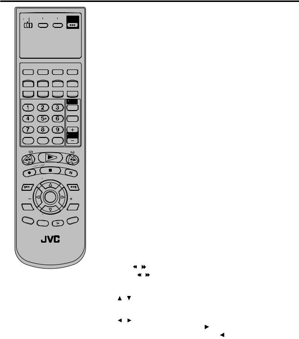
Remote control
TV |
VCR |
DVD |
POWER |
|
|
DVD MENU |
MARKER |
RETURN |
OPEN/ |
CLOSE |
|||
DISPLAY |
A.TRK |
C.RESET |
ZERO RETURN |
|
SUB TITLE |
ANGLE |
SEARCH |
|
MODE |
||
SP/EP |
|
|
|
PLAY |
ZOOM |
TITLE |
REPEAT |
MODE |
|
|
A-B |
|
|
|
|
|
|
|
TV |
|
|
|
|
|
|
|
POWER |
|
|
|
|
|
|
|
INPUT |
|
|
|
|
|
|
|
TV VOL |
0 |
TIMER |
|
TV/VCR |
|
|||
REW |
|
|
|
PLAY |
|
FF |
|
|
|
|
|
|
|
||
REC |
|
|
|
STOP |
|
PAUSE |
|
|
|
|
|
|
|
||
|
|
|
/VCR |
CH |
|
|
|
SKIP |
|
TV |
|
+ |
SKIP |
||
/INDEX |
|
|
|
|
|
|
/INDEX |
SET |
|
|
ENTER/ |
|
SET |
||
|
|
|
SELECT |
|
|
||
SET UP |
|
|
|
|
|
|
CANCEL |
MENU |
|
|
|
|
|
|
|
|
|
|
|
|
|
|
|
|
|
T |
|
|
|
— |
|
|
|
|
|
H |
|
||
|
|
|
V/VCR C |
|
|
||
OSD |
|
|
|
|
SLOW |
SKIP |
|
A. |
MONITOR |
|
|
SEARCH |
|||
|
|
|
|||||
|
|
|
|
|
|||
VCR/DVD/TV
JVC TV Remote Control
This Remote can control some functions (TV POWER, NUMBER(0-9), INPUT, TV VOL +/–, TV CH +/– and ENTER) of a remote controllable JVC TV by slide TV/VCR/DVD switch to TV.
(The POWER button on the upper right is not effective for the TV.)
NOTE:
•It’s not possible to operate a unit not equipped with a remote sensor.
•This Remote can control a JVC TV only.
•When you operate the VCR or DVD, the TV/VCR/DVD switch must be slided to VCR/DVD again. Otherwise the DVD/ VCR may not operate properly.
•Since this unit is combined type of DVD and VCR, the remote code of DVD is individual. So please note that the DVDkeys on the RCU of the other JVC RECEIVER/TV is not effective for this unit.
|
|
|
|
|
|
|
|
|
|
Page |
||
TV/VCR/DVD switch |
Switch to operate TV or VCR or DVD |
|
18,36 |
|||||||||
|
|
|
|
|
|
|
|
|
|
|
|
|
POWER |
Power on/off |
|
|
|
18 |
|||||||
|
|
|
|
|
|
|
|
|
|
|
|
|
DVD MENU |
Display menu of DVD software |
|
|
|
45 |
|||||||
|
|
|
|
|
|
|
|
|
|
|
|
|
MARKER |
Locating desired scene |
|
|
|
43 |
|||||||
|
|
|
|
|
|
|
|
|
|
|
||
RETURN |
Remove DVD set up menu |
|
|
36,47 |
||||||||
|
|
|
|
|
|
|
|
|
|
|
|
|
OPEN/CLOSE |
Open or Close the tray |
|
|
|
37 |
|||||||
|
|
|
|
|
|
|
|
|
|
|
|
|
DISPLAY |
Change the front Display mode |
|
|
|
27 |
|||||||
|
|
|
|
|
|
|
|
|
|
|
|
|
A.TRK |
|
|
|
Digital AUTO TRACKING |
|
|
|
26 |
||||
SUB TITLE |
Set Subtitle of a DVD disc |
|
|
|
44 |
|||||||
|
|
|
|
|
|
|
|
|
|
|
|
|
C. RESET |
Reset the counter to 00:00 |
|
|
|
27 |
|||||||
ANGLE |
|
|
|
Change playback angle of a DVD disc |
|
45 |
||||||
|
|
|
|
|
|
|
|
|
||||
ZERO RETURN |
Stop the tape when the counter reaches 00:00 |
27 |
||||||||||
SEARCH MODE |
Index for DVD |
|
|
|
39 |
|||||||
|
|
|
|
|
|
|
|
|
|
|
|
|
SP/EP |
|
|
|
Sets the tape speed for recording |
|
|
28,30 |
|||||
PLAY MODE |
Select playback mode |
|
|
40,41 |
||||||||
|
|
|
|
|
|
|
|
|
|
|
|
|
ZOOM |
|
|
|
Zoom (DVD/VCD) |
|
|
|
39 |
||||
|
|
|
|
|
|
|
|
|
|
|
|
|
TITLE |
|
|
|
Select title of a DVD disc |
|
|
|
45 |
||||
|
|
|
|
|
|
|
|
|
||||
REPEAT A-B |
Repeat playback between A and B (DVD/CD) |
40 |
||||||||||
|
|
|
|
|
|
|
|
|
|
|
|
|
0-9 |
|
|
|
|
|
|
Direct channel selection of TV |
|
|
20,28 |
||
|
|
|
|
|
|
|
Input setting |
|
|
39,41 |
||
|
|
|
|
|
|
|
Enter a password |
|
|
46,47 |
||
|
|
|
|
|
|
|
|
|
||||
TIMER |
|
|
|
Set the unit to start recording at a preset time. 31,32 |
||||||||
|
|
|
|
|
|
|
|
|
|
|
||
TV/VCR |
Switches between TV and VCR |
|
|
18,29 |
||||||||
|
|
|
|
|
|
|
|
|
|
|
|
|
TV POWER |
Turn the connected TV on or off |
|
|
|
10 |
|||||||
|
|
|
|
|
|
|
|
|
|
|
||
INPUT |
|
|
|
Switch the connected TV to external mode |
|
10 |
||||||
|
|
|
|
|
|
|
|
|
|
|
||
TV VOL +/– |
Adjust the connected TV’s volume |
|
|
10 |
||||||||
|
|
|
|
|
|
|
|
|
|
|
||
REW |
|
|
|
Rewind/Review playback |
|
25,26,38 |
||||||
|
|
|
|
|
|
|
|
|
|
|
|
|
PLAY |
|
|
|
Playback |
|
|
25,37 |
|||||
|
|
|
|
|
|
|
|
|
||||
FF |
|
|
|
Fast Forward/Forward search playback 25,26,38 |
||||||||
|
|
|
|
|
|
|
|
|
|
|
||
REC |
|
|
|
Recording |
|
28,30,34 |
||||||
|
|
|
|
|
|
|
|
|
|
|
|
|
STOP |
|
|
|
Stop |
|
|
25,37 |
|||||
|
|
|
|
|
|
|
|
|
|
|||
PAUSE |
|
|
|
Still picture/Recording pause on/off |
26,29,34,38 |
|||||||
|
|
|
|
|
|
|
|
|
|
|
||
SKIP |
|
|
|
/ |
|
|
Skip chapter to forward or reverse direction |
|
38 |
|||
|
|
|
|
|||||||||
INDEX |
|
/ |
|
|
Search for the INDEX mark of a tape |
|
|
27 |
||||
|
|
|
|
|
||||||||
|
|
|
|
|||||||||
TV/VCR CH +/– |
Select channel of the connected TV or VCR |
|
|
|||||||||
|
|
|
|
|
|
|
|
|
10,28,30,34 |
|||
/ |
|
|
|
|
|
|
Cursor buttons |
|
|
|
|
|
SET –/+ |
|
|
|
Setting buttons |
|
|
31,32 |
|||||
|
|
|
|
|
|
|
Manual tracking buttons in playback mode |
|
26 |
|||
/ |
|
|
|
|
|
|
Cursor buttons - To move Up in the VCR menu |
|||||
|
|
|
|
|
|
|
you press the . To move Down in the VCR |
|
|
|||
|
|
|
|
|
|
|
menu you press the . |
|
|
|
|
|
ENTER |
|
|
|
Enter information in the menu |
|
|
|
|
|
|||
SELECT |
Select option in the menu |
|
|
|
|
|
||||||
SET UP MENU |
Display menu of setup |
18,19,36,48-52 |
||||||||||
|
|
|
|
|
|
|
|
|
|
|
|
|
CANCEL |
Delete Timer program |
|
|
|
32 |
|||||||
|
|
|
|
|
|
|
Cancel input data in the setting mode |
23,31,39,41 |
||||
|
|
|
|
|
|
|
||||||
OSD |
|
|
|
Display VCR or DVD operation status |
29,52 |
|||||||
|
|
|
|
|
|
|||||||
A.MONITOR |
Switches sound between mono and stereo |
|
|
33 |
||||||||
|
|
|
|
|
|
|
Change sound track language of DVD |
|
|
44 |
||
|
|
|
|
|
|
|
|
|
||||
SLOW |
|
|
|
Slowmotion playback |
|
|
26,38 |
|||||
|
|
|
|
|
||||||||
SKIP SEARCH |
Skip the unwanted short material of a tape |
|
26 |
|||||||||
10
Remote control
Inserting Batteries
1 Open the battery compartment cover in the direction of the arrow.
2 Install two "AA" batteries (supplied), |
3 Replace the compartment |
paying attention to the polarity |
cover. |
diagram in the battery compartment. |
|
Battery precautions
The precautions below should be followed when using batteries in this device:
1.Use only the size and type of batteries specified.
2.Be sure to follow the correct polarity when installing the batteries as indicated in the battery compartment. Reversed batteries may cause damage to the device. To avoid a potential short circuit, insert the “–” end first.
3.Do not mix different types of batteries together (e.g. Alkaline and Carbon-zinc) or old batteries with fresh ones.
4.If the device is not to be used for a long period of time, remove the batteries to prevent damage or injury from possible battery leakage.
5.Do not try to recharge batteries not intended to be recharged; they can overheat and rupture. (Follow battery manufacturer’s directions.)
Remote control basics
•Press POWER to turn the DVD/VCR on or off.
•Make sure TV/VCR/DVD switch is set to VCR/DVD.
•Tap VCR CH + or VCR CH –to move through the channels one channel at a time.
•The VCR CH +/–and SET +/–are also used to navigate on-screen menu system.
•You can directly access specific channels using Number keys pad.
•Each press of VCR or DVD, switches the screen between the VCR screen (VCR mode) and the DVD screen (DVD mode).
Operation |
|
|
• Aim the remote control at the remote sensor and press control buttons |
|
|
to operate. |
|
|
• Operate the remote control within 30° angle on either side of the remote |
Approx. 5 meters |
|
sensor, up to a distance of Approx. 5 meters. |
||
|
Change the custom code for remote control
If you operate this DVD/VCR with another JVC’s VCR simultaneously arranging them side by side, the both recorders will react to this remote control. In this case, you can change the remote control and DVD/VCR to other frequency (“  ”). Then you can operate only this DVD/VCR with this changed remote control.
When you purchased, the DVD/VCR and remote control have been set to the frequency-“ 
 ”.
”.
Example: Change frequency to 

Remote control: |
|
|
|
|
While holding VCR, |
|
|
|
|
press 2(code: b) of |
TV |
VCR |
DVD |
POWER |
|
||||
Number keys. (in |
|
|
|
|
case of code: A, press 1)
DVD MENU |
MARKER |
RETURN |
OPEN/ |
CLOSE |
|
SUB TITLE |
ANGLE |
SEARCH |
|
MODE |
||
SP/EP |
|
|
|
PLAY |
ZOOM |
TITLE |
REPEAT |
MODE |
A-B |
||
|
|
|
TV |
|
|
|
POWER |
|
|
|
INPUT |
|
|
|
TVVOL |
0 |
TIMER |
TV/VCR |
|
DVD/VCR: |
|
|
|
In the POWER off mode, |
|
|
|
press and hold PLAY for |
|
|
|
more than 5 seconds. “b” |
|
|
|
will appear on the display |
OPEN/CLOSE |
REW FF |
REC DVD |
|
|
PLAY STOP |
|
and then disappear after |
|
|
|
approx. 4 seconds. |
|
|
|
NOTES:
•If the remote control has been set to b, the DVD/VCR also must be set to b. Otherwise, the DVD/VCR can not be operated with this remote control.
•To reset to “A”, repeat above procedure. However press 1 instead of 2.
11
Basic connections
If you are using an antenna system, follow these instructions. If you are a cable (CATV) subscriber,skip ahead to page 14 for the proper connections.
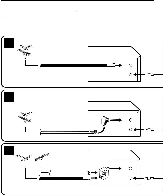
ANTENNA TO DVD/VCR CONNECTION
The DVD/VCR must be connected "between" the antenna and the TV. First, disconnect the antenna from the TV and connect it to the DVD/VCR.Then connect the DVD/VCR to the TV. Below are 3 common methods of connecting an antenna system to a DVD/VCR. Find the type of antenna system you are using and follow the connection diagram.
1 |
Combination VHF/UHF Antenna with 75 ohm Coaxial Cable |
DVD/VCR |
IN (ANT.)
75 ohm Coaxial Cable
OUT (TV)
2 |
Combination VHF/UHF Antenna with 300 ohm Twin Lead (Flat) Wire |
DVD/VCR |
Matching Transformer 300 ohm Input 75 ohm output (not supplied)
IN (ANT.)
OUT (TV)
300 ohm Twin Lead (Flat) Wire
3 |
Separate VHF and UHF Antennas |
DVD/VCR |
|
Combiner |
|
|
|
75/300 ohm Inputs |
|
UHF |
75 ohm output |
|
(not supplied) |
|
|
VHF |
|
|
|
300 ohm Twin Lead (Flat) Wire
IN (ANT.)
OUT (TV)
75 ohm Coaxial Cable
NOTE: If both VHF and UHF antennas have 300 ohm twin lead (flat) wires, use a combiner having two 300 ohm inputs and one 75 ohm output.
NOTES: •A clear picture will not be obtained by the DVD/VCR unless the antenna signal is good. Connect the antenna to the DVD/VCR properly.
•For better quality recording, an indoor antenna or a telescopic antenna is not recommended. The use of an outdoor type antenna is required.
•If you are not sure about the connection, please refer to qualified service personnel.
12
Basic connections
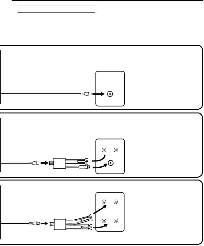
DVD/VCR TO TV CONNECTION
After you have connected the antenna to the DVD/VCR, you must connect the DVD/VCR to the TV.
Below are 3 common methods of connecting your DVD/VCR to a TV. Find the type of TV you are using and follow the connection diagram.
This DVD/VCR has a single 75 ohm output for connection to a TV. If your TV has separate VHF and UHF antenna inputs (numbers 2 and 3 below), use a splitter to connect the DVD/VCR to the TV for VHF and UHF reception.
75 ohm Coaxial Cable (supplied)
Splitter
75 ohm Input 75/300 ohm outputs
75 ohm Coaxial Cable (not supplied) (supplied)
Splitter
75 ohm Input
300 ohm outputs
75 ohm Coaxial Cable (not supplied) (supplied)
TV
VHF/UHF IN
TV
 UHF
UHF
 VHF
VHF
TV
 UHF
UHF
 VHF
VHF
NOTE: If a VHF or UHF antenna is used, set the TV/CATV menu option to the "TV" mode.
TV with single 75 ohm VHF/UHF antenna input
NOTE: If a VHF or UHF antenna is used, set the TV/CATV menu option to the "TV" mode.
TV with 300 ohm UHFand 75 ohm VHF antenna inputs
NOTE: If a VHF or UHF antenna is used, set the TV/CATV menu option to the "TV" mode.
TV with 300 ohm UHF and 300 ohm VHF antenna inputs
13
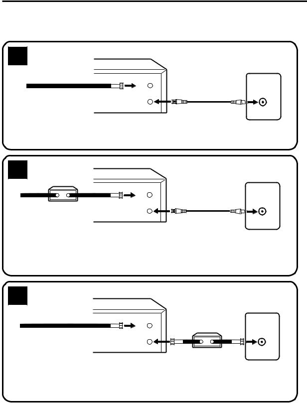
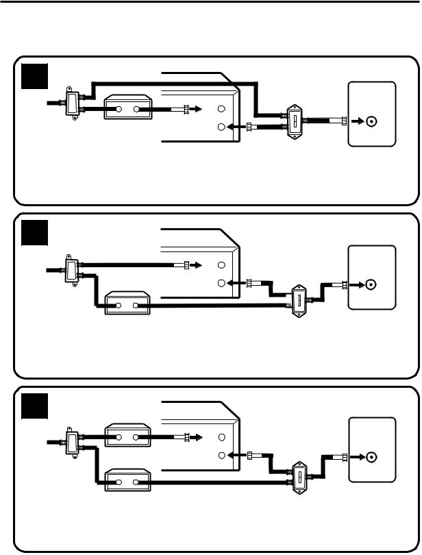
CATV (CABLE TV) connections
Many cable companies offer services permitting reception of extra channels including pay or subscription channels. This DVD/VCR has an extended tuning range and can be tuned to most cable channels without using a cable company supplied converter box, except for those channels which are intentionally scrambled. If you subscribe to a special channel which is scrambled, you must have a descrambler box for proper reception.
1 |
DVD/VCR |
|
|
|
IN |
|
(ANT.) |
|
Incoming Cable |
OUT (TV)
ALLOWS: * Recording of nonscrambled channels.
*Use of the programmable timer.
*Recording of one channel while watching another.
DVD/VCR
2 Converter/
Descrambler
IN (ANT.)
Incoming
Cable OUT
(TV)
TV
VHF/UHF IN (ANT)
TV
VHF/UHF IN (ANT)
ALLOWS: * Recording of channels through the converter box (scrambled and unscrambled).
*Using the programmable timer to record only the channel selected at the converter box.
PREVENTS: * Recording one channel while watching another. * Using the DVD/VCR tuner to select channels.
NOTE:
To record from converter/descrambler, DVD/VCR tuner must be tuned to the converter output channel, usually channel 3 or 4.
3 |
DVD/VCR |
|
|
|
TV |
|
IN |
Converter/Descrambler |
VHF/UHF |
|
Incoming Cable |
(ANT.) |
|||
|
|
|||
|
|
IN (ANT) |
||
|
OUT |
|
|
|
|
(TV) |
|
|
ALLOWS: * Recording of nonscrambled channels.
*Use of the programmable timer.
*Recording an unscrambled channel while watching any channel selected at the converter box.
PREVENTS: Recording scrambled channels.
NOTE:
If you are playing a tape or using the tuner built into the DVD/VCR, the converter must be set to the video channel output of the DVD/VCR (either 3 or 4).
NOTE: Whenever a Converter/Descrambler box is placed before the DVD/VCR, you must tune the DVD/VCR to the output of the Converter/Descrambler box, usually channel 3 or 4.
14
CATV (CABLE TV) connections
IMPORTANT: Make sure the TV/CATV menu option is set to the "CATV" mode.
This DVD/VCR cannot receive scrambled programs since it does not contain a descrambler. In order to receive scrambled programs, your existing descrambler must be used. Descrambler boxes are available from cable companies. Consult your local cable company for more information concerning connection to their descrambler equipment. There are many ways to connect your DVD/VCR to a cable system. Below are six common methods of connection.
4 |
|
DVD/VCR |
|
|
Splitter |
|
|
TV |
|
|
|
|
||
|
|
IN |
A/B Switch |
VHF/UHF |
Incoming |
|
IN (ANT) |
||
(ANT.) |
|
|||
A |
|
|||
|
Cable |
|
|
|
|
(TV) |
|
|
|
|
Converter/Descrambler |
B |
|
|
|
|
OUT |
|
|
ALLOWS: * Recording of one channel while watching another.
*Using the programmable timer to record only the channel selected at the converter box.
*Recording of all channels through the converter box.
PREVENTS: * Watching scrambled channels while recording another channel. * Using the DVD/VCR tuner to select channels.
5 |
DVD/VCR |
TV |
|
|
Splitter |
Incoming |
Converter/ |
Cable |
Descrambler |
IN |
VHF/UHF |
|
(ANT.) |
||
IN (ANT) |
||
|
||
OUT |
A/B Switch |
|
(TV) |
|

 A
A

 B
B
ALLOWS: * Recording of nonscrambled channels.
*Recording of one channel while watching another.
*Watching premium channels through the converter while recording nonscrambled channels.
*Using the programmable timer.
PREVENTS: Recording scrambled channels.
6 |
|
|
DVD/VCR |
|
Converter/ |
TV |
|
|
Splitter |
Descrambler |
|
|
|
|
Incoming |
Converter/ |
|
Cable |
||
Descrambler |
||
|
IN
(ANT.) VHF/UHF IN (ANT)
OUT |
A/B Switch |
(TV) |
|
|
A |
|
B |
ALLOWS: * Recording of all channels through the converter box.
*Recording a scrambled or unscrambled channel while watching another (scrambled or unscrambled) channel.
*Using the programmable timer to record only the channel selected at the converter box.
PREVENTS: Using the DVD/VCR tuner to select channels.
15

Playback Connection
The exact arrangement you use to interconnect various video and audio components to the DVD/VCR is dependent on the model and features of each component. Check the Owner's Manual provided with each component for the location of video and audio inputs and outputs.
Connect to a TV with Audio/Video Output
Use the supplied AUDIO/VIDEO Cord.
|
|
|
|
|
|
TV |
|
Audio (L) Output |
Video Output |
|
|||||
DVD/VCR |
|
|
|
|
|
|
|
|
DVD OUTPUT |
|
|
|
|
|
|
DIGITAL AUDIO |
AUDIO S-VIDEO COMPONENT |
|
|
|
IN |
|
|
OPTICAL COAXIAL |
Y |
|
VIDEO |
|
|
||
|
L |
|
|
(ANT.) |
|
||
|
R |
|
|
|
|
|
|
|
|
P /C |
|
L |
|
|
|
|
|
|
|
AUDIO |
|
OUT |
|
|
|
P /C |
|
R |
|
( TV) |
|
|
|
|
CH. |
|
|
||
|
|
|
|
|
|
|
|
|
|
|
|
|
3 |
4 |
|
Audio (R) Output |
|
|
|
|
To Video |
To Audio (R) Input |
|
|
|
|
|
Input |
|
||
|
|
|
|
|
|
To Audio (L) Input |
|
|
|
|
|
|
|
|
|
|
|
AUDIO/VIDEO Cord (supplied) |
|
||||
Connect to a TV with S-Video Output |
|
|
|
|
|
|
|
You can use the following connection only for DVD/CD playback. |
|
||||||
|
|
|
|
|
|
TV |
|
S-Video Cord (not supplied) |
|
||||||
DVD/VCR |
|
|
|
|
|
|
|
DVD OUTPUT |
|
|
|
|
|
|
|
DIGITAL AUDIO AUDIO |
S-VIDEO COMPONENT |
|
|
|
|
|
|
OPTICAL COAXIAL |
Y |
VIDEO |
|
IN |
|
|
|
L |
|
(ANT.) |
|
|
|
||
R |
|
|
|
|
|
|
|
|
P /C |
L |
|
|
|
|
|
|
|
AUDIO |
|
OUT |
|
|
|
|
P /C |
R |
|
(TV) |
|
|
|
|
CH. |
|
|
|
|
||
|
|
|
|
|
|
|
|
|
|
|
3 |
|
4 |
|
|
Audio (L) Output |
|
|
|
|
|
To S-Video Input |
To Audio (R) Input |
Audio (R) Output |
|
S-Video Output |
To Audio (L) Input |
||||
|
|
|
|
|
|
|
|
AUDIO Cord (not supplied)
Connect to a BS TUNER
Satellite
Antenna
 VHF/UHF
Antenna
TV
75 ohm Coaxial Cable (not supplied)
ANT. Input |
DVD/VCR |
To ANT. Input |
|
||||
|
|
|
|
|
|
||
|
|
|
|
|
|
|
|
BS Tuner |
|
|
|
|
|
|
|
|
|
DVD OUTPUT |
|
|
|
|
|
|
|
DIGITAL AUDIO AUDIO S-VIDEO |
COMPONENT |
|
|
IN |
|
|
|
OPTICAL COAXIAL |
Y |
VIDEO |
|
|
|
|
|
L |
|
(ANT.) |
|
||
|
|
R |
|
|
|
|
|
|
|
|
PB/CB |
L |
|
|
|
|
|
|
|
AUDIO |
|
OUT |
ANT. |
|
|
|
PR/CR |
R |
3 |
( TV) |
|
|
|
|
4 |
||||
|
|
|
|
|
CH. |
|
|
|
Video Output |
|
|
|
|
Output |
|
ANT. output |
|
|
|
|
|
||
|
|
|
|
|
|
75 ohm Coaxial |
|
|
Audio (L) Output |
|
|
|
|
||
|
|
|
|
|
Cable (supplied) |
||
|
Audio (R) Output |
|
|
|
|
To ANT. |
|
|
|
|
|
|
Input |
||
|
|
|
|
|
|
|
|
|
|
|
AUDIO/VIDEO Cord (supplied) |
||||
16
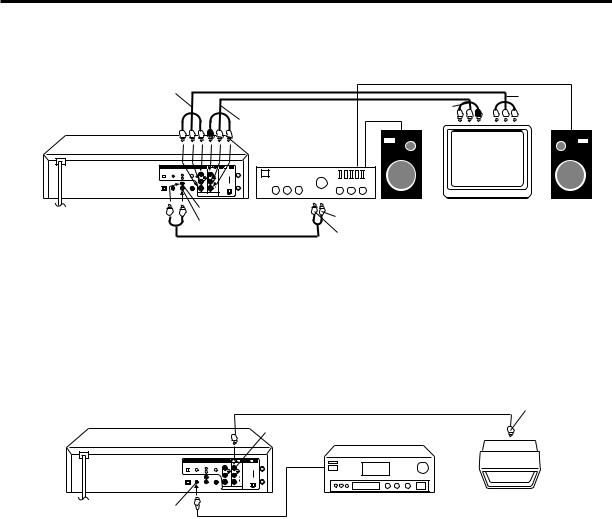
Playback Connection
Connect to a Stereo Amplifier with Audio Output
If your TV has a COMPONENT VIDEO IN jack, you can connect the DVD/VCR to the TV with a COMPONENT cable (not supplied) as shown below. COMPONENT VIDEO output jack can send higher-quality video signal to a TV than S-Video output.
COMPONENT VIDEO Cord (not supplied)
To Component |
|
|
|
|
|
|
Video Output |
|
|
|
AUDIO/VIDEO Cord (supplied) |
To Audio/Video Input |
|
DVD/VCR |
|
|
|
To Audio/Video Output |
|
|
|
|
|
|
Stereo Amplifier |
|
|
DVD OUTPUT |
|
|
|
|
|
|
DIGITAL AUDIO AUDIO |
S-VIDEO COMPONENT |
|
|
IN |
|
|
OPTICAL COAXIAL |
Y |
VIDEO |
|
|
|
|
L |
|
(ANT.) |
|
|
||
R |
|
|
|
|
|
|
|
P /C |
L |
|
|
|
|
|
|
AUDIO |
|
OUT |
|
|
|
P /C |
R |
|
( TV) |
|
|
|
CH. |
|
|
|
||
|
|
|
|
|
|
|
|
|
|
3 |
4 |
|
|
|
Audio (L) Output |
To Audio (L) Input |
||||
|
Audio (R) Output |
|||||
|
|
|
||||
To Audio (R) Input
AUDIO Cord (not supplied)
Connect to an AV Amplifier with built-in digital surround
To
Component


 Video Input
TV
If you are using an Amplifier with a built-in digital surround as follows, you can enjoy the various audio systems such as Dolby Digital and DTS by using the Optical or Coaxial Digital Output.
Use this connection to connect an:
•AV amplifier with built-in *Dolby Digital decoder
•AV amplifier with built-in *DTS decoder
|
Video cord (not supplied) |
To Video |
|
DVD/VCR |
|
||
Video Output |
Input |
||
|
|||
|
|
|
|
DVD OUTPUT |
|
|
|
|
|
DIGITAL AUDIO |
AUDIO |
S-VIDEO |
COMPONENT |
|
|
IN |
|
OPTICAL |
COAXIAL |
L |
|
Y |
VIDEO |
|
|
|
|
|
|
(ANT.) |
|||
|
|
R |
|
|
|
|
|
|
|
|
|
P /C |
L |
|
|
|
|
|
|
|
AUDIO |
|
OUT |
|
|
|
|
P /C |
R |
|
( TV) |
|
|
|
|
CH. |
|
||
|
|
|
|
|
|
3 |
4 |
Coaxial digital
Audio Output Coaxial digital cable (not supplied)
AV Amplifier with built-in various decoder as above
TV
NOTE:
You may connect to a TV with a Component video cable(not supplied) or S-Video cable(not supplied) instead of a video cable(not supplied).
Connecting the optical digital cable
You may connect to an AV Amplifier with an Optical digital cable (not supplied) instead of a Coaxial digital cable.
When you connect the optical digital cable (not supplied), remove the dust protection cap from the rear panel. When not using the optical digital cable, attach the dust protection cap to protect against dust.
NOTES:
•The OPTICAL, COAXIAL, AUDIO L/R, S-VIDEO and COMPONENT jacks are useful only for DVD section. The VHS signal is output only from the composite jack(DVD/VCR VIDEO OUTPUT) and UHF/VHF OUT.
•When you make the connections above, do not set DOLBY DIGITAL to DOLBY DIGITAL or DTS to ON on the AV Amplifier. If you do, a loud noise will suddenly come out from the speakers, affecting your ears or causing the speakers to be damaged.
•Caution for the optical digital audio output connector: Do not connect to an amplifier (with an optical digital input connector) which does not contain a Dolby Digital or DTS decoder. Otherwise, any attempt to play DVDs may cause such a high level of noise that it may be harmful to your ears and damage your speakers.
•DTS audio will be output only from the COAXIAL or OPTICAL output. To hear DTS audio, DTS-Decoder is necessary.
•When playing DTS-encoded CDs, only noise will be heard from the speakers or analogue stereo outputs.
•Some DTS decoders which do not support DVD-DTS interface may not work properly with the unit.
17
Setting the Video Channel / Setting the language
Setting the Video Channel
To view playback of a recorded tape, or to watch a program selected by the VCR's channel selector, the TV must be set to channel 3 or 4 (video channel).
TV |
VCR |
DVD |
POWER |
|
|
DVD MENU |
MARKER |
RETURN |
OPEN/ |
CLOSE |
|||
DISPLAY |
A.TRK |
C.RESET |
ZERO RETURN |
|
SUB TITLE |
ANGLE |
SEARCH |
|
MODE |
||
SP/EP |
|
|
|
PLAY |
ZOOM |
TITLE |
REPEAT |
MODE |
A-B |
|
|
|
|
|
|
|
TV |
|
|
|
|
|
|
|
POWER |
|
|
|
|
|
|
|
INPUT |
|
|
|
|
|
|
|
TV VOL |
0 |
TIMER |
|
TV/VCR |
|
|||
REW |
|
|
|
PLAY |
|
FF |
|
|
|
|
|
|
|
||
REC |
|
|
|
STOP |
|
PAUSE |
|
|
|
|
|
|
|
||
|
|
|
/VCR |
CH |
|
|
|
SKIP |
|
TV |
|
+ |
SKIP |
||
/INDEX |
|
|
|
|
|
|
/INDEX |
SET |
|
|
ENTER/ |
|
SET |
||
|
|
|
SELECT |
|
|
||
SET UP |
|
|
|
|
|
|
CANCEL |
MENU |
|
|
|
|
|
|
|
|
|
|
|
|
|
|
|
|
|
T |
|
|
|
— |
|
|
|
|
|
H |
|
||
|
|
|
V/VCR C |
|
|
||
OSD |
|
|
|
|
SLOW |
SKIP |
|
A. |
MONITOR |
|
|
SEARCH |
|||
|
|
|
|||||
|
|
|
|
|
|||
NOTES:
•If the unit does not operate properly, or No key operation (by the unit and/ or the remote control): Static electricity, etc., may affect the player's operation. Disconnect the AC power cord once, then connect it again.
•If no buttons are pressed for more than 60 seconds,the MENU screen will return to normal TV operation automatically.
•Both the VCR and the DVD have their own menu options (See page 36).
When a TV is connected with the 75 ohm coaxial cable only.
1 Press POWER to turn on the DVD/VCR.
2 Slide TV/VCR/DVD switch to VCR/DVD. Then press VCR to select the VCR mode. The VCR indicator on the front panel will light.
3 Set the 3/4 Channel selector switch on the rear panel to CH 3 or 4.
4 Turn ON the TV and set to CH 3 or 4 to correspond with the channel selected in step 3.
5 Press TV/VCR to select the VCR position. The VCR indicator will appear in the display.
6 Select any channel to receive a TV station in your area. The channel number will appear on the screen for about 4 seconds.
For a push-button TV tuner
If CH 3 or 4 corresponding to the video channel cannot be tuned on your TV, proceed as follows: set the VCR 3/4 channel selector and the TV to CH 3 or 4, play back a prerecorded tape and tune the TV to receive a sharp color picture from the video cassette recorder. Refer to your TV owner's manual for details.
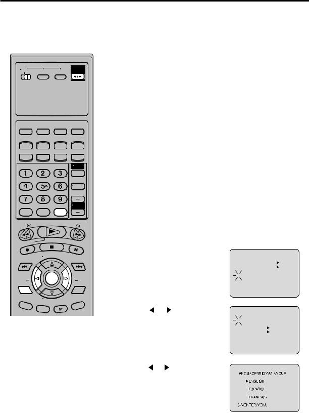
Setting the language
You can choose from three different languages (English, French and Spanish) for the on-screen displays.
1 Press SETUP MENU,
If you use the unit for the first time and press SETUP MENU, instead of the main menu screen on the right the SYSTEM SET UP menu screen in step 2 may appear.
2 Press or to select the “LANGUAGE” option, then press
ENTER.
|
MENU |
|
|
|
TIMER REC SET |
ON |
OFF |
|
|||
|
|||
|
AUTO REPEAT |
||
|
|||
|
SAP |
ON |
OFF |
|
|||
|
CH SET UP |
|
|
|
SYSTEM SET UP |
|
|
|
|
|
|
·+/-/ENTER/MENUÒ |
|
|
|
SYSTEM SET UP
 CLOCK SET
 LANGUAGE/IDIOMA/LANGUE
  NO NOISE BACKGROUND
|
ON |
OFF |
|
AUTO CLOCK ON |
OFF |
|
STANDARD TIME |
|
|
|
 DAYLIGHT SAVING TIME
á+/-/ENTER/MENUñ
3 Press or to select the desired language: English (ENGLISH), Spanish (ESPAÑOL) or French (FRANCAIS), then press ENTER.
4 Press SETUP MENU until the MENU screen is cleared.
18
 Loading...