


HD-61FC97
Table of contents
 Loading...
Important Note:
In the spaces below, enter the model and serial number of your television (located
at the rear of the television cabinet). Staple your sales receipt or invoice to the
inside cover of this guide. Keep this user’s guide in a convenient place for future
reference. Keep the carton and original packaging for future use.
LCT2067-001A-A
0606TNH-II-IM
Model Number:
Serial Number:
Illustration of HD-70FH97 and RM-C14G
For Models:
HD-56FH97
HD-61FH97
HD-70FH97
HD-56FN97
HD-61FN97
HD-70FN97
HD-56FC97
HD-61FC97
Projection Television Users Guide
2
Important Safety Precautions
WARNING: TO PREVENT FIRE OR SHOCK HAZARDS, DO NOT EXPOSE THIS
APPARATUS TO RAIN OR MOISTURE.
CAUTION: TO INSURE PERSONAL SAFETY, OBSERVE THE FOLLOWING RULES
REGARDING THE USE OF THIS UNIT.
1. Operate only from the power source specified on the unit.
2. Avoid damaging the AC plug and power cord.
3. Avoid Improper installation and never position the unit where good ventilation is unattainable.
4. Do not allow objects or liquid into the cabinet openings.
5. In the event of trouble, unplug the unit and call a service technician. Do not attempt to repair
it yourself or remove the rear cover.
Changes or modifications not approved by JVC could void the warranty.
* When you don’t use this TV set for a long period of time, be sure to disconnect both the
power plug from the AC outlet and antenna for your safety.
* To prevent electric shock do not use this polarized plug with an extension cord, receptacle or
other outlet unless the blades can be fully inserted to prevent blade exposure.
CAUTION: To reduce the risk of electric shock. Do not
remove cover (or back). No user serviceable
parts inside. Refer servicing to qualified service
personnel.
The lightning flash with arrowhead symbol, within an
equilateral triangle is intended to alert the user to the
presence of uninsulated “dangerous voltage” within the
product’s enclosure that may be of sufficient magnitude
to constitute a risk of electric shock to persons.
The exclamation point within an equilateral triangle is
intended to alert the user to the presence of important
operating and maintenance (servicing) instructions in
the literature accompanying the appliance.
RISK OF ELECTRIC SHOCK
DO NOT OPEN
CAUTION
NOTICE (for USA)
This product has a High Intensity Discharge (HID) lamp that
contains a small amount of mercury. It also contains lead in some
components. Disposal of these materials may be regulated in your
community due to environmental considerations. For disposal or
recycling information, please contact your local authorities, or the
Electronics Industries Alliance: http://www.eiae.org

3
1) Read these instructions.
2) Keep these instructions.
3) Heed all warnings.
4) Follow all instructions.
5) Do not use this apparatus near water.
6) Clean only with dry cloth.
7) Do not block any ventilation openings. Install in accordance with the manufacturer's instructions.
8) Do not install near any heat sources such as radiators, heat registers, stoves, or other apparatus
(including amplifiers) that produce heat.
9) Do not defeat the safety purpose of the polarized or grounding-type plug. A polarized plug has
two blades with one wider than the other. A grounding type plug has two blades and a third
grounding prong. The wide blade or the third prong are provided for your safety. If the provided
plug does not fit into your outlet, consult an electrician for replacement of the obsolete outlet.
10) Protect the power cord from being walked on or pinched particularly at plugs, convenience
receptacles, and the point where they exit from the apparatus.
11) Only use attachments/accessories specified by the manufacturer.
12) Use only with a cart, stand, tripod, bracket, or table specified by the manufacturer, or sold with
the apparatus. When a cart is used, use caution when moving the cart/apparatus combination to
avoid injury from tip-over.
IMPORTANT SAFETY INSTRUCTIONS
This product incorporates copyright protection technology that is protected by U.S. patents
and other intellectual property rights. Use of this copyright protection technology must
be authorized by Macrovision, and is intended for home and other limited viewing uses
only unless otherwise authorized by Macrovision. Reverse engineering or disassembly is
prohibited.
Some pay-per-view programs may be licensed from producers as "view-only" programs.
These are copyrighted programs and may not be copied or reproduced for any purpose
without the express written permission of the copyright owner.
For best viewing, if your VCR is "ON", turn the TV/VCR switch to the "TV" position.
4
13) Unplug this apparatus during lightning storms or when unused for long periods of time.
14) Refer all servicing to qualified service personnel. Servicing is required when the apparatus has
been damaged in any way, such as power-supply cord or plug is damaged, liquid has been
spilled or objects have fallen into the apparatus, the apparatus has been exposed to rain or
moisture, does not operate normally, or has been dropped.
15) Apparatus shall not be exposed to dripping or splashing and no objects filled with liquids, such as
vases, shall be placed on the apparatus.
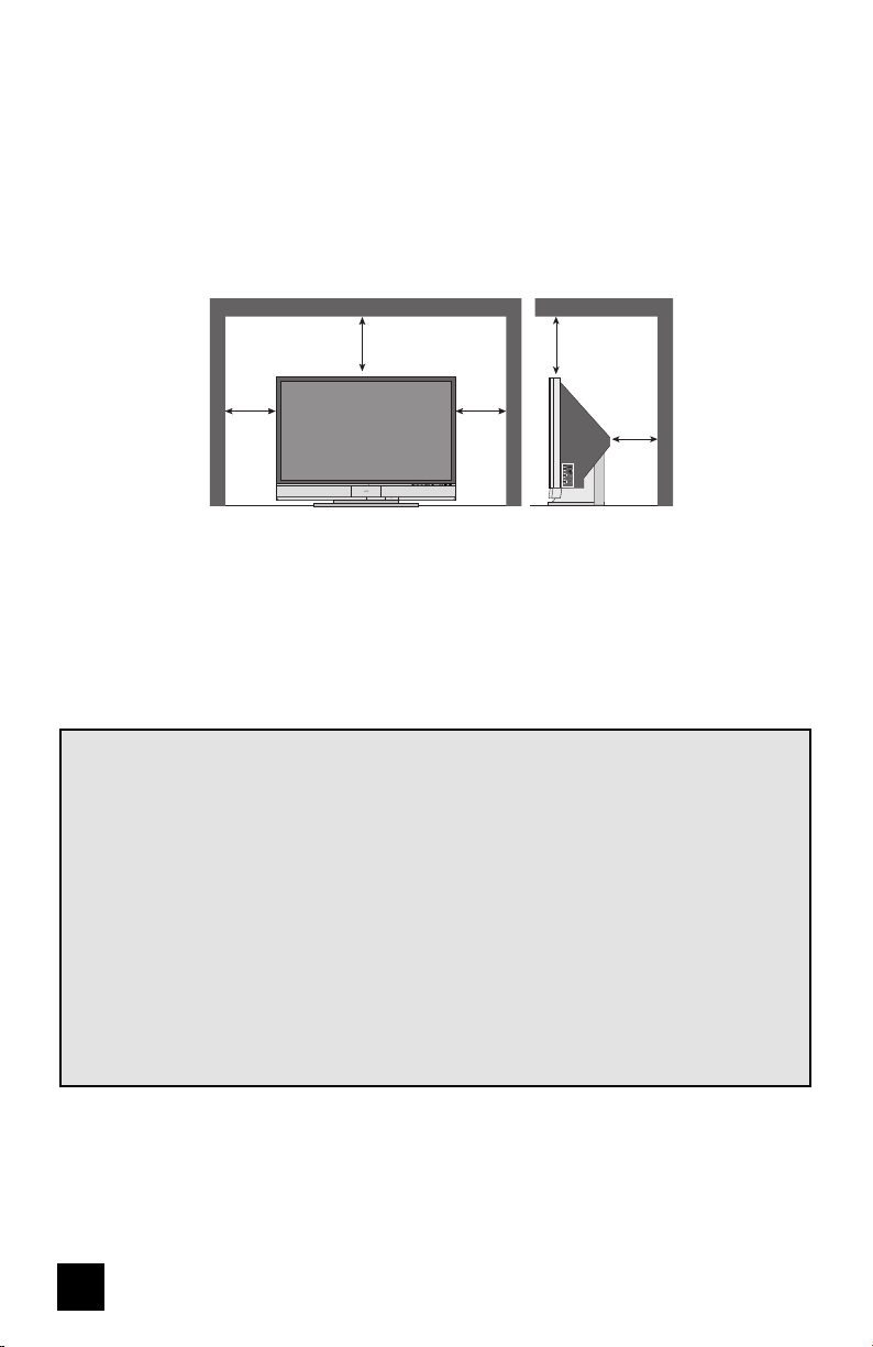
16) Avoid improper installation and never position the unit where good ventilation is impossible. When
installing this TV, distance recommendations must be maintained between the set and the wall,
as well as inside a tightly enclosed area or piece of furniture. Keep to the minimum distance
guidelines shown for safe operation.
17) Cautions for installation
— Do not tilt the TV towards the left or right, or towards the back.
— Install the TV in a corner on the floor so as to keep cords out of the way.
— The TV will generate a slight amount of heat during operation. Ensure that sufficient space is
available around the TV to allow satisfactory cooling.
18) Make enough room for inserting and removing the power plug. Place the TV as close to the
outlet as possible. The main power supply for this TV is controlled by inserting or removing the
power plug.
150 mm
200 mm
150 mm
200 mm
50 mm
VOLUME
INPUT-4
CHANNEL
OPERATE
+
–
+
–
MENU
S-VIDEO
VIDEO
L/MONO
R
AUDIO
OVER
INPUT
LAMP/PROGRAMPOWER
FCC Notice:
Note: This equipment has been tested and found to comply with the limits for a Class B
digital device, pursuant to Part 15 of the FCC Rules. These limits are designed to provide
reasonable protection against harmful interference in a residential installation. This
equipment generates, uses and can radiate radio frequency energy and, if not installed
and used in accordance with the instructions, may cause harmful interference to radio
communications. However, there is no guarantee that interference will not occur in a
particular installation. If this equipment does cause harmful interference to radio or television
reception, which can be determined by turning the equipment off and on, the user is
encouraged to try to correct the interference by one or more of the following measures:
– Reorient or relocate the receiving antenna.
– Increase the separation between the equipment and receiver.
– Connect the equipment into an outlet on a circuit different from that to which the receiver is
connected.
– Consult the dealer or an experienced radio/TV technician for help.
• FCC notice is only for HD-56FH97, HD-61FH97, HD-70FH97, HD-56FN97, HD-61FN97 and
HD-70FN97.

5
Warnings
Caring for the Cabinet
Caring for the Screen
Normally, light dusting with a soft, non-scratching duster will keep your TV clean.
If you wish to wipe down the television, first unplug it. Then wipe gently with a soft cloth, slightly
moistened with water. You can add a few drops of mild liquid detergent to the water to help
remove spots of oily dirt.
• DO NOT allow liquid to enter the TV through the ventilation slots.
• DO NOT use strong or abrasive cleaners on the TV.
• DO NOT spray liquids or cleaners directly on the TV’s surface.
• DO NOT rub or scrub the TV harshly. Wipe the set gently with a soft cloth.
The screen is treated with an electrostatic-proof coating. When it gets dirty, wipe it gently with a
soft cloth. If the screen is very dirty, wipe it down with a cloth dipped in a diluted kitchen cleaner
and thoroughly wrung-out. Then wipe immediately after with a clean, dry cloth.
Do not apply alcohol, organic solvents (like acetone), acidic or alkaline cleansers to the screen.
These will remove the coating layer and cause discolorations.
Do not push or hit the screen. This could cause scratches on the screen surface and image
distortions.

6
Thank you for purchasing a JVC HDTV-ready projection television which uses the high-quality
HD-ILA projection system. This is one of the highest quality and most technologically advanced
televisions available today. It is recommended that you read this instruction manual before using
your television in order to learn about it’s many features. Cautions related to the safe use of the
device and important information which will help you to be able to use this device for a long time
is in the Appendix. Once again, thank you for purchasing this television and please enjoy using
it.
This television uses a lamp to project the picture onto the screen. Before using this television,
please read the safety cautions and information about this television which are summarized
below.
1. When the power is turned on, the warming up commences
This television uses a lamp to project the picture onto the screen. Once the lamp has warmed
up, you can enjoy the pictures at their full brightness. What happens when the power is turned
on is explained below. Immediately after the power is turned on, since the lamp has not had
time to warm up, the picture is displayed only dimly on the screen. As the lamp warms up, the
picture becomes brighter. It takes approximately one minute for the lamp to warm up to it’s
normal operating temperature. There are 2 LED indicators on the front panel of the television
that can be used as a guide. When the POWER button is pressed, the LAMP/PROGRAM LED
indicator blinks in orange for approximately 1 minute at approximately every 2 seconds, and then
goes out.
Note: It is impossible to turn the power off during this period. After 1 or more minutes have
passed, you can turn off the power.
2. Cooling the inside of the television and the lamp
Cooling is also performed while the television is being shut down.
When the POWER button is pressed to turn off the power, the following operations are
performed. When the television is turned off, the picture on the screen disappears. Once
the screen is dark, cooling is performed for approximately 1 minute. When the cooling is
being performed, the LAMP/PROGRAM LED indicator on the front panel blinks in orange at
approximately every 3 seconds. The television can not be operated while the cooling is
being performed. After the cooling has been performed for 1 minute, the power is turned
off. Do not remove the electrical plug until after the cooling process has completed. If
the electrical plug is removed before the cooling process has completed, the internal circuits
and lamp may overheat leading to the life of the lamp being shortened and the possibility of
malfunctions.
Do not block the ventilation holes.
Do not block the ventilation holes while the power is turned on. Do not block the air intake holes
behind the speaker grills.
3. The lamp is a consumable item
Replace the lamp when it has blown or when the picture becomes dark. The lamp is a user
replaceable item. The lamp must be recycled. For a detailed explanation on how to recycle the
lamp, refer to the Appendix and the instructions that are included with the replacement lamp kit.
The life of the lamp changes depending on the atmospheric temperature and altitude in which
the TV is being used.
Warnings
In order to use the television for a long time

7
4. The television requires a lot of electrical power
It is recommended that the television is connected directly to the wall socket, and not to another
device. When connecting the television to a wall socket that is being used by another device, or
when using an extension cord, be careful not to exceed the electrical capacity of the socket.
Do not turn the power on and off repeatedly in a short amount of time.
It subjects the television and the lamp to stress and may lead to malfunctions and the life of the
lamp being shortened.
5. The screen is made of plastic
Handle the screen very carefully as it can scratch easily. Do not rub, hit or press on it with any
hard objects. When the screen is dirty, gently wipe it with a soft cloth. Refer to the Appendix for
details on how to clean the screen.
6. Caution! Warm air from the air ducts
This unit has an air duct for cooling. The duct will blow warm air while the television is operating.
When placing the television, make sure not to locate it too close to wallpaper. The warm air
could cause the color of the wallpaper to change. Also, take care to keep children and pets
away from the warm air ducts. Long exposure to the warm air from the ducts could cause a
minor burn.
7. Caution! Moving this television
When lifting this television, Do not hold by the screen frame. Holding the screen frame could
cause it to detach, causing the television to fall.
8. Do not replace the lamp immediately after use
The lamp becomes extremely hot during use. If the lamp is touched immediately after use
before it has a chance to cool down, there is a danger of burns. Be careful when handling the
lamp.
9. Do not touch the lamp glass
If the lamp is used when there is dirt from fi ngers on the lamp glass, there is a possibility of the
lamp breaking. Be careful not to touch the lamp glass.
10. ILA element characteristics
Do not project still pictures or pictures that have still segments for a long period of time. The still
parts of the picture may remain on the screen. This is a characteristic of ILA elements and not a
malfunction. The picture will disappear over time.
11. Condensation
When a heater is turned on or the television is moved from a cold place to a hot place, droplets
of water may form on the lamp and screen. This is called condensation. If the television is used
while this condensation is still present, the picture may seem distorted, and the inside of the
screen may become dirty. In this case, wait until the condensation has gone before using the
television.
12. Do not open the rear cabinet of this television
This television has a DIGITAL-IN terminal. Opening up the rear cabinet will violate the copyright
of the program or software shown on the television. Please do not open the rear cabinet.
13. Usable Time
Do not keep the TV on for more than 24 hours consecutively. There is a possibility of the life of
the lamp being shortened.
Warnings

8
Table of Contents
Important Safety Precautions . . 2
Warnings . . . . . . . . . . . . . . . 5
Quick Setup . . . . . . . . . . . . . . 9
Unpacking your TV . . . . . . . . . . . . 9
TV Models . . . . . . . . . . . . . . . . 10
TV Remote Control . . . . . . . . . . . 12
Getting Started . . . . . . . . . . . . . 13
The Remote Control . . . . . . . . . . 13
Connecting Your Devices . . . . . . . 14
Interactive Plug In Menu . . . . . . . . 27
Programming your remote . . . . . . . 30
Onscreen Menus . . . . . . . . . 34
Using the Guide . . . . . . . . . . . . . 34
Onscreen Menu System . . . . . . . . . 35
Initial Setup . . . . . . . . . . . . . 37
Auto Tuner Setup . . . . . . . . . . . . 37
Channel Summary . . . . . . . . . . . . 38
Channel Label . . . . . . . . . . . . . 39
V-Chip . . . . . . . . . . . . . . . . . . 40
Set Lock Code . . . . . . . . . . . . . 46
Language . . . . . . . . . . . . . . . . 47
Closed Caption . . . . . . . . . . . . . 47
Auto Shut Off . . . . . . . . . . . . . . 50
XDS ID . . . . . . . . . . . . . . . . . 50
Noise Muting . . . . . . . . . . . . . . 50
Front Panel Lock . . . . . . . . . . . . 51
V1 Smart Input . . . . . . . . . . . . 51
Video Input Label . . . . . . . . . . 52
Position Adjustment . . . . . . . . . . . 53
Power Indicator . . . . . . . . . . . . . 53
Video-1 Monitor Out . . . . . . . . . . 54
TV Speaker . . . . . . . . . . . . . . . 54
Audio Out . . . . . . . . . . . . . 54
Digital-In . . . . . . . . . . . . . . . 55
Digital-In1 Audio . . . . . . . . . . . 55
Center CH Input . . . . . . . . . . . . 56
Digital Setup . . . . . . . . . . . . . 56
Antenna Level . . . . . . . . . . . . 57
Digital Sound . . . . . . . . . . . . . . 57
Aspect Ratio . . . . . . . . . . . . . . 57
Cable Card Application . . . . . . . . . 58
i.LINK Auto Play . . . . . . . . . . . . 58
Software Update . . . . . . . . . . . . 58
Picture Adjust . . . . . . . . . . . . . 59
Picture Settings . . . . . . . . . . . . . 59
Color Temperature . . . . . . . . . . . . 59
Color Management . . . . . . . . . . . . 60
Dynamic Gamma . . . . . . . . . . . . . 60
Advanced Smart Picture . . . . . . . . 60
Digital VNR . . . . . . . . . . . . . . . . 61
MPEG NR . . . . . . . . . . . . . . . 61
Reset . . . . . . . . . . . . . . . . . . 61
Sound Adjust . . . . . . . . . . . . . 62
Sound Settings . . . . . . . . . . . . . 62
Turn On Volume . . . . . . . . . . . . . 62
Volume Limit . . . . . . . . . . . . . . 62
Reset . . . . . . . . . . . . . . . . . . 62
Clock/Timers . . . . . . . . . . . . . . . . 63
Set Clock . . . . . . . . . . . . . . . . 63
On/Off Timer . . . . . . . . . . . . . . . 64
Lamp Timer Reset . . . . . . . . . . . . . 65
Button Functions . . . . . . . . . . 66
Multi Screen Function . . . . . . . . . . 66
Twin . . . . . . . . . . . . . . . . . . 66
Index . . . . . . . . . . . . . . . . . 67
Freeze . . . . . . . . . . . . . . . . . . 67
Swap . . . . . . . . . . . . . . . . . 67
Select . . . . . . . . . . . . . . . . . . 67
Power . . . . . . . . . . . . . . . . . . 68
Number Buttons . . . . . . . . . . . . . 68
Tune . . . . . . . . . . . . . . . 68
Input . . . . . . . . . . . . . . . . . . . 68
Channel +/- . . . . . . . . . . . . . 69
Volume +/- . . . . . . . . . . . . . 69
TheaterPro D6500K . . . . . . . . . . . 69
Return+/TV . . . . . . . . . . . . . . . 69
Sound . . . . . . . . . . . . . . . . . . 70
Muting . . . . . . . . . . . . . . . . . . 70
Video Status . . . . . . . . . . . . . . . 71
Natural Cinema . . . . . . . . . . . . . 71
Sleep Timer . . . . . . . . . . . . . . . 72
ML/MTS . . . . . . . . . . . . . . . . . 72
Display . . . . . . . . . . . . . . . . . 73
C.C. . . . . . . . . . . . . . . . . . . . 73
Favorite . . . . . . . . . . . . . . . . 74
Aspect . . . . . . . . . . . . . . . . . 75
Aspect Ratios . . . . . . . . . . . . . 75
Menu . . . . . . . . . . . . . . . . . . 76
OK . . . . . . . . . . . . . . . . . . . 76
Back . . . . . . . . . . . . . . . . . . . 76
TV/CATV Slide Switch . . . . . . . . . . 77
VCR/DVD Slide Switch . . . . . . . . . 77
VCR Buttons . . . . . . . . . . . . . . . 77
DVD Buttons . . . . . . . . . . . . . . . 77
Light . . . . . . . . . . . . . . . . . . 77
D/A (Digital/Analog) . . . . . . . . . 78
Sub Channel . . . . . . . . . . . . . 78
Guide . . . . . . . . . . . . . . . 78
i.LINK Menu . . . . . . . . . . . . . . 79
Timer . . . . . . . . . . . . . . . . 81
OSD Information . . . . . . . . . . 83
Cable Card Information . . . . . 84
Lamp Replacement . . . . . . . 85
Troubleshooting . . . . . . . . . . 90
Specifications . . . . . . . . . . 92
Warranty . . . . . . . . . . . . . 94
Authorized Service Center . . . 95

9
AA
Batteries x 2
Television x 1
Remote Control x 1
Note: Your television
and/or remote
control may differ
from the examples
illustrated here.
Quick Setup
Thank you for your purchase of a JVC Color Television. Before you begin setting up your new
television, please check to make sure you have all of the following items. In addition to this
guide, your television box should include:
AA Alkaline
AA Alkaline
INPUT
INDEX
ASPECT
FREEZE
SWAP
SELECT
RETURN+
FAVORITE
THEATER
PRO
NATURAL
CINEMA
VIDEO
STATUS
TIMER
i.LINK MENU
SOUND
LIGHT
TV
CATV VCR DVD
MUTING
MENU
BACK
GUIDE
RM-C14G
REW
VCR CHANNEL
PREV NEXT
VCR DVD
POWER
TV VCR
FFPLAY
REC PAUSE
OPEN CLOSE
STILL PAUSE
STOP
CH
CH
VOL VOL
OK
MULTI SCREEN
TWIN
D/A
123
456
789
0
TUNE
TV
POWER
C.C.
SUB
CHANNEL
SUB
ML/MTS
SLEEP
DISPLAY
+
LAMP/PROGRAMPOWER
2-WAY SPLITTER
Two Way Splitter x 1
RF Cables x 2
Unpacking your TV
We recommend that before you start using your new television, you read your entire User’s
Guide so you can learn about your new television’s many great features. If you’re anxious to
start using your television right away, a quick setup guide follows on the next few pages.
10
75Ω
(VHF/UHF)
OVER
CENTER CHANNEL INPUT
LICENSED UNDER THE
FOLLOWING U.S. PATENTS
6,183,091
6,419,362
i.LINK IN/OUT
S400(TS)
ATS C
/DIGITAL CABLE IN
CABLE CARD
OPTICAL OUT
Digital Audio
SERVICE ONLY
PC IN
(D-SUB)
INPUT-1
INPUT-2
INPUT-3
HDMI 1
INPUT-1
INPUT-2
VIDEO
VIDEO
VIDEO
R - AUDIO - L
R - AUDIO - L
R - AUDIO - L
R - AUDIO - L
Y Pb Pr
Y Pb Pr
S-VIDEO
S-VIDEO
OVER
DIGITAL-IN
1
2
RS-232C
VIDEO R L
R L
S-VIDEO
MONITOR
/REC OUT
AUDIO
OUTPUT
INPUT-3
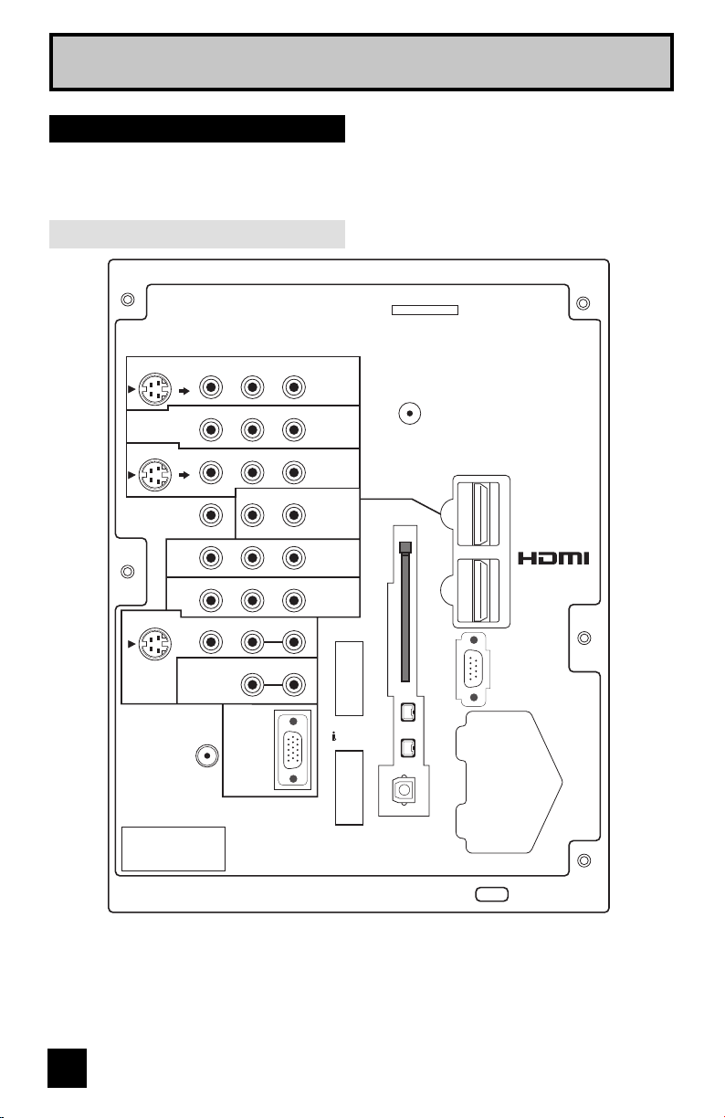
Quick Setup
Before you connect your television to another device, please refer to the proper diagrams for
your specific TV and remote. These will help assist you in understanding how to connect your
television to another device, as well as use the remote to set up your television.
Rear Panel Diagram
Notes:
• The terminal labeled "SERVICE ONLY", is exclusively used to update the software version.
• For governing the usage of the RS-232C terminal, consult your dealer. (HD-56FH97,
HD-61FH97 or HD-70FH97 ONLY)
• HD-56FC97 or HD-61FC97 does not have PC IN terminal and CENTER CHANNEL INPUT
terminal.
TV Models
11
Quick Setup
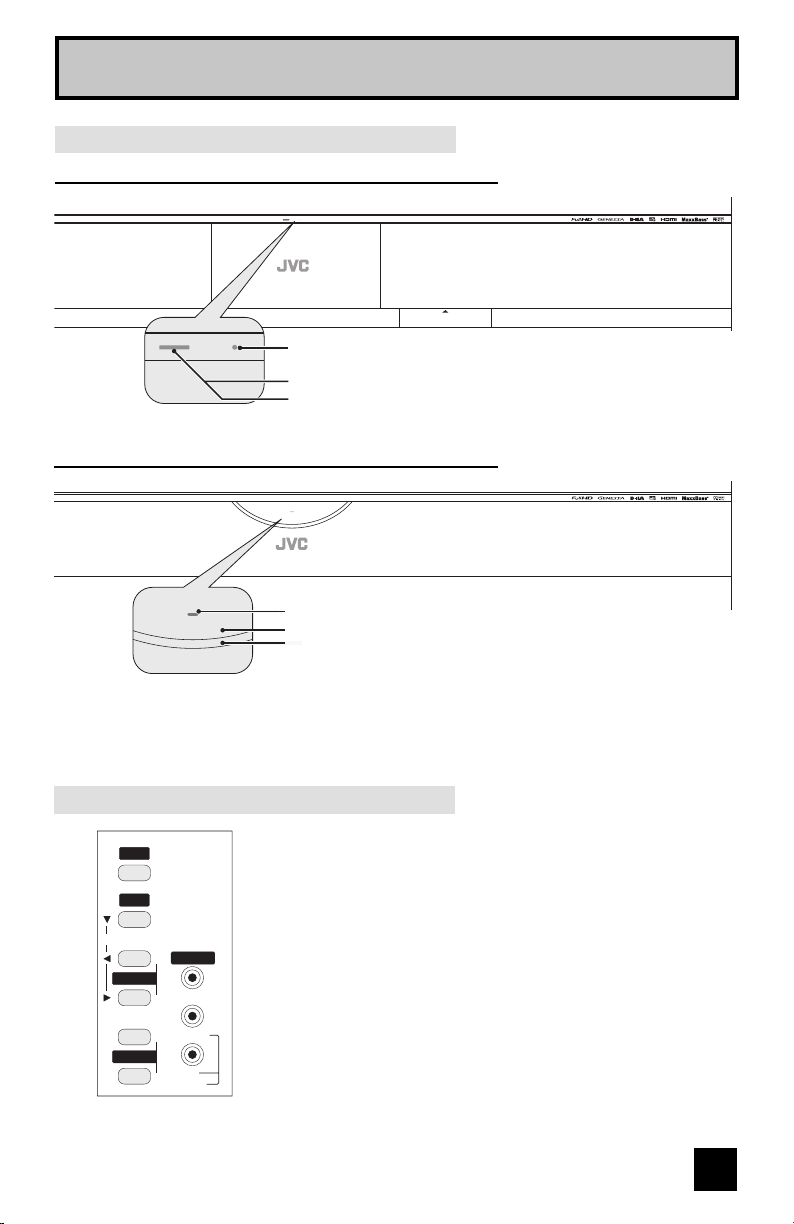
Side Panel Diagram
VOLUME
INPUT 4
CHANNEL
OPERATE
+
–
+
–
MENU
VIDEO
L/MONO
R
AUDIO
INPUT
Front Panel Diagram
LAMP/PROGRAM LED
POWER BUTTON
POWER LED
POWER LAMP/PROGRAM
POWER LAMP/PROGRAM
• For information on the LED, see page 89.
Models: HD-56FC97, HD-61FC97, HD-70FH97, HD-70FN97
POWER
PUSH
LAMP/PROGRAM
POWER
LAMP/PROGRAM
LAMP/PROGRAM LED
POWER BUTTON
POWER LED
PUSH
Models: HD-56FH97, HD-61FH97, HD-56FN97, HD-61FN97
12
Quick Setup
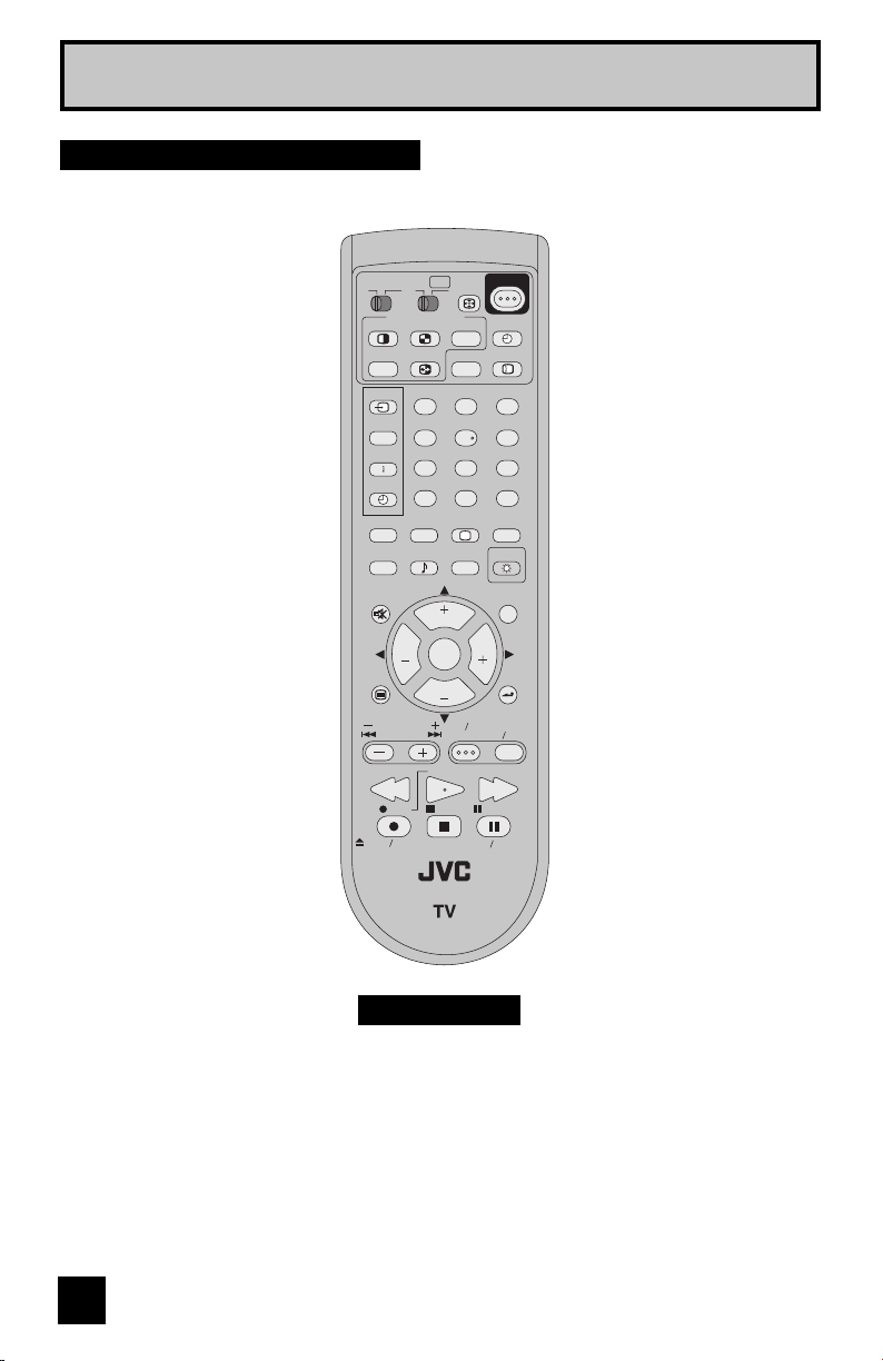
RM-C14G
• For information on remote control buttons, see pages 66 - 82.
• i.LINK MENU, TIMER, SUB CHANNEL and GUIDE buttons are for digital channels. If your
TV is connected to an ATSC antenna or Digital Cable, you can use these buttons.
INPUT
INDEX
ASPECT
FREEZE
SWAP
SELECT
RETURN+
FAVORITE
THEATER
PRO
NATURAL
CINEMA
VIDEO
STATUS
TIMER
i.LINK MENU
SOUND
LIGHT
TV
CATV VCR DVD
MUTING
MENU
BACK
GUIDE
RM-C14G
REW
VCR CHANNEL
PREV NEXT
VCR DVD
POWER
TV VCR
FFPLAY
REC PAUSE
OPEN CLOSE
STILL PAUSE
STOP
CH
CH
VOL VOL
OK
MULTI SCREEN
TWIN
D/A
123
456
789
0
TUNE
TV
POWER
C.C.
SUB
CHANNEL
SUB
ML/MTS
SLEEP
DISPLAY
+
Remote Control
13
These quick setup pages will provide you, in three easy steps, with the basic information you
need to begin using your new television right away. If you have questions, or for more detailed
information on any of these steps, please consult other sections of this manual.
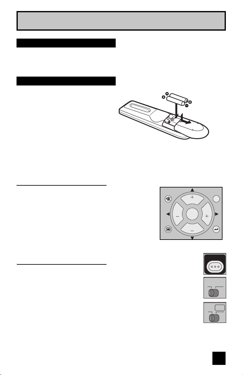
Before you can operate your remote
control, you first need to install the
batteries (included).
Slide the cover on the back of the
remote down towards the bottom of
the remote control. Insert two batteries
(included) carefully noting the “+” and
“–” markings, placing the “–” end in the
unit first. Slide the cover back into place.
When you change the batteries, try to complete the task within three minutes. If you take
longer than three minutes, the remote control codes for your VCR, DVD, and/or cable
box/satellite receiver may have to be reset. See pages 30 - 33.
Quick Setup
Getting Started
Step 1 – The Remote Control
Key Feature Buttons
The four key feature buttons at the center of the remote can be
used for basic operation of the television. The top and bottom
buttons will scan forward and back through the available
channels. To move rapidly through the channels using
JVC’s Hyperscan feature, press and hold CH+ or CH –. The
channels will zip by at a rate of five channels per second. The
right and left buttons will turn the volume up or down. These
buttons are also marked with four arrows and are used with
JVC’s onscreen menu system. To use the onscreen menus,
press the M
ENU button.
MUTING
MENU
BACK
GUIDE
CH
CH
VOL VOL
OK
Basic Operation
Turn the television on and off by pressing the POWER button at the top right corner
of the remote. The POWER LED will light blue. If this is the first time you are
turning on the TV, the interactive plug-in menu appears.
• Make sure the TV/CATV switch is set to TV. Move the switch to CATV only if
you need to operate a cable box.
• Slide the VCR/DVD selector switch to VCR to control a VCR. Slide to
DVD to control a DVD player. Please see pages 30 to 33 for instructions on
programming your remote control to operate a cable box, VCR or DVD player.
POWER
VCR DVD
TV
CATV
Note:
• If the lamp replacement message appears when you turn the television ON, see page 86.
14
Quick Setup
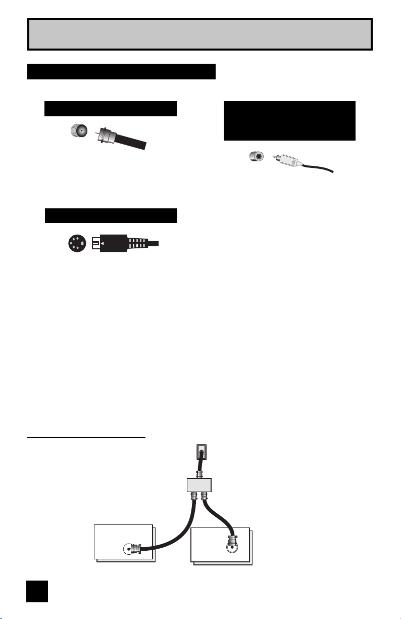
Step 2 – Connecting Your Devices
To make these connections, you will use plugs like the ones illustrated below.
Notes:
• These connections are examples.
• After you are finished connecting your devices, plug the power cord into the nearest power
outlet and turn on the TV.
• If you follow these diagrams and the television does not work properly, contact your local
cable operator.
• To connect a DVD player, see VCR Connection. A DVD player is optional
• If you have a satellite television system, refer to the satellite TV manual.
No VCR Connection
TV Rear Panel
ATSC
/DIGITAL CABLE IN
Coaxial Cable (Attachment)
Cable or Antenna
Output
Two-way Splitter
(Attachment)
75Ω
(VHF/UHF)
IN
OUT OUT
Used to connect an
external antenna or
cable TV system to
your TV.
Used to make video
connections with S-Video
VCRs, Camcorders and
DVD players.
Coaxial Cables
S-Video Cable
Used to connect audio/
video devices like
VCRs, DVD players,
stereo amplifiers, game
consoles, etc.
Component Cables
Composite Cables
Audio Cables
15
Quick Setup
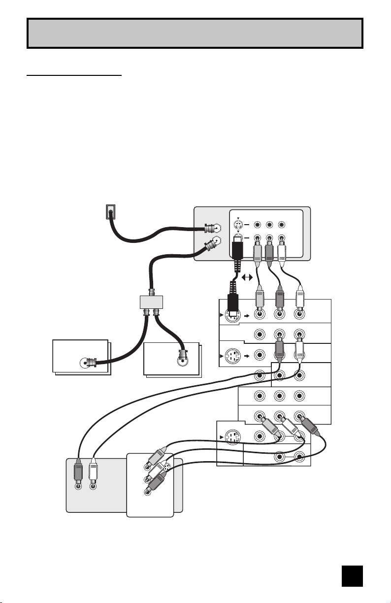
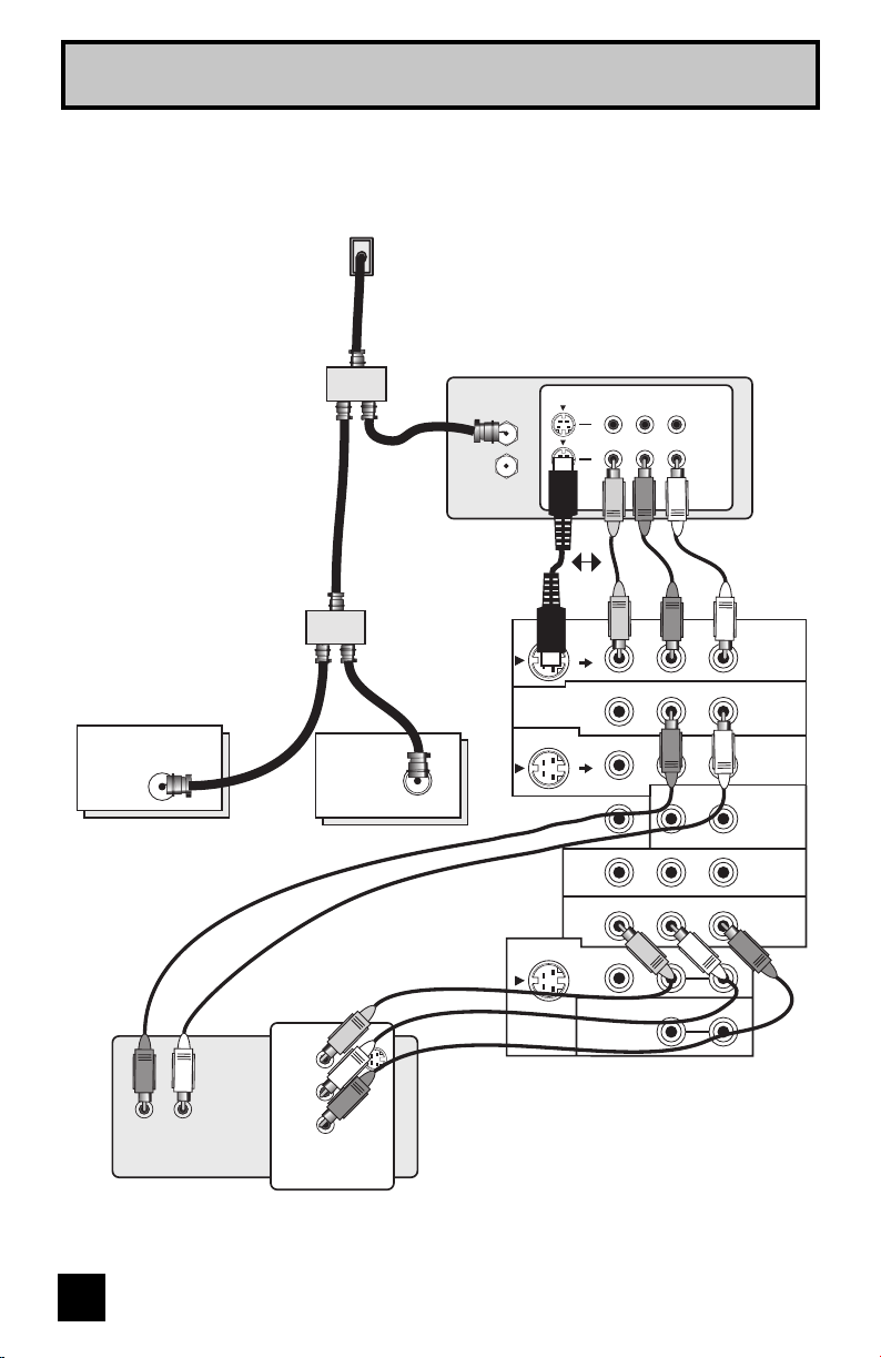
Notes:
• Green, blue and red are the most common colors for DVD cables. Some models may vary
colors. Please consult the user’s manual for your DVD player for more information.
• Be careful not to confuse the red DVD cable with the red audio cable. It is best to complete
one set of connections (DVD or audio output) before starting the other to avoid accidentally
switching the cables.
• You may also connect the DVD player to Input 1.
OVER
CENTER CHANNEL INPUT
INPUT-1
INPUT-2
INPUT-3
HDMI 1
INPUT-1
INPUT-2
VIDEO
VIDEO
VIDEO
R - AUDIO - L
R - AUDIO - L
R - AUDIO - L
R - AUDIO - L
Y Pb Pr
Y Pb Pr
S-VIDEO
S-VIDEO
OVER
VIDEO R L
R L
S-VIDEO
MONITOR
/REC OUT
AUDIO
OUTPUT
Cable or Antenna
Output
Two-Way Splitter
(Attachment)
Coaxial Cable
(Attachment)
Green
Blue
Red
DVD Player (OPTIONAL)
VCR
TV Rear Panel
ATSC
/DIGITAL CABLE IN
I
IN
OUT
V R L
IN
OUT
OR
Y
P
B
P
R
OUT
AUDIO OUT
R L
IN
OUT OUT
75Ω
(VHF/UHF)
Diagram #1
VCR Connection
Note:
• If this connection setup does not work for you, try the connection setup on page 16.
16
Quick Setup
Diagram #2
Cable or Antenna
Output
Two-Way Splitter
Two-Way Splitter
(Attachment)
Coaxial Cable
(Attachment)
Green
Blue
Red
DVD Player (OPTIONAL)
VCR
TV Rear Panel
OR
IN
OUT
IN
OUT OUT
OVER
CENTER CHANNEL INPUT
INPUT-1
INPUT-2
INPUT-3
HDMI 1
INPUT-1
INPUT-2
VIDEO
VIDEO
VIDEO
R - AUDIO - L
R - AUDIO - L
R - AUDIO - L
R - AUDIO - L
Y Pb Pr
Y Pb Pr
S-VIDEO
S-VIDEO
OVER
VIDEO R L
R L
S-VIDEO
MONITOR
/REC OUT
AUDIO
OUTPUT
ATSC
/DIGITAL CABLE IN
I
V R L
IN
OUT
Y
P
B
PR
OUT
AUDIO OUT
R L
IN
OUT OUT
75Ω
(VHF/UHF)
17
Quick Setup
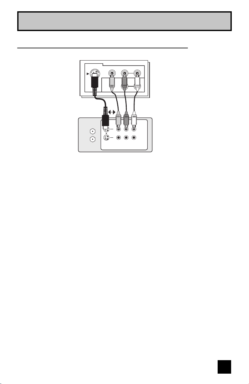
Connecting to Monitor/Recording Output Terminal
Notes:
• When you make this connection, set the Video-1 Monitor Out menu to ON. See page 54.
• If you are receiving ATSC/Digital Cable signal, it can be outputted to the S-Video output
terminal or Video (composite video) terminal.
• If you are receiving Analog TV signal, it can not be outputted to the S-Video output terminal.
• No signal will be outputted through the S-Video output terminal when you are not viewing
images coming from the composite video input terminal.
• No signal will be outputted through the Monitor/Recording output terminal when you are
viewing images from the component video input.
• If you try and record copyright protected programs using a VCR, you will not be able to
record correctly. This is because of the copyright protection system. If you are watching a
copyright protected program using a VCR, the picture will be distorted on the TV. This is due
to the copyright protection system, and is not a malfunction of your TV.
TV Rear Panel
VIDEO R L
R L
S-VIDEO
MONITOR
/REC OUT
AUDIO
OUTPUT
VCR
OR
IN
OUT
V R L
IN
OUT
18
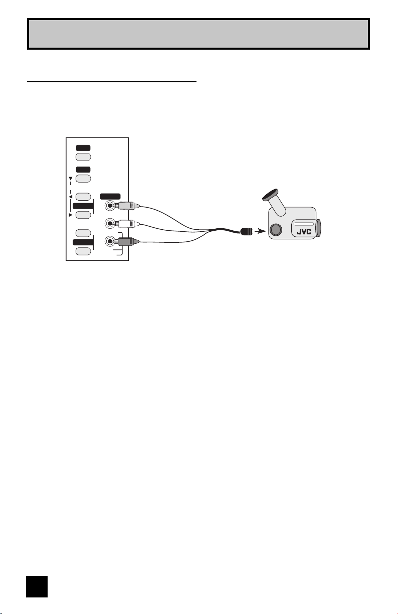
Quick Setup
1) Connect a yellow composite cable from the camcorder VIDEO OUT, into the VIDEO IN on
the side of the TV.
2) Connect a white cable from the camcorder LEFT AUDIO OUT, into the LEFT AUDIO IN on
the side of the TV.
3) Connect a red cable from the camcorder RIGHT AUDIO OUT, into the RIGHT AUDIO IN on
the side of the TV.
Note:
• If your camcorder is a mono sound model it will have only one AUDIO OUT. Connect it to the
L/MONO on the side of the TV.
You may connect a camcorder, game console or other equipment to your television by using
the side input jacks (Input 4) located on the side of the television. You can also connect these
using the television’s rear input jacks, using the same instructions.
VOLUME
INPUT 4
CHANNEL
OPERATE
+
–
+
–
MENU
VIDEO
L/MONO
R
AUDIO
INPUT
CAMCORDER
Connecting to a Camcorder
19
Quick Setup
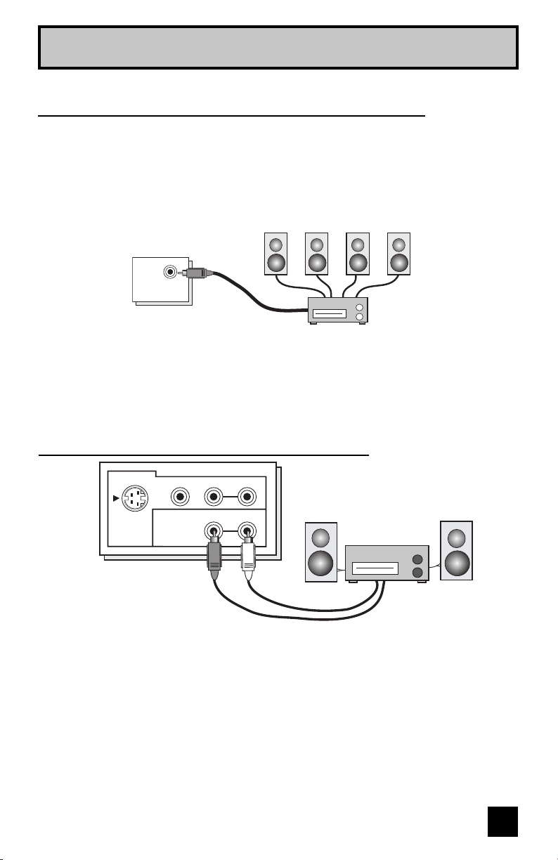
Connecting to the Surround Amplifier
Front
CENTER CHANNEL OUTPUT
(VARIABLE OUTPUT)
TV Rear Panel
Front Surround
CENTER CHANNEL INPUT
1) Connect the Pin cable from the TV's CENTER CHANNEL INPUT terminal to the surround
amplifier's CENTER CHANNEL OUTPUT terminal.
Note:
• Please read the benefit of this feature on page 56.
In multi-channel sound such as 5.1 channel, the speech characters are played back from the
center speaker. A center speaker in a movie theater is set in back of the screen so it can
recreate a conversation scene in the movie more naturally. By using your TV's speaker as
the center speaker, you can obtain the same sound effect as in a movie theater in you home
theater sound system.
TV Rear Panel
Speaker Speaker
Amplifier
VIDEO R L
R L
S-VIDEO
MONITOR
/REC OUT
AUDIO
OUTPUT
1) Connect a white cable from the LEFT AUDIO OUTPUT on the back of the TV to the
LEFT AUDIO INPUT on the amplifier.
2) Connect a red cable from the RIGHT AUDIO OUTPUT on the back of the TV to the
RIGHT AUDIO INPUT on the amplifier.
Notes:
• Refer to your amplifier’s manual for more information.
• You can use AUDIO OUTPUT for your home theater system.
• You can not output audio using the AUDIO OUTPUT under the following conditions:
1) When you have digital sound from an HDMI device connected to the HDMI 1 or HDMI 2
connection on the back of your TV. (See page 22).
2) When you have analog sound from a DVI device connected to the AUDIO IN "HDMI 1"
connection. (See page 21).
Connecting to an External Amplifier
(HD-56FH97, HD-61FH97, HD-70FH97, HD-56FN97, HD-61FN97, HD-70FN97 ONLY)
20
Quick Setup
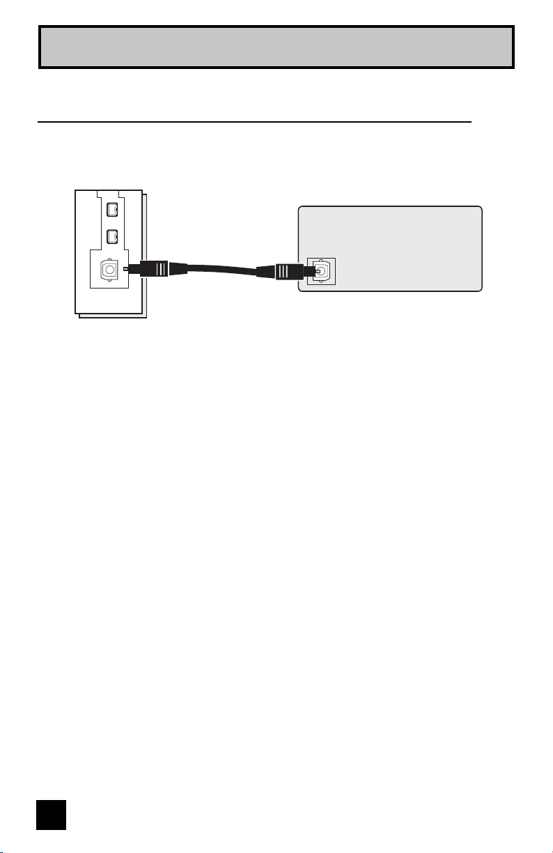
Connecting to an amplifier using your optical output
You can connect an amplifier that has an optical digital input terminal by using an optical digital
cable from the optical output. The signal that is output can be PCM or Dolby Digital.
TV Rear Panel
OPTICAL OUT
Digital Audio
Amplifier
1) Connect the optical cable from the back of the TV to the back of the amplifier.
Notes:
• This terminal can only output digital audio.
• In order to use the optical output connection, select PCM or Dolby Digital on Digital Sound in
the Digital Setup Menu. See page 57.
• Refer to your owners manual on using your amplifier.
21
Quick Setup
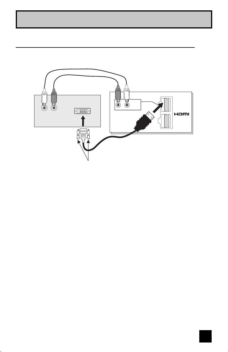
By connecting a Digital TV Receiver, high definition pictures can be displayed on your TV in
their digital form.
DIGITAL-IN
1
2
R - AUDIO - L
HDMI 1
TV Rear Panel
DTV Decoder
HDMI to DVI Cable
After the connections have been made,
tighten the screw to secure the cables.
LR
AUDIO OUT
DIGITAL OUT
Connecting to a Digital TV Receiver
1) Connect the HDMI to DVI Cable from the DIGITAL OUT on the back of your DTV decoder, to
the HDMI1 DIGITAL-IN on the back of your television.
2) Connect a red cable from the "R AUDIO OUT" on the back of your DTV Device, to the
HDMI 1 "R AUDIO" input terminal.
3) Connect a white cable from the "L AUDIO OUT" on the back of your DTV Device, to the
HDMI 1 "L AUDIO" input terminal.
• The digital-in terminal is not compatible with the picture signal of a personal computer.
• Use a HDMI to DVI cable (commercially available) in order to digitally connect the television
with a DTV decoder.
Notes:
• If 480p signals (640x480 or 720x480) are displayed on the screen, the horizontal balance
may be slightly shifted. Access the “DIGITAL-IN” in the initial setup menu to adjust it. (Refer
to page 55.)
• When you do the above connection, set DIGITAL-IN1 AUDIO in the Initial Setup menu to
ANALOG. See "DIGITAL-IN1 AUDIO", page 55.
• The Analog Audio input can only be used with the HDMI 1 input.
• When setting the “DIGITAL AUDIO – ANALOG / DIGITAL” menu setting on the TV, please note
that this setting only effects the HDMI 1 jack and that if you use a DVI to HDMI adapter this
connection must be made to the HDMI 1 along with analog audio cables.
22
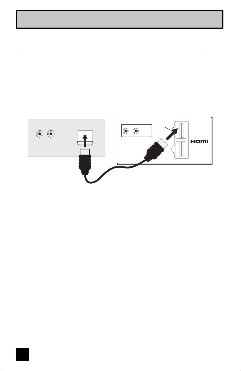
By connecting an HDMI compatible device, high definition pictures can be displayed on your
TV in their digital form. Some HDMI devices can include DVD players, D-VHS or any HDMI
compatible devices.
HDMI (High Definition Multimedia Interface) is the first industry supported, uncompressed, all
digital audio/video interface. HDMI provides and interface between any audio/video source,
such as a set-top box, DVD player, A/V receiver or an audio and/or video monitor, such as a
digital television (DTV).
HDMI Compatible Device
TV Rear Panel
HDMI Cable
LR
AUDIO OUT
DIGITAL OUT
DIGITAL-IN
1
2
R - AUDIO - L
HDMI 1
Quick Setup
Connecting to an HDMI Compatible Device
1) Connect the HDMI Cable from the DIGITAL OUT on the back of your DTV or HDMI device, to
the DIGITAL-IN on the back of your television.
Notes:
• When you do the above connection, set DIGITAL-IN1 AUDIO in the Initial Setup menu to
DIGITAL. See "DIGITAL-IN1 AUDIO", page 55.
• Some decoders may not respond depending on the equipment that you have connected
when it is connected to the HDMI.
• If the HDMI output device signal is changed (for example, 480i/60Hz is changed to
480p/60Hz), the screen may turn green and there may be some distortion for a short time
until the signal becomes stable.
• When you have an HDMI device connected to the HDMI 1 connection on the back of
your TV, your TV detects it, and blocks the analog audio signal coming into the "HDMI 1"
jacks. Therefore, you can not hear any analog sound from the other device conected to the
"HDMI 1" jacks, while you are viewing the images from the HDMI device.
23
Quick Setup
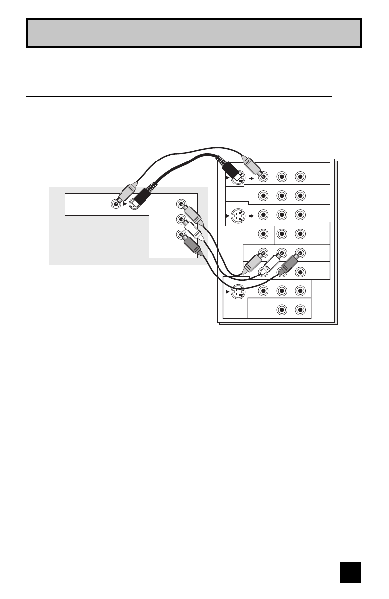
By connecting your AV Receiver to your television's V1 Smart Input, you can watch picture
sources from many different devices, without having to change or use the other input
connections on your TV. This allows you to free up the other input connections so you can
connect more devices to your television.
Connecting to an AV Receiver using your television's
V1 Smart Input
TV Rear Panel
AV Receiver
OVER
CENTER CHANNEL INPUT
INPUT-1
INPUT-2
INPUT-3
HDMI 1
INPUT-1
INPUT-2
VIDEO
VIDEO
VIDEO
R - AUDIO - L
R - AUDIO - L
R - AUDIO - L
R - AUDIO - L
Y Pb Pr
Y Pb Pr
S-VIDEO
S-VIDEO
OVER
VIDEO R L
R L
S-VIDEO
MONITOR
/REC OUT
AUDIO
OUTPUT
MONITOR
OUT
MONITOR OUT
Y
P
B
PR
1) Connect an S-Video Cable from the AV Receiver's MONITOR OUT, to the S-Video INPUT-1
on the back of your television.
2) Connect a Yellow Composite Cable from the AV Receiver's MONITOR OUT, into the VIDEO
INPUT-1 on the back of your television.
3) Connect a Green Component Cable from the AV Receiver's Y MONITOR OUT, into the Y
VIDEO INPUT-1 on the back of your television.
4) Connect a Blue Component Cable from the AV Receiver's P
B MONITOR OUT, into the Pb
VIDEO INPUT-1 on the back of your television.
5) Connect a Red Component Cable from the AV Receiver's PR MONITOR OUT, into the Pr
VIDEO INPUT-1 on the back of your television.
Note:
• Please refer to your AV Receiver instruction manual for more information on connecting your
speakers and other devices like a DVD player.
• Use your AV Receiver's remote to switch to the different devices you have connected.
• Some AV Receivers may not respond when the V1 Smart Input function is turned on.
• If you have video connections for each input device connected to your AV Receiver, you
should not connect them using both S-Video and Composite connection at the same time
when you are using V1 Input as the V1 Smart Input. In this case we recommend using the
S-Video connection.
24
Quick Setup
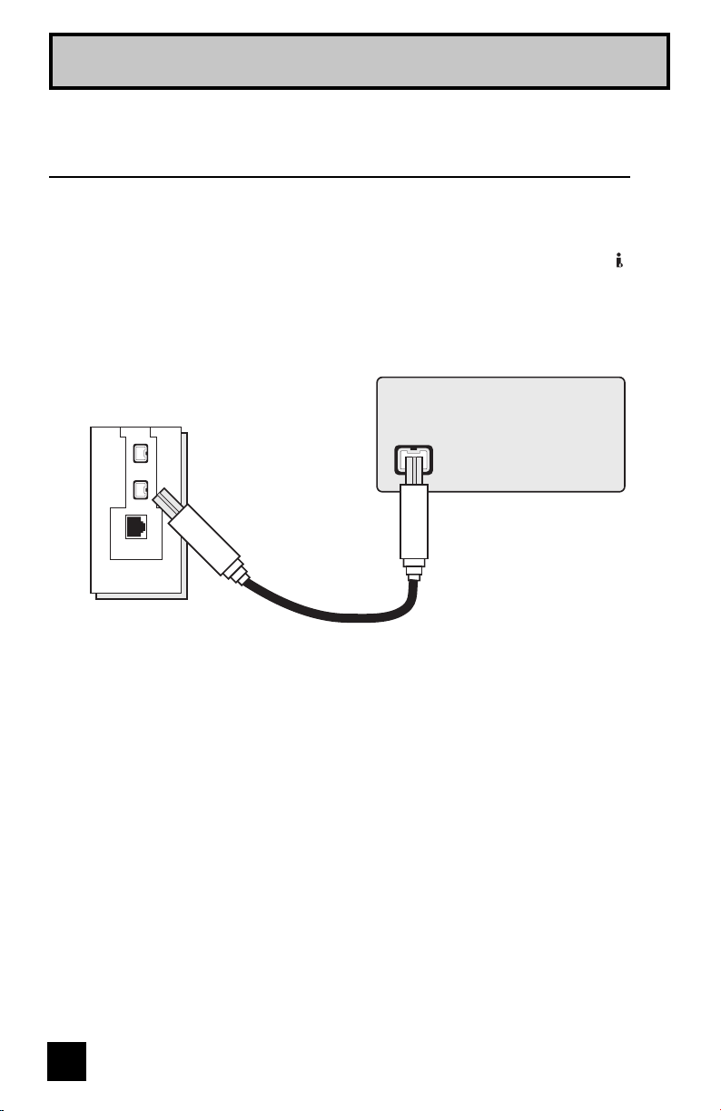
Connecting an i.LINK compatible device to the back of
your television
i.LINK is a digital serial interface that allows devices equipped with an i.LINK connector to
exchange digital video signals, digital audio signals and device control signals bi-directionally
over a single cable. (For example, a JVC D-VHS VCR).
i.LINK refers to the IEEE1394-1995 industry specification and extensions thereof. The logo
is used for products compliant with the i.LINK standard.
This projection television uses a four-pin i.LINK connector to input and output MPEG2 video
signals, audio signals and control signals.
TV Rear Panel
i.LINK Compatible Device
OPTICAL OUT
Digital Audio
1) Connect the i.LINK cable from the back of the TV to the back of the i.LINK compatible
device.
Notes:
• Use only the S400 i.LINK cable when connection your devices.
• See page 58 on how to select the i.LINK device.
• Refer to your owners manual on using your i.LINK device.
• When recording or playing back video with an i.LINK device, if you perform the Auto Tuner
Setup, the video signal you are recording or playing back may stop or you may not be able
to perform the Digital Auto Tuner Setup.
• Your television can connect with i.LINK D-VHS decks and HD-Camcorders (JVC brand only).
If you connect other brand devices, with i.LINK cable, they will not work.
• It can play only the recorded contents in Digital Mode.
• Use only tapes bearing the DVHS (SVHS) mark for recording.
25
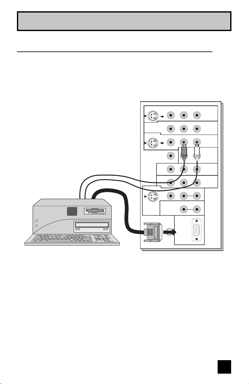
Quick Setup
This TV can be used as a computer screen. Use a commercially available D-SUB cable to
connect the TV's PC INPUT terminal to the computer's analog RGB output terminal. If you
want to listen to the sound from the computer, use a commercially available RCA cable to
connect the INPUT-3 audio input terminal to the computer's audio output terminal.
Connecting to the computer
75Ω
(VHF/UHF)
PC IN
(D-SUB)
INPUT-3
OVER
CENTER CHANNEL INPUT
INPUT-1
INPUT-2
INPUT-3
HDMI 1
INPUT-1
INPUT-2
VIDEO
VIDEO
VIDEO
R - AUDIO - L
R - AUDIO - L
R - AUDIO - L
R - AUDIO - L
Y Pb Pr
Y Pb Pr
S-VIDEO
S-VIDEO
OVER
VIDEO R L
R L
S-VIDEO
MONITOR
/REC OUT
AUDIO
OUTPUT
TV Rear Panel
Notes:
• Refer to your computer manual for a detailed explanation of the connections concerning your
computer.
• Make sure that the connectors are facing the correct way when connecting.
• After connecting, tighten the two screws to fix the connectors in place.
Looking at the images from a computer
After starting the computer, press the INPUT button to choose INPUT-3. You can listen to the
sound when the sound from the computer is connected to the INPUT-3 AUDIO input terminal.
Notes:
• When the sound from the computer is connected to INPUT-3 by choosing external input
INPUT-3, the sound from the computer can be listened to, but the images from the computer
cannot be seen.
(HD-56FH97, HD-61FH97, HD-70FH97, HD-56FN97, HD-61FN97 and HD-70FN97 ONLY)

26
Quick Setup
Table of signals for each type of computer
Resolution
640 x 480
(VGA)
1024 x 768
(XGA)
Vertical
Frequency
(Hz)
60.0
60.0
Horizontal
Frequency
(kHz)
31.5
48.4
When a picture is not displayed
With some computers, some problems can be solved by changing the settings. Check the
computer's refresh rate and set it to 60Hz. Computers that cannot set the refresh rate to 60
Hz, can not be used with this TV. Refer to the computer's instruction manual.
*Apple Macintosh is a registered trademark of Apple Computer, Inc.
Note:
• If you are inputting a PC signal that is invalid, "Invalid Signal" will appear on the TV screen.
It appears when the input is PC and it is a single screen.
• Only the above formats are supported.
• Even with the above formats at 60 Hz, some problems may be experienced depending on
the quality of the synchronous signal. (Depending on the quality, some pictures may not be
displayed correctly).
• Apple Macintosh* computers are not supported.
27
When you turn your television on for the first time the interactive plug-in menu will appear. The
plug-in menu helps you to get your TV ready to use by letting you set your preferences for:
• The language in which you want the onscreen menus to appear.
• Setting the TV’s clock to the correct time so your timer functions will work properly. You can
choose “AUTO” or “MANUAL” for setting the clock.
• The auto tuner setup of which channels you wish to receive.
We recommend you complete the interactive plug-in items before you start using your
television.
Notes:
• The interactive plug-in menu setting does not appear if your TV has been turned on before.
In this case use the onscreen menus to perform these settings. See pages 47, 63, 37.
• If you press the Menu button while setting up the interactive plug-in menu, it will skip over it.
Step 3 – The Interactive Plug In Menu
Quick Setup
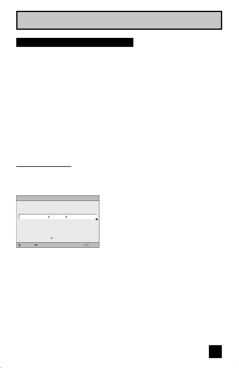
After the “JVC INTERACTIVE PLUG IN MENU” has been displayed, the TV automatically
switches to the LANGUAGE settings. You can choose to view your onscreen menus in three
languages: ENGLISH, FRANÇAIS (French) or ESPAÑOL (Spanish).
è
To choose a language:
ENGLISH, FRANÇAIS or ESPAÑOL
†
To NEXT (To set clock)
Language
(To be continued...)
LANGUAGE/LANGUE/IDIOMA
ENGLISH
NEXT
SELECT OPERATE EXIT
MENU
28
To set your clock manually (without using the XDS signal), choose MANUAL. If you choose
AUTO, see auto clock set above.
è
To choose MANUAL
†
To TIME
è
To set the hour
†
To minute
è
To set the minute
†
To TIME ZONE
è
To select your time zone: (Atlantic, Eastern,
Central, Mountain, Pacific, Alaska or Hawaii)
†
To DATE/YEAR
è
To set the month
†
To day
è
To set the day
†
To year
è
To set the year
†
To move to D.S.T. (Daylight Savings Time)
è
To turn D.S.T. ON or OFF
†
To START CLOCK
Manual Clock Set
Note:
• You will have to reset the clock after a power interruption. You must set the clock before
operating any timer functions.
Quick Setup
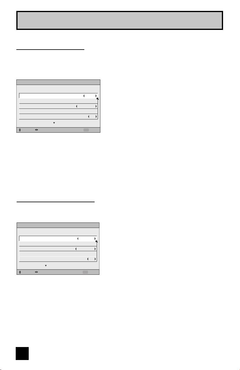
Before you use any of your TV’s timer functions, you must first set the clock. You may
precisely set your clock using the XDS time signal broadcast by most public analog
broadcasting stations. If you do not have this in your area, you will have to set the clock
manually. See manual clock set below. To set the clock using the XDS signal:
è
To choose AUTO
†
To TIME ZONE
è
To select your time zone: (Atlantic, Eastern,
Central, Mountain, Pacific, Alaska or Hawaii)
†
To move to D.S.T. (Daylight Savings Time)
è
To turn D.S.T. ON or OFF
†
To NEXT (To Auto Tuner Setup)
Notes:
• D.S.T. can be used when it is set to ON in the SET CLOCK menu.
• Only when the MODE is set to AUTO, the Daylight Savings Time feature automatically
adjusts your TV’s clock for Daylight Savings. The clock will move forward one hour at 2:00
am on the first Sunday in April. The clock will move back one hour at 2:00 am on the last
Sunday in October.
• You will have to reset the clock after a power interruption. You must set the clock before
operating any timer functions.
Auto Clock Set
(To be continued...)
SET CLOCK
SELECT OPERATE EXIT
MENU
TIME
MODE
TIME ZONE
DATE/YEAR
D.S.T.
MANUAL
--
:
--
--
ATLANTIC
JAN/01/06
ON
START CLOCK
SET CLOCK
NEXT
SELECT OPERATE EXIT
MENU
TIME
--
:
--
--
MODE
TIME ZONE
DATE/YEAR
D.S.T.
AUTO
ATLANTIC
JAN/01/06
ON
29
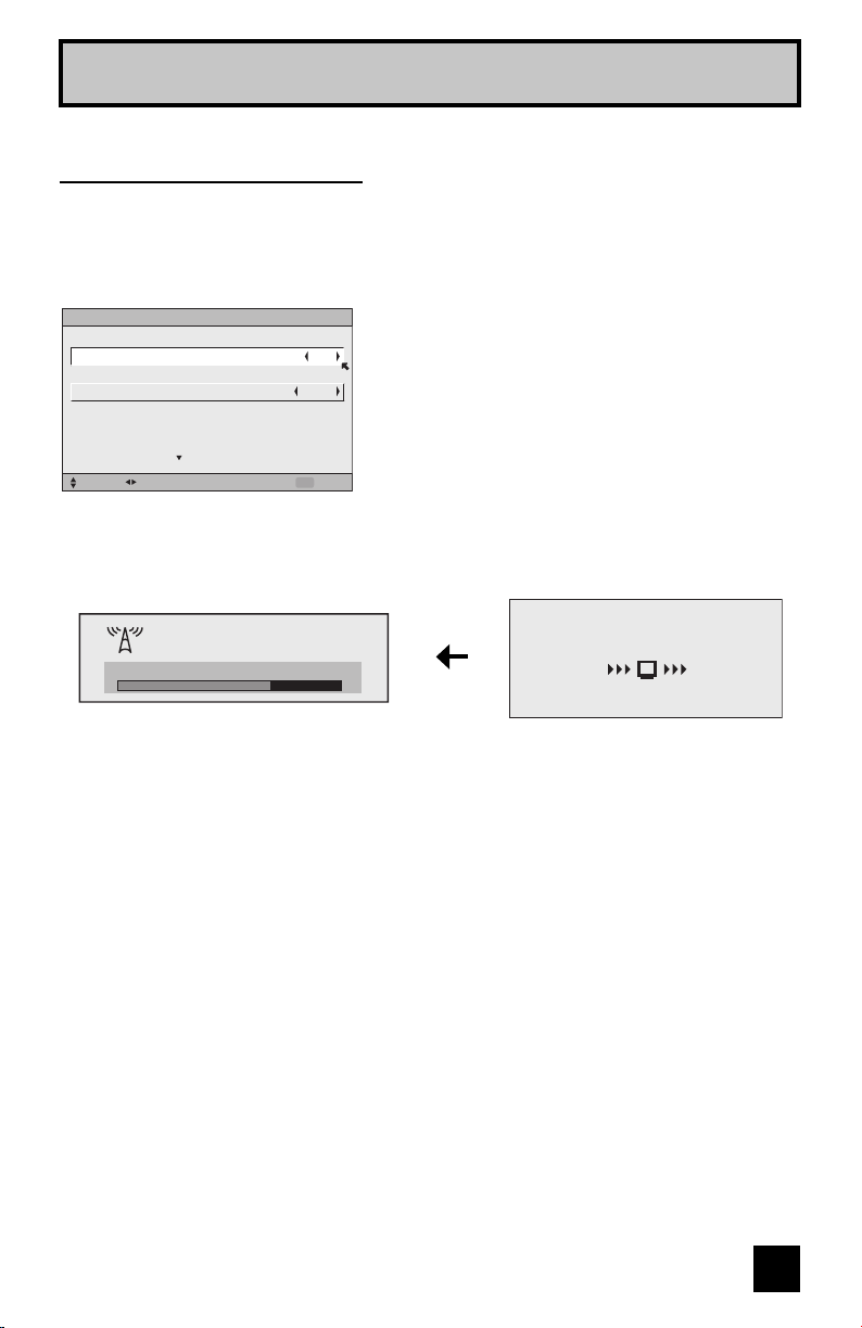
Quick Setup
In auto tuner setup, the TV automatically scans through all available channels, memorizing the
active ones and skipping over blank ones or channels with weak signals. This means when you
scan (using the C
HANNEL +/– buttons) you will receive only clear, active channels. There are
two tuner modes to choose from, ANALOG or DIGITAL.
è
To choose CABLE or AIR (or SKIP when
you skip Analog Auto Tuner Setup)
π†
To TUNER MODE (IN DIGITAL)
è
To choose ATSC or Digital Cable (or SKIP
when you skip Digital Auto Tuner Setup)
†
To START
After Analog Auto Tuner Setup is finished, Digital Auto
Tuner Setup starts.
Auto Tuner Setup
When the setup is finished, "THANK YOU ! SETUP IS NOW COMPLETE" is displayed. Your
quick setup is now complete. You can now begin watching your television, or you can continue
on in this guide for more information on programming your remote control, or using the
JVC onscreen menu system to customize your television viewing experience.
Notes:
• If you want to cancel the Auto Tuner Setup, press the MENU button.
• Noise muting will not work during Auto Tuner Setup.
• If you choose SKIP, it finished without doing the Auto Tuner Setup.
Cable Box and Satellite Users: After your auto tuner setup is complete, you may, (depending
on the type of hookup), have only 1 channel, usually 3 or 4 in the auto tuner memory. This is
normal.
AUTO TUNER SETUP
SELECT OPERATE EXIT
MENU
IN ANALOG
IN DIGITAL
ATSC
TUNER MODE
AIRTUNER MODE
START
48
NOW
PROGRAMMING !
20
Now Programming...
Loading...