


 Loading...
R
SERVICE MANUAL
HD CAMERA RECORDER
GY-HD100U/GY-HD100E
GY-HD101E
GY-HD101E is added only the DV input function to GY-HD100E.
Note
s Lead free solder used in the board (material : Sn, Ag, In, Bi, melting point : 227 Centigrade)
100% recycled paper |
COPYRIGHT © 2005 Victor Company of Japan, Limited |
No. HC009
Aug. 2005
TABLE OF CONTENTS
Section |
Title |
Page |
|
Important Safety Precautions |
|
||
INSTRUCTIONS |
|
||
SECTION 1 SERVICE CAUTIONS AND DISASSEMBLY |
|
||
1.1 |
HOW TO REMOVE THE COSMETIC PARTS ........................... |
1-1 |
|
1.1.1 |
Left side cover ................................................................... |
1-1 |
|
1.1.2 |
Right side cover ................................................................. |
1-1 |
|
1.2 |
HOW TO REMOVE THE OPTICAL BLOCK ASSEMBLY .......... |
1-2 |
|
1.3 |
HOW TO REMOVE VCR UNIT ................................................. |
1-3 |
|
1.3.1 |
Mechanism unit ................................................................. |
1-3 |
|
1.3.2 |
Cassette housing ............................................................... |
1-4 |
|
1.4 |
HOW TO REMOVE THE MAJOR BOARDS ............................. |
1-5 |
|
1.4.1 |
Audio board ........................................................................ |
1-5 |
|
1.4.2 |
LCD monitor ....................................................................... |
1-5 |
|
1.4.3 |
MIF board .......................................................................... |
1-6 |
|
1.4.4 |
MAIN board ........................................................................ |
1-6 |
|
1.4.5 |
HANDLE assembly ............................................................ |
1-6 |
|
1.4.6 |
PS board ............................................................................. |
1-8 |
|
1.5 |
SERVICE MENUS ..................................................................... |
1-8 |
|
1.5.1 Modes required in servicing ............................................... |
1-8 |
||
1.5.2 Operation in the first-level of the service menu ................. |
1-8 |
||
1.5.3 CAMERA 1 menu ............................................................... |
1-9 |
||
1.5.4 CAMERA 2 menu ............................................................. |
1-10 |
||
1.5.5 CAMERA 3 menu ............................................................. |
1-11 |
||
1.5.6 |
VTR 1 menu ..................................................................... |
1-11 |
|
1.5.7 |
VTR 2 menu ..................................................................... |
1-12 |
|
1.5.8 |
VTR 3 menu ..................................................................... |
1-12 |
|
1.5.9 |
DIP SW menu .................................................................. |
1-13 |
|
1.5.10 HOUR METER ................................................................ |
1-15 |
||
1.5.11 ERROR HISTORY ........................................................... |
1-15 |
||
1.5.12 Detail indication of ERROR HISTORY ............................. |
1-15 |
||
1.5.13 OTHERS menu ............................................................... |
1-19 |
||
1.5.14 CPU version menu .......................................................... |
1-20 |
||
1.5.15 EEP-ROM ........................................................................ |
1-20 |
||
1.6 |
HOW TO UPDATE FIRMWARE .............................................. |
1-22 |
|
1.6.1 |
Preparation (Copy firmware to SD memory card) ............ |
1-22 |
|
1.6.2 |
Update procedure ............................................................ |
1-22 |
|
SECTION 2 MECHANICAL ADJUSTMENTS |
|
||
2.1 |
BEFORE ADJUSTMENTS ........................................................ |
2-1 |
|
2.1.1 |
Precautions ........................................................................ |
2-1 |
|
2.1.2 Measuring instruments required for adjustments ............. |
2-1 |
||
2.1.3 Equipment required for adjustments ................................. |
2-1 |
||
2.2 |
BASICS OF MECHANISM DISASSAMBLY/ASSEMBLY .......... |
2-2 |
|
2.2.1 |
Assembly mode ................................................................. |
2-2 |
|
2.3 |
MECHANISM TIMING CHART ................................................. |
2-3 |
|
2.4 |
MAINTENANCE AND INSPECTION OF MAJOR PARTS .......... |
2-4 |
|
2.4.1 Layout of major parts ......................................................... |
2-4 |
||
2.4.2 Maintenance and inspection list ........................................ |
2-5 |
||
2.4.3 |
Cleaning ............................................................................. |
2-6 |
|
2.4.4 |
Oiling and greasing ............................................................ |
2-6 |
|
2.5 |
PERIODICAL MAINTENANCE .................................................. |
2-7 |
|
2.6 |
DISASSEMBLY/ASSEMBLY OF MECHANISM ASSEMBLY ..... |
2-8 |
|
2.6.1 |
Assembly/disassembly ...................................................... |
2-8 |
|
2.6.2 |
Screws and washers used in mechanism assembly |
|
|
|
|
disassembly/assembly ....................................................... |
2-8 |
2.6.3 |
Mechanism assembly disassembly procedure table ......... |
2-9 |
|
2.6.4 |
Mechanism disassembly/assembly procedure chart ....... |
2-10 |
|
2.7 |
REPLACEMENT OF MAJOR PARTS ...................................... |
2-11 |
|
2.8 |
CONFIRMATION AND ADJUSTMENT OF MECHANISM PHASES ..... |
2-22 |
|
2.9 |
DISASSEMBLY PROCEDURE LIST ........................................ |
2-23 |
|
2.10 MECHANISM DISASSEMBLY/ASSEMBLY SHEET ............... |
2-24 |
||
2.11 TORQUE ADJUSTMENTS .................................................... |
2-26 |
||
2.12 COMPATIBILITY ADJUSTMENT ........................................... |
2-27 |
||
2.12.1 Compatibility adjustment flow chart ............................... |
2-27 |
||
2.12.2 Tape transport restriction ................................................ |
2-28 |
||
2.12.3 Compatibility adjustment ................................................ |
2-29 |
||
Section Title Page
SECTION 3 ELECTRICAL ADJUSTMENTS
3.1 |
FUNCTIONS REQUIRED FOR ADJUSTMENTS, SETUP |
.......... 3-1 |
|
3.1.1 General instruments necessary for adjustment ................. |
3-1 |
||
3.1.2 Special implements required for adjustment ..................... |
3-1 |
||
3.2 |
STANDARD SETUP .................................................................. |
3-2 |
|
3.3 |
ADJUSTMENT MENU .............................................................. |
3-4 |
|
3.3.1 |
Switches and Functions Used in Adjustments .................. |
3-4 |
|
3.3.2 |
Procedure ........................................................................... |
3-4 |
|
3.3.3 |
Adjustment mode .............................................................. |
3-4 |
|
3.4 |
CAMERA ADJUSTMENTS ....................................................... |
3-5 |
|
3.4.1 |
Camera adjustments .......................................................... |
3-5 |
|
3.4.2 |
AUDIO adjustment ........................................................... |
3-13 |
|
3.4.3 |
MONITOR LCD adjustment ............................................. |
3-14 |
|
3.4.4 |
VIEWFINDER adjustment ................................................ |
3-16 |
|
3.5 |
DVC UNIT ADJUSTMENTS .................................................... |
3-18 |
|
SECTION 4 CHARTS AND DIAGRAMS
4.1 |
INDEX TO PAGES OF MAIN BOARDS AND |
|
|
|
|
CIRCUIT BOARD LOCATION ................................................... |
4-3 |
4.1.1 Circuit board location ......................................................... |
4-3 |
||
4.2 |
GY-HD100 BLOCK DIAGRAM .................................................. |
4-4 |
|
4.3 |
CAMERA PROCESS BLOCK DIAGRAM .................................. |
4-5 |
|
4.4 |
|
OVERALL WIRING DIAGRAM ................................................. |
4-6 |
4.5 |
|
ISG SCHEMATIC DIAGRAM .................................................... |
4-7 |
4.6 |
|
ISB SCHEMATIC DIAGRAM ..................................................... |
4-8 |
4.7 |
|
ISR SCHEMATIC DIAGRAM ..................................................... |
4-9 |
4.8 |
ISG, ISB, ISR CIRCUIT BOARDS ............................................ |
4-10 |
|
4.9 |
|
MAIN SCHEMATIC DIAGRAM ............................................... |
4-11 |
4.10 |
MAIN CIRCUIT BOARD ........................................................ |
4-29 |
|
4.11 |
MIF & PS CIRCUIT BOARDS ............................................... |
4-30 |
|
4.12 |
MIF SCHEMATIC DIAGRAMS .............................................. |
4-31 |
|
4.13 |
PS SCHEMATIC DIAGRAM ................................................... |
4-38 |
|
4.14 |
PRMDA CIRCUIT BOARD ..................................................... |
4-39 |
|
4.15 |
PRMDA SCHEMATIC DIAGRAMS (1/3) ................................ |
4-40 |
|
4.16 |
AUDIO CIRCUIT BOARD ...................................................... |
4-43 |
|
4.17 |
AUDIO SCHEMATIC DIAGRAMS (1/2) ................................. |
4-44 |
|
4.18 |
LINE SELECT SCHEMATIC DIAGRAM ................................. |
4-46 |
|
4.19 |
LINE SELECT CIRCUIT BOARDS .......................................... |
4-47 |
|
4.20 |
OPERATION-1 & ETC (MOS, DVOUT, VJK, EAR, |
|
|
|
|
DC IN& SD) SCHEMATIC DIAGRAMS .................................. |
4-48 |
4.21 |
OPERATION-1 & ETC (MOS, DVOUT, VJK, EAR, |
|
|
|
|
DC IN& SD) CIRCUIT BOARDS ............................................. |
4-49 |
4.22 |
OPERATION-2 (AVR, STA, SWP, MNU, OPE, EJT, |
|
|
|
|
AWB & XLR) SCHEMATIC DIAGRAMS ................................ |
4-50 |
4.23 |
OPERATION-2 (AVR, STA, SWP, MNU, OPE, EJT, |
|
|
|
|
AWB & XLR) CIRCUIT BOARDS ........................................... |
4-51 |
4.24 |
OPERATION-3 (FTY, USR, FRL, PBM, AJK, FNC & ZBR) |
|
|
|
|
& MECHA CONNECTOR SCHEMATIC DIAGRAMS ............. |
4-52 |
4.25 |
OPERATION-3 (FTY, USR, FRL, PBM, AJK, FNC & ZBR) |
|
|
|
|
& MECHA CONNECTOR CIRCUIT BOARDS ........................ |
4-53 |
4.26 |
VF IF SCHEMATIC DIAGRAM ............................................... |
4-54 |
|
4.27 |
VF IF & VF_DR CIRCUIT BOARDS ........................................ |
4-55 |
|
4.28 |
VF DR SCHEMATIC DIAGRAM ............................................. |
4-56 |
|
4.29 |
M BL SCHEMATIC DIAGRAM .............................................. |
4-57 |
|
4.30 |
M BL CIRCUIT BOARDS ....................................................... |
4-58 |
|
4.31 |
IC BLOCK DIAGRAMS .......................................................... |
4-59 |
|
SECTION 5 EXPLODED VIEW AND PARTS LIST
5.1 |
CABINET ASSEMBLY M2 ....................................................... |
5-2 |
5.2 |
CHASSIS ASSEMBLY M3 ....................................................... |
5-4 |
5.3 |
RIGHT SIDE COVER ASSEMBLY M4...................................... |
5-6 |
5.4 |
MONITOR LCD ASSEMBLY M5 ............................................. |
5-7 |
5.5 |
HANDLE ASSEMBLY M6 ....................................................... |
5-8 |
5.6 |
VF ASSEMBLY M7 ................................................................ |
5-10 |
5.7 |
MECHANISM ASSEMBLY M8 .............................................. |
5-12 |
Section Title Page
SECTION 6 ELECTRICAL PARTS LIST
6.1 |
ISB BOARD ASSEMBLY PARTS LIST 01 ............................... |
6-2 |
6.2 |
ISG BOARD ASSEMBLY PARTS LIST 02............................... |
6-3 |
6.3 |
ISR BOARD ASSEMBLY PARTS LIST 03 ............................... |
6-4 |
6.4 |
MAIN BOARD ASSEMBLY PARTS LIST 10 ........................... |
6-5 |
6.5 |
MIF BOARD ASSEMBLY PARTS LIST 20 |
|
|
(GY-HD100U/100E) ................................................................. |
6-13 |
6.6 |
MIF BOARD ASSEMBLY PARTS LIST 20 (GY-HD101E) ...... |
6-16 |
6.7 |
PS BOARD ASSEMBLY PARTS LIST 21 .............................. |
6-20 |
6.8 |
AUDIO BOARD ASSEMBLY PARTS LIST 30 ....................... |
6-22 |
6.9 |
LINSEL BOARD ASSEMBLY PARTS LIST 31 ...................... |
6-24 |
6.10 SD BOARD ASSEMBLY PARTS LIST 32.............................. |
6-25 |
|
6.11 PRMDA BOARD ASSEMBLY PARTS LIST 33 ..................... |
6-25 |
|
6.12 VF DR BOARD ASSEMBLY PARTS LIST 34 ........................ |
6-27 |
|
6.13 MOS BOARD ASSEMBLY PARTS LIST 35 .......................... |
6-28 |
|
6.14 DC IN BOARD ASSEMBLY PARTS LIST 41 ......................... |
6-28 |
|
6.15 VJK BOARD ASSEMBLY PARTS LIST 42 ............................ |
6-28 |
|
6.16 DV OUT BOARD ASSEMBLY PARTS LIST 43 ..................... |
6-28 |
|
6.17 EAR BOARD ASSEMBLY PARTS LIST 44 ........................... |
6-28 |
|
6.18 MNU BOARD ASSEMBLY PARTS LIST 51 .......................... |
6-29 |
|
6.19 OPE BOARD ASSEMBLY PARTS LIST 52 ........................... |
6-29 |
|
6.20 EJT BOARD ASSEMBLY PARTS LIST 53 ............................ |
6-29 |
|
6.21 VF IF BOARD ASSEMBLY PARTS LIST 54 .......................... |
6-29 |
|
6.22 AWB BOARD ASSEMBLY PARTS LIST 55 .......................... |
6-29 |
|
6.23 XLR BOARD ASSEMBLY PARTS LIST 56 ............................ |
6-30 |
|
6.24 SWP BOARD ASSEMBLY PARTS LIST 57 .......................... |
6-30 |
|
6.25 STA BOARD ASSEMBLY PARTS LIST 58 ............................ |
6-30 |
|
6.26 AVR BOARD ASSEMBLY PARTS LIST 59 ............................ |
6-31 |
|
6.27 MON BL BOARD ASSEMBLY PARTS LIST 61 .................... |
6-31 |
|
6.28 FTY BOARD ASSEMBLY PARTS LIST 62 ............................ |
6-31 |
|
6.29 USR BOARD ASSEMBLY PARTS LIST 63 ........................... |
6-31 |
|
6.30 FRL BOARD ASSEMBLY PARTS LIST 64 ............................ |
6-31 |
|
6.31 PBM BOARD ASSEMBLY PARTS LIST 65 .......................... |
6-32 |
|
6.32 ZBR BOARD ASSEMBLY PARTS LIST 66............................ |
6-32 |
|
6.33 A.JACK BOARD ASSEMBLY PARTS LIST 67 ...................... |
6-32 |
|
6.34 FNC BOARD ASSEMBLY PARTS LIST 68 ........................... |
6-32 |
|
6.35 M.CONN. BOARD ASSEMBLY PARTS LIST 70................... |
6-32 |
|
6.36 TERM. BOARD ASSEMBLY PARTS LIST 80 ....................... |
6-32 |
|
SECTION 7 PACKING
7.1 PACKING ASSEMBLY M1 ...................................................... |
7-1 |
SECTION 8 TECHNICAL INFORMATION
8.1 HDV FORMAT .......................................................................... |
8-1 |
|
8.1.1 |
HDV Features ..................................................................... |
8-1 |
8.1.2 |
HD Image Format .............................................................. |
8-1 |
8.1.3 |
Progressive method ........................................................... |
8-1 |
8.1.4 |
Comparison of HDV format and DV format ....................... |
8-2 |
8.1.5 |
Tape Format ....................................................................... |
8-3 |
8.1.6 GY-HD100 & BR-HD50 Compatible Format ....................... |
8-3 |
|
8.2 RECORDING SIGNAL SYNTAX .................................................. |
8-4 |
|
8.2.1 |
720/30P .............................................................................. |
8-4 |
8.2.2 |
720/24P .............................................................................. |
8-4 |
8.2.3 |
720/25P .............................................................................. |
8-4 |
8.3 VIDEO CIRCUIT ........................................................................ |
8-5 |
|
8.3.1 |
CCD .................................................................................... |
8-5 |
8.3.2 |
VIDEO Signals .................................................................... |
8-6 |
8.3.3 |
AUDIO Signals ................................................................... |
8-8 |
8.3.4 SYSTEM CONTROL ......................................................... |
8-10 |
|
8.4 GLOSSARY ............................................................................. |
8-11 |
|
Important Safety Precautions
Prior to shipment from the factory, JVC products are strictly inspected to conform with the recognized product safety and electrical codes of the countries in which they are to be sold. However, in order to maintain such compliance, it is equally important to implement the following precautions when a set is being serviced.
Precautions during Servicing
1.Locations requiring special caution are denoted by labels and inscriptions on the cabinet, chassis and certain parts of the product. When performing service, be sure to read and comply with these and other cautionary notices appearing in the operation and service manuals.
2.Parts identified by the  symbol and shaded (
 ) parts are critical for safety.
Replace only with specified part numbers.
Note: Parts in this category also include those specified to comply with X-ray emission standards for products using cathode ray tubes and those specified for compliance with various regulations regarding spurious radiation emission.
3.Fuse replacement caution notice.
Caution for continued protection against fire hazard. Replace only with same type and rated fuse(s) as specified.
4.Use specified internal wiring. Note especially:
1)Wires covered with PVC tubing
2)Double insulated wires
3)High voltage leads
5.Use specified insulating materials for hazardous live parts. Note especially:
1) |
Insulation Tape |
3) |
Spacers |
5) Barrier |
2) |
PVC tubing |
4) |
Insulation sheets for transistors |
|
6.When replacing AC primary side components (transformers, power cords, noise blocking capacitors, etc.) wrap ends of wires securely about the terminals before soldering.
Fig.1
7.Observe that wires do not contact heat producing parts (heatsinks, oxide metal film resistors, fusible resistors, etc.)
8.Check that replaced wires do not contact sharp edged or pointed parts.
9.When a power cord has been replaced, check that 10-15 kg of force in any direction will not loosen it.
Power cord
Fig.2
10.Also check areas surrounding repaired locations.
11.Products using cathode ray tubes (CRTs)
In regard to such products, the cathode ray tubes themselves, the high voltage circuits, and related circuits are specified for compliance with recognized codes pertaining to X-ray emission. Consequently, when servicing these products, replace the cathode ray tubes and other parts with only the specified parts. Under no circumstances attempt to modify these circuits.
Unauthorized modification can increase the high voltage value and cause X-ray emission from the cathode ray tube.
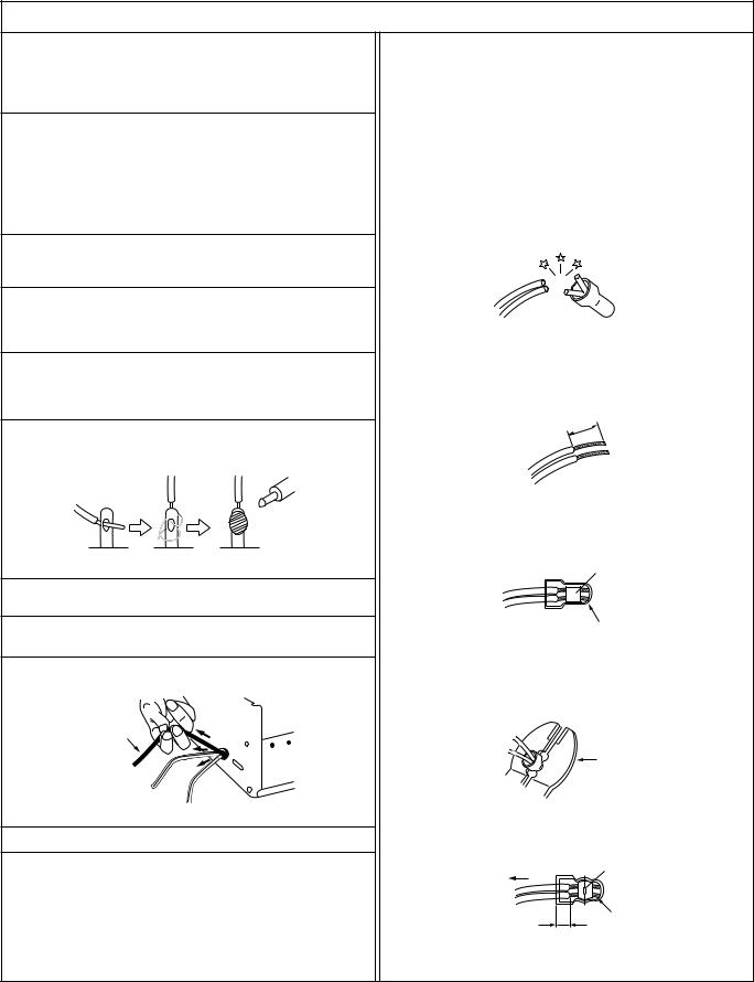
12.Crimp type wire connector
In such cases as when replacing the power transformer in sets where the connections between the power cord and power transformer primary lead wires are performed using crimp type connectors, if replacing the connectors is unavoidable, in order to prevent safety hazards, perform carefully and precisely according to the following steps.
1)Connector part number : E03830-001
2)Required tool : Connector crimping tool of the proper type which will not damage insulated parts.
3)Replacement procedure
(1)Remove the old connector by cutting the wires at a point close to the connector.
Important : Do not reuse a connector (discard it).
cut close to connector
Fig.3
(2)Strip about 15 mm of the insulation from the ends of the wires. If the wires are stranded, twist the strands to avoid frayed conductors.
15 mm
Fig.4
(3)Align the lengths of the wires to be connected. Insert the wires fully into the connector.
Metal sleeve
Connector
Fig.5
(4)As shown in Fig.6, use the crimping tool to crimp the metal sleeve at the center position. Be sure to crimp fully to the complete closure of the tool.
25 |
Crimping tool |
1. |
|
2. |
|
0 |
|
5. |
|
5 |
|
Fig.6
(5) Check the four points noted in Fig.7.
Not easily pulled free |
Crimped at approx. center |
|
|
of metal sleeve |
|
|
|
|
|
|
Conductors extended |
Wire insulation recessed |
|
|
more than 4 mm |
|
|
Fig.7
1
Safety Check after Servicing
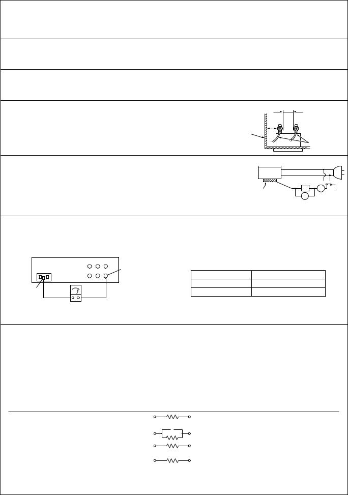
Examine the area surrounding the repaired location for damage or deterioration. Observe that screws, parts and wires have been returned to original positions, Afterwards, perform the following tests and confirm the specified values in order to verify compliance with safety standards.
1.Insulation resistance test
Confirm the specified insulation resistance or greater between power cord plug prongs and externally exposed parts of the set (RF terminals, antenna terminals, video and audio input and output terminals, microphone jacks, earphone jacks, etc.). See table 1 below.
2.Dielectric strength test
Confirm specified dielectric strength or greater between power cord plug prongs and exposed accessible parts of the set (RF terminals, antenna terminals, video and audio input and output terminals, microphone jacks, earphone jacks, etc.). See table 1 below.
3.Clearance distance
When replacing primary circuit components, confirm specified clearance distance (d), (d’) between soldered terminals, and between terminals and surrounding metallic parts. See table 1 below.
Chassis
Fig. 8
d |
d' |
Power cord, |
primary wire |
4.Leakage current test
Confirm specified or lower leakage current between earth ground/power cord plug prongs and externally exposed accessible parts (RF terminals, antenna terminals, video and audio input and output terminals, microphone jacks, earphone jacks, etc.).
Measuring Method : (Power ON)
Insert load Z between earth ground/power cord plug prongs and externally exposed accessible parts. Use an AC voltmeter to measure across both terminals of load Z. See figure 9 and following table 2.
a
 b
b
Z A c 
Externally exposed V
accessible part
Fig. 9
5.Grounding (Class 1 model only)
Confirm specified or lower grounding impedance between earth pin in AC inlet and externally exposed accessible parts (Video in, Video out, Audio in, Audio out or Fixing screw etc.).
Measuring Method:
Connect milli ohm meter between earth pin in AC inlet and exposed accessible parts. See figure 10 and grounding specifications.
AC inlet |
Grounding Specifications |
|
Exposed accessible part |
Grounding Impedance (Z) |
|
|
Region |
|
|
USA & Canada |
Z ≤ 0.1 ohm |
Earth pin |
Europe & Australia |
Z ≤ 0.5 ohm |
Milli ohm meter
Fig. 10
AC Line Voltage |
Region |
Insulation Resistance (R) |
Dielectric Strength |
Clearance Distance (d), (d') |
||||||||||
|
|
|
|
|
|
|
|
|
|
|
|
|||
100 V |
Japan |
R |
≤ |
1 MΩ/500 V DC |
AC 1 kV 1 minute |
|
d, d' |
≤ |
3 mm |
|||||
100 to 240 V |
AC 1.5 kV 1 miute |
|
d, d' |
≤ |
4 mm |
|||||||||
|
|
|||||||||||||
|
|
|
|
|
|
|
||||||||
|
|
|
|
|
|
|
|
|||||||
110 to 130 V |
USA & Canada |
|
|
– |
AC 900 V 1 minute |
|
d, d' |
≤ |
3.2 mm |
|||||
|
|
|
|
|||||||||||
110 to 130 V |
|
|
|
|
|
|
AC 3 kV 1 minute |
d |
≤ |
4 mm |
|
|||
Europe & Australia |
R |
≤ 10 MΩ/500 V DC |
|
|
(Class 2) |
d' |
≤ |
8 mm (Power cord) |
||||||
200 to 240 V |
|
|
||||||||||||
|
|
|
|
|
|
AC 1.5 kV 1 minute |
d' |
≤ |
6 mm (Primary wire) |
|||||
|
|
|
|
|
|
|
|
|
(Class 1) |
|||||
|
|
|
|
|
|
|
|
|
|
|||||
|
Table 1 Specifications for each region |
|
|
|
|
|
|
|||||||
|
|
|
|
|
|
|
|
|
|
|
|
|||
AC Line Voltage |
Region |
|
|
Load Z |
Leakage Current (i) |
|
|
|
a, b, c |
|||||
100 V |
Japan |
|
|
1 kΩ |
i |
≤ |
1 mA rms |
Exposed accessible parts |
||||||
|
|
|
|
|
|
|
|
|
|
|
|
|||
|
|
|
|
|
|
|
|
|
|
|
|
|
||
110 to 130 V |
USA & Canada |
0.15 F |
|
|
i |
≤ |
0.5 mA rms |
Exposed accessible parts |
||||||
|
|
|
|
1.5 kΩ |
||||||||||
|
|
|
|
|
|
|
|
|
|
|
|
|
|
|
110 to 130 V |
|
|
|
|
|
|
i |
≤ |
0.7 mA peak |
Antenna earth terminals |
||||
Europe & Australia |
|
|
2 kΩ |
i |
≤ |
2 mA dc |
||||||||
|
|
|
|
|
|
|
||||||||
220 to 240 V |
|
|
|
|
|
i |
≤ |
0.7 mA peak |
Other terminals |
|||||
|
|
|
|
|
|
|||||||||
|
|
|
|
50 kΩ |
i ≤ |
2 mA dc |
||||||||
|
|
|
|
|
|
|
|
|
||||||
Table 2 Leakage current specifications for each region
Note: These tables are unofficial and for reference only. Be sure to confirm the precise values for your particular country and locality.
2
SECTION 1
SERVICE CAUTIONS AND DISASSEMBLY
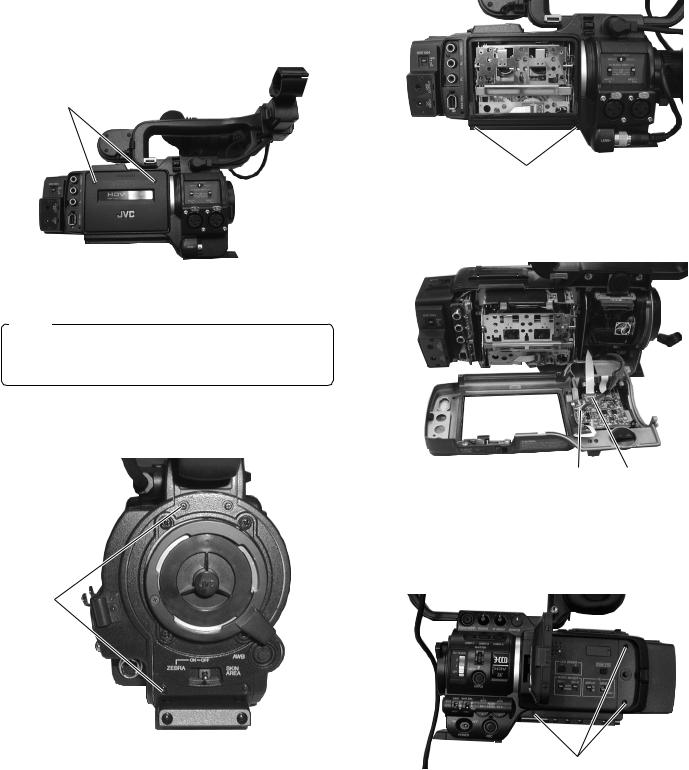
1.1HOW TO REMOVE THE COSMETIC PARTS
1.1.1 Left side cover
(1)Remove the two screws 1, slide the cassette cover downward and pull out to remove.
1
Fig. 1.1.1 (1)
Note :
When attaching the cassette cover, make sure to insert the hook of the cassette cover to the correct position of the cassette housing.
(2) Remove the two screws 2 .
2
(3) Remove the two screws 3 and open the left side cover.
3
Fig. 1.1.1 (3)
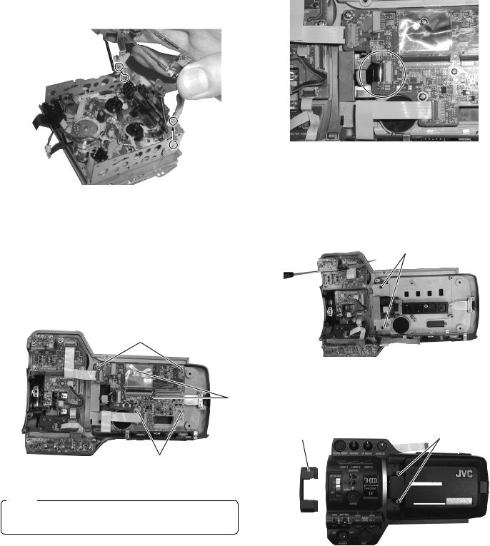
(4) Disconnect the cables CN13 and CN43.
CN43 CN13
Fig. 1.1.1 (4)
1.1.2 Right side cover
(1) Remove the five screws 4 and open the right side cover.
Fig. 1.1.1 (2)
4
Fig. 1.1.2 (1)
1-1
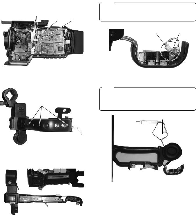
1.2 HOW TO REMOVE THE OPTICAL BLOCK ASSEMBLY
CAUTION
When removing/mounting the optical block assembly in the camera, take care not to damage cables, also the positioning of the wire assembly is important. A malfunction may occur if a wire is somehow caught up.
4(1) Remove left side cover and the right side cover. (see section 1.1.1 and 1.1.2)
(2)Remove the two screws 1 and remove the FAN motor.
1
Fig. 1.1.2 (2)
(2)Disconnect the cables CN14, CN24 and CN43 on AUDIO board, CN10 and CN52 on STA board, CN52 on SWP board.
Fig. 1.2 (1)
(3) Remove the two screws 2 and remove the SD board.
(4) Disconnect the cables CN26, CN27 and CN28.
2 CN26 CN27
CN52 CN10 CN43 CN24 CN14
CN28
Fig. 1.1.2 (3) |
Fig. 1.2 (2) |
1-2

(5)Remove the five screws 33 and 4, then remove the optical block assembly carefully not to damage boards and cables.
3
4
Fig. 1.2 (3)
Fig. 1.2 (4)
Note :
•The CCDs are bonded precisely to the prism. In case of trouble with a CCD, it is not possible to replace an individual CCD, but the entire optical block assembly should be replaced.
•The optical block assembly supplied as a service part.
•When replacing the optical block, attach the original FAN and FNC board to the new optical block because those are not included on the optical block assembly.
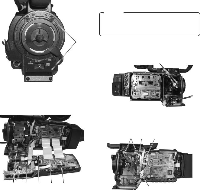
1.3HOW TO REMOVE VCR UNIT
1.3.1 Mechanism unit
(1)Remove the left side cover. (see section 1.1.1)
(2)Remove the four screws 1.
11
Fig. 1.3.1(1)
(3)Lift up the mechanism unit gently and disconnect the cablesCN75, CN16 and CN17.
CN75 CN16 CN17
Fig. 1.3.1(2)
1-3

1.3.2 Cassette housing
(1)Remove the mechanism unit. (see section 1.3.1)
(2)Remove CN1 and release the motor wire. Release the lock sideways and remove the tape guard
(4)Slide the outer unit to rear direction and lift up slightly. Pull out to side direction to release the outer unit. Perform same manner other side.
CN1 |
Motor Wire |
Fig. 1.3.2(1) |
Fig. 1.3.2(3) |
(3)Pop up the cassette housing by sliding release lever and remove the two screws 2.
Fig. 1.3.2(4)
(5) Slide the cassette housing to the position of fig.1.3.2(5) and hold the cassette housing slightly to inside direction to release it.
2
Release Lever
Fig. 1.3.2(2)
Release Position
Fig. 1.3.2(5)
1-4
(6)Release bosses of the cassette housing from the mechanism unit.
Fig. 1.3.2(6)
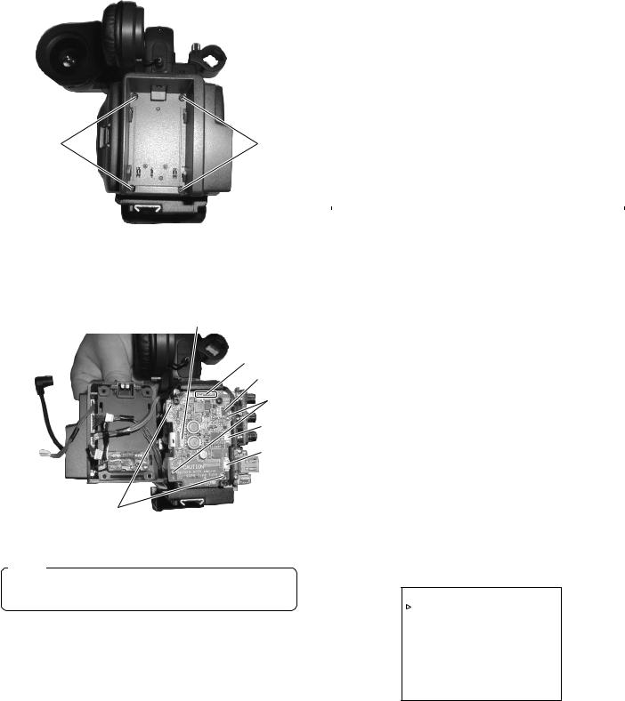
1.4HOW TO REMOVE THE MAJOR BOARDS
1.4.1 Audio board
(1)Remove right side cover. (see section 1.1.2)
(2)Disconnect cables CN44, CN45 and CN62.
(3)Remove six screws 1 and 2.
1
2
1
Fig. 1.4.1(1)
Note :
CN62 may be slightly hard to connect FPC cable. Make sure to insert the cable to correct position.
Fig. 1.4.1(2)
1.4.2 LCD monitor
(1)Remove Audio board. (see section 1.4.1)
(2)Remove two screws 3.
3
Fig. 1.4.2(1)
(3) Remove the hinge cover and remove two screws 4.
Hinge Cover |
4 |
Fig. 1.4.2(2)
1-5
1.4.3MIF board
(1)Remove the right side cover. (see section 1.1.2)
(2)Remove four screws 5.
(3)Remove the cables CN4, CN9, CN11, CN12, CN13, CN22, CN23, 34 and CN48, then lift up MIF board to release B to B connector between MIF board and MAIN board.
CN13 CN12 CN23 CN48 CN22
5
CN4
CN34
CN11
CN9
5
Fig. 1.4.3
1.4.4 MAIN board
(1)Remove MIF board. (see section 1.4.3)
(2)Remove six screws 6 and 7.
(3)Remove the cables CN3, CN16, CN17, CN18, CN19, CN26, CN27, CN28, CN29 and CN30.
76
CN29
CN26 
CN27
CN28
CN30
CN19
CN18 CN17 CN3 CN16
Fig. 1.4.4(1)
(4)Slide the MAIN board downward and pull out. Do not bend the Heat Pipe.
Do not bend the Heat Pipe.
Fig. 1.4.4(2)
(5)Remove the two screws 8. Remove the heat sink carefully because it is being fitted sticky.
8
Fig. 1.4.4(3)
1.4.5 HANDLE assembly
(1)Remove left side cover and right side cover. (see section 1.1.1 and 1.1.2)
(2)Remove two screws 9.
9
Fig. 1.4.5(1)
1-6
(3)Remove the cables CN12 and CN48. Remove the two screws 0 and lift up the handle assembly.
0
CN12 CN48
Fig. 1.4.5(2)
(4) Remove three screws !.
!
Fig. 1.4.5(3)
(5) Remove the handle cover R and handle cover T.
Fig. 1.4.5(4)
Note :
When connecting the LED connector on EAR board, ensure the polarity that the red wire should be connected longer pin of LED.
Red wire |
Longer Pin |
Fig. 1.4.5(5)
Note :
When removing the Heat Sink Ass’y, bend the Heat Pipe slightly like Fig. 1.4.5(6).
Return the bend after attaching the Heat Sink Ass’y. Do not bend the other portion of Heat Pipe.
|
About |
Do not bend |
20 degrees |
|
Fig. 1.4.5(6)
1-7
1.4.6 PS board
(1) Remove the four screws @.
@ |
@ |
Fig. 1.4.6(1)
(2)Remove the four screws # and $. Disconnect the cables CN1, 29, CN30, CN53 and CN75.
CN30
CN29
CN75
$
CN1
CN53
#
Fig. 1.4.6(2)
Note :
When replacing the fuse F1, ensure to replace with same type fuse. (refer to the parts list)
1.5SERVICE MENUS
1.5.1 Modes required in servicing
(1)While holding down the specified button(s) (FOCUS ASSIST, USER 3), press and hold the STATUS button for more than 1 second in order to display the first-level menu of the service menu hierarchy. The items in the first-level menu vary according to which specified button is being held at the moment the STATUS button is pressed. (Characters are displayed on LCD monitor screen or View finder.)
|
|
When power up |
||
|
|
|
Holding |
Holding |
|
|
DISPLAY |
DISPLAY |
|
Item |
Displayed Content |
|
button |
button |
|
|
Activation Method |
||
|
|
FOCUS |
|
FOCUS ASSIST |
|
|
USER 3 |
+ |
|
|
|
ASSIST |
|
USER 3 |
|
|
|
|
|
|
|
|
|
|
CAMERA1 MENU |
Camera setting, blemish detect |
|
|
|
CAMERA2 MENU |
Error correct ON/OFF |
|
|
|
CAMERA3 MENU |
AW data reset menu |
|
|
|
VTR1 MENU |
Repeat, FF/REW speed setting |
|
|
|
VTR2 MENU |
Long pause, shutdown setting |
|
|
|
VTR3 MENU |
Reserved, BATT, Info. |
|
|
|
DIP SW |
DIP SW MENU |
|
|
|
HOUR METER |
Hour Meter indication |
|
|
|
ERROR HISTORY |
Error History |
|
|
|
|
|
|
|
|
OTHERS |
MENU SAVE etc. |
|
|
|
|
|
|
|
|
VERSION |
CPU Version indication |
|
|
|
|
|
|
|
|
Table 1-5-1 Service Menu First Tier List
1.5.2 Operation in the first-level of the service menu
(1)While holding down the specified button(s) (FOCUS ASSIST or USER 3), press and hold the STATUS button for more than 1 second.
(2)The first-level of the service menu is displayed.
(3)Rotate the SHUTTER dial to move the cursor ( 3) on to the item to be modified.
(4)Push into the SHUTTER dial to direct the item on which the cursor ( 3) is located.
•Pressing the STATUS button returns to the MENU display.
•Can not open the service MENU while recording.
– – – A D V A N C E D M E N U – – –
V E R S I O N C H E C K . . C A M E R A 1 . .
V T R 1 . . E X I T
Fig. 1-5-2 (1)
While holding down the FOCUS ASSIST button, press and hold STATUS button for more than 1 second,this MENU screen is shown on the monitor. (Refer to Fig. 1-5-2(1))
1-8

– – – S E R V I C E M E N U – – – |
|
C A M E R A 1 . . |
|
C A M E R A 2 . . |
|
V T R 1 . . |
|
V T R 2 . . |
|
D I P |
S W . . |
H O U R |
M E T E R |
E R R O R H I S T O R Y . . |
|
O T H E R S . . |
|
E X I T |
|
Fig. 1-5-2 (2)
At first, while holding down the DISPLAY button, turn ON the power switch, and then, while holding down the USER 3 button, press and hold STATUS button for more than 1 second, this MENU screen is shown on the monitor. (Refer to Fig. 1-5-2(2))
– – – F A C T O R Y M E N U – – – |
|
C A M E R A 1 . . |
|
C A M E R A 2 . . |
|
C A M E R A 3 . . |
|
V T R 1 . . |
|
V T R 2 . . |
|
V T R 3 . . |
|
D I P |
S W . . |
H O U R |
M E T E R |
E R R O R H I S T O R Y . . |
|
O T H E R S . . |
|
E X I T |
|
|
|
Fig. 1-5-2 (3)
At first, while holding down the DISPLAY button, turn ON the power switch, and then, While holding down the FOCUS ASSIST and USER 3 button, press and hold STATUS button for more than 1 second, this MENU screen is shown on the monitor. (Refer to Fig. 1-5-2(3))
1.5.3 CAMERA 1 menu
(1)In a service menu, place the cursor ( 3) on “CAMERA 1” and push the SHUTTER dial to display the CAMERA1 menu.
– – – C A M E R A 1 – – – |
|
L C D L / R R E V E R S E O F F |
|
F A S A U D I O |
A U T O |
A L C MO D E |
A L C + E E I |
E E I M A X |
1 / 2 4 0 |
I R I S E N F A U T O |
O N |
P I X E L C OM P E N D E T C A N C E L
P A G E B A C K
Fig. 1-5-3 (1)
(2)Rotate the SHUTTER dial to move the cursor ( 3) on the mode to be adjusted.
(3)Push the SHUTTER dial so that the parameter blinks.
(4)Rotate the SHUTTER dial to vary the parameter.
(5)After completing the parameter setting, push the SHUTTER dial to stop the blinking of the parameter and store the setting in memory.
(6)After completing the setting, move the cursor ( 3) to “PAGE BACK” and push the SHUTTER dial to return to the display at the higher hierarchy level.
Item |
|
|
|
|
|
|
|
|
Parameter |
|
LCD L/R |
|
|
|
|
|
When the face of LCD screen is |
||||
|
OFF |
|
|
|
||||||
REVERSE |
|
|
|
|
|
turned toward the camera subject, |
||||
|
|
|
|
|
|
does not invert the left and right of |
||||
|
|
|
|
|
|
the LCD display. (normal image) |
||||
|
|
ON |
When the face of LCD screen is |
|||||||
|
|
|
|
|
|
turned |
|
toward the camera subject, |
||
|
|
|
|
|
|
inverts the left and right of the LCD |
||||
|
|
|
|
|
|
display. (mirror image) |
||||
|
|
|
|
|
|
|
|
|
|
|
|
|
|
|
|
|
When selected FAS mode, audio |
||||
FAS |
|
AUTO |
|
|
||||||
AUDIO |
|
|
|
|
|
recording Level will be |
||||
|
|
|
|
|
|
automatically set to AUTO mode. |
||||
|
|
SW SET |
When selected FAS mode, audio |
|||||||
|
|
|
|
|
|
recording level will be depending |
||||
|
|
|
|
|
|
on switch setting. |
||||
|
|
|
|
|
|
|
|
|
|
|
ALC MODE |
|
ALC + EEI |
|
|
When selected ALC mode |
|||||
|
|
|
|
|
|
|
including FAS mode, EEI function |
|||
|
|
|
|
|
|
|
will be activated. |
|||
|
|
ONLY ALC |
|
When selected ALC mode |
||||||
|
|
|
|
|
|
|
including FAS mode, EEI function |
|||
|
|
|
|
|
|
|
will not be activated. |
|||
|
|
|
|
|
|
|
|
|
|
|
EEI MAX |
|
U MODEL |
|
1/240 Maximum shutter speed is |
||||||
|
|
|
|
|
|
|
|
|
|
set to 1/240 second. |
|
|
|
|
|
|
|
|
|
||
|
|
|
|
|
|
|
1/480 |
Maximum shutter speed is |
||
|
|
|
|
|
|
|
|
|
|
set to 1/480 second. |
|
|
|
|
|
|
|
1/960 Maximum shutter speed is |
|||
|
|
|
|
|
|
|
|
|
|
set to 1/960 second. |
|
|
E MODEL |
|
1/200 Maximum shutter speed is |
||||||
|
|
|
|
|
|
|
|
|
|
set to 1/200 second. |
|
|
|
|
|
|
|
|
Maximum shutter speed is |
||
|
|
|
|
|
|
|
1/400 |
|||
|
|
|
|
|
|
|
|
|
|
set to 1/400 second. |
|
|
|
|
|
|
|
1/800 Maximum shutter speed is |
|||
|
|
|
|
|
|
|
|
|
|
set to 1/800 second. |
|
|
|
|
|
|
|
|
|
|
|
IRIS ENF. |
|
OFF |
When selected FULL AUTO mode, |
|||||||
AUTO |
|
|
|
|
|
IRIS mode will be depeng on IRIS |
||||
|
|
|
|
|
|
MODE switch of the lens. |
||||
|
|
|
|
|
|
When selected FULL AUTO mode, |
||||
|
|
ON |
|
|
|
|||||
|
|
|
|
|
|
Auto Iris mode will be activated |
||||
|
|
|
|
|
|
even Manual Iris mode is selected. |
||||
|
|
|
|
|
|
|
|
|
|
|
|
|
|
|
|
|
Does not execute blemish |
||||
PIXEL |
|
CANCEL |
||||||||
COMPEN DET |
|
|
|
|
|
detection. |
||||
|
|
EXECUTE Execute blemish detection. |
||||||||
|
|
|
|
|
|
|
|
|
|
|
|
|
|
|
|
|
( |
|
|
indicates the factory setting.) |
|
|
|
|
|
|
|
|
|
|||
Table 1-5-3 (1)
White blemish detection
Open the User MENU, select "VIDEO FORMAT", "REC", set to "HDV-HD24P" and push the SHUTTER dial.
Select "FRAME RATE", set to "24" and push the SHUTTER dial. Select "EXECUTE", push the SHUTTER dial, then GYHD100 is automatically rebooted.
– – – V I D E O F O RM A T – – –
F R A M E R A T E |
2 4 |
|
|
|
E X E C U T E |
R E C |
|
H D V - H D 2 4 P |
|
|
E X E C U T E |
A S P E C T |
- - - - |
|
P B O U T P U T |
7 2 0 P |
|
P B T A P E |
D V C A M |
|
O U T P U T T E RM I N A L C OM P O S I T E |
||
S E T |
U P |
0 . 0 % |
P A G E |
B A C K |
|
Fig. 1-5-3 (2)
1-9
Open the Service MENU, select "CAMERA1", "PIXEL COMPEN DET", "EXECUTE" and push the SHUTTER dial, then CCD white blemish detect operation start automatically.
At this time, the lens is closed and the camera is in the SLOW SHUTTER
mode.
– – – C A M E R A 1 – – – |
|
L C D L / R R E V E R S E O F F |
|
F A S A U D I O |
A U T O |
A L C MO D E |
A L C + E E I |
E E I M A X |
1 / 2 4 0 |
I R I S E N F A U T O |
O N |
P I X E L C OM P E N D E T E X E C U I T
P A G E B A C K
Fig. 1-5-3 (3)
After completing white blemish detection, return "REC" and "FRAME RATE" setting to original one's.
When the white blemish detection completes, the result data is stored in the memory of CPU,
end message is shown as below, then please turn off.
P I X E L C OM P E N
|
E N D |
T U R N |
P OWE R O F F |
A N D |
O N A G A I N |
Fig. 1-5-3 (4)
If any errors occurs during the detection operation, an error message is displayed , and return to MENU display.
Message |
Error details |
Treatment |
LENS NOT |
The lens does not |
No result is stored in |
CLOSED? |
close for detection. |
the EEPROM. |
|
|
|
COUNT OVER |
The number exceeds |
Only the specified |
|
the specified count. |
count of data is |
|
|
stored in the |
|
|
EEPROM. |
|
|
|
Table 1-5-3 (2)
Details on correctable white blemish
Up to 127 errors with composite video levels of 50mV or more can be corrected. No limitation of errors per line within 127 however, the maximum consecutive errors are 4 and the correction results may be inferior to the case of single error correction.
Oblique noise may be observed on the screen during white blemish detection. This is due to the principles of error correction and is not a malfunction.
White blemish can be detected in the following area.
100%
100%
Fig. 1-5-3 (5)
1.5.4 CAMERA 2 menu
(1) In a service menu, place the cursor on “CAMERA 2” and push the SHUTTER dial to display the CAMERA2 menu.
|
– – – C A M E R A 2 – – – |
|
P I X E L C OM P E N |
O N |
|
T E S T |
S I G N A L |
O F F |
P A G E |
B A C K |
|
Fig. 1-5-4
Operation ways are almost same as CAMERA 1 MENU, so please refer it.
Item |
|
|
|
|
Parameter |
|
PIXEL |
OFF |
Does not correct the detected white |
||||
COMPEN *1 |
|
|
blemish. |
|
|
|
|
|
|
Corrects the detected white blemish. |
|||
|
ON |
|
||||
|
CHECK Light up the pixels which are the |
|||||
|
|
|
detected white blemish. |
|||
|
|
|
|
|
|
|
|
|
|
( |
|
|
indicates the factory setting.) |
|
|
|
|
|
||
Table 1-5-4
*1: This mode is automatically set to ON when the power is turned on.
The OFF mode is enabled only after it is set to OFF at this screen until the power is turned off.
1-10

1.5.5 CAMERA 3 menu
In a service menu, place the cursor on “CAMERA 3” and push the SHUTTER dial to display the CAMERA3 menu.
– – – C A M E R A 3 – – –
A W / S K I N R E S E T |
C A N C E L |
|
P I X E L C OM P R E S E T C A N C E L |
||
C C D |
A D J R E S E T |
C A N C E L |
C A N |
E E P R OM R E S E T C A N C E L |
|
P A G E B A C K
Fig. 1-5-5
Operation ways are almost same as CAMERA 1 MENU, so please refer it.
Item |
|
|
|
|
Parameter |
|
AW/SKIN RESET |
|
|
|
Does not reset the auto white |
||
|
CANCEL |
|
||||
|
|
|
|
data and the skin detect data. |
||
|
|
EXECUTE |
Resets the auto white data and |
|||
|
|
|
|
the skin detect data. |
||
PIXEL COMP |
|
|
|
Does not reset the detected white |
||
|
CANCEL |
|
||||
RESET |
|
|
|
blemish data. |
||
|
|
EXECUTE |
Resets the detected white |
|||
|
|
|
|
blemish data. |
||
|
|
|
|
|
||
CCD ADJ |
|
|
|
Does not reset the CCD |
||
|
CANCEL |
|
||||
RESET |
|
|
|
adjustment data. |
||
|
|
EXECUTE |
Resets the CCD adjustment data. |
|||
CAM EEPROM |
|
|
|
Does not reset the EEPROM data |
||
|
CANCEL |
|
||||
RESET |
|
|
|
for CAMERA CPU. |
||
|
|
EXECUTE |
Resets the EEPROM data for |
|||
|
|
|
|
CAMERA CPU. |
||
|
|
|
|
|
|
|
|
|
|
|
( |
|
indicates the factory setting.) |
|
|
|
|
|
||
Table 1-5-5
1.5.6 VTR 1 menu
In a service menu, place the cursor on “VTR 1” and push the SHUTTER dial to display the VTR 1 menu.
– – – V T R 1 |
– – – |
B A T T . D I S P L A Y |
A U T O |
R E C R E P E A T |
O F F |
P L A Y R E P E A T |
O F F |
R E MO T E F F / R E W |
F F / R EW |
S T E P S L OW [ D V ] |
F R A M E |
F F / R E W S P E E D |
M A X |
V I D E O O U T H B L A N K D V
P A G E B A C K
Fig. 1-5-6
Operation ways are almost same as CAMERA 1 MENU, so please refer it.
Item |
|
|
|
|
|
|
|
|
|
Parameter |
|
BATT. |
|
OFF |
Does not indicate the Battery |
||||||||
DISPLAY |
|
|
|
|
information. |
||||||
|
|
|
|
|
Show the Battery information as |
||||||
|
|
AUTO |
|||||||||
|
|
|
|
|
Battery Info of VTR3 MENU. |
||||||
REC REPEAT |
|
|
|
|
Disable repeat recording |
||||||
|
OFF |
|
|
||||||||
|
2 |
|
|
Perform repeat recording 2 times. |
|||||||
|
5 |
|
|
Perform repeat recording 5 times. |
|||||||
|
12 |
|
|
Perform repeat recording 12 times. |
|||||||
|
|
ON |
Enable full repeat recording. |
||||||||
|
|
|
|
|
|
|
|
|
|
|
|
PLAY REPEAT |
|
|
|
Disable repeat playback. |
|||||||
|
OFF |
|
|
||||||||
|
|
ON |
Enable repeat playback. |
||||||||
|
|
|
|
|
|
|
|
|
|
|
|
REMOTE |
|
|
|
|
When FF/REW command is |
||||||
|
FF/REW |
|
|||||||||
FF/REW |
|
|
|
|
received from REMOTE, it runs as |
||||||
|
|
|
|
|
FF/REW mode. |
||||||
|
|
SEARCH |
When FF/REW command is |
||||||||
|
|
|
|
|
received from REMOTE, it runs as |
||||||
|
|
|
|
|
search FWD/REV mode. |
||||||
|
|
|
|
|
|
|
|
|
|
|
|
STEP |
FIELD |
|
|
|
|
|
|
|
|||
SLOW [DV] |
|
|
|
|
|
|
|
||||
|
FRAME |
|
|
|
|
|
|
||||
|
|
|
|
|
|
|
|
|
|
|
|
FF/REW |
|
X5 |
Maximum FF/REW speed is limited up |
||||||||
SPEED |
|
|
|
|
to x5. |
|
|
||||
|
|
X7.5 |
Maximum FF/REW speed is limited up |
||||||||
|
|
|
|
|
to x7.5. |
||||||
|
|
X10 |
Maximum FF/REW speed is limited up |
||||||||
|
|
|
|
|
to x10. |
||||||
|
|
|
*1No limitation |
||||||||
|
|
MAX |
|||||||||
|
|
|
|
|
|
|
|
|
|
|
|
VIDEO OUT |
|
DV |
Horizontal effective pixels are 720. |
||||||||
HBLANK |
|
|
|
|
|
|
|
|
|
|
|
|
STANDARD |
|
Horizontal effective pixels are |
||||||||
|
|
|
|||||||||
|
|
|
|
|
710 at 60/30 frame rate and 702 at |
||||||
|
|
|
|
|
50/25 frame rate. |
||||||
|
|
|
|
|
|
|
|
|
|
|
|
|
|
|
|
|
|
|
|
( |
|
indicates the factory setting.) |
|
|
|
|
|
|
|
|
|
|
|||
Table 1-5-6
*1: Maximum speed is x20 at VTR mode, but no function at CAM mode.
1-11

1.5.7 VTR 2 menu
In a service menu, place the cursor on “VTR 2” and push the SHUTTER dial to display the VTR 2 menu.
|
– – – |
V T R 2 |
– – – |
L O N G P A U S E |
|
O N |
|
B A T T . |
S H U T |
D OWN |
6 . 0 V |
B A T Y . A L A RM |
|
6 . 9 V |
|
A N T O N |
S H U T |
D OWN |
1 2 . 6 V |
A N T O N |
A L A RM |
1 3 . 5 V |
|
D F M A S K [ D V ] |
O F F |
||
P A G E |
B A C K |
|
|
1.5.8 VTR 3 menu
In a service menu, place the cursor on “VTR 3” and push the SHUTTER dial to display the VTR 3 menu.
– – – V T R 3 |
– – – |
|
R E S E R V D |
|
0 |
B A T T E L Y |
I N F O . . |
|
P A G B A C K
Fig. 1-5-7
Operation ways are almost same as CAMERA 1 MENU, so please refer it.
Item |
|
|
|
|
|
|
|
Parameter |
|
LONG PAUSE |
|
OFF |
Disable the long pause function. |
||||||
|
|
|
|
|
|
Enable the long pause function. |
|||
|
|
ON |
|
|
|
||||
|
|
|
|
|
|
|
|
|
|
|
|
|
|
|
Setting of the battery voltage when |
||||
BATT. |
|
6.8V |
|
||||||
SHUTDOWN *1 |
|
|
|
|
|
shutdown should occur. (Setting in |
|||
|
|
|
|
|
0.1V steps between 6.3V and 7.5V.) |
||||
|
|
|
|
|
|
||||
|
|
|
|
|
|
|
|
|
|
|
|
|
|
|
Setting of the battery voltage when |
||||
BATT. |
|
6.9V |
|
||||||
ALARM *1 |
|
|
|
|
|
battery alarm is indicated. (Setting in |
|||
|
|
|
|
|
|
0.1 V steps between 6.3V and 8.0V.) |
|||
|
|
|
|
|
|
|
|
|
|
ANTON SHUT |
|
|
|
Setting of the ANTON battery voltage |
|||||
|
12.0V |
||||||||
DOWN |
|
|
|
|
|
when shutdown should occur. (Setting |
|||
|
|
|
|
|
|
in 0.1V steps between 10.5V and |
|||
|
|
|
|
|
|
13.6V.) |
|
|
|
|
|
|
|
|
|
|
|
|
|
ANTON |
|
|
|
Setting of the ANTON battery voltage |
|||||
|
13.5V |
||||||||
ALARM |
|
|
|
|
|
when battery alarm is indicated. |
|||
|
|
|
|
|
|
(Setting in 0.1 V steps between 10.5V |
|||
|
|
|
|
|
|
and 13.6V.) |
|||
DV DF MASK *2 |
|
|
|
"1" is recorded as per format. |
|||||
|
OFF |
|
|
||||||
|
|
ON |
"0" is always recorded. |
||||||
|
|
|
|
|
|
|
|
|
|
|
|
|
|
|
|
( |
|
|
indicates the factory setting.) |
|
|
|
|
|
|
|
|
||
Table 1-5-7
*1 : When operating by DC input, then “SHUT DOWN” will be set to 6.0V, and “ALARM” will be set to 6.9V automatically, and these setting will not relate to menu setting.
*2 : FRAME RATE 50/25 only
Fig. 1-5-8 (1)
Changing of setting is prohibited.
Item |
|
|
Parameter |
|
RESERVED |
0 |
Normal setting |
||
|
|
|
|
|
BATTERY INFO |
|
Refer to next page. |
||
|
|
|
|
|
|
|
( |
|
indicates the factory setting.) |
|
|
|
||
Table 1-5-8 (1)
BATTERY INFO Display
Display method
Move the cursor to the “BATTERY INFO..” in “VTR3” screen and press SHUTTER dial. BATTERY INFO screen (right figure) will be displayed.
– – – B A T T E R Y I N F O – – –
T Y P E |
A N T O N S M A R T |
|
R E M A I N |
1 2 5 M i n / 9 5 % |
|
< 1 2 . 8 V 1 . 2 5 A |
3 0 ° C > |
|
F U L L C A P A C I T Y |
3 2 . 6 A h |
|
P R E S E N T C A P A C I T Y 3 0 . 5 A h
S E R I A L N O . |
5 5 5 2 0 |
M A N U F A C T U R E |
2 0 0 4 / 0 4 |
S O F T WA R E R E V . |
1 2 . 5 |
C A L I B R A T I O N R E Q U I R E D O F F
P A G E B A C K
Fig.1-5-8 (2) BATTERY INFO
(When the Anton/Bauer Smart Battery is detected)
1-12

Item |
|
|
Descriptions |
|
|
|
|
|
|
TYPE |
|
ANTON SMART |
When ANTON/BAUER SMART BATTERY is connected |
|
|
|
|
AFG |
When BATTERY with I/F of AFG (AnalogFuelGauge) is connected |
|
|
|
OTHERS |
When other BATTERY is connected |
|
|
|
NO DETECT |
When no BATTERY is connected |
REMAIN |
|
Minute |
Remaining battery lasting time [min] calculated based on current power consumption |
|
|
|
% |
Current remaining capacity [%] corresponding to total battery capacity |
|
|
|
Voltage |
Output voltage of battery |
|
|
|
|
|
|
|
|
Current |
Output current of battery |
|
|
|
|
|
|
|
|
Temperature |
Temperature of battery |
|
FULL CAPACITY |
|
Capacity [Ah] when the BATTERY is fully charged |
||
PRESENT CAPACITY |
Current BATTERY capacity [Ah] |
|||
SERIAL NO. |
|
Manufactured serial number |
||
|
|
|
|
|
MANUFACTURE |
|
Manufactured date |
|
|
|
|
|
||
SOFTWARE REV. |
|
Software revision number |
||
CALIBRATION |
|
OFF Calibration not required |
||
REQUIRED |
|
ON Calibration required |
||
|
|
|
|
|
Table 1-5-8 (2)
1.5.9 DIP SW menu
(1) In a service menu, place the cursor on “DIP SW ” and push the SHUTTER dial to display the DIP SW menu.
– – – |
D I P S W [ 1 / 6 ] – – – |
|
D I P S W A L L R E S E T |
C A N C E L |
|
N E X T |
P A G E |
|
P A G E |
B A C K |
|
– – – D I P S W [ 2 / 6 ] – – –
D I P S W |
0 |
0 |
D I P S W |
1 |
O F F |
D I P S W |
2 |
O F F |
D I P S W |
3 |
O F F |
D I P S W |
4 |
O F F |
D I P S W |
5 |
O F F |
D I P S W |
6 |
O F F |
D I P S W |
7 |
O F F |
N E X T |
P A G E |
|
P A G E |
B A C K |
|
– – – |
D I P |
D I P S W |
8 |
D I P S W |
9 |
D I P S W |
1 0 |
D I P S W |
1 1 |
D I P S W |
1 2 |
D I P S W |
1 3 |
D I P S W |
1 4 |
D I P S W |
1 5 |
N E X T |
P A G E |
P A G E |
B A C K |
S W [ 3 / 6 ] – – –
O F F
O F F
O F F
O F F
O F F
O F F
O F F
O F F
Fig. 1-5-9 (1)
– – – |
D I P |
D I P S W |
1 6 |
D I P S W |
1 7 |
D I P S W |
1 8 |
D I P S W |
1 9 |
D I P S W |
2 0 |
D I P S W |
2 1 |
D I P S W |
2 2 |
D I P S W |
2 3 |
N E X T |
P A G E |
P A G E |
B A C K |
S W [ 4 / 6 ] – – –
O F F
O F F
O F F
O F F
O F F
O F F
O F F
O F F
Fig. 1-5-9 (2)
– – – |
D I P |
D I P S W |
2 4 |
D I P S W |
2 5 |
D I P S W |
2 6 |
D I P S W |
2 7 |
D I P S W |
2 8 |
D I P S W |
2 9 |
D I P S W |
3 0 |
D I P S W |
3 1 |
N E X T |
P A G E |
P A G E |
B A C K |
S W [ 5 / 6 ] – – –
O F F
O F F
O F F
O F F
O F F
O F F
O F F
O F F
Fig. 1-5-9 (3)
– – – D I P S W [ 6 / 6 ] – – –
D I P S W |
3 2 |
0 |
D I P S W |
3 3 |
0 |
D I P S W |
3 4 |
0 |
D I P S W |
3 5 |
O F F |
D I P S W |
3 6 |
O F F |
D I P S W |
3 7 |
O F F |
D I P S W |
3 8 |
O F F |
D I P S W |
3 9 |
O F F |
P A G E |
B A C K |
|
Fig. 1-5-9 (4) |
Fig. 1-5-9 (5) |
Fig. 1-5-9 (6) |
1-13

Operation ways are almost same as CAMERA 1 menu, so please refer it.
All DIP Switch settings which are shown below should not be changed ecxept for repair or maintenance. And do not forget to return original position after repair.
|
Item |
Parameter |
Factory |
|
|
|
setting |
|
|
|
|
|
--- DIP SW 1/6 --- |
|
|
|
DIP SW |
CANCEL Cancel to reset all |
CANCEL |
|
ALL |
DIPSW settings. |
|
|
RESET |
EXECUTE Execute to reset all |
|
|
|
DIPSW settings. |
|
|
|
|
|
|
--- DIP SW 2/6 --- |
|
|
|
|
|
|
|
DIP SW 0 |
1 : Displays error rate monitor |
0 |
|
|
and CPU port information |
|
|
DIP SW 1 |
ON : Disable warning message |
OFF |
|
|
display |
|
|
DIP SW 2 |
Change prohibited |
OFF |
|
DIP SW 3 |
ON : Disable DEW warning |
OFF |
|
DIP SW 4 |
Change prohibited |
OFF |
|
DIP SW 5 |
Change prohibited |
OFF |
|
DIP SW 6 |
Change prohibited |
OFF |
|
DIP SW 7 |
Change prohibited |
OFF |
|
--- DIP SW 3/6 --- |
|
|
|
|
|
|
|
DIP SW 8 |
Change prohibited |
OFF |
|
DIP SW 9 |
Change prohibited |
OFF |
|
DIP SW 10 |
ON : Displays error rate solely |
OFF |
|
|
for audio block on the error rate |
|
|
|
monitor screen |
|
|
|
|
|
|
DIP SW 11 |
Change prohibited |
OFF |
|
DIP SW 12 |
Change prohibited |
OFF |
|
DIP SW 13 |
Change prohibited |
OFF |
|
|
|
|
|
DIP SW 14 |
Change prohibited |
OFF |
|
|
|
|
|
DIP SW 15 |
Change prohibited |
OFF |
|
|
|
|
|
--- DIP SW 4/6 --- |
|
|
|
DIP SW 16 |
Change prohibited |
OFF |
|
DIP SW 17 |
Change prohibited |
OFF |
|
DIP SW 18 |
Change prohibited |
OFF |
|
|
|
|
|
DIP SW 19 |
Change prohibited |
OFF |
|
DIP SW 20 |
Change prohibited |
OFF |
|
|
|
|
|
DIP SW 21 |
Change prohibited |
OFF |
|
|
|
|
|
DIP SW 22 |
Change prohibited |
OFF |
|
|
|
|
|
DIP SW 23 |
Change prohibited |
OFF |
|
|
|
|
|
--- DIP SW 5/6 --- |
|
|
|
|
|
|
|
DIP SW 24 |
Change prohibited |
OFF |
|
DIP SW 25 |
Change prohibited |
OFF |
|
DIP SW 26 |
Change prohibited |
OFF |
|
DIP SW 27 |
Change prohibited |
OFF |
|
DIP SW 28 |
Change prohibited |
OFF |
|
DIP SW 29 |
Change prohibited |
OFF |
|
DIP SW 30 |
Change prohibited |
OFF |
|
DIP SW 31 |
Change prohibited |
OFF |
|
|
|
|
1-14
--- DIP SW 6/6 |
--- |
|
DIP SW 32 |
Change prohibited |
0 |
DIP SW 33 |
Change prohibited |
0 |
DIP SW 34 |
Change prohibited |
0 |
DIP SW 35 |
Change prohibited |
OFF |
DIP SW 36 |
Change prohibited |
OFF |
DIP SW 37 |
Change prohibited |
OFF |
DIP SW 38 |
Change prohibited |
OFF |
DIP SW 39 |
Change prohibited |
OFF |
Table 1-5-9
ERROR RATE MONITOR screen
By setting "DIP SW 0" to "1", error rate and each CPU port information display screen will appear on the LCD monitor, View finder and monitor.
The values which are pointed by arrow are the error rate value. Error rate of CH-1 shown in upper row, and CH-2 shown in lower row, and these value are indicated total AUDIO/VIDEO error rate.
When the error rate increase , the warning message "HEAD CLEANING REQUIRED" is displayed. And this message is indicate when the error rate value is over 4,500 (one-channel AUDIO/VIDEO total) for 7 seconds consecutively.
ERROR RATE indicator
|
|
|
|
|
|
|
|
|
|
|
|
|
|
|
|
|
|
|
|
|
|
|
|
|
|
|
|
|
|
|
0 0 : 0 0 : |
0 0 : |
0 0 |
||||||
|
|
XXXX |
|
XX |
|
XX |
|
XX |
|
|
SP 2 |
0 mir |
|||||||
|
|
|
|
|
|
|
|
|
|
|
|
|
|
|
|
|
|
A D P |
|
|
|
|
|
|
|
|
|
|
|
|
|
|
|
|
|
|
|
F A S |
|
|
|
|
|
|
|
|
|
|
|
|
|
|
|
|
|
|
|
-3 d B |
|
|
|
|
|
|
|
|
|
|
|
|
|
|
|
|
|
|
XX |
F A W |
|
65535 |
|
XX |
|
XX |
|
XX |
|
XX |
|
XX |
|
XX |
|
I |
|||||
65535 |
|
XX |
|
XX |
|
XX |
|
XX |
|
XX |
|
XX |
|
SD |
|||||
F I L 1 |
T |
XX |
|
XX |
|
|
|
|
XX |
|
|
|
XXXX |
|
B |
||||
F 5. 6 8 |
D |
XX |
|
|
CH 1 |
-- |
-- |
-+ |
-- |
|
|
|
|
|
1 2 |
. |
2 V |
||
|
|
CH 2 |
-- |
-- |
-+ |
-- |
|
|
|
|
|
||||||||
S T B Y |
|
|
0 1 / 0 2 / |
0 3 AM0 1 : |
2 3 |
: |
4 5 |
||||||||||||
Fig. 1-5-9 (7)

1.5.10HOUR METER
In a service menu, place the cursor on “HOUR METER ” and push the SHUTTER dial to display the HOUR METER menu.
– – – H O U R M E T E R [ 1 / 2 ] – – –
D R UM |
|
C L E A R |
T O T A L D R UM |
0 0 0 0 0 0 H |
|
F A N |
|
0 0 0 0 0 0 H |
P O W E R |
|
0 0 0 0 0 0 H |
C A P S T A N |
0 0 0 0 0 0 H |
|
S E A C H |
|
0 0 0 H 0 0 M |
F F / R E W |
0 0 0 H 0 0 M |
|
N E X T |
P A G E |
|
P A G E |
B A C K |
|
Fig. 1-5-10 (1)
– – – H O U R M E T E R [ 2 / 2 ] – – –
L O A D I N G |
0 0 0 0 0 0 0 |
E J E C T |
0 0 0 0 0 0 0 |
F W D / R E V |
0 0 0 0 0 0 0 |
C L E A N I N G T A P E |
0 0 0 0 0 0 0 |
P A G E B A C K |
|
Fig. 1-5-10 (2)
Operation ways are almost same as CAMERA 1 menu, so please refer it.
Item |
|
Parameter |
DRUM |
000000 |
Displays the drum hour |
|
|
meter(maintenance for drum) |
|
CLEAR |
Resets the drum hour meter. |
|
|
|
TOTAL DRUM |
000000 |
Displays the total hour meter. |
|
CLEAR |
Resets the total drum hour meter. |
|
|
(This does not work unless the special |
|
|
setting) |
|
|
|
FAN |
000000 |
Displays the fan hour meter. |
|
CLEAR |
Resets the fan hour meter. |
|
|
|
POWER |
000000 |
Displays the power hour meter. |
|
CLEAR |
Resets the power hour meter. |
|
|
|
CAPSTAN |
000000 |
Displays the capstan hour meter. |
|
CLEAR |
Resets the capstan hour meter. |
|
|
|
SEARCH |
000000 |
Displays the search hour meter. |
|
CLEAR |
Resets the search hour meter. |
|
|
|
FF/REV |
000000 |
Displays the FF/REW hour meter. |
|
CLEAR |
Resets the FF/REW hour meter. |
|
|
|
LOADING |
000000 |
Displays the loading count. |
|
CLEAR |
Resets the loading count. |
|
|
|
EJECT |
000000 |
Displays the eject count. |
|
CLEAR |
Resets the eject count. |
|
|
|
FWD/REV |
000000 |
Displays the forward/reverse |
|
|
switching count. |
|
CLEAR |
Resets the forward/reverse switching |
|
|
count. |
|
|
|
CLEANING TAPE |
000000 |
Displays the cleaning tape working |
|
|
count. |
|
CLEAR Resets the cleaning tape working |
|
|
|
count. |
|
|
|
Table 1-5-10
1.5.11ERROR HISTORY
In a service menu, place the cursor on “ERROR HISTORY ” and push the SHUTTER dial to display the ERROR HISTORY menu.
– – – E R R O R H I S T O R Y – – –
( H I S T O R Y - 1 ) |
7 1 0 1 |
C A P MO T O R F A I L U R E |
|
( H I S T O R Y - 2 ) |
7 1 0 1 |
C A P MO T O R F A I L U R E |
|
( H I S T O R Y - 3 ) |
7 1 0 1 |
C A P MO T O R F A I L U R E |
|
( H I S T O R Y - 4 ) |
7 1 0 1 |
C A P MO T O R F A I L U R E |
|
C L E A R |
C A N C E L |
P A G E B A C K |
|
Fig. 1-5-11
(1)Rotate the SHUTTER dial to move the cursor onto the item to show details.
(2)Push the SHUTTER dial so that the details of ERROR HISTORY is shown.
(3)Rotate the SHUTTER dial to move cursor onto the “CLEAR”, push the SHUTTER dial, then ERROR HISTORY will be deleted.
Note :
ERROR HISTORY was stored from “HISTORY-1” box to “HISTORY-4”box. Latest error was stored “HISTORY-4” box, and if there will be occur another error then latest error history will be rewrite on “HISTORY-4”. From “HISTORY- 1” to “HISTORY-3” will not rewrite, except to “CLEAR” operation.
1.5.12 Detail indication of ERROR HISTORY
In a ERROR HISTORY display, place a cursor onto the item and push SHUTTER dial, then detail display (MECHANISM INFO) picture will be shown.
MECHANISM INFO has 2 pages.
– – – M E C H A N I S M I N F 0 1 / 2 – –
P . T M 0 0 0 0 0 0 H
S Y S MO D E : P L A Y ( 0 1 . 0 0 )
M S D MO D E : P L A Y ( 0 1 . 0 0 )
|
– > S T O P ( 0 0 . 0 0 ) |
L A S T K E Y : P L A Y ( 0 1 . 0 0 ) |
|
T A P E R E M [ 0 0 0 0 ] |
|
D E W [ 0 0 ] |
T E M P [ 0 0 ] |
D I A M E T E R |
T U [ 0 0 ] S P [ 0 0 ] |
N E X T P A G E
P A G E B A C K
Fig. 1-5-12 (1)
– – – M E C H A N I S M I N F 0 2 / 2 – –
M . P O S I B R K 2 F A S T > B R K 2 F A S T H . P O S I I N I T > C A S S I N C A P [ O F F F W D ] R E L [ O F F F W D ] T U [ O N ] S P [ O F F ] D RM [ O F F ] D R V [ 0 0 ] C A P V [ 0 0 ] R E L V [ 0 0 ] MC V [ 0 0 ] R E L I [ 0 0 ]
B G N [ O F F ] E N D [ O N ] C A S [ O F F ] S T D [ O F F ] H W [ O F F ] H W 2 [ O F F ] S P L [ O F F ] T H I N [ O N ]
P A G E B A C K
Fig. 1-5-12 (2)
1-15
Item |
Content |
|
|
|
Displayed Content |
|
|
|
|
|
|
|
|
|
|
P.TM |
POWER HOUR METER |
|
Power hour meter is displayed. |
|
|||
SYS MODE |
SYSCON CPU mode when error occurred |
SFF/SREW parameter is speed display. |
|
||||
|
PLAY (03, 00) |
(Refer to Table 1-9-11 (2) Speed parameter) |
|||||
|
|
|
Parameters of other modes are irrelevant. |
||||
|
MODE DATA |
Parameter |
|
|
|
|
|
|
|
|
EJECT (01) |
: Eject |
|
|
|
MSD MODE |
MSD CPU mode and target mode when |
STOP (02) |
|
: Stop |
|
|
|
|
error occurred |
|
PLAY (03) |
|
: Play |
REC (13) |
: Rec |
|
PLAY (01, 00) |
STL (04) |
|
: Still |
RECP (14) |
: Rec Pause |
|
|
|
|
FF (05) |
|
: FF |
DVRC (15) |
: DV Rec |
|
MODE DATA |
Parameter |
REW (06) |
|
: Rew |
DVRP (16) : DV Rec Pause |
|
|
|
|
SFF (07) |
|
: Search Fwd |
POFF (1A) |
: Power Off |
|
|
|
SREW (08) |
: Search Rev |
NDEF (1F) |
: During initial operation |
|
|
|
|
SFF/SREW parameter is speed display (See Table 1-9-11 (2)) |
||||
|
|
|
|
||||
LAST KEY |
Final Key code when error occurred |
Other parameters are 01: ON, 00: OFF |
|
||||
|
PLAY (E7, 01) |
|
|
|
|
|
|
|
MODE DATA |
Parameter |
REC (E0) |
|
: Rec |
SFF (EB) |
: Search Fwd |
|
RECP (E1) |
: Rec Pause |
SREW (EC) : Search Rev |
||||
|
|
|
|||||
|
|
|
DVRP (E2) |
: DV Rec Pause |
STOP (F0) |
: Stop |
|
|
|
|
ADUB (E5) |
: Audio Dub |
EJECT (F1) : Eject |
||
|
|
|
ADBP (E6) |
: Audio Dub Pause |
HWUP (F2) : Housing Up |
||
|
|
|
PLAY (E7) |
|
: Play |
HWDN (F3) : Housing Down |
|
|
|
|
STL (E8) |
|
: Still |
POFF (F4) |
: Power Off |
|
|
|
FF (E9) |
|
: FF |
DVRC (F5) |
: DV Rec |
|
|
|
REW (EA) |
|
: Rew |
PON (FA) |
: Power on |
|
|
|
|
||||
TAPE REM |
TAPE REMAIN |
|
Displays tape remaining in minutes ([FFFF] : not detected) |
||||
|
|
|
|
|
|||
DEW |
DEW sensor A/D intake value |
DEW display at over [48] |
|
|
|||
|
|
|
|||||
TEMP |
Temperature sensor A/D intake value |
Temperature is displayed in hexadecimal value. |
|||||
|
The value “49” [5°C] is threshold of |
-10°C a [22] |
20°C a [7C] |
50°C a [CC] |
|
||
|
detecting low temperture. The value “DC” |
- 5°C a [2D] |
25°C a [8C] |
55°C a [D4] |
|
||
|
[60°C] is the threshold of displaying “OVER |
0°C a [3A] |
30°C a [9C] |
60°C a [DC] |
|
||
|
HEATING” message. |
|
5°C a [49] |
35°C a [AA] |
“OVER HEATING” message |
||
|
|
|
10°C a [59] |
40°C a [B7] |
65°C a [E1] |
|
|
|
|
|
15°C a [6A] |
45°C a [C2] |
70°C a [E6] |
|
|
|
|
|
|||||
DIAMETER |
Displays wound tape diameter (Take-up, Supply) |
[00]—[FF] : 0mm-82mm (Diameter) ([00] is non-detected) |
|||||
|
|
|
|||||
M. POSI |
Mechanism position and target mechanism |
[2EJ], [EJ], [EJ2CAIN], [CAIN], [CAIN2HLD], [HLD], |
|||||
|
position |
|
[HLD2REV], [REV], [REV2FWD], [FWD], [FWD2STP], [STP], |
||||
|
|
|
[STP2], [CLNOFF], [INIT] |
|
|
||
|
|
|
|
|
|
||
CAP |
Capstan status |
|
[ON] |
: Rotate |
[FWD/REV]: Direction display |
||
|
|
|
[OFF] |
: Stop |
|
|
|
|
|
|
|
|
|
||
REL |
Reel status |
|
[ON] |
: Rotate |
[FWD/REV]: Direction display |
||
|
|
|
[OFF] |
: Stop |
|
|
|
|
|
|
|
|
|
|
|
DRM |
Drum status |
|
[ON] |
: Rotate |
|
|
|
|
|
|
[OFF] |
: Stop |
|
|
|
|
|
|
|
||||
DIR |
Direction of tape running (Direction of target) |
[FWD/REV]: Direction display |
|
||||
|
|
|
|
|
|
||
DRV |
Drum control voltage |
|
[00-FF] : 0—3V |
|
|
||
|
|
|
|
|
|
||
CAPV |
Capstan control voltage |
|
[00-FF] : 0—3V |
|
|
||
|
|
|
|
|
|
|
|
RELV |
Reel control torque value |
|
[00-FF] |
: 0—3A |
|
|
|
|
|
|
|
|
|
|
|
1-16

Item |
|
|
Content |
|
|
|
|
Displayed Content |
|
||||||
|
|
|
|
|
|
|
|
|
|
|
|
|
|
|
|
MCV/SPD |
Loading/cassette housing control voltage |
|
[00-FF] : 0—8V |
(Displays mode motor control voltage |
|||||||||||
|
|
(when error code 4xxx and error code 3xxx |
|
|
|
|
during error code 3xxx) |
|
|||||||
|
|
is displayed.) |
|
|
|
|
(Displays cassette motor control voltage |
||||||||
|
|
|
|
|
|
|
|
|
|
|
during error code 4xxx) |
|
|||
|
|
Tape speed (When the code excepting |
|
[00-FA] : 0—25X |
(FF is displayed when the speed is faster |
||||||||||
|
|
error code 4xxx and error code 3xxx is |
|
|
|
|
than this.) |
|
|
||||||
|
|
displayed.) |
|
|
|
|
|
|
|
“Tape speed” is a function to convert the |
|||||
|
|
|
|
|
|
|
|
|
|
|
hexadecimal value into a decimal value, |
||||
|
|
|
|
|
|
|
|
|
|
|
and no speed parameter of the tape. |
||||
|
|
|
|
|
|
|
|
|
|
|
(ex. FAh = 250 → The speed is 25.0X.) |
||||
RELI |
Reel current (Cassette housing motor current |
|
[00-FF] : 0—1.2A |
|
|
|
|
|
|||||||
|
|
only during housing-related warning) |
|
|
|
|
|
|
|
|
|
||||
|
|
|
|
|
|
|
|
|
|
|
|
|
|||
BGN |
Begin sensor |
|
[ON] |
: Leader tape detected |
|
||||||||||
|
|
|
|
|
|
|
|
[OFF] |
: Magnetic tape detected |
|
|||||
|
|
|
|
|
|
|
|
|
|
|
|
|
|
|
|
END |
End sensor |
|
|
|
|
[ON] |
: Trailer tape detected |
|
|
||||||
|
|
|
|
|
|
|
|
[OFF] |
: Magnetic tape detected |
|
|||||
|
|
|
|
|
|
|
|
|
|
|
|
|
|
||
CAS |
Cassette SW status |
|
[ON] |
: No cassette |
|
|
|||||||||
|
|
|
|
|
|
|
|
[OFF] |
: Cassette detected |
|
|
||||
|
|
|
|
|
|
|
|
|
|
|
|
|
|
|
|
THIN |
Thin tape detection |
|
[ON] |
: THIN |
|
|
|
|
|
||||||
|
|
|
|
|
|
|
|
[OFF] |
: NORMAL |
|
|
|
|
|
|
|
|
|
|
|
|
|
|
|
|
|
|
|
|||
|
|
|
|
|
Table 1-5-12 (1) MECHANISM INFO content |
|
|
||||||||
|
|
|
|
|
|
|
|
|
|
|
|
|
|||
|
|
|
|
|
|
Parameter |
|
Speed |
|
|
Parameter |
Speed |
|||
|
Parameter |
|
Speed |
|
|
|
|
||||||||
|
|
|
|
|
|
|
|
|
|
|
|
|
|||
|
00 |
|
x 0 |
|
|
|
82 |
x 1.08 |
|||||||
|
|
|
|
|
|
|
|
|
|
|
|||||
|
BD |
|
|
+ 8.5 |
|
|
|
|
|
|
|||||
|
|
|
|
|
|
|
|
|
|
|
|
|
|
||
|
|
|
1F |
|
x 0.03 |
|
|
83 |
x 1.11 |
||||||
|
|
|
|
|
|
|
|
|
|
||||||
|
A9 |
|
|
+ 5.5 |
|
|
|
|
|
||||||
|
|
|
|
|
|
|
|
|
|
|
|
|
|
||
|
|
|
40 |
|
x 0.10 |
|
|
84 |
x 1.12 |
||||||
|
|
|
|
|
|
|
|
|
|
||||||
|
91 |
|
|
+ 2.5 |
|
|
|
|
|
||||||
|
|
|
|
|
53 |
|
x 0.20 |
|
|
85 |
x 1.16 |
||||
|
|
|
|
|
|
|
|
|
|
||||||
|
80 |
|
|
+ 1 |
|
|
|
|
|
||||||
|
|
|
|
|
|
|
|
|
|
|
|
|
|
||
|
|
|
61 |
|
x 0.30 |
|
|
91 |
x 2.00 |
||||||
|
81 |
|
|
– 1.5 |
|
|
|
|
|
||||||
|
|
|
|
|
|
|
|
|
|
|
|
|
|
||
|
|
|
6D |
|
x 0.50 |
|
|
A9 |
x 5.00 |
||||||
|
|
|
|
|
|
|
|
|
|
||||||
|
91 |
|
|
– 2.5 |
|
|
|
|
|
||||||
|
|
|
|
|
|
|
|
|
|
|
|
|
|
||
|
|
|
7A |
|
x 0.80 |
|
|
BD |
x 9.00 |
||||||
|
|
|
|
|
|
|
|
|
|
||||||
|
A9 |
|
|
– 4.5 |
|
|
|
|
|
||||||
|
|
|
|
|
|
|
|
|
|
|
|
|
|
||
|
|
|
7B |
|
x 0.84 |
|
|
C0 |
x 10.0 |
||||||
|
|
|
|
|
|
|
|
|
|
||||||
|
BD |
|
|
– 6.5 |
|
|
|
|
|
||||||
|
|
|
|
|
7D |
|
x 0.90 |
|
|
|
|
||||
|
|
|
|
|
|
|
|
|
|
|
|
||||
|
|
|
|
|
|
|
|
|
|
|
|
||||
|
|
|
|
|
|
|
|
|
|
|
|
||||
Table 1.5.12 (2) HDV Speed parameter |
|
7F |
|
x 0.96 |
|
|
|
|
|||||||
|
|
|
|
|
|
|
80 |
|
x 1.00 |
|
|
|
|
||
|
|
|
|
|
|
|
|
|
|
|
|
|
|
||
|
|
|
|
|
|
|
81 |
|
x 1.04 |
|
|
|
|
||
|
|
|
|
|
|
|
|
|
|
|
|
|
|
|
|
Table 1-5-12 (3) DV Speed parameter
1-17

Error code |
Display |
Content of occurrence |
Method of detection |
Detected signal |
|
|
|
|
|
0201 |
CONDENSATION ON DRUM |
DEW detected |
If DEW sensor detects |
IC71 (MSD) –detects voltage |
|
|
|
condensation |
of pin E16 |
|
|
|
|
|
3200 |
LOADING FAILURE |
Does not load |
If mechanism position does |
IC71 (MSD) –detects output |
|
|
|
not move in loading direction |
of pin F14, rotary encoder |
|
|
|
within 5 seconds |
|
|
|
|
|
|
3300 |
UNLOADING FAILURE |
Does not unload |
If mechanism position does |
IC71 (MSD) –detects output |
|
|
|
not move in unloading |
of pin F14, rotary encoder |
|
|
|
direction within 5 seconds |
|
|
|
|
|
|
|
No display |
Does not intake |
If intake is not completed |
IC71 (MSD) –pin M9, |
|
|
|
within 5 seconds (Ejects |
CASSETTE SW is not |
|
|
|
without warning) |
detected within 5 seconds |
|
|
|
|
|
4100 |
CASSETTE EJECT FAILURE |
Does not eject |
If eject is not completed |
IC71 (MSD) –pin P9, |
|
|
|
within 5 seconds |
HOUSING SW is not |
|
|
|
|
detected within 5 seconds |
|
|
|
|
|
5605 |
DEFECTIVE TAPE |
Tape abnormality |
If begin or end side sensor is |
IC71 (MSD) –pin E15, START |
|
|
during intake |
ON after intake |
sensor and pin E14, |
|
|
|
|
END sensor are both detected |
|
|
|
|
|
5606 |
DEFECTIVE TAPE |
Tape tear during |
If reel FG is excessive during |
IC71 (MSD) –pin R14, TU |
|
|
unloading |
unloading |
REEL FG is detected |
|
|
|
|
|
5607 |
DEFECTIVE TAPE |
Tape tear during |
If reel FG is insufficient during |
IC71 (MSD) –pin R14, TU |
|
|
loading |
loading |
REEL FG is detected |
|
|
|
|
|
5608 |
DEFECTIVE TAPE |
Tape tear on the |
If only supply side reel does |
IC71 (MSD) –pin R13, SUP |
|
|
loading side |
not rotate during FWD/REV |
REEL FG is not detected |
|
|
|
|
|
5609 |
DEFECTIVE TAPE |
Tape tear during |
If tape slack takeup is not |
IC71 (MSD) –pin R14, TU |
|
|
slack takeup |
completed within 10 seconds |
REEL FG and pin R13, SUP |
|
|
|
|
REEL FG are both detected |
5702 |
TAPE END DET. ERROR |
End sensor |
If trailer tape sending is not |
IC71 (MSD) –pin E14, END |
|
|
abnormality |
completed within 3 seconds |
sensor is detected for over 3 |
|
|
|
|
seconds |
|
|
|
|
|
5802 |
TAPE BEGIN DET. ERROR |
Begin sensor |
If leader tape sending is not |
IC71 (MSD) –pin E15, START |
|
|
abnormality |
completed within 3 seconds |
sensor is detected for over 3 |
|
|
|
|
seconds |
|
|
|
|
|
7001 |
DRUM MOTOR FAILURE |
Drum motor does |
If drum motor does not rotate |
IC71 (MSD) –pin T14, DRUM |
|
|
not rotate |
for over 4 seconds |
FG is not detected for over 4 |
|
|
|
|
seconds |
|
|
|
|
|
7101 |
CAP MOTOR FAILURE |
Capstan motor |
If capstan motor does not |
IC71 (MSD) –pin T13, CAP |
|
|
does not rotate |
rotate for over 2 seconds |
FG is not detected for over 2 |
|
|
|
|
seconds |
|
|
|
|
|
7202 |
SUPPLY REEL FAILURE |
SUP reel does not |
If SUP reel does not rotate for |
IC71 (MSD) –pin R13, SUP |
|
|
rotate |
over 3 seconds |
REEL FG is not detected for |
|
|
|
|
over 3 seconds |
|
|
|
|
|
7203 |
SUPPLY REEL FAILURE |
SUP side tape slack |
If only SUP reel does not |
IC71 (MSD) –pin R13, SUP |
|
|
|
rotate during REV |
REEL FG is not detected |
7302 |
TAKE UP REEL FAILURE |
TU reel does not |
If TU reel does not rotate for |
IC71 (MSD) –pin R14, TU |
|
|
rotate |
over 3 seconds |
REEL FG is not detected for |
|
|
|
|
over 3 seconds |
|
|
|
|
|
7303 |
TAKE UP REEL FAILURE |
TU side tape slack |
If only TU reel does not rotate |
IC71 (MSD) –pin R14, TU |
|
|
|
during FWD |
REEL FG is not detected |
|
|
|
|
|
7305 |
TAKE UP REEL FAILURE |
Tape slack during |
If TU reel FG is insufficient |
IC71 (MSD) –pin R14, TU |
|
|
unloading |
during unloading |
REEL sensor is detected |
|
|
|
|
|
Table 1-5-12 (4) Error Code Contents
1-18
1.5.13OTHERS menu
In a service menu, place the cursor on “OTHERS” and push the SHUTTER dial to display the OTHERS menu.
– – – OT HERS – – –
M E MO RY |
SW |
L O A D |
: O F F |
M E MO RY |
SW |
S A V E |
: O F F |
A L L RE S ET |
: C A N C E L |
M E M . E D I T |
A D R : 3 9 8 |
D A T A : 4 F |
|
P A G E B A C K |
|
Fig. 1-5-13
Operation ways are almost same as CAMERA1 MENU, so please refer it.
Item |
|
|
|
|
|
|
Parameter |
|
|
|
|
|
|
|
|
|
|
|
|
|
|
|
|
MEMORY SW |
|
OFF |
|
|
Standard setting |
||
LOAD |
|
START |
Menu SW information is loaded from a store area. |
||||
|
|
||||||
|
|
|
|
|
|
|
|
MEMORY SW |
|
|
|
|
|
|
|
|
OFF |
|
|
Standard setting |
|||
SAVE |
|
START |
Menu SW information is saved to a store area. |
||||
|
|
||||||
|
|
|
|
|
Standard setting |
||
ALL RESET |
|
CANCEL |
|
||||
|
|
EXECUTE |
Resets all EEP-ROM data to default settings except adjustment data, hour meter data, and |
||||
|
|
|
|
|
|
IEEE1394 ID data. |
|
|
|
|
|
|
|
Default settings at time of shipment differ by market region. |
|
|
|
|
|
|
|
I: for Japan, U: for USA, E: for EU, EC: for China |
|
|
|
|
|
|
|
||
MEM.EDIT |
|
Contents of the EEP-ROM can be edited directly |
|||||
|
|
|
ADR: Address (0x000-0x7DF) display |
||||
|
|
|
DATA: Display of data embedded in address shown by ADR |
||||
|
|
|
|
|
|
||
|
|
Operation procedure |
|
||||
|
|
|
|
|
|
|
|
|
1. |
Rotate the SHUTTER dial to move the cursor to MEM.EDIT. |
|||||
|
2. |
Push the SHUTTER dial to blink the “ADR” parameter. |
|||||
|
3. |
Then rotate the SHUTTER dial to adjust the specified value. |
|||||
|
4. |
Next, push the SHUTTER dial to blink the DATA parameter. |
|||||
|
5. |
Rotate the SHUTTER dial to adjust the specified value. |
|||||
|
6. |
Finally, push the SHUTTER dial to store the data. |
|||||
(NOTE)
Data that is crucial for the system is stored in the EEP-ROM, and making unadvised changes to it can cause the unit to stop operating correctly. Please do not use anything other than the IEEE1394 ID setting.
( is default setting when shipped from factory)
Table 1-5-13 OTHERS Menu Setting Items List
1-19
Loading...