


JLIP VIDEO CAPTURE DOCKING STATION
BASE DE MONTAGE A CAPTURE VIDEO JLIP
GV-DS1
FRANÇAIS ENGLISH
INSTRUCTIONS
MODE D'EMPLOI
For Customer Use:
Enter below the Serial No. of the GV-DS1U JLIP VIDEO CAPTURE DOCKING STATION.
The serial number is located on the bottom of the JLIP VIDEO CAPTURE DOCKING STATION.
Model No. |
GV-DS1U |
Serial No.
LYT0002-0M1B
2


Dear Customer,
Thank you for purchasing this VIDEO CAPTURE DOCKING STATION. Before use, please read the safety information and precautions contained in the following pages to ensure safe use of this product.
Using This Instruction Manual
•All major sections and subsections are listed in the Table Of Contents (Z pg. 8, 9).
•Notes appear after most subsections. Be sure to read these as well.
•Basic and advanced features/operation are separated for easier reference.
It is recommended that you . . .
.... refer to "Controls and Connectors" (Z pg. 11) and familiarize yourself with connector locations before use.
.... read thoroughly the Safety Precautions and Safety Instructions that follow. They contain extremely important information regarding the safe use of your new VIDEO CAPTURE DOCKING STATION.
You are recommended to carefully read the cautions on pgs. 5 and 6 before use.
Declaration of Conformity
Model Number : |
GV-DS1U |
Trade Name : |
JVC |
Responsible party : US JVC CORP. |
|
Address : |
41 Slater Drive, Elmwood Park, |
|
N. J. 07407 |
Telephone Number : (201) 794–3900
This device complies with Part 15 of FCC Rules. Operation is subject to the following two conditions:
(1)This device may not cause harmful interference, and
(2)this device must accept any interference received, including interference that may cause undesired operation.
Change or modifications not approved by the party responsible for compliance could void the user's authority to operate the equipment. This equipment has been tested and found to comply with the limits for a Class B digital device, pursuant to Part 15 of the FCC Rules. These limits are designed to provide reasonable protection against harmful interference in a residential installation. This equipment generates, uses, and can radiate radio frequency energy and, if not installed and used in accordance with the instructions, may cause harmful interference to radio communications. However, there is no guarantee that interference will not occur in a particular installation.
If this equipment does cause harmful interference to radio or television reception, which can be determined by turning the equipment off and on, the user is encouraged to try to correct the interference by one or more of the following measures:
Reorient or relocate the receiving antenna. Increase the separation between the equipment and receiver.
Connect the equipment into an outlet on a circuit different from that to which the receiver is connected. Consult the dealer or an experienced radio/TV technician for help.
SAFETY PRECAUTIONS
CAUTION:
TO REDUCE THE RISK OF FIRE,
DO NOT REMOVE COVER (OR
BACK). NO USER–SERVICEABLE
PARTS INSIDE. REFER SERVICING TO QUALIFIED SERVICE PERSONNEL.
WARNING:
TO PREVENT FIRE OR SHOCK HAZARD, DO NOT EXPOSE THIS UNIT TO RAIN OR MOISTURE.
NOTE:
The rating plate (serial number plate) and safety caution are on the bottom of the VIDEO CAPTURE DOCKING STATION.
This Class B digital apparatus meets all requirements of the Canadian Interference – Causing Equipment Regulations.
“Cet appareil numérique de la classe B respecte toutes les exigences du Règlement sur le matériel brouilleur du Canada.”
When using the Video Capture Docking Station, use the AA-V80U AC Adapter/Charger (optional or provided with the camcorder).
IMPORTANT PRODUCT SAFETY INSTRUCTIONS
Electrical energy can perform many useful functions. But improper use can result in potential electrical shock or fire hazards. This product has been engineered and manufactured to assure your personal safety. In order not to defeat the built-in safeguards, observe the following basic rules for its installation, use and servicing.
ATTENTION:
Follow and obey all warnings and instructions marked on your product and its operating instructions. For your safety, please read all the safety and operating instructions before you operate this product and keep this manual for future reference.
INSTALLATION
1. Grounding or Polarization
Your product may be equipped with a polarized alternating-current line plug (a plug having one blade wider than the other). This plug will fit into the power outlet only one way. This is a safety feature.
If you are unable to insert the plug fully into the outlet, try reversing the plug. If the plug should still fail to fit, contact your electrician to replace your obsolete outlet. Do not defeat the safety purpose of the polarized plug.
2. Power Sources
Operate your product only from the type of power source indicated on the marking label. If you are not sure of the type of power supply to your home, consult your product dealer or local power company. If your product is intended to operate from battery power, or other sources, refer to the operating instructions.
3. Overloading
Do not overload wall outlets, extension cords, or integral convenience receptacles as this can result in a risk of fire or electric shock.
4. Power Cord Protection
Power supply cords should be routed so that they are not likely to be walked on or pinched by items placed upon or against them, paying particular attention to cords at plugs, convenience receptacles, and the point where they exit from the product.
5. Ventilation
Slots and openings in the cabinet are provided for ventilation. To ensure reliable operation of the product and to protect it from overheating, these openings must not be blocked or covered.
•Do not block the openings by placing the product on a bed, sofa, rug or other similar surface.
•Do not place the product in a built-in installation such as a bookcase or rack unless proper ventilation is provided or the manufacturer’s instructions have been adhered to.
6. Wall or Ceiling Mounting
 3
3
ANTENNA INSTALLATION
INSTRUCTIONS
1. Outdoor Antenna Grounding
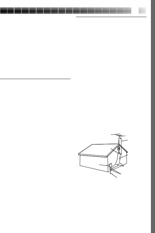
If an outside antenna or cable system is connected to the product, be sure the antenna or cable system is grounded so as to provide some protection against voltage surges and built-up static charges. Article 810 of the National Electrical Code, ANSI/NFPA 70, provides information with regard to proper grounding of the mast and supporting structure, grounding of the lead-in wire to an antenna discharge unit, size of grounding conductors, location of antenna discharge unit, connection to grounding electrodes, and
requirements for the grounding electrode.
2. Lightning
For added protection for this product during a lightning storm, or when it is left unattended and unused for long periods of time, unplug it from the wall outlet and disconnect the antenna or cable system. This will prevent damage to the product due to lightning and power-line surges.
3. Power Lines
An outside antenna system should not be located in the vicinity of overhead power lines or other electric light or power circuits, or where it can fall into such power lines or circuits. When installing an outside antenna system, extreme care should be taken to keep from touching such power lines or circuits as contact with them might be fatal.
EXAMPLE OF ANTENNA GROUNDING AS PER NATIONAL ELECTRICAL CODE, ANSI/NFPA 70
|
ANTENNA |
|
LEAD IN WIRE |
GROUND CLAMP |
|
|
ANTENNA |
|
DISCHARGE UNIT |
|
(NEC SECTION |
ELECTRIC SERVICE |
810-20) |
|
|
EQUIPMENT |
GROUNDING |
|
|
|
CONDUCTORS |
|
(NEC SECTION 810-21) |
|
GROUND CLAMPS |
POWER SERVICE GROUNDING ELECTRODE SYSTEM |
|
(NEC ART 250. PART H) |
|
NEC – NATIONAL ELECTRICAL CODE |
|
The product should be mounted to a wall or ceiling only as recommended by the manufacturer.

4


USE
1. Accessories
To avoid personal injury:
•Do not place this product on an unstable cart, stand, tripod, bracket or table. It may fall, causing serious injury to a child or adult, and serious damage to the product.
•Use only with a cart, stand, tripod, bracket, or table recommended by the manufacturer or sold with the product.
•Use a mounting accessory recommended by the manufacturer and follow the manufacturer’s instructions for any mounting of the product.
•Do not try to roll a cart with small casters across thresholds or deep-pile carpets.
2. Product and Cart Combination
A product and cart combination should be moved with care. Quick stops, excessive force, and uneven surfaces may cause the product and cart combination to overturn.
3.Water and Moisture
Do not use this product near water—for example, near a bath tub, wash bowl, kitchen sink or laundry tub, in a wet basement, or near a swimming pool and the like.
4.Object and Liquid Entry
PORTABLE CART WARNING (Symbol provided by RETAC)
Never push objects of any kind into this product through openings as they may touch dangerous voltage points or short-out parts that could result in a fire or electric shock. Never spill liquid of any kind on the product.
5. Attachments
Do not use attachments not recommended by the manufacturer of this product as they may cause hazards.
6. Cleaning
Unplug this product from the wall outlet before cleaning. Do not use liquid cleaners or aerosol cleaners. Use a damp cloth for cleaning.
7. Heat
The product should be situated away from heat sources such as radiators, heat registers, stoves, or other products (including amplifiers) that produce heat.
SERVICING
1. Servicing
If your product is not operating correctly or exhibits a marked change in performance and you are unable to restore normal operation by following the detailed procedure in its operating instructions, do not attempt to service it yourself as opening or removing covers may expose you to dangerous voltage or other hazards. Refer all servicing to qualified service personnel.
2. Damage Requiring Service
Unplug this product from the wall outlet and refer servicing to qualified service personnel under the following conditions:
a.When the power supply cord or plug is damaged.
b.If liquid has been spilled, or objects have fallen into the product.
c.If the product has been exposed to rain or water.
d.If the product does not operate normally by following the operating instructions. Adjust only those controls that are covered by the operating instructions as an improper adjustment of other controls may result in damage and will often require extensive work by a qualified technician to restore the product to its normal operation.
e.If the product has been dropped or damaged in any way.
f.When the product exhibits a distinct change in performance—this indicates a need for service.
3. Replacement Parts
When replacement parts are required, be sure the service technician has used replacement parts specified by the manufacturer or have the same characteristics as the original part. Unauthorized substitutions may result in fire, electric shock or other hazards.
4. Safety Check
Upon completion of any service or repairs to this product, ask the service technician to perform safety checks to determine that the product is in safe operating condition.

CAUTIONS 


 5
5
If you notice smoke or a peculiar smell coming from the VIDEO CAPTURE DOCKING STATION unplug it IMMEDIATELY. Use of the VIDEO CAPTURE DOCKING STATION under these conditions could lead to fire or electric shock. Contact your JVC dealer. DO NOT attempt to repair the malfunction yourself.
DO NOT attempt to insert foreign objects into the connectors, as this can lead to electric shock or fire. If an object is accidentally inserted, unplug it and contact your JVC dealer. Be especially careful with children.
If during use you notice that the VIDEO CAPTURE DOCKING STATION is damaged, unplug it and contact your JVC dealer. Use of the VIDEO CAPTURE DOCKING STATION under these conditions can lead to fire or electric shock.
DO NOT attempt to repair or modify the VIDEO CAPTURE DOCKING STATION. Doing so may result in malfunctions or injury. If a problem occurs, contact your JVC dealer.
Failure to heed the following precautions may result in damage to the VIDEO CAPTURE DOCKING STATION.
1.DO NOT place the VIDEO CAPTURE DOCKING STATION . . .
.... in an environment prone to extreme temperatures or humidity.
.... in direct sunlight.
.... in a dusty environment.
.... in an environment where strong magnetic fields are generated.
.... on a surface that is unstable or subject to vibration. The unit may fall, causing injury.
2.DO NOT place heavy objects on the VIDEO CAPTURE DOCKING STATION.
3.DO NOT place anything which might spill on top of the VIDEO CAPTURE DOCKING STATION.
4.AVOID violent shocks to the VIDEO CAPTURE DOCKING STATION during transport.
5.DO NOT leave the AC Adapter/charger plugged in when the VIDEO CAPTURE DOCKING STATION is not in use.
6.DO NOT use accessories other than those designated in the instructions. Use of others can lead to fire or electric shock.
7.DO NOT connect devices to the VIDEO CAPTURE DOCKING STATION other than those designated in the instructions. Use of others can lead to malfunctions.

6


 CAUTIONS
 (cont.)
How to handle a CD-ROM
cTake care not to soil or scratch the mirror surface (opposite to the printed surface). Do not write anything or put a sticker on either the front or back surface. If the CD-ROM gets dirty, gently wipe it with a soft cloth outward from the center hole using a circular motion.
cDo not use conventional disc cleaners or cleaning spray.
cDo not bend the CD-ROM or touch its mirror surface.
cDo not store your CD-ROM in a dusty, hot or humid environment. Keep it away from direct sunlight.
MAINTENANCE
If the inside of the VIDEO CAPTURE DOCKING STATION is left in a dusty environment for a long time, its use can lead to fire or malfunction. Consult your JVC dealer on cleaning.
CAUTION:
Changes or modifications not approved by JVC could void user’s authority to operate the equipment.
cThe Readme.TXT file provides additional information for setup and information that is not included in the instruction manual. Please read the file before installing the provided software program.
cYou can find the latest information (in English) on the provided software program at our world wide web server at http://www.jvc-victor.co.jp/
MAJOR FEATURES 


 7
7
Two software programs are provided with the GV-DS1 JLIP package.
JLIP Video Capture Software
(Z pg. 12 – 39)
JLIP Video Capture Software
This is the software described in this manual.
Video Capture Facility
Video images from video source units such as camcorders or VCRs can be captured as 640 x 480 still images with 16.77 million colors through the serial port (RS-232C) of a WindowsT-operated computer.
JLIP Control Facility
With a JLIP compatible camcorder or VCR,
•all basic video operations can be executed via the computer display;
•Up to 99 images can be captured automatically with Program Video Capture (playing tape — scanning — transferring to PC)
Data Sharing With JLIP Player Software
Data can be imported from the JLIP Player Software.
Data from the Video Capture Software can also be exported to the Player Software for Program Playback or Assemble Editing.
JLIP Player Software
(Z pg. 41 – 65)
JLIP Control Facility
With a JLIP-compatible camcorder, VCR or video printer (GV-PT1, GV-PT2):
•all basic video operations can be executed on the computer display;
•allows programmed video playback (up to 99 programs) or assemble editing
•allows image adjustment on the GV-PT1 video printer
•print command can be issued to the GVPT2 video printer
Data Sharing with the Video Capture Software
Video Capture Software data can be exported to the Player Software.
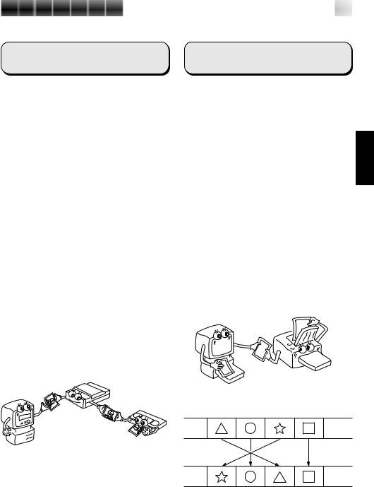
Assemble Editing
Selected scenes on a pre-recorded tape can be edited in a specified sequence.
Pre-recorded tape (on camcorder)
Recording tape (on VCR)

8


 CONTENTS
MAJOR FEATURES |
7 |
ADVANCED APPLICATIONS |
10 |
CONTROLS AND CONNECTORS |
11 |
CONNECTIONS (When Using JLIP Video Capture Software) |
12 |
INTRODUCTION |
14 |
INSTALLATION (JLIP Video Capture Software) |
15 |
HOW TO OPEN THE PROGRAM |
16 |
Preparation ................................................................... |
16 |
INITIALIZATION |
17 |
Initializing JLIP .............................................................. |
17 |
Select units .................................................................... |
18 |
HOW TO CLOSE THE PROGRAM |
19 |
HOW THE DESKTOP WORKS |
20 |
Main desktop window....................................................... |
20 |
Menu bar ...................................................................... |
21 |
VIDEO CAPTURE |
24 |
Capturing video images ..................................................... |
24 |
Step by step capture ......................................................... |
25 |
Automatic capture............................................................ |
26 |
Program capture ............................................................. |
26 |
Interval capture .............................................................. |
28 |
PICTURE FORMAT SETTING |
29 |
Selecting a picture format ................................................... |
29 |
ADDITIONAL OPERATIONS |
30 |
Counter value change ........................................................ |
30 |
Counter reset ................................................................. |
30 |
Delete index image and full image ......................................... |
31 |
Change ID ..................................................................... |
31 |
SAVE PICTURE |
32 |
Create new folder ............................................................ |
32 |
Saving ......................................................................... |
32 |
Open index .................................................................... |
33 |
Save the full image data .................................................... |
33 |

9
JLIP PLAYER SOFTWARE |
34 |
Using JLIP player software data ........................................... |
34 |
How to store JLIP player software data ................................. |
35 |
TROUBLESHOOTING |
36 |
LIST OF ERROR MESSAGES |
38 |
JLIP PLAYER SOFTWARE SECTION |
41 |
CONNECTIONS (When Using JLIP Player Software) |
42 |
When connecting to a video source unit with JLIP connector or to a |
|
video printer ................................................................ |
42 |
GETTING STARTED |
44 |
INSTALLING (JLIP Player Software) |
45 |
STARTING JLIP PLAYER SOFTWARE |
46 |
MOVIE PLAYER WINDOW BUTTONS AND DISPLAYS 48 |
|
BASIC OPERATIONS |
50 |
VIDEO PRINTER WINDOW BUTTONS AND DISPLAYS |
56 |
VIDEO PRINTER OPERATION (GV-PT1) |
58 |
Printing ........................................................................ |
58 |
Adjusting picture equalization .............................................. |
59 |
VIDEO PRINTER OPERATION (GV-PT2) |
60 |
Auto capture .................................................................. |
60 |
ADVANCED OPERATIONS |
62 |
Changing ID number ......................................................... |
62 |
Connecting other device during operation ................................. |
62 |
Changing the name of the device........................................... |
63 |
Changing the device to use while connecting over |
|
two same type devices ................................................... |
63 |
Adjusting the gap between the stored edit-start point in the |
|
computer and the dubbed one in the recording deck .................. |
64 |
TROUBLESHOOTING |
65 |
MAJOR SPECIFICATIONS |
66 |
INDEX |
67 |
10


 ADVANCED
 APPLICATIONS
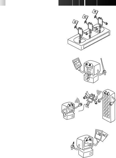
Create title indexes for your video collection
Title index images can be captured from your favorite recordings in intervals of 30 minutes, 1 hour, 1.5 hours, etc. using the Interval Capture mode. Print the captured index images on your PC printer using the computer's Print Screen facility, then attach them to your cassettes.
Business presentations
Images captured from video can be incorporated into business documents to spice up your presentations.
Internet homepage
Images captured from video can be incorporated in your Internet homepage using image editing software.
Video journal and postcards
Create your own original postcards, party invitation cards and the like or keep a video journal.
CONTROLS AND CONNECTORS 


 11
11
The controls and connectors marked * can be used only when the GR-DVM1 Digital Camcorder is attached. For details of its operation, read the camcorder instruction manual.
* Stop button |
|
|
|
|
|
|
|
|
|
* Play button |
||
|
|
|
|
|
|
|
|
|||||
* Rewind button |
|
|
|
|
|
|
|
|
|
* Pause button |
||
|
|
|
|
|
|
|
|
|
||||
* Fast forward button |
|
|
|
|
|
|
|
|
* Edit start button |
|||
|
|
|
|
|||||||||
|
|
|
|
|
|
|
|
|
|
|
|
|
* Lock lever |
* Unlock button |
* Digital jack Z p. 13 |
• Connect to the computer’s |
RS-232C terminal (COM |
port). |
* MULTI connector |
|
JLIP jack Z p. 13 |
|
||
• The Docking Station can be connected with |
|
(JLIP: Joint Level Interface Protocol) |
the GR-DVM1 through this connector. |
|
•Connect to a JLIP-compatible |
Never touch it with your hand or hit it with |
|
comcorder or VCR to control it from |
a hard object; if the pins are damaged, the |
|
the computer. |
connectors will become unusable due to |
|
|
contact failure. |
|
|
|
* DC output jack |
|
* S2 (Video) output jack |
•For dealer use. |
|
|
||
•Outputs the S-VIDEO signal. |
|
|
(Also compatible with S1 and S2 |
|
|
connectors.) |
|
|
DC input jack Z p. 13 |
|
|
* Video output jack |
* Remote control sensor |
|
* Audio output jack (Left) |
||
•Receives the remote |
||
|
||
* Audio output jack (Right) |
control signals for the |
|
|
attached Camcorder. |
|
|
* Edit jack |
Capture input (EXT.)/printer connector Z p. 13
•Connect with the video output (stored image output) of the optional video printer. Even when a TV is not connected to the video printer, this connection allows you to see the images output from the video printer on the LCD screen while printing.
•The date and timecode are not shown on the LCD screen. If you want to print out the date together with the images, connect a TV to the video output connector of the video printer and operate it by referring to the TV screen.
•It is also possible to capture images from video equipment other than the GR-DVM1by connecting the equipment to this connector. To make this operation possible, also attach the GR-DVM1 and set its power switch to record mode without loading a tape.
12


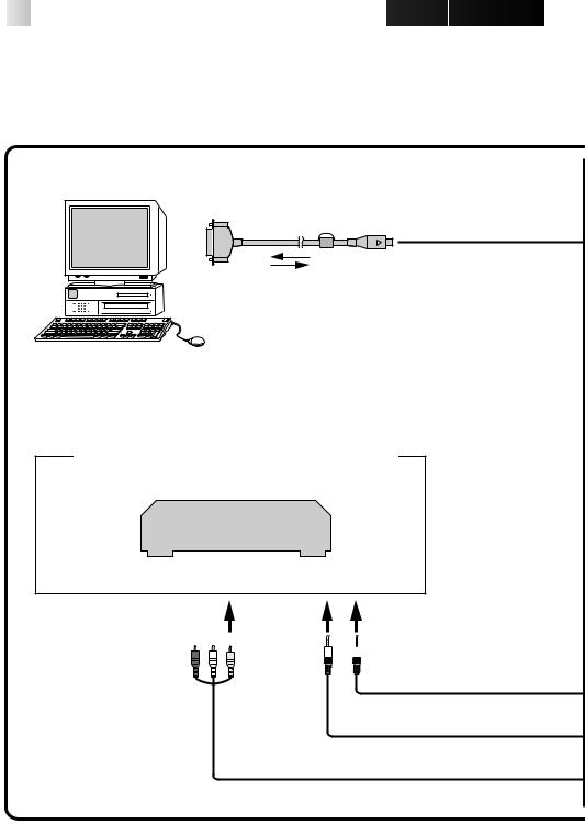
 CONNECTIONS
nTo assure safety, make sure all units are turned off before making any connections.
nThe video images will be displayed on the LCD screen of the attached GR-DVM1. You cannot view the images on the computer screen.
nWhen connecting the provided cables, be sure to connect the terminals equipped with Core filters to the Video Capture Docking Station.
nWhen using the Video Capture Docking Station, use the AA-V80U AC Adapter/Charger (optional or provided with the camcorder).
|
To Digital (8-pin) |
|
Core filter connector |
|
PC connection cable |
To COM |
(provided) |
(RS-232C) port |
|
Personal computer
Image sources with JLIP and video output connectors
VCR (Recording deck)
(red) (white) (yellow)

 To JLIP jack
To VIDEO output jack


 13
13
Video Capture
Docking Station
 JLIP
JLIP
 To JLIP
 jack
jack
Core filter
3.5 mm dia. 4-pole cables (provided)
AUDIO/VIDEO cable (provided)
Digital
Camcorder
AC Adapter/Charger
To DC output  jack
jack
Core filter |
DC cable (provided) |
|
(red) (white) (yellow)
|
To CAPTURE |
|
INPUT |
|
(EXT.)/ |
Core filter |
PRINTER |
connector |
Other units with video output jack

14


 INTRODUCTION
What is video capture software ?
Video capture software is a type of application program that allows you to capture video images from camcorders and VCRs and store them in personal computers running under the WindowsT operating system. These images can be transferred from the video source to the computer via a standard RS-232C communication interface. By processing the captured images with commercially available image editing software, you can create your own unique and highly personal illustrations and graphics for incorporation into everything from postcards to newsletters and Internet homepages.
What is JLIP ?
JLIP* stands for Joint Level Interface Protocol, a new communication protocol which allows AV units equipped with a JLIP terminal to be controlled by a personal computer.
* 


 is a registered trademark of JVC.
Operating Environment
cPersonal computer with MicrosoftT WindowsT 3.1 or WindowsT 95
cCPU Intel DX4™ or higher processor
cMinimum RAM requirement: more than 8 MB
cAvailable Hard Disk space of at least 8 MB
cColour display capable of at least 640 x 480 pixels, 256 colours Recommended 1024 x 768, 16.77 Mil colours
c1 free serial transmission port, compatible with 9600 bps transmission rate, connectable to RS-232C with 9 pin serial connector.
Recommended compatible with UART 16550A
cMouse (WindowsT compatible)
cCD-ROM drive
Note : An optional 9 pin serial conversion adapter is required for computers using serial communication port other than standard 9 pin.
*MicrosoftT and WindowsT are either registered trademarks or trademarks of Microsoft Corporation in the United States and/or other countries.
*Other product and company names included in this instruction manual are trademarks and/or registered trademarks of their respective holders.
Connectable Devices
When using JLIP with Video units equipped with a JLIP connector :
cJVC camcorders or VCRs equipped with a JLIP connector. When not using JLIP:
cVideo units with video output connectors

INSTALLATION (JLIP Video Capture Software) 
 15
15
WINDOWST 95 |
|
WINDOWST 3.1 |
Refer to the WindowsT 95 manual or your computer’s manual for details on basic WindowsT 95 operating procedures.
Installation Procedure
*To start the setup program...
1 Launch WindowsT 95
•Close any other applications that are running.
2 Insert the "JLIP Video Capture" CD-ROM into the CD-ROM drive.
3 Choose "Run" from "Start" on the taskbar.
4 If the "JLIP Video Capture" CD-ROM is in Drive D, type "D:\JCPTE\SETUP" in the box to the right of "Open". If the disk is in Drive E, type "E:\JCPTE\SETUP".
•Click "OK".
•Once the setup program is running, simply follow the instructions displayed on-screen.
•When setup is complete, the "JLIP Video Capture" icon appears on the screen.
•"JLIP Video Capture Setup was completed successfully." appears.
5 Click "OK" to complete installation.
Refer to the WindowsT 3.1 manual of or your computer manual for details on basic WindowsT 3.1 operating procedures.
Installation Procedure
*To start the setup program...
1 Launch WindowsT 3.1
•Close any other applications that are running.
2 Insert the "JLIP Video Capture" CD-ROM into the CD-ROM drive.
3 Choose "Run" from "File" in the "Program Manager".
4 If the "JLIP Video Capture" CD-ROM is in Drive D, type "D:\JCPTE\SETUP" in the box to the right of "Open". If the disk is in Drive E, type "E:\JCPTE\SETUP".
•Click "OK".
•Once the setup program is running, simply follow the instructions displayed on-screen.
•When setup is complete, the "JLIP Video Capture" icon appears on the screen.
•"JLIP Video Capture Setup was completed successfully." appears.
5 Click "OK" to complete installation.

16


 HOW
HOW
 TO
TO OPEN
OPEN THE
THE PROGRAM
The Video Capture software can be started up in the same way as any other program running under Windows. The procedure differs slightly depending on whether you’re using WindowsT 3.1 or WindowsT 95.
Preparation
•Turn on your computer.
•Press the POWER button to turn on the power.
•Turn on the video source units (such as camcorders and VCRs).
•If you want to capture a still picture from a recorded tape, load the tape into the video unit.
•If you want to capture an image from the data stored in the JLIP Player Software, be sure to load the disk on which the image is stored.
Close any programs that are running. You cannot run other programs simultaneously with the Video Capture software.
With WindowsT 3.1, open the group of application icons in the Program Manager and double-click the application icon you want to launch.
With WindowsT 95, click the [START] button on the taskbar, and the Program menu appears on the screen. Move the mouse pointer over the program entry you want to run and click to start the program.
Now let’s start the program.
If you’re using WindowsT 3.1, open the JLIP Video Capture group in the "Program Manager" and double-click the JLIP Video Capture icon.
If you’re using WindowsT 95, select JLIP Video Capture from the "Start menu" and click to start.

INITIALIZATION


 17
17
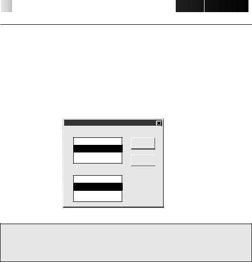
INITIALIZING JLIP
The first time you start the Video Capture software, JLIP initialization is required. This sets which of the computer’s COM ports (connector into which the RS-232C cable is plugged) is connected to the GV-CB1 JLIP Video Capture Docking Station. The initialization window automatically appears the first time you start the software after installation. Do not forget to carry out this JLIP initialization procedure. The JLIP must be initialized again whenever you connect a new image source or other unit to the JLIP Video Capture Docking Station.
1.
2.
3.
4.
Start the JLIP Video Capture software.
The "JLIP Initialization" screen automatically appears.
Select "COM Port".
•COM1 through COM4 ports are available. Check to see which COM port is connected to the JLIP Video Capture Box and select it.
Select "Transfer Rate". •Normally select 38400.
•38400 may not be available on some computers. When transmission errors take place during use, switch to 19200 or 9600. Image data transmission will be slower at these speeds.
5. Click "OK". The "JLIP Initialization" window appears while the program checks for the connected units.
JLIP Initialization |
|
|
COM Port |
COM 1 |
OK |
Transfer Rate |
38400 |
Cancel |
NOTE : If you want to change a unit or COM port or Transfer Rate, select "Initialize" from "Set-up" in the menu bar to call up the "JLIP Initialization" window. Repeat this setting procedure.
If a connection is incorrect, a connected unit is not turned on, or the connection ID numbers overlap, the message "Connection error" appears. Click "OK" to return to the Main desktop.
18


 INITIALIZATION
SELECT UNITS
6.
7.
8.
The "Device Selection" window appears, listing the JLIP devices.
Click the name of the desired unit.
•The word "VCRCAMERA" appears in the VCR box to indicate the Video source unit is now in use.
•The word "MODULE" appears in the Video Capture box to indicate the Video Capture Docking Station is now in use.
•Only one VCR and one Video Capture device can be selected.
Click "OK".
•The main desktop window returns (setting complete).
Device Selection
VCR
Not connected OK 06:VCRCAMERA
Cancel 
Video Capture
Not connected
83:MODULE
NOTE : The "Device Selection" window automatically appears when JLIP initialization is complete. However, if you want to select equipment whose JLIP initialization has already been carried out, select "Device Change" from "Set-up" in the menu bar to call up the "Device Selection" window.

HOW TO CLOSE THE PROGRAM 


 19
19
Double-click the control menu button in WindowsT 3.1 or click "Exit" in the "File" menu.
In WindowsT 95, simply click the Close button.
If you try to close the program with no image saved, the message "The album has not been saved. Save?" appears. Please note that if you close without saving, all unsaved captured data will be deleted.
1Click "Exit" from "File" in the menu bar. •The program closes.
File
New Album
Open Album
Save Album Ctrl+S
Open JLIP (jlp) File
Save As JLIP (jlp) File
Save Image As… |
Ctrl+A |
Exit
20


 HOW
HOW

 THE
THE DESKTOP
 WORKS
WORKS
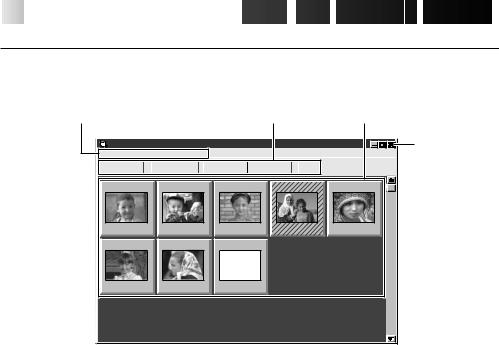
MAIN DESKTOP WINDOW
1.Menu bar |
|
|
|
2. Control |
3.Image display area |
||
|
|
|
|
|
buttons |
Close |
|
JLIP Video Capture [–Untitled Folder–] (Untitled) |
|
|
|
|
|||
File Edit Set-up |
Window Help |
|
|
|
|
|
button |
CAPTURE |
TRANSFER |
MEMORY |
INPUT |
JLIP |
|
||
|
|
||||||
01 |
02 |
03 |
|
|
04 |
|
05 |
00:01:23:12 |
00:02:17:21 |
00:07:01:19 |
00:37:05:06 |
00:20:39:18 |
|||
06 |
07 |
08 |
|
|
|
|
|
00:39:03:11 |
00:47:53:03 |
- - : - - : - - : - - |
|
|
|
|
|
1
2
Menu bar
Displays function menus. See the next page for detailed information.
Control buttons
•CAPTURE button (Z page 25)
Press to CAPTURE a desired image from an image source. When pressed, an index image appears under this button.
•TRANSFER button (Z pages 27, 28)
The TRANSFER button is used to start Automatic Transfer. Automatic Transfer is divided
into Program Capture and Interval Capture.
•MEMORY/INPUT button
Press to switch between the image stored in this unit and the image from the video source.
•JLIP button (Z pages 41 through 65)
The JLIP Video Capture software and JLIP Player software cannot run simultaneously. When you want to run the JLIP Player software, press this button to disable the JLIP Video Capture software. You may then start the JLIP Player software. To resume using the JLIP Video Capture software, first select "Close Serial" from "File" on the JLIP Player Software's menu bar, then press the JLIP button.


 21
21
3 Image display area
Each time you press the Capture button an image is captured by this device. An index image is transferred to the computer and displayed in the image area. Up to 99 images can be captured, with up to five images per line. Index images are provided to allow you to confirm that you have captured the images you want.
Index image: 80 x 60 pixels Full image: 640 x 480 pixels
Image display box |
|
Click to select an image display box, and |
|
• the border turns green |
|
• Double-click an image display box, and Full |
Index numbers are |
image data will appear if it has already been |
automatically assigned |
transferred |
|
02 |
03 |
04 |
00:02:17:21 |
00:07:01:19 |
00:37:05:06 |
Counter display
Indicates the current tape position eg. 00 : 12 : 17 : 21
Hour : Min : Sec : Frame
Colours of counter numerals |
Hatched like this when |
Black : Full image transferred |
the counter time has been |
White : Full image not transferred |
changed (Z p. 30) |
(only index image |
|
transferred) |
|
MENU BAR
All program functions can be selected from the menus in the menu bar. Click any item in the menu bar to open the corresponding pulldown menu. Then click the desired command in the pulldown menu. Some menu entries are invalid depending on the program status. Invalid commands appear lighter than valid commands.
|
|
|
JLIP Video Capture |
|
|
||||||
|
|
|
|
|
|||||||
|
|
|
|
|
|||||||
|
|
|
|
|
|
|
|
|
|
|
|
|
File |
Edit Set-up |
Window Help |
|
|
||||||
|
|
|
|
|
|
|
|
|
|
|
|
|
|
New Album |
|
|
|
|
MEMORY |
INPUT |
|
||
|
|
Open Album |
|
|
|
|
|
||||
|
|
Save Album |
Ctrl+S |
|
|
|
|||||
|
|
Open JLIP (jlp) File |
|
|
|
||||||
|
|
Save As JLIP (jlp) File |
|
|
|
||||||
|
|
Save Image As… |
Ctrl+A |
|
|
|
|||||
|
|
Exit |
|
|
|
|
|
||||
|
|
|
|
|
|
|
|
|
|
|
|
 Loading...