


ENGLISH
|
|
|
|
|
CONTENTS |
|
|
|
|
|
|
|
AUTOMATIC DEMONSTRATION |
6 |
|||
|
|
|
|
GETTING STARTED |
|
7 – 14 |
||
|
DIGITAL VIDEO CAMERA |
|
|
|
|
|
||
|
TAPE |
|
|
|
|
|||
|
RECORDING & PLAYBACK |
15 – 24 |
||||||
|
|
|
|
TAPE |
RECORDING ........................ |
|
16 – 20 |
|
|
GR-DVL1020 |
|
||||||
|
TAPE |
PLAYBACK |
.......................... |
|
21 – 24 |
|||
|
|
|
||||||
|
RECORDING & PLAYBACK |
25 – 36 |
||||||
|
|
|
|
MEMORY CARD |
|
|
||
|
GR-DVL820 |
|
|
|
||||
|
ADVANCED FEATURES .................... |
|
30 – 36 |
|||||
|
|
|
|
MEMORY CARD |
RECORDING ......... |
|
26 – 27 |
|
|
|
|
|
MEMORY CARD |
PLAYBACK ............ |
|
28 – 29 |
|
|
GR-DVL520 |
|
|
|
|
|||
|
FOR RECORDING |
........................... |
|
38 – 45 |
||||
|
|
|
|
ADVANCED FEATURES |
37 – 66 |
|||
|
GR-DVL320 |
USING MENUS FOR |
|
54 – 64 |
||||
|
USING THE REMOTE CONTROL UNIT ... |
|
||||||
|
|
|
|
DETAILED ADJUSTMENT .............. |
|
46 – 51 |
||
|
|
|
|
DUBBING ..................................... |
|
|
52 – 53 |
|
|
|
|
|
SYSTEM CONNECTIONS .................. |
|
65 – 66 |
||
|
|
|
|
|
|
|||
|
|
|
|
REFERENCES |
67 – Back Cover |
|||
|
|
|
|
DETAILS ............................................. |
|
|
68 |
|
|
|
|
|
TROUBLESHOOTING ...................... |
|
69 – 73 |
||
|
|
|
|
USER MAINTENANCE ............................ |
|
74 |
||
|
|
|
|
CAUTIONS |
|
|
75 – 77 |
|
|
Please visit our Homepage on the World Wide Web and |
|
|
|||||
|
SPECIFICATIONS ........................... |
|
|
78 – 79 |
||||
|
answer our Consumer Survey (in English only): |
INDEX |
|
|
|
80 – 86 |
||
|
|
|
|
......................................... |
|
|
||
|
http://www.jvc-victor.co.jp/english/index-e.html |
|
|
TERMS ............................... |
87 – Back Cover |
|||
|
|
|
|
|
|
|
|
|
For Accessories:
http://www.jvc-victor.co.jp/english/accessory/
The camcorder illustrations appearing in this instruction manual are of the GR-DVL1020.
Memory card recording features are available on GR-DVL1020, GR-DVL820 and GR-DVL520
INSTRUCTIONS
LYT0963-001A EN

S
SD Memory Card .................................. |
Z pg. 14, 76 |
Self-Recording ............................................ |
Z pg. 17 |
Sepia ........................................................... |
Z pg. 39 |
Set Remote Control/VCR Code .................. |
Z pg. 58 |
Shuttle Search ............................................ |
Z pg. 21 |
Shutter Speed ............................................. |
Z pg. 39 |
Slow-Motion Playback ........................... |
Z pg. 21, 56 |
Slow Shutter ................................................ |
Z pg. 39 |
Snapshot ............................................... |
Z pg. 26, 42 |
Snapshot Mode ........................................... |
Z pg. 42 |
Snow ........................................................... |
Z pg. 39 |
Sound Mode .................................... |
Z pg. 47, 50, 51 |
Speaker Volume .......................................... |
Z pg. 21 |
Specifications ........................................ |
Z pg. 78, 79 |
Sports .......................................................... |
Z pg. 39 |
Spotlight ...................................................... |
Z pg. 39 |
Squeeze ...................................................... |
Z pg. 48 |
Still Playback ............................................... |
Z pg. 21 |
Strobe ......................................................... |
Z pg. 39 |
T
Tally ............................................................. |
Z pg. 48 |
|
Tele Macro .................................................. |
Z pg. 48 |
|
Time Code ..................................... |
Z pg. 20, 49 – 51 |
|
Tripod Mounting .......................................... |
Z pg. 10 |
|
Twilight ........................................................ |
Z pg. 39 |
|
|
|
|
U |
|
|
Unload A Tape ............................................. |
Z pg. 12 |
|
|
|
|
V |
|
|
VIDEO/MEMORY Switch Position .............. |
Z pg. 17 |
|
Video Light .................................................. |
Z pg. 19 |
|
|
|
|
W |
|
|
WebCam ..................................................... |
Z pg. 66 |
|
White Balance ............................................. |
Z pg. 45 |
|
Wide Mode .................................................. |
Z pg. 48 |
|
Wind Cut ..................................................... |
Z pg. 48 |
|
Wipe In/Out ........................................... |
Z pg. 40, 41 |
|
|
|
|
Z |
|
|
Zooming ...................................................... |
Z pg. 18 |
|
See previous page as well.
VICTOR COMPANY OF JAPAN, LIMITED
|
|
Printed in Japan |
COPYRIGHT© 2002 VICTOR COMPANY OF JAPAN, LTD. |
A/A-S/EA |
0202HOV*ID*VP |
|
2 EN
Dear Customer,
Thank you for purchasing this digital video camera. Before use, please read the safety information and precautions contained in the following pages to ensure safe use of this product.
Using This Instruction Manual
•All major sections and subsections are listed in the Table Of Contents on the cover page.
•Notes appear after most subsections. Be sure to read these as well.
•Basic and advanced features/operation are separated for easier reference.
It is recommended that you . . .
..... refer to the Index (Z pgs. 80 – 86) and familiarize yourself with button locations, etc. before use.
..... read thoroughly the Safety Precautions. They contain extremely important information regarding the safe use of this product.
You are recommended to carefully read the cautions on pages 75 through 77 before use.
SAFETY PRECAUTIONS
WARNING:
TO PREVENT FIRE OR SHOCK HAZARD, DO NOT EXPOSE THIS UNIT TO RAIN OR MOISTURE.
CAUTIONS:
cIf you notice smoke or a peculiar smell coming from the camcorder or AC Adapter, shut it down and unplug it immediately. Continue using the camcorder or AC Adapter under these conditions could lead to fire or electric shock. Contact your JVC dealer. Do not attempt to repair the malfunction yourself.
cTo prevent shock, do not open the cabinet. No user serviceable parts inside. Refer servicing to qualified personnel.
cWhen you are not using the AC Adapter for a long period of time, it is recommended that you disconnect the power cord from AC outlet.
NOTES:
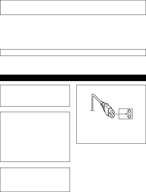
cThe rating plate (serial number plate) and safety caution are on the bottom and/or the back of the main unit.
cThe rating information and safety caution of the AC Adapter are on its upper and lower sides.
CAUTION:
To avoid electric shock or damage to the unit, first firmly insert the small end of the power cord into the AC Adapter until it is no longer wobbly, and then plug the larger end of the power cord into an AC outlet.

EN 3
CAUTIONS:
cThis camcorder is designed to be used with PAL-type colour television signals. It cannot be used for playback with a television of a different standard. However, live recording and LCD monitor/viewfinder playback are possible anywhere.
cUse the JVC BN-V408U/V416U/V428U battery packs and, to recharge them or to supply power to the camcorder from an AC outlet, use the provided multi-voltage AC Adapter and Power Cord. (An appropriate conversion adapter may be necessary to accommodate different designs of AC outlets in different countries.)
When the equipment is installed in a cabinet or on a shelf, make sure that it has sufficient space on all sides to allow for ventilation (10 cm or more on both sides, on top and at the rear).
Do not block the ventilation holes.
(If the ventilation holes are blocked by a newspaper, or cloth etc. the heat may not be able to get out.)
No naked flame sources, such as lighted candles, should be placed on the apparatus.
When discarding batteries, environmental problems must be considered and the local rules or laws governing the disposal of these batteries must be followed strictly.
The apparatus shall not be exposed to dripping or splashing.
Do not use this equipment in a bathroom or places with water.
Also do not place any containers filled with water or liquids (such as cosmetics or medicines, flower vases, potted plants, cups etc.) on top of this unit.
(If water or liquid is allowed to enter this equipment, fire or electric shock may be caused.)

4 EN
SAFETY PRECAUTIONS
Do not point the lens or the viewfinder directly into the sun. This can cause eye injuries, as well as lead to the malfunctioning of internal circuitry. There is also a risk of fire or electric shock.
CAUTION!
The following notes concern possible physical damage to the camcorder and to the user.
When carrying, be sure to always securely attach and use the provided shoulder strap. Carrying or holding the camcorder by the viewfinder and/or the LCD monitor can result in dropping the unit, or in a malfunction.
Take care not to get your finger caught in the cassette holder cover. Do not let children operate the camcorder, as they are particularly susceptible to this type of injury.
Do not use a tripod on unsteady or unlevel surfaces. It could tip over, causing serious damage to the camcorder.
CAUTION!
Connecting cables (Audio/Video, S-Video, etc.) to the camcorder and leaving the unit on top of the TV is not recommended, as tripping on the cables will cause the camcorder to fall, resulting in damage.
nThis camcorder is designed exclusively for the digital video cassette, SD Memory Card and
MultiMediaCard. Only cassettes marked “

 ” and memory cards* marked “

 ” or “


 ” can be used with this unit.
Before recording an important scene . . .
.... make sure you only use cassettes with the Mini DV mark |
. |
|
.... make sure you only use memory cards* with the mark |
or |
. |
.... remember that this camcorder is not compatible with other digital video formats.
.... remember that this camcorder is intended for private consumer use only. Any commercial use without proper permission is prohibited. (Even if you record an event such as a show, performance or exhibition for personal enjoyment, it is strongly recommended that you obtain permission beforehand.)
* Memory cards can be used with GR-DVL1020/DVL820/DVL520 only.
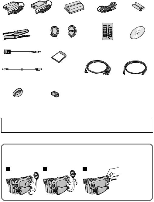
PROVIDED ACCESSORIES |
EN 5 |
or
AC Adapter AP-V10EG or |
Battery Pack |
|
BN-V408U |
||
AP-V12EG |
||
|
||
|
or |
|
Shoulder Strap |
Lens Cap |
|
(See below for |
||
|
||
|
attachment) |
|
PC Connection Cable |
|
|
(GR-DVL320 only) |
|
|
|
Memory Card 8 MB |
|
|
(GR-DVL1020/DVL820/ |
|
USB Cable (GR-DVL1020/ |
DVL520 only) (Already |
|
inserted in the |
||
DVL820/DVL520 only) |
||
camcorder) |
Lens hood (Already |
Core Filter x 1 |
attached to the camcorder; |
(for optional S-Video |
GR-DVL1020/DVL820 only) |
cable Z pg. 6 for |
|
attachment) |
Power Cord
Remote
Control Unit
RM-V717U
Audio/Video Cable (ø3.5 mini-plug to RCA plug)
AAA (R03) Battery x 2 (for remote control unit)
CD-ROM
Editing Cable
GR-DVL320:
One plug has 3 rings around the pin, and the other has 1 ring around the pin.
GR-DVL1020/DVL820/ DVL520:
Both plugs have 1 ring around the pin.
NOTE:
In order to maintain optimum performance of the camcorder, provided cables may be equipped with one or more core filter. If a cable has only one core filter, the end that is closest to the filter should be connected to the camcorder.
How To Attach The Lens Cap
To protect the lens, attach the provided lens cap to the camcorder as shown in the illustration.
NOTE:
To confirm the lens cap is on correctly make sure the cap is flush to the camera.
1 |
2 |
3 |
For GR-DVL1020/ |
|
|
|
DVL820 Owners: |
The lens cap can be attached only when the lens hood is attached to the camcorder.
6 EN
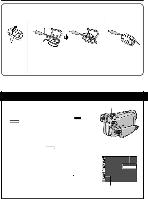
How To Attach The Core Filter
Attach the Core Filter(s) (if provided with your model Z pg. 5) to an optional cable(s). The Core Filter reduces interference.
12
3 cm
Stopper |
|
|
Wind once |
|
|
||
|
|
|
|
Release the |
Run the cable through the Core Filter, leaving approx. |
||
stoppers on both |
3 cm of cable between the cable plug and the Core Filter. |
||
ends of the Core |
Wind the cable once around the outside of the Core Filter |
||
Filter. |
as shown in the illustration. |
||
|
• Wind the cable so that it is not slack. |
||
|
NOTE: |
||
|
Take care not to damage the cable. |
||
3
Close the Core Filter until it clicks shut.
n When connecting cables, attach the end with the Core Filter to the camcorder.
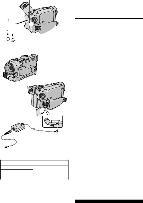
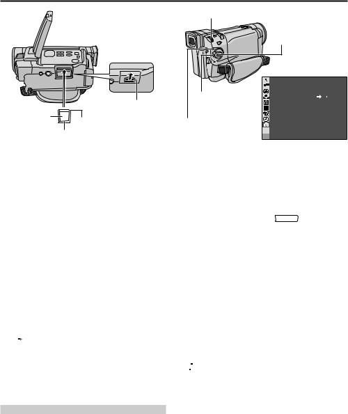
AUTOMATIC DEMONSTRATION
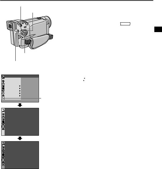
Automatic Demonstration takes place when “DEMO MODE” is set to “ON” (factory-preset).
nAutomatic Demonstration starts when there is no operation for about 3 minutes after the Power Switch is set to “ AUTO ” or
“ MANUAL ” and no cassette is in the camcorder.
nPerforming any operation during the demonstration stops the demonstration temporarily. If no operation is performed for more than 3 minutes after that, the demonstration will resume.
n“DEMO MODE” remains “ON” even if the camcorder power is turned off.
nTo cancel Automatic Demonstration:
1. Set the Power Switch to “ |
MANUAL |
” while pressing down the |
|
|
Lock Button located on the switch and press the MENU/ BRIGHT wheel in. The Menu Screen appears.
2. Rotate the MENU/BRIGHT wheel to select “  SYSTEM” and press it. The SYSTEM Menu appears.
3.Rotate the MENU/BRIGHT wheel to select “DEMO MODE” and press it. The Sub Menu appears.
4.Rotate the MENU/BRIGHT wheel to select “OFF” and press
5. Rotate the MENU/BRIGHT wheel to select “ 


 RETURN”, and press it twice. The normal screen appears.
NOTE:
If you do not detach the Lens Cap, you cannot see the actual changes of the Automatic Demonstration activated on the LCD monitor or viewfinder.
MENU/BRIGHT Wheel
Power Switch |
Lock Button |
Sub Menu
DEMO MODE – OF F
ON
GR-DVL1020/DVL820/DVL520 only

GETTING STARTED |
EN 7 |
GETTING STARTED |
|
CONTENTS |
|
Power .................................................. |
8 – 9 |
Grip Adjustment ......................................... |
10 |
Viewfinder Adjustment .................................. |
10 |
Shoulder Strap Attachment ............................. |
10 |
Tripod Mounting .......................................... |
10 |
Date/Time Settings...................................... |
11 |
Loading/Unloading A Cassette ......................... |
12 |
Recording Mode Setting ................................. |
13 |
Loading A Memory Card |
|
(GR-DVL1020/DVL820/DVL520 only) ....................... |
14 |
Picture Quality/Image Size Setting |
|
(GR-DVL1020/DVL820/DVL520 only) ....................... |
14 |
8 EN |
GETTING STARTED (cont.) |
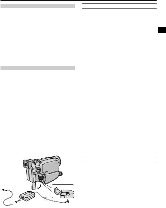
BATT. RELEASE Button
1


 2
2 
 3
3


Power Switch
CHARGE Lamp
Battery pack 
AC Adapter
5 |
4 |
To DC |
|
|
connector |
6To AC outlet |
|
Power
This camcorder’s 2-way power supply system lets you choose the most appropriate source of power. Do not use provided power supply units with other equipment.
CHARGING THE BATTERY PACK
1 Tilt the viewfinder upward 1. With the arrow on the battery pack pointing downward, push the battery pack slightly against the battery pack mount 2, then slide down the battery pack until it locks in place 3.
2 Set the Power Switch to “OFF”. Connect the AC Adapter to the camcorder 4, then connect the Power Cord to the AC Adapter 5.
3 Plug the Power Cord into an AC outlet 6. The CHARGE lamp on the camcorder blinks to indicate charging has started.
4 When the CHARGE lamp stops blinking but stays lit, charging is finished. Unplug the Power Cord from the AC outlet. Disconnect the AC Adapter from the camcorder.
To Detach The Battery Pack . . .
..... Press BATT. RELEASE and pull out the battery pack.
NOTES:
cIf the protective cap is attached to the battery pack, remove it first.
cDuring charging, the camcorder cannot be operated.
cCharging is not possible if the wrong type of battery is used.
cWhen charging the battery pack for the first time or after a long storage period, the CHARGE lamp may not light. In this case, remove the battery pack from the camcorder, then try charging again.
cIf the battery operation time remains extremely short even after having been fully charged, the battery is worn out and needs to be replaced. Please purchase a new one.
cUsing the optional AA-V40 AC Power Adapter/Charger, you can charge the BN-V408U/V416U/V428U battery pack without the camcorder. However, it cannot be used as an AC adapter.
Battery pack
BN-V408U
BN-V416U (optional)
BN-V428U (optional)
Charging time
approx. 1 hr. 30 min.
approx. 3 hrs.
approx. 5 hrs.
For other notes, Z pg. 68
EN 9
ATTENTION
Before detaching the power source, make sure that the camcorder’s power is turned off. Failure to do so can result in a camcorder malfunction.
NOTES:
cRecording time is reduced significantly under the following conditions:
•Zoom or Record-Standby mode is engaged repeatedly.
•The LCD monitor is used repeatedly.
•The playback mode is engaged repeatedly.
cBefore extended use, it is recommended that you prepare enough battery packs to cover 3 times the planned shooting time.
INFORMATION
The extended-use battery pack kit is a set composed of a battery pack and AC Power Adapter/Charger: VU-V840 KIT : BN-V840U battery pack & AA-V15 AC
Power Adapter/Charger
VU-V856 KIT : BN-V856U battery pack & AA-V80 AC Power Adapter/Charger
Read the kit's instruction manual before using. Also, by using the optional JVC VC-VBN856U DC
Cord, it will be possible to connect BN-V840U or BNV856U battery packs to the camcorder and supply power directly to the camcorder.
USING THE BATTERY PACK
Perform step 1 of “CHARGING THE BATTERY PACK” (Z pg. 8).
Approximate recording time <GR-DVL520/DVL320>
|
Battery pack |
LCD monitor on |
Viewfinder on |
|
|
|
|
|
|
|
BN-V408U |
1 hr. |
1 hr. 15 min. |
|
|
|
(35 min.) |
(40 min.) |
|
|
|
|
|
|
|
BN-V416U |
2 hrs. |
2 hrs. 30 min. |
|
|
(optional) |
(1 hr. 10 min.) |
(1 hr. 20 min.) |
|
|
|
|
|
|
|
BN-V428U |
3 hrs. 30 min. |
4 hrs. 20 min. |
|
|
(optional) |
(2 hrs.) |
(2 hrs. 20 min.) |
|
|
|
|
|
|
|
BN-V840U |
5 hrs. |
6 hrs. 10 min. |
|
|
(optional) |
(2 hrs. |
50 min.) |
(3 hrs. 20 min.) |
|
|
|
|
|
|
BN-V856U |
7 hrs. |
8 hrs. 40 min. |
|
|
(optional) |
(4 hrs.) |
(4 hrs. 40 min.) |
|
|
|
|
|
|
( |
) : when the video light is on |
|
||
Approximate recording time |
|
|||
<GR-DVL1020/DVL820> |
|
|||
|
|
|
|
|
|
Battery pack |
LCD monitor on |
Viewfinder on |
|
|
|
|
|
|
|
BN-V408U |
55 min. |
1 hr. 10 min. |
|
|
|
(35 min.) |
(45 min.) |
|
|
|
|
|
|
|
BN-V416U |
1 hr. 55min. |
2 hrs. 25 min. |
|
|
(optional) |
(1 hr. 15 min.) |
(1 hr. 30 min.) |
|
|
|
|
|
|
|
BN-V428U |
3 hrs. |
25 min. |
4 hrs. 20 min. |
|
(optional) |
(2 hrs. |
15 min.) |
(2 hrs. 40 min.) |
|
|
|
|
|
|
BN-V840U |
4 hrs. |
25 min. |
5 hrs. 40 min. |
|
(optional) |
(2 hrs. |
55 min.) |
(3 hrs. 30 min.) |
|
|
|
|
|
|
BN-V856U |
6 hrs. |
40 min. |
8 hrs. 30 min. |
|
(optional) |
(4 hrs. 15 min.) |
(5 hrs. 5 min.) |
|
|
|
|
|
|
( |
) : when the video light is on |
|
||
To AC outlet
 AC Adapter
USING AC POWER
Use the AC Adapter (connect as shown in the illustration).
NOTES:
c The provided AC Adapter features automatic voltage selection in the AC range from 110 V to 240 V.
c For other notes, Z pg. 68.
To DC connector
10 EN
Power
Zoom Lever
Recording
Start/Stop button
Power Switch
Dioptre
Adjustment Control
PAUSE
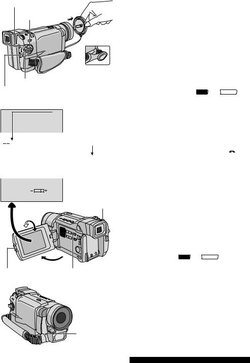
GETTING STARTED (cont.)
Grip Adjustment
1
2 Pass your right hand through the loop and grasp the grip.
3 Adjust your thumb and fingers through the grip, to easily operate the Recording Start/Stop button and Power Switch and Power Zoom Lever. Be sure to fasten the Velcro strip to your preference.
Viewfinder Adjustment
1 Set the Power Switch to “ |
AUTO |
” or “ |
MANUAL |
” |
while pressing down the Lock Button located on the switch.
2 Turn the Dioptre Adjustment Control until the indications in the viewfinder are clearly focused.
|
Shoulder Strap Attachment |
|
1 Make sure the battery pack is removed. Following |
2 |
the illustration, thread the strap through the eyelet 1, |
then fold it back and thread it through the buckle 2. |
|
|
Repeat the procedure to attach the other end of the |
1 |
strap to the other eyelet 3 located under the Grip |
Strap. Confirm the strap is not twisted. |
3
Tripod Mounting
CAUTION
When attaching the camcorder to a tripod, extend its legs to stabilise the camcorder. It is not advised to use small sized tripods. This may cause damage to the unit by falling over.
1 To attach the camcorder to a tripod, align the direction stud and screw to the mounting socket and stud hole on the camcorder. Then tighten the screw clockwise. Some tripods are not equipped with studs.
EN 11
MENU/BRIGHT Wheel
Power Lamp
Power Switch |
Lock Button
Display
|
|
W IPE / FADER |
|
OF F |
|
|
|
PROGRAM AE |
|
|
|
|
|
|
|||
|
|
EXPOSURE |
|
|
|
|
|
W. BALANCE |
|
|
|
|
|
CAMERA |
|
|
|
|
MANUAL |
|
|
||
|
|
SYSTEM |
|
|
|
|
|
D I SPLAY |
|
|
|
|
|
DSC |
|
|
|
|
|
END |
|
|
|
|
|
|
|
||
|
|
ON SCREEN |
– |
LCD / TV |
|
|
|
||||
|
|
||||
|
|||||
|
|
|
DATE / T I ME |
– |
AUTO |
|
|
|
T I ME CODE |
– |
OFF |
|
|
|
CLOCK |
|
2 5 . 12 . 02 |
|
|
|
ADJ . |
|
17 : 3 0 |
|
|
|
|
||
GR-DVL1020/DVL820/
DVL520 only
DISPLAY Menu

 RETURN
|
|
CLOCK |
|
|
|
|
|
|
|
|
|
|
|
|
|
|
|
|
|
|
|
|
|
2 5 |
. 12 |
. 02 |
|
|
|
ADJ . |
|
|
17 |
: 3 0 |
|
|
|
|
|
|
|
Date/Time Settings
The date/time is recorded onto the tape at all times, but its display can be turned on or off during playback (Z pg. 50, 51).
1 Set the Power Switch to “ |
MANUAL |
” while pressing |
|
|
down the Lock Button located on the switch. The power lamp lights and the camcorder is turned on.
2 Press the MENU/BRIGHT wheel in to access the Menu Screen.
3 Rotate the MENU/BRIGHT wheel to select
“  DISPLAY”. Press it and the DISPLAY Menu appears.
4 Rotate the MENU/BRIGHT wheel to select “CLOCK ADJ.”. Press it and “day” is highlighted. Rotate the MENU/BRIGHT wheel to input the day. Press it. Repeat to input the month, year, hour and minute.
Rotate the MENU/BRIGHT wheel to select
“ 


 RETURN”, and press it twice. The Menu Screen closes.
NOTE:
Even if you select “CLOCK ADJ.”, if the parameter is not highlighted the camcorder’s internal clock continues to operate. Once you move the highlight bar to the first date/ time parameter (day), the clock stops. When you finish setting the minute and press the MENU/BRIGHT wheel in, the date and time begin operation from the date and time you just set.
12 EN |
GETTING STARTED (cont.) |
Erase protection tab*
Make sure the window side is facing out.
Cassette holder
OPEN/EJECT |
Switch |
Cassette holder cover |
PUSH HERE
Loading/Unloading A Cassette
The camcorder needs to be powered up to load or eject a cassette.
1 Slide and hold OPEN/EJECT in the direction of the arrow then pull the cassette holder cover open until it locks. The cassette holder opens automatically.
• Do not touch internal components.
2 Insert or remove a tape and press “PUSH HERE” to close the cassette holder.
•Once the cassette holder is closed, it recedes automatically. Wait until it recedes completely before closing the cassette holder cover.
•When the battery’s charge is low, you may not be able to close the cassette holder cover. Do not apply force. Replace the battery with a fully charged one before continuing.
3 Close the cassette holder cover firmly until it locks into place.
* To Protect Valuable Recordings . . .
.... slide the erase protection tab on the back of the tape in the direction of “SAVE”. This prevents the tape from being recorded over. To record on this tape, slide the tab back to “REC” before loading it.
Be sure to press only the section labeled “PUSH HERE” to close the cassette holder; touching other parts may cause your finger to get caught in the cassette holder, resulting in injury or product damage.
NOTES:
Approximate recording time
Tape |
Recording mode |
||
|
|
||
SP |
LP |
||
|
|||
|
|
|
|
30 min. |
30 min. |
45 min. |
|
|
|
|
|
60 min. |
60 min. |
90 min. |
|
|
|
|
|
80 min. |
80 min. |
120 min. |
|
|
|
|
|
cIt takes a few seconds for the cassette holder to open. Do not apply force.
cIf you wait a few seconds and the cassette holder does not open, close the cassette holder cover and try again. If the cassette holder still does not open, turn the camcorder off then on again.
cIf the tape does not load properly, open the cassette holder cover fully and remove the cassette. A few minutes later, insert it again.
cWhen the camcorder is suddenly moved from a cold place to a warm environment, wait a short time before opening the cassette holder cover.
cClosing the cassette holder cover before the cassette holder comes out may cause damage to the camcorder.
cEven when the camcorder is switched off, a cassette can be loaded or unloaded. After the cassette holder is closed with the camcorder switched off, however, it may not recede. It is recommended to turn the power on before loading or unloading.
cWhen resuming recording, once you open the cassette holder cover a blank portion will be recorded on the tape or a previously recorded scene will be erased (recorded over) regardless of whether the cassette holder came out or not. See page 20 for information about recording from the middle of a tape.
cLoosen the Grip Strap if it appears to interfere with the cassette holder cover operation (Z pg. 10).
EN 13
MENU/BRIGHT Wheel
Power Lamp
Power Switch |
Lock Button
Display
Menu Screen
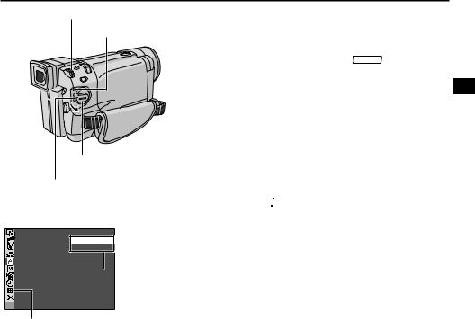
REC MODE – SP LP
 Sub Menu
GR-DVL1020/DVL820/DVL520 only
Recording Mode Setting
Set the tape recording mode depending on your preference.
1 Set the Power Switch to “ |
MANUAL |
” while pressing |
|
|
down the Lock Button located on the switch. The power lamp lights and the camcorder is turned on.
2 Press the MENU/BRIGHT wheel in. The Menu Screen appears.
3 Rotate the MENU/BRIGHT wheel to select
“ CAMERA” and press it. The CAMERA Menu appears.
4 Rotate the MENU/BRIGHT wheel to select “REC MODE” and press it. The Sub Menu appears. Select “SP” or “LP” by rotating the MENU/BRIGHT wheel and press it. Rotate the MENU/BRIGHT wheel to select “ 


 RETURN”, and press it twice. The Menu Screen closes.
•Audio Dubbing (Z pg. 63) and Insert Editing (Z pg. 64) are possible on tapes recorded in the SP mode.
•“LP” (Long Play) is more economical, providing 1.5 times the recording time.
NOTES:
cIf the recording mode is switched during recording, the playback picture will be blurred at the switching point.
cIt is recommended that tapes recorded in the LP mode on this camcorder be played back on this camcorder.
cDuring playback of a tape recorded on another camcorder, blocks of noise may appear or there may be momentary pauses in the sound.
14 EN GETTING STARTED (cont.)
MENU/BRIGHT Wheel
Power Switch
|
Lock Button |
|
Card Cover |
Label |
|
Clipped edge |
Power Lamp |
Memory card |
|
Display
|
|
QUAL I TY |
– |
F I NE |
|||
|
|
||||||
|
|||||||
|
|
|
I MAGE S I ZE |
– 1024X768 |
|||
|
|
|
REC SELECT |
– |
|
|
|
|
|
|
|
|
|
||
|
|
|
|
|
|
|
|
|
|
|
|
|
|
|
|

 RETURN
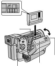
Loading A Memory Card
(GR-DVL1020/DVL820/DVL520 only)
The provided memory card is already inserted in the camcorder when you receive the camcorder.
1 Make sure the camcorder’s power is off.
2 Press PUSH OPEN and open the LCD monitor, then open the card cover (MEMORY CARD).
3 Insert the memory card clipped edge first.
•Do not touch the terminal on the reverse side of the label.
4 To close the card cover, push it until you hear a click.
To Unload A Memory Card . . .
..... in step 3 push the memory card, which then comes out of the camcorder automatically. Pull it out and close the card cover.
NOTES:
cBe sure to use only SD Memory Cards marked “
 ” or MultiMediaCards marked
“


 ”.
”.
cSome brands of memory cards are not compatible with this camcorder. Before purchasing a memory card , consult its manufacturer or dealer.
cBefore using a new memory card, it is necessary to FORMAT the card. Z pg. 36.
ATTENTION
Do not insert/remove the memory card while the camcorder is turned on, as this may cause the memory card to be corrupted or cause the camcorder to become unable to recognize whether or not the card is installed.
Picture Quality/Image Size Setting
(GR-DVL1020/DVL820/DVL520 only)
The Picture Quality/Image Size can be selected to best match your needs. Refer to the chart on page 27 for your selection.
1 Set the VIDEO/MEMORY Switch to “MEMORY”,
then set the Power Switch to “ |
MANUAL |
” while pressing |
|
|
down the Lock Button located on the switch. The power lamp lights and the camcorder turns on.
2 Press the MENU/BRIGHT wheel in. The Menu Screen appears.
3 Rotate the MENU/BRIGHT wheel to select
“  DSC” and press it. The DSC Menu appears.
4 Rotate the MENU/BRIGHT wheel to select “QUALITY” and press it. The Sub Menu appears. Rotate the MENU/BRIGHT wheel to select the desired mode and press it.
5 Rotate the MENU/BRIGHT wheel to select “IMAGE SIZE” and press it. The Sub Menu appears. Rotate the MENU/BRIGHT wheel to select the desired mode and press it.
6 Rotate the MENU/BRIGHT wheel to select
“ 


 RETURN”, and press it twice. The Menu Screen closes.

TAPE RECORDING & PLAYBACK |
EN 15 |
|
||
|
|
|
|
|
|
TAPE RECORDING |
|
|
|
|
& |
|
|
|
|
PLAYBACK |
|
|
|
|
CONTENTS |
|
|
|
|
|
|
||
|
TAPE RECORDING |
16 – 20 |
|
|
|
|
|
||
|
Basic Recording ..................................... |
16 |
|
|
|
Journalistic Shooting ............................... |
17 |
|
|
|
Self-Recording ...................................... |
17 |
|
|
|
Operation Mode .................................... |
17 |
|
|
|
Zooming ............................................ |
18 |
|
|
|
Video Light ......................................... |
19 |
|
|
|
Time Code ........................................... |
20 |
|
|
|
TAPE PLAYBACK ........................... |
21 – 24 |
|
|
|
Normal Playback ................................... |
21 |
|
|
|
Still Playback ....................................... |
21 |
|
|
|
Shuttle Search ...................................... |
21 |
|
|
|
Frame-By-Frame Playback ........................ |
21 |
|
|
|
Connections .................................. |
22 – 23 |
|
|
|
Blank Search ........................................ |
24 |
|
|
|
|
|
|
|
16 EN |
TAPE RECORDING |
Power lamp
Power Switch |
During
shooting
Lock Button
Recording Start/Stop Button
Display
25min Tape remaining time indicator (Approximate)
min  90 min
  89 min
  3 min
3 min
(Now calculating)
0 min 1 min
1 min 2 min
2 min
(Blinking) (Blinking) (Blinking)
BR I GHT
MENU/BRIGHT Wheel
180° 90°
PUSH OPEN Button |
VIDEO/MEMORY Switch |
|
(GR-DVL1020/DVL820/ |
|
DVL520 only) |
Tally lamp (lights while recording is in progress)
Basic Recording
NOTE:
You should already have performed the procedures listed below. If not, do so before continuing.
cPower (Z pg. 8)
cGrip Adjustment (Z pg. 10)
cViewfinder Adjustment (Z pg. 10)
cLoad A Cassette (Z pg. 12)
cRecording Mode Setting (Z pg. 13)
1 Remove the lens cap.
GR-DVL1020/DVL820/DVL520 only: Press PUSH OPEN, open the LCD monitor and set the VIDEO/ MEMORY Switch to “VIDEO”.
2 Set the Power Switch to “ |
AUTO |
” or “ |
MANUAL |
” |
while pressing down the Lock Button located on the switch.
Shooting while using the LCD monitor: Make sure the LCD monitor is fully open. Tilt it upward/ downward for best viewability.
Shooting while using the viewfinder: Close the LCD monitor.
•The power lamp lights and the camcorder enters the Record-Standby mode. “PAUSE” is displayed.
3 Press the Recording Start/Stop Button. “

 ” appears while recording is in progress.
To Stop Recording . . .
..... press the Recording Start/Stop Button. The camcorder re-enters the Record-Standby mode.
To Adjust The Brightness Of The Display . . .
..... rotate the MENU/BRIGHT wheel until the bright level indicator on the display moves and the appropriate brightness is reached.
•If you are using GR-DVL1020, it is also possible to adjust the brightness of the viewfinder by closing the LCD monitor and adjusting as described above.
NOTES:
cIf the Record-Standby mode continues for 5 minutes, the camcorder’s power shuts off automatically. To turn the camcorder on again, set the Power Switch to
“OFF”, then back to “ AUTO ” or “ MANUAL ”.
cThe image will not appear simultaneously on the LCD monitor and the viewfinder. It will appear in the viewfinder when the LCD monitor is in the lock position, and it will appear on the LCD monitor when fully extended.
cWhen a blank portion is left between recorded scenes on the tape, the time code is interrupted and errors may
occur when editing the tape. To avoid this, refer to “Recording from the middle of a tape” (Z pg. 20).
cTo turn the tally lamp or beep sounds off, Z pg. 46,
48.
For other notes, Z pg. 68

Self-
Recording
EN 17
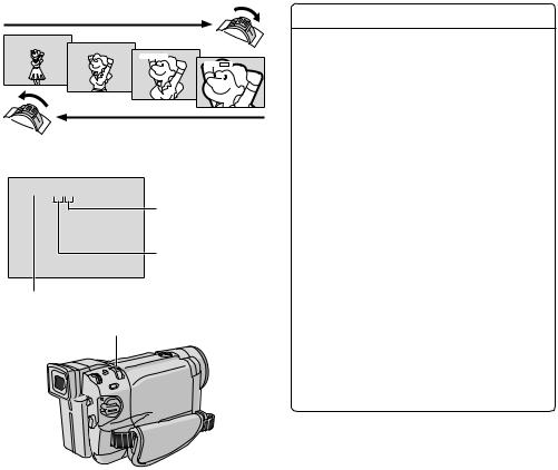
JOURNALISTIC SHOOTING
In some situations, different shooting angles may provide more dramatic results. Hold the camcorder in the desired position and tilt the LCD monitor in the most convenient direction. It can rotate 270° (90° downward, 180° upward).
SELF-RECORDING
You can shoot yourself while viewing your own image in the LCD monitor. Open the LCD monitor and tilt it upward 180° so that it faces forward, then point the lens toward yourself and start recording.
To turn on the camcorder, set the Power Switch to any operation mode except “OFF”while pressing down the Lock Button located on the switch.
|
Power Switch |
Power lamp |
MANUAL |
|
AUTO |
Lock Button
 OFF
OFF
PLAY
VIDEO/MEMORY Switch (GR-DVL1020/DVL820/DVL520 only; open the LCD monitor to access this switch.)
When the Power Switch is set to “ |
AUTO |
”, “ ” appears. |
||
|
||||
When set to “ |
MANUAL |
” or “PLAY”, there is no indication. |
||
|
|
|
|
|
(GR-DVL1020/DVL820/DVL520 only)
1024
When the Power Switch is set to “ AUTO ” or “ MANUAL ” and the VIDEO/MEMORY Switch is set to “MEMORY”, the currently selected image size appears. When set to “VIDEO”, there is no indication.
Operation Mode
Choose the appropriate operation mode according to your preference using the Power Switch and VIDEO/ MEMORY Switch (GR-DVL1020/DVL820/DVL520 only).
Power Switch Position
MANUAL |
: |
|
Allows you to set various recording functions using the Menus. If you want more creative capabilities than Full Auto recording, try this mode.
AUTO |
(Full Auto): |
|
Allows you to record using NO special effects or manual adjustments. Suitable for standard recording.
OFF:
Allows you to switch off the camcorder.
PLAY:
•Allows you to play back a recording on the tape.
•Allows you to transfer a still image recorded on the tape to a computer (GR-DVL320 only).
•Allows you to access data stored on the memory card or to transfer a still image stored on the memory card to a computer (GR-DVL1020/DVL820/ DVL520 only).
VIDEO/MEMORY Switch Position (GR-DVL1020/DVL820/DVL520 only)
VIDEO:
• Allows you to record on a tape or play back a tape. If “REC SELECT” is set to “  /
/  ” in the DSC Menu Screen, still images are recorded on the memory card as well.
•Zoom magnification over 10X is available (Z pg. 18, 47).
MEMORY:
Allows you to record on a memory card or access data stored on a memory card.
18 EN |
TAPE RECORDING (cont.) |
Zoom in (T: Telephoto)
1x W T
T
10x W T
T
20x W T
T
40x W  T
T
Zoom out (W: Wide angle)
Zoom display
10x W T
T
Digital zoom zone
10X (optical) zoom zone
Approximate zoom ratio
Power Zoom Lever
FEATURE: Zooming
PURPOSE:
To produce the zoom in/out effect, or an instantaneous change in image magnification.
OPERATION:
Zoom In
Slide the Power Zoom Lever towards “T”.
Zoom Out
Slide the Power Zoom Lever towards “W”.
nThe further you slide the Power Zoom Lever, the quicker the zoom action.
NOTES:
cFocusing may become unstable during Zooming. In this case, set the zoom while in Record-Standby,
lock the focus by using the manual focus
(Z pg. 43), then zoom in or out in Record mode.
cZooming is possible to a maximum of 700X, or it
can be switched to 10X magnification using the optical zoom (Z pg. 47).
cZoom magnification of over 10X is done through Digital image processing, and is therefore called Digital Zoom.
cDuring Digital zoom, the quality of image may suffer.
cDigital zoom cannot be used when the VIDEO/ MEMORY Switch is set to “MEMORY” (Z pg. 17).
cMacro shooting (as close as approx. 5 cm to the subject) is possible when the Power Zoom Lever is set all the way to “W”. Also see “TELE MACRO” in the Menu Screen on page 48.
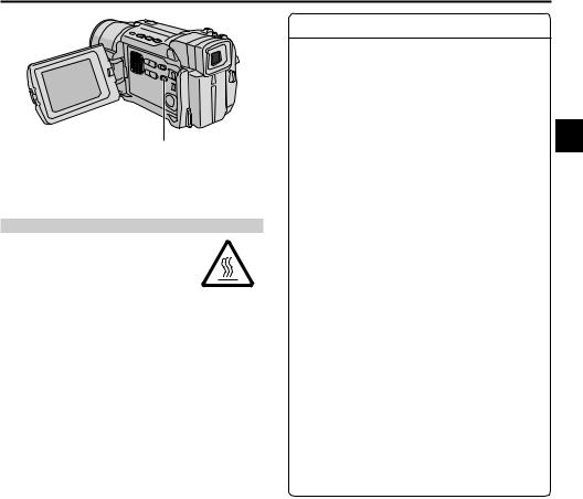
EN 19
LIGHT OFF/AUTO/ON Switch (Open the LCD monitor to access this switch.)
DANGER
nThe video light can become extremely hot. Do not touch it either while in operation or soon after turning it off, otherwise serious injury may result.
nDo not place the camcorder into the carrying case immediately after using the video light, since it remains extremely hot for some time.
nWhen operating, keep a distance of about 30 cm between the video light and people or objects.
nDo not use near flammable or explosive materials.
nDo not place the camcorder in a cabinet or box while the video light is in operation.
nWhen using the video light, if you wish to install the camcorder in a fixed position, attach it to a tripod, etc. Do not affix it directly to a surface such as a table top.
nIt is recommended that you consult your nearest JVC dealer for replacing the video light.
FEATURE: Video Light
PURPOSE:
To brighten the scene when natural lighting is too dim.
OPERATION:
Set LIGHT OFF/AUTO/ON as required:
OFF : Turns off the light.
AUTO : Automatically turns on the light when the camcorder senses insufficient lighting on the subject.
ON : Always keeps the light on as long as the camcorder is turned on.
nThe video light can only be used with the camcorder’s power on.
nIt is recommended to set the white balance (Z pg. 45) to  when you use the video light.
nWhen not using the video light, turn it off to save battery power.
NOTES:
cEven if the battery indicator (  ) does not blink due to low battery charge, the camcorder may turn off automatically when you turn on the video light, or when you start recording with the video light turned on.
cWhen LIGHT OFF/AUTO/ON is set to “AUTO”:
•Depending on the lighting conditions, the video light may keep turning on and off. In this case, manually switch the light on or off using LIGHT OFF/AUTO/ON.
•While the “SHUTTER” or “SPORTS” mode
(Z pg. 39) is engaged, the light is likely to stay on.
•While the “TWILIGHT” mode (Z pg. 39) is engaged, the light will not activate.
•While the “Night-Scope” mode (Z pg. 38) is engaged, the light will not activate.
20 EN |
TAPE RECORDING (cont.) |
Time Code
During recording, a time code is recorded on the tape. This code is to confirm the location of the recorded scene on the tape during playback.
If recording starts from a blank portion, the time code begins counting from “00:00:00” (minute:second:frame). If recording starts from the end of a previously recorded scene, the time code continues from the last time code number.
To perform Random Assemble Editing (Z pg. 58 – 62), time code is necessary. If during recording a blank portion is left partway through the tape, the time code is interrupted. When recording is resumed, the time code starts counting up again from “00:00:00”. This means the camcorder may record the same time codes as those existing in a previously recorded scene. To prevent this, perform “Recording From The Middle of A Tape” below in the following cases;
•When shooting again after playing back a recorded tape.
•When power shuts off during shooting.
•When a tape is removed and re-inserted during shooting.
•When shooting using a partially recorded tape.
•When shooting on a blank portion located partway through the tape.
•When shooting again after shooting a scene then opening/closing the cassette holder cover.
Display
|
|
|
|
Frames are not displayed |
||
|
|
|
|
during recording. |
||
|
|
|
|
|
|
Minutes |
|
|
|
|
|
|
Seconds |
|
|
|
|
|
|
Frames |
|
|
|
|
|
|
(25 frames = 1 second) |
12 : 34 : 24 |
|
|
||||
|
|
|
||||
Recording From The Middle Of A Tape
1.Play back a tape or use Blank Search (Z pg. 24) to find the spot at which you want to start recording, then engage the Still Playback mode (Z pg. 21).
2.Set the Power Switch to “ AUTO ” or “ MANUAL ” while pressing down the Lock Button located on the switch, then start recording.
NOTES:
cThe time code cannot be reset.
cDuring fast-forwarding and rewinding, the time code indication does not move smoothly.
cThe time code is displayed only when “TIME CODE” is set to “ON” (Z pg. 49, 50).
When a blank portion is recorded on a tape
Time code |
|
Time code |
Time code |
|
||||
00:00:00 |
|
|
05:43:21 |
00:00:00 |
|
|||
|
|
|
|
|
|
|
|
|
Tape |
|
Already recorded scene |
|
Blank |
|
|
Newly recorded scene |
|
|
|
|
|
|
|
|||
Shooting start point |
Shooting stop point |
Shooting start point |
||||||
Proper recording |
|
|
|
|
|
|
||
Time code |
|
Time code |
Time code |
|
||||
00:00:00 |
|
|
05:43:21 |
05:44:00 |
|
|||
|
|
|
|
|
||||
Tape |
|
Already recorded scene |
|
New scene |
|
Latest scene |
||
|
|
|
|
|
|
|
|
|
Shooting start point |
Shooting start point |
Shooting start point |

TAPE PLAYBACK |
EN 21 |
 Stop Button (5)
 Rewind Button (2)
 Play/Pause Button (4/6)
 Fast-Forward Button (3)


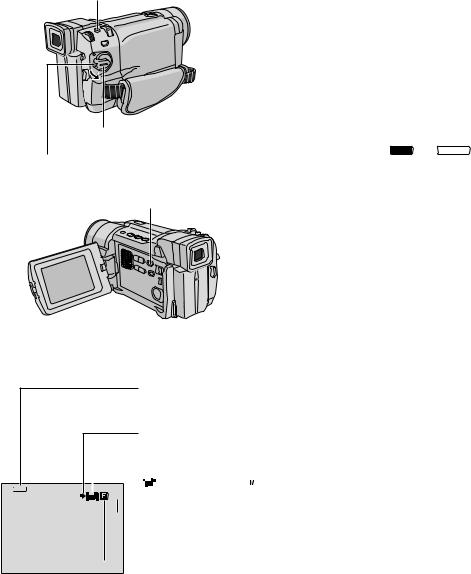
 Power Zoom Lever (VOL.)

 VIDEO/MEMORY Switch
 (GR-DVL1020/DVL820/ DVL520 only; open the LCD monitor to access this switch.)
Speaker
NOTES:
Normal Playback
1
2 Set the VIDEO/MEMORY Switch to “VIDEO” (GR-DVL1020/DVL820/DVL520 only), then set the Power Switch to “PLAY” while pressing down the Lock Button located on the switch. To start playback, press 4/
6.
•To stop playback, press 5.
•Press 2to rewind, or 3to fast-forward the tape during Stop mode.
To Control The Speaker Volume . . .
..... slide the Power Zoom Lever (VOL.) towards “+” to turn up the volume, or towards “–” to turn down the volume.
cIf Stop mode continues for 5 minutes when power is supplied from a battery, the camcorder shuts off automatically. To turn on again, set the Power Switch to “OFF”, then to “PLAY”.
cThe playback picture can be viewed in the LCD monitor, viewfinder or on a connected TV (Z pg. 22).
cYou can also view the playback picture on the LCD monitor with it flipped over and pushed against the camera body.
cLCD monitor/viewfinder indications:
•When power is supplied from a battery: the “ ” battery pack remaining power indicator is displayed. When power is supplied from an AC outlet: “
 ” does not appear.
•During Stop mode, none of the indications are displayed.
cWhen a cable is connected to the AV connector, the sound is not heard from the speaker.
Still Playback: Pauses during playback.
1)Press 4/6during playback.
2)To resume normal playback, press 4/6again.
cIf still playback continues for more than about 3 minutes, the camcorder’s Stop mode is automatically engaged. After 5 minutes in the Stop mode, the camcorder’s power is automatically turned off.
cWhen 4/6is pressed, the image may not pause immediately while the camcorder stabiliseds the still image.
Shuttle Search: Allows high-speed search in either direction.
1)Press 3for forward or 2for reverse search during playback.
2)To resume normal playback, press 4/6.
cDuring playback, press and hold 2or 3. The search continues as long as you hold the button. Once you release it, normal playback resumes.
cA slight mosaic effect appears on screen during Shuttle Search. This is not a malfunction.
Frame-By-Frame Playback: Allows frame-by-frame search.
1)Engage Still Playback.
2)Rotate the MENU/BRIGHT wheel towards “+” for forward Frame-By-Frame Playback, or towards “–” for reverse
Frame-By-Frame Playback during Still Playback.
cTo resume normal playback, press 4/6.
cYou can also use the provided remote control for Frame-By-Frame Playback (Z pg. 56).
Slow-Motion Playback/Playback Special Effects and Playback Zoom
Available only with the remote control (provided) (Z pg. 56, 57).
ATTENTION
During Shuttle Search, parts of the picture may not be clearly visible, particularly on the left side of the screen.
22 EN |
TAPE PLAYBACK (cont.) |
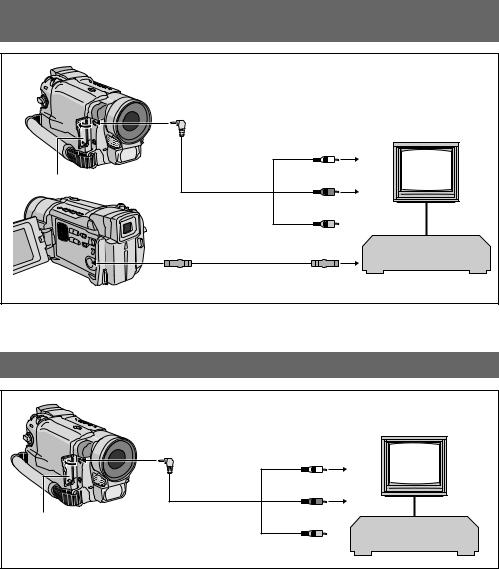
Connections
These are some basic types of connections. When making the connections, refer also to your VCR and TV instruction manuals.
A.Connection to a TV or VCR equipped with an S-VIDEO IN and A/V input connectors
|
To AV |
|
|
|
|
To TV or VCR |
|
|
Audio/Video cable |
White to |
TV |
Connector cover* |
(provided) |
AUDIO L IN** |
|
|
|
Red to |
|
|
|
AUDIO R IN** |
|
|
|
Yellow: |
|
|
To S-VIDEO |
Not connected |
|
|
|
VCR |
|
|
|
|
|
|
S-Video cable |
To S-VIDEO IN |
|
|
(optional) |
|
|
|
|
|
*When connecting the cables, open this cover.
**The Audio cable is not required for watching still images only.
B.Connection to a TV or VCR equipped only with A/V input connectors
|
|
To TV or VCR |
|
|
To AV |
|
|
|
|
TV |
|
|
|
White to |
|
|
|
AUDIO L IN** |
|
Connector cover* |
Audio/Video cable |
Red to |
|
(provided) |
AUDIO R IN** |
||
|
|||
|
|
VCR |
|
|
|
Yellow to |
|
|
|
VIDEO IN |
*When connecting the cables, open this cover.
**The Audio cable is not required for watching still images only.

1
2 Connect the camcorder to a TV or VCR as shown in the illustration (Z pg. 22).
If using a VCR . . . go to step 3. If not . . . go to step 4.
3 Connect the VCR output to the TV input, referring to your VCR’s instruction manual.
4 Turn on the camcorder, the VCR and the TV.
5 Set the VCR to its AUX input mode, and set the TV to its VIDEO mode.
To choose whether or not the following displays appear on the connected TV . . .
• Date/Time
..... set “DATE/TIME” to “AUTO”, “ON” or “OFF” in the Menu Screen (Z pg. 50).
Or, press DISPLAY on the remote control (provided) to turn on/off the date indication.
• Time Code
..... set “TIME CODE” to “ON” or “OFF” in the Menu Screen (Z pg. 50).
• Playback Sound Mode, Tape Speed And Tape Running Displays for tape playback
..... set “ON SCREEN” to “LCD” or “LCD/TV” in the Menu Screen (Z pg. 50).
EN 23
NOTES:
cIt is recommended to use the AC Adapter as the power supply instead of the battery pack (Z pg. 9).
cTo monitor the picture and sound from the camcorder without inserting a tape or memory card*, set the camcorder’s Power Switch to “ AUTO ” or “ MANUAL ”, then set your TV to the appropriate input mode.
*GR-DVL1020/DVL820/DVL520 only
cMake sure you adjust the TV sound volume to its minimum level to avoid a sudden burst of sound when the camcorder is turned on.
cIf you have a TV or speakers that are not specially shielded, do not place the speakers adjacent to the TV as interference will occur in the camcorder playback picture.
cWhile the Audio/Video cable is connected to the AV connector, sound cannot be heard from the speaker.
cIf no image is displayed or no sound is heard from the
TV, set “S/AV INPUT” to “OFF” in the Menu Screen (GR-DVL1020/DVL820 only, Z pg. 50).
24 EN |
TAPE PLAYBACK (cont.) |
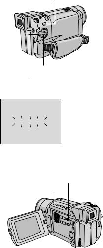
BLANK Button
Power Switch |
Lock Button
Display
44
BLANK SEARCH
VIDEO/MEMORY Switch (GR-DVL1020/ DVL820/DVL520 only; open the LCD monitor to access this switch.)
Stop Button (5)
Blank Search
Helps you find where you should start recording in the middle of a tape to avoid time code interruption (Z pg. 20).
1
2 Set the VIDEO/MEMORY Switch to “VIDEO” (GR-DVL1020/DVL820/DVL520 only), then set the Power Switch to “PLAY” while pressing down the Lock Button located on the switch.
3 Press BLANK.
•“BLANK SEARCH” appears blinking and the camcorder automatically starts reverse or forward shuttle search, then stops at the spot which is about 3 seconds of tape before the beginning of the detected blank portion.
To cancel Blank Search midway . . .
..... press 5.
NOTES:
cIn step 3, if the current position is at a blank portion the camcorder searches in the reverse direction, and if the current position is at a recorded portion the camcorder searches in the forward direction.
cBlank Search does not work if “HEAD CLEANING REQUIRED. USE CLEANING CASSETTE” has appeared with the tape.
cIf the beginning or end of the tape is reached during Blank Search, the camcorder stops automatically.
cA blank portion which is shorter than 5 seconds of tape may not be detected.
cThe detected blank portion may be located between recorded scenes. Before you start recording, make sure there is no recorded scene after the blank portion.

MEMORY CARD RECORDING & PLAYBACK |
EN 25 |
MEMORY CARD RECORDING
&
PLAYBACK
Memory Card recording features are available on GR-DVL1020,GR-DVL820 and GR-DVL520.
CONTENTS |
|
|
MEMORY CARD |
RECORDING ......... |
26 – 27 |
Basic Shooting (Snapshot) ............... |
26 – 27 |
|
MEMORY CARD |
PLAYBACK ........... |
28 – 29 |
Normal Playback .................................. |
28 |
|
Auto Playback ..................................... |
|
28 |
Index Playback .................................... |
|
29 |
Viewing File Information ......................... |
29 |
|
Removing On-Screen Display .................... |
29 |
|
ADVANCED FEATURES .................... |
30 – 36 |
|
Protecting Files .................................... |
|
30 |
Deleting Files ...................................... |
|
31 |
Dubbing Still Images Recorded On A Tape To A |
||
Memory Card ....................................... |
|
32 |
E-Mail Clip Recording ............................. |
33 |
|
Setting Print Information |
|
|
(DPOF Setting) ............................. |
|
34 – 35 |
Making A New Folder ............................ |
36 |
|
Initialising A Memory Card ...................... |
36 |
|
26 EN |
MEMORY CARD RECORDING |
SNAPSHOT Button
Basic Shooting (Snapshot)
Power Switch
Lock Button
VIDEO/MEMORY Switch (Open the
LCD monitor to access this switch.)
You can use your camcorder as a digital still camera for taking snapshots.
NOTE:
You should already have performed the procedures listed below. If not, do so before continuing.
cPower (Z pg. 8)
cGrip Adjustment (Z pg. 10)
cViewfinder Adjustment (Z pg. 10)
cLoading A Memory Card (Z pg. 14)
cPicture Quality/Image Size Setting (Z pg. 14)
1 Set the VIDEO/MEMORY Switch to “MEMORY”, then set the Power Switch to “ AUTO ” or “ MANUAL ” while pressing down the Lock Button located on the switch.
2 Press SNAPSHOT. “PHOTO” appears while the snapshot is being taken.
The image is recorded on the memory card.
•Still images are recorded in the snapshot mode with no frame.
Image Size
Displays the image file size: 1280 (1280 x 960)*, 1024 (1024 x 768) or 640 (640 x 480) (Z pg. 14).
* GR-DVL1020/DVL820 only.
Shooting icon
Appears and blinks during shooting.
|
|
|
|
|
|
Card icon |
|
|
|||
|
|
|
|
|
|
Appears during shooting and blinks when a memory card is not loaded: |
|||||
1024 |
|
|
|
|
15 |
|
|
|
(SD Memory Card) or |
|
(MultiMediaCard). |
|
|
|
|
|
|
|
|
|
|
||
|
|
|
|
|
|
|
|
|
|
|
|
 Remaining number of shots
Displays the remaining number of shots that can be stored.
The number increases or decreases depending on the Picture Quality/Image Size, etc.
 Picture Quality
Displays the quality of image: F (Fine) or S (Standard) (in order of quality) (Z pg. 14).
Display
 Loading...